EP2058210B1 - Dispositif de direction électrique - Google Patents
Dispositif de direction électrique Download PDFInfo
- Publication number
- EP2058210B1 EP2058210B1 EP08168251A EP08168251A EP2058210B1 EP 2058210 B1 EP2058210 B1 EP 2058210B1 EP 08168251 A EP08168251 A EP 08168251A EP 08168251 A EP08168251 A EP 08168251A EP 2058210 B1 EP2058210 B1 EP 2058210B1
- Authority
- EP
- European Patent Office
- Prior art keywords
- rack
- torque
- rotation
- steering
- projection
- Prior art date
- Legal status (The legal status is an assumption and is not a legal conclusion. Google has not performed a legal analysis and makes no representation as to the accuracy of the status listed.)
- Expired - Fee Related
Links
Images


Classifications
-
- B—PERFORMING OPERATIONS; TRANSPORTING
- B62—LAND VEHICLES FOR TRAVELLING OTHERWISE THAN ON RAILS
- B62D—MOTOR VEHICLES; TRAILERS
- B62D1/00—Steering controls, i.e. means for initiating a change of direction of the vehicle
- B62D1/02—Steering controls, i.e. means for initiating a change of direction of the vehicle vehicle-mounted
- B62D1/16—Steering columns
-
- B—PERFORMING OPERATIONS; TRANSPORTING
- B62—LAND VEHICLES FOR TRAVELLING OTHERWISE THAN ON RAILS
- B62D—MOTOR VEHICLES; TRAILERS
- B62D5/00—Power-assisted or power-driven steering
- B62D5/04—Power-assisted or power-driven steering electrical, e.g. using an electric servo-motor connected to, or forming part of, the steering gear
- B62D5/0457—Power-assisted or power-driven steering electrical, e.g. using an electric servo-motor connected to, or forming part of, the steering gear characterised by control features of the drive means as such
- B62D5/046—Controlling the motor
- B62D5/0469—End-of-stroke control
Definitions
- the present invention relates to an electric power steering device in which an auxiliary steering force is imparted from an electric motor to a steering unit of a vehicle such as an automobile.
- An electric power steering device is a device in which an electric motor generates an auxiliary torque in accordance with a magnitude of a steering torque, and the auxiliary torque is transmitted to a steering unit, to thereby reduce a steering effort required by a driver for steering.
- a rack shaft in order to prevent a steering turn of wheels from exceeding a certain range, a rack shaft has rack ends and a rack housing portion for containing the rack shaft has housing ends, with the rack end and housing end on the same side forming a rack end mechanism.
- rack end angle this angle of the wheels, as well as angle of the steering wheel or the like that imparts this angle of the wheels
- Japanese examined patent publication No. 6-4417 discloses a device in which, when a steering angle (amount of operation) of a steering wheel reaches a predetermined angle at a position near the rack end angle, a target current value is reduced as the turning angle of wheels increases, and when the turning angle of wheels reaches the rack end angle, the target current value is set to zero, to thereby prevent the rack end mechanism from suffering a large impact.
- Japanese unexamined patent publication No. 2006-248252 discloses a device in which, when the wheels are at a certain turning angle ⁇ 1 or more near the rack end angle, and when a rotational speed ⁇ M of the motor is a set value ⁇ 1 or more, a gain of a steering torque value T is reduced.
- a rack and pinion electric power steering device configured to transmit an auxiliary torque to a steering unit of front wheels
- the rack and pinion electric power steering device including: an operator, preferably a steering wheel; an electric motor configured to generate the auxiliary torque in accordance with at least a steering torque generated by input from the operator; the steering unit of front wheels which includes a pinion shaft; a rotation terminating mechanism which provides a motion terminating end of the operator, and regulates a first maximum steering angle input from the operator, the rotation terminating mechanism being disposed between the operator and a torque sensor which detects the steering torque; and a steering angle regulating mechanism which regulates a second maximum steering angle of the front wheels, the steering angle regulating mechanism being disposed between the torque sensor and the front wheels; wherein the rack and pinion electric power steering device (100) steers the front wheels by moving the rack shaft in an axis direction of the rack shaft according to the steering torque and the auxiliary torque, and wherein the first maximum steering angle regulated by the rotation terminating mechanism
- the rotation terminating mechanism blocks a further operation of the operator at the motion terminating end, and therefore, the torque sensor cannot detect a signal that otherwise generates further auxiliary torque by the electric motor in a blocked direction.
- the device has a function of reducing the torque detected by the torque sensor.
- the steering angle regulating mechanism is a member for regulating a movement of the rack shaft in the axis direction of the rack shaft, and that the first maximum steering angle regulated by the rotation terminating mechanism is set to be smaller than the second maximum steering angle regulated by the member.
- the steering angle regulating mechanism is a rack end mechanism which includes a housing end provided to a housing for storing the rack shaft and a rack end provided to the rack shaft, and that the first maximum steering angle regulated by the rotation terminating mechanism is set to be smaller than the second maximum steering angle regulated by the rack end mechanism.
- the rotation terminating mechanism includes a deceleration mechanism and is configured to alter an allowable range of turning operation of the operator limited by the motion terminating end.
- the rotation terminating mechanism can alter the allowable range of turning operation of the operator, by the deceleration mechanism. Therefore, the driver operating the steering wheel (operator) can be provided with the same range of steering angle (operation amount) including right and left as the range in the conventional device.
- the electric power steering device described above further includes a torque sensor configured to detect the steering torque, wherein the steering unit of the front wheels further includes an auxiliary torque transmission mechanism, and the rotation terminating mechanism is disposed between the torque sensor and the auxiliary torque transmission mechanism.
- the rotation terminating mechanism blocks a further turning operation of the operator at the motion terminating end, and in addition, blocks the rotation of the pinion shaft disposed on an auxiliary torque transmission mechanism (for example, deceleration mechanism, specifically, worm wheel gear) side relative to the torque sensor, which pinion shaft rotates together with the auxiliary torque transmission mechanism.
- auxiliary torque transmission mechanism for example, deceleration mechanism, specifically, worm wheel gear
- the rack-and-pinion gears including the pinion gear provided on the pinion shaft (worm wheel) and the rack gear engaging with the pinion gear do not suffer overload caused along with a rotation of the pinion shaft that transmits an auxiliary torque.
- the angle of steering turn of wheels at which the rotation of the pinion shaft is blocked can serve as the rack end angle, which limits the assist at a position near the rack end.
- the rotation terminating mechanism blocks the rotation of the pinion shaft, and thus the rotation by overshoot is not transmitted to the rack-and-pinion gears, preventing the rack-and-pinion gears from suffering the overload (suppressing the overload).
- the rotation terminating mechanism includes: an input shaft with an external gear, to which a rotation of a rotary shaft of the operator is transmitted; a ring gear having an internal gear configured to engage with the external gear of the input shaft, and having a first projection on an outer periphery of the ring gear; and a ring-shaped fixed portion surrounding the ring gear, wherein the external gear of the input shaft and the internal gear of the ring gear serves as the deceleration mechanism, and a second projection configured to limit a rotation of the first projection by being brought into contact with the first projection is provided on an inner periphery of the fixed portion.
- a rotation angle of the ring gear can be reduced relative to a rotation angle of the input shaft, and thus the driver operating the steering wheel (operator) can be provided with the same range of steering angle (operation amount) including right and left as the range in the conventional device.
- the operation amount of the steering wheel corresponding to the rack end angle can be altered, which allows an introduction of the steering device to various types of vehicles.
- the rotation terminating mechanism includes: a planetary gear reducer unit as the deceleration mechanism including an outer ring gear, planetary gears, a planetary carrier and a sun gear, and a fixed portion for fixing the outer ring gear, wherein a first projection is provided on the planetary carrier, a rotation of a rotary shaft of the operator is transmitted to the sun gear, and a second projection configured to limit a rotation of the first projection by being brought into contact with the first projection is provided on at least one of the fixed portion and the outer ring gear.
- a planetary gear reducer unit as the deceleration mechanism including an outer ring gear, planetary gears, a planetary carrier and a sun gear, and a fixed portion for fixing the outer ring gear, wherein a first projection is provided on the planetary carrier, a rotation of a rotary shaft of the operator is transmitted to the sun gear, and a second projection configured to limit a rotation of the first projection by being brought into contact with the first projection is provided on at least one of the fixed portion and the
- the rotation terminating mechanism with the use of the planetary gear reducer unit, the rotation angle of the planetary carrier relative to the rotation angle of the sun gear can be reduced, and thus the driver operating the steering wheel (operator) can be provided with the same range of steering angle (operation amount) including right and left as the range in the conventional device.
- the rotation terminating mechanism can be mounted in a balanced manner, i.e., coaxially with the rotary shaft of the operator. At the same time, when the first projection and the second projection are brought into contact with each other, a load per planetary gear is shared by the planetary carrier, and thus the device can tolerate a larger load. Accordingly, the rotation terminating mechanism can be made smaller by that amount.
- the rotation terminating mechanism includes: a thread portion with an external thread, to which a rotation of a rotary shaft of the operator is transmitted; a first stopper in a ring shape which has a first projection on an outer periphery of the first stopper and is fixed to the thread portion; a second stopper which has an internal thread configured to engage with the thread portion, is disposed above the first stopper, and has a second projection configured to be brought into contact with the first projection and formed in a lower face of the second stopper; a third stopper which has an internal thread configured to engage with the thread portion, is disposed below the first stopper, and has a third projection configured to be brought into contact with the first projection and formed in an upper face of the third stopper; and a guide member configured to limit rotations of the second and third stoppers and move the second and third stoppers along an axial direction of the thread portion, wherein the thread portion, the second stopper, the third stopper and the guide member serve as the
- the rotation of the thread portion is converted into the vertical shift of the second and third stoppers, and the rotation angle of the thread portion until the first projection of the first stopper is brought into contact with the second projection of the second stopper or the third projection of the third stopper becomes large. Therefore, the driver operating the steering wheel (operator) can be provided with the same range of steering angle (operation amount) including right and left as the range in the conventional device.
- the steering angle including right and left of the steering wheel can be set to a value as large as, for example, 2 turns or more (i.e., 720° or more), and thus can be applied to vehicles other than automobile.
- the outer diameter of the rotation terminating mechanism can be made small, further improving mountability on the vehicle.
- the torque sensor is a magnetostrictive torque sensor.
- the steering angle regulating mechanism is a rack end mechanism which includes a housing end provided to a rack housing portion for storing the rack shaft and a rack end provided to the rack shaft, and wherein the rack end and the housing end are configured to have a room therebetween so as not to come into contact with each other at a motion terminating end of the operator provided by the rotation terminating mechanism.
- FIGs. 1 to 9A - 9C A first embodiment of the present invention will be described with reference to FIGs. 1 to 9A - 9C .
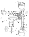
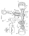
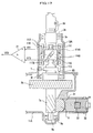
- FIG. 1 is a configuration diagram of an electric power steering device according to the first embodiment of the present invention.
- FIG. 2 is a side view showing portions around a torque sensor and a pinion gear in a steering gear box of FIG. 1 .
- An electric power steering device 100A includes, as shown in FIG. 1 , a steering wheel (operator) 3, a steering wheel shaft 3a attached thereto, a shaft 3c and an input shaft 3d, all of which shafts are connected through two universal joints 3b.
- the input shaft 3d is connected to a pinion shaft 7 through a torsion bar 111.
- the left front wheel 1L and the right front wheel 1R are connected through respective tie rods 9, 9.
- the rack shaft 8 is supported slidably in lateral directions in such a manner that the rack shaft 8 is pushed from an opposite side of the rack gear 8a toward a pinion gear 7a side by a rack guide 31.
- the rack gear 8a is pressed to the pinion gear 7a by an adjusting bolt 32 through a compression spring 33.
- a lock nut 34 is for preventing the adjusting bolt 32 from loosening.
- the pinion shaft 7 connected to the input shaft 3d through the torsion bar 111 is supported by a steering gear box 10A: an upper portion, a middle portion and a lower portion of the pinion shaft 7 are supported through bearings 3e, 3f and 3g, respectively.
- a rack housing portion 11A is configured to hold the pinion gear 7a, the rack shaft 8 and the bearing 3g, as well as a sliding bearing 14 therein which allows a slidable movement of the rack shaft 8 in an axial direction of the rack shaft 8.
- housing ends 11a, 11a are provided on lateral ends of the rack housing portion 11A.
- the rack ends 8b, 8b and the housing ends 11a, 11a are provided not for the same purpose, but only for centering the movement of the rack shaft 8 during a unit assembly of the steering gear box 10A upon a vehicle production or the like.
- the maximum turning angle of the wheels (rack end angle) is limited in terms of an operation amount (steering angle) of the steering wheel 3 fully to the right and the left, which is set by a rotation terminating mechanism 6A (which will be described later), while the rack end 8b and the rack housing 11a for positioning during the assembly have a room therebetween so as not to come into contact with each other at the maximum turning angle of the wheels.
- rack end angle means the maximum setting turning angle of the wheels defined by the rotation terminating mechanism.
- the electric power steering device 100A can change traveling direction of the vehicle during the operation of the steering wheel 3.
- the rack shaft 8, the rack gear 8a and the tie rods 9, 9 form a steering wheel turn mechanism.
- the electric power steering device 100A also has an electric motor 4 for supplying an auxiliary steering effort (auxiliary torque) to reduce a steering effort (steering torque) required at the steering wheel 3.
- the electric motor 4 has an output shaft with a worm gear 5a which engages with a worm wheel gear 5b provided on the pinion shaft 7.
- the worm gear 5a and the worm wheel gear 5b form a deceleration mechanism (auxiliary torque transmission mechanism) 5A.
- a rotor of the electric motor 4 and the components connected to the electric motor 4, such as the worm gear 5a, the worm wheel gear 5b, the pinion shaft 7, the rack shaft 8, the rack gear 8a and the tie rods 9, 9, form a steering unit.
- ⁇ M represents a rotational angular velocity (hereinbelow, also simply referred to as “angular velocity”) of the electric motor 4
- T M represents a torque generated at the electric motor 4.
- a steering torque applied to the steering wheel 3 is represented as Ts
- an assist amount by the torque (auxiliary torque) generated at the electric motor 4, which has been powered through the deceleration mechanism is represented as A H
- the steering torque Ts can be represented by the following formula (2).
- Ts Tp / 1 + k A VS
- the electric power steering device 100A also includes an electric motor drive circuit 23 configured to drive the electric motor 4; a resolver 25; a torque sensor 110 configured to detect (measure) a pinion torque Tp applied to the pinion shaft 7; a differential amplifier 21 configured to amplify the output from the torque sensor 110; the vehicle speed sensor Sv configured to detect (measure) a vehicle speed; the rotation terminating mechanism 6A configured to regulate a motion of the steering wheel 3 input to the torque sensor 110, in terms of the rack end ; and a steering control ECU (Electric Control Unit) 200 configured to control the driving of the electric motor 4.
- an electric motor drive circuit 23 configured to drive the electric motor 4
- a resolver 25
- a torque sensor 110 configured to detect (measure) a pinion torque Tp applied to the pinion shaft 7
- a differential amplifier 21 configured to amplify the output from the torque sensor 110
- the vehicle speed sensor Sv configured to detect (measure) a vehicle speed
- the rotation terminating mechanism 6A configured to regulate a motion of the steering wheel
- the electric motor drive circuit 23 has switching elements, such as three-phase FET bridge circuit, and is configured to generate a square-wave voltage based on duty signals (DUTY U, DUTY V, DUTY W) from the steering control ECU 200 (see FIG. 7 ), to thereby drive the electric motor 4.
- switching elements such as three-phase FET bridge circuit
- the electric motor drive circuit 23 also has a function to detect (measure) a three-phase electric motor current I (IU, IV, IW) using a Hall element (not shown).
- the resolver 25 is configured to detect (measure) a rotation angle ⁇ m of the electric motor 4 and to output an angular signal ⁇ , and examples include a sensor for detecting a change in magnetoresistance which is positioned in the vicinity of a magnetic rotor having a plurality of recess portions and projection portions arranged evenly along a circumference of the rotor.
- the vehicle speed sensor Sv is configured to detect (measure) the vehicle speed as a pulse number per unit time, and to output a vehicle speed signal VS.
- FIG. 3 is a cross section taken along a line A-A in FIG. 2 .
- FIG. 4 illustrates displacements of an upper loose part, a lower loose part and a slider when a steering torque is applied, in which (a) shows a neutral state, (b) shows a state in which a left steering torque is applied and the pinion shaft 7 is rotated by approximately 30° from the neutral state, in a left-handed (anticlockwise) direction about the input shaft 3d, and (c) shows a state in which a right steering torque is applied and the pinion shaft 7 is rotated by approximately 30° from the neutral state, in a right-hand (clockwise) direction about the input shaft 3d.
- the torque sensor 110 is configured to detect (measure) a magnitude and a direction of a steering torque Ts applied to the steering wheel 3 (see FIG. 1 ), and as shown in FIG. 2 , it is assembled with the input shaft 3d and the pinion shaft 7, and contained together with the bearings 3e, 3f in a lid portion 13A, which is in a flanged connection with the upper portion of the rack housing portion 11A.
- the torque sensor 110 is supported by the bearings 3e, 3f and a bearing (not shown) coaxially provided between the input shaft 3d and the pinion shaft 7, in such a manner that the torque sensor 110 and the bearings are relatively rotatable to each other.
- the input shaft 3d and the pinion shaft 7 are connected through the torsion bar 111.
- the torque sensor 110 includes: an upper loose part 112 on a lower end side of the input shaft 3d; a lower loose part 113 on an upper end side of the pinion shaft 7; pins 117A, 117A and 117B, 117B (see FIG. 3 ) fixed to an outer periphery of the upper loose part 112 and an outer periphery of the lower loose part 113, respectively; a slider 115; and a first detection coil 114A and a second detection coil 114B.
- the upper loose part 112 has opposing loose pieces 112a, 112a.
- the lower loose part 113 is a thick-walled cylinder including: a hollow portion 113a at a center; thin circumferential portions 113b, 113b which are opposing thin side walls formed in the cylinder; and protruding circumferential portions 113c, 113c which are opposing thicker portions as the rest of the cylinder.
- the upper loose part 112 and the lower loose part 113 are combined in such a manner that the loose piece 112a is overlaid on the thin circumferential portion 113b in a radial direction.
- a gap is formed between an outer periphery of the thin circumferential portion 113b and an inner periphery of the loose piece 112a, so that a rotation is allowed with a predetermined relative rotation angle, such as -5° to +5°.
- a relative rotation with a larger angle an end portion in a rotational direction of the loose piece 112a and an end portion in a rotational direction of the protruding circumferential portion 113c are brought into contact with each other, and the torsion bar 111 is not further distorted.
- a diameter (distance from the axial center) of the outer periphery of the loose piece 112a of the upper loose part 112 and a diameter (distance from the axial center) of the outer periphery of the protruding circumferential portions 113c of the lower loose part 113 are the same.
- the slider 115 in a shape of a cylinder is slidably fitted.
- opposing vertical slots 118A, 118A for inserting pins 117A, 117A are formed in an axial direction
- opposing oblique slots 118B, 118B for inserting pins 117B, 117B are formed.
- the torque sensor 110 is assembled by, first putting the torsion bar 111, the upper loose part 112 and the lower loose part 113 together, passing the pins 117A, 117A, 117B, 117B through the slots 118A, 118A and the oblique slots 118B, 118B, and press-fitting the pins into respective pin holes (not shown) formed in the upper loose part 112 and the lower loose part 113.
- the slider 115 is made of a magnetic core material.
- a first detection coil 114A and a second detection coil 114B surrounded by a yoke material are fixed to an inner periphery of the lid portion 13A, in such a manner that they face to an outer periphery of the slider 115 and are arranged two-tiered.
- the pins 117A, 117A, the pins 117B, 117B, the slots 118A, 118A, the oblique slots 118B, 118B form a cam mechanism, and when the upper loose part 112 and the lower loose part 113 are distorted, as shown in FIG. 4 , the slider 115 vertically moves in an axial direction, with the guidance along the slots 118A and the oblique slots 118B.
- Such a vertical displacement of the slider 115 made of magnetic core generates change in magnetic flux density around the first detection coil 114A and the second detection coil 114B, with which an inductance of one of the first detection coil 114A and the second detection coil 114B becomes large, while an inductance of the other becomes small.
- the first detection coil 114A and the second detection coil 114B output torque detection voltages VT1, VT2, respectively, as shown in FIG. 5 .
- the torque detection voltages VT1, VT2 from the detection coils 114A, 114B are amplified by the differential amplifier 21 (see FIG. 2 ), and output as a torque detection voltage (torque signal) VT3 to the steering control ECU 200 (see FIG. 1 ).
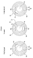
- FIG. 6 shows schematic plane sections of a rotation terminating mechanism of the first embodiment, in which (a) is a diagram in a case where a steering wheel is at a neutral position relative to right and left rotational positions, (b) is a diagram in a case where the steering wheel is fully steered to the left (in a "left rack end” state), and (c) is a diagram in a case where the steering wheel is fully steered to the right (in a "right rack end” state).
- the rotation terminating mechanism 6A is disposed on a steering wheel 3 side relative to the torque sensor 110 in an axial direction of the input shaft 3d, and as shown in FIG. 6 , has a stopper 40 which includes: a rotary stopper 41 in a shape of an approximate cylinder, which is fixed to an outer periphery of the input shaft 3d and has a projection 41a outward protruding from an outer periphery of the rotary stopper 41 in a radial direction; and a fixed stopper 43 in a shape of an approximate cylinder, which is fixed to the inner periphery of the lid portion 13A and has a projection 43a inward protruding from an inner periphery of the fixed stopper 43 in a radial direction.
- the rotary stopper 41 is rotatable approximately 180° to both the right and left in a rotational direction, as an allowable range of operation amount (allowable range of turning operation) of
- the projection 41a is positioned 180° opposite to the projection 43a.
- the rack end 8b and the housing end 11a are provided for the purpose of positioning during assembly of the rack shaft 8, and are configured to have a room therebetween so as not to come into contact with each other, at the steering angle (operation amount) of the steering wheel 3 fully to the right and the left, which is limited by the rotation terminating mechanism 6A. Therefore, even when the rotation of the electric motor 4 undergoes overshoot, the device has a function of reducing the steering torque Ts detected (measured) by the torque sensor 110.
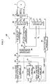
- FIG. 7 is a function diagram of the steering control ECU
- FIG. 8A is a data table showing a relationship in a base signal computing part, between a torque signal as input and a base signal as output
- FIG. 8B is a data table showing a relationship in a damper compensation signal computing part, between a rotational speed of an electric motor as input and a compensation signal as output.
- the steering control ECU 200 includes a microcomputer with components, such as CPU (Central Processing Unit), ROM (Read Only Memory), RAM (Random Access Memory) (all not shown), programs and peripheral circuits and the like, and performs a function depicted in the function diagram of FIG. 7 .
- CPU Central Processing Unit
- ROM Read Only Memory
- RAM Random Access Memory
- the steering control ECU 200 includes: a base signal computing part 220; an inertia compensation signal computing part 210; a damper compensation signal computing part 225; a Q-axis (torque axis) PI control part 240; a D-axis (axis of magnetic pole) PI control part 245; a 2-axis-to-3-phase conversion part 260; a PWM conversion part 270; a 3-phase-to-2-axis conversion part 265; an electric motor speed calculating part 280; and an exciting current generation part 285.
- the 3-phase-to-2-axis conversion part 265 is configured to convert a three-phase current IU, IV, IW of the electric motor 4 detected by the electric motor drive circuit 23 into a two-axis current, including a D-axis which is an axis of magnetic pole of the rotor of the electric motor 4, and a Q-axis which is obtained by electrically rotating the D-axis by 90 degrees.
- a Q-axis current IQ is proportional to the torque T M generated at the electric motor 4, and a D-axis current ID is proportional to an exciting current.
- the electric motor speed calculating part 280 introduces a differential operator to an angular signal ⁇ of the electric motor 4, to thereby generate an angular velocity signal ⁇ M .
- the exciting current generation part 285 generates a target signal "0" for the exciting current of the electric motor 4, and if desired, field-weakening control can be performed by making the D-axis current substantially equal to the Q-axis current.
- the base signal computing part 220 Based on the torque signal VT3 and the vehicle speed signal VS, the base signal computing part 220 generates a base signal D T to be used as a standard reference for a target signal IM of the output torque T M '.
- the signal is generated from a base table 220a with reference to the torque signal VT3 and the vehicle speed signal VS, which table had been prepared in advance by experimental measurement or the like.
- FIG. 8A is a graph showing a function of the base signal D T , stored in the base table 220a.
- a dead zone N1 is provided where the base signal D T is set to zero when the value of the torque signal VT3 is small, and the base signal D T linearly increases along a gain G1 when the value of the torque signal VT3 is larger than the value in the dead zone N1.
- the base signal computing part 220 increases the output along a gain G2 at specific torque values, and when the torque value further increases, the output is made saturated.
- a vehicle body in general has various road loads (road reactions) depending on the running speed thereof. Accordingly, the gain is adjusted based on the vehicle speed signal VS.
- the gains (G1, G2) smaller and the dead zone N1 larger.
- the damper compensation signal computing part 225 is introduced for compensating a viscosity in the steering unit, and for providing a steering damper function for compensating convergence of steering wheel position when convergence decreases during high-speed driving, by reading a damper table 225a with reference to the angular velocity signal ⁇ M .
- FIG. 8B is a graph showing a characteristic function of the damper table 225a, in which the line is formed of a several linear sections and a compensation value I as a whole increases as the angular velocity ⁇ M of the electric motor 4 increases.
- the graph is also characterized in that the compensation value I rapidly increases when the angular velocity ⁇ M is in a specific range.
- the angular velocity of the electric motor 4 i.e., the output torque T M ' of the electric motor 4 in accordance with the speed of the steering wheel turn, is reduced by increasing the gains.
- the damper compensation signal computing part 225 increases the current supply to the electric motor 4, to thereby perform an inhibitory control of the angular velocity ⁇ M when the steering wheel 3 is resuming the home position.
- an adder 251 is configured, when the steering wheel 3 is turned away from the home position, to subtract the output signal of the damper compensation signal computing part 225 from the output signal D T of the base signal computing part 220, and on the other hand, when the steering wheel 3 is returned to resume the home position, to add the output signal of the damper compensation signal computing part 225 to the output signal D T .
- An adder 250 is configured to add the output signal from the adder 251 and the output signal from the inertia compensation signal computing part 210 and to output the output signal IM. It should be noted that a basic assist control is performed by a combination of the base signal computing part 220, the damper compensation signal computing part 225 and the adder 251.
- the inertia compensation signal computing part 210 is configured to compensate an effect caused by the inertia in the steering unit, in which the torque signal VT3 is subjected to computation with reference to an inertia table 210a.
- the inertia compensation signal computing part 210 compensates the lowering of the response caused by the inertia of the rotor of the electric motor 4. To put it another way, when the rotation direction of the electric motor 4 is made to be switched from forward to reverse or vice versa, it is difficult to immediately switch the direction since the inertia tends to maintain the rotational state. Accordingly, the inertia compensation signal computing part 210 controls the timing of switching the rotation direction of the electric motor 4, so as to synchronize the timing of switching the rotation direction of the electric motor 4 with that of the steering wheel 3. In this manner, the inertia compensation signal computing part 210 reduces a response lag in the steering, which may otherwise be caused by inertia, viscosity or the like in the steering unit, to thereby give an excellent steering feeling.
- the inertia compensation signal computing part 210 can practically impart satisfactory steering feeling relative to various steering properties which varies depending on vehicle characteristics, such as those specifically different among FF (Front engine Front wheel drive) vehicle, FR (Front engine Rear wheel drive) vehicle, RV (Recreation Vehicle) and sedan (or saloon) car, and vehicle states, such as vehicle speed, as well as road conditions.
- vehicle characteristics such as those specifically different among FF (Front engine Front wheel drive) vehicle, FR (Front engine Rear wheel drive) vehicle, RV (Recreation Vehicle) and sedan (or saloon) car, and vehicle states, such as vehicle speed, as well as road conditions.
- the output signal IM of the adder 250 is a target signal for the Q-axis current which defines the torque of the electric motor 4 and an adder 252 is configured to subtract the Q-axis current IQ from the output signal IM and to generate a deviation signal IE.
- the Q-axis (torque axis) PI control part 240 is configured to perform a P (proportional) control and an I (integral) control so as to reduce the deviation signal IE.
- An adder 253 is configured to subtract the D-axis current ID from the output signal of the exciting current generation part 285.
- the D-axis (axis of magnetic pole) PI control part 245 is configured to perform a PI feedback control so as to reduce the output signal from the adder 253.
- the 2-axis-to-3-phase conversion part 260 is configured to convert two-axis signal including an output signal VQ from the Q-axis (torque axis) PI control part 240 and an output signal VD from the D-axis (axis of magnetic pole) PI control part 245 into three-phase signal UU, UV, UW.
- the PWM conversion part 270 is configured to generate duty signals (DUTY U, DUTY V, DUTY W), which is an ON/OFF signal [PWM (Pulse Width Modulation) signal] having pulse widths proportional to the magnitude of the three-phase signal UU, UV, UW.
- the angular signal ⁇ of the electric motor 4 is input to the 2-axis-to-3-phase conversion part 260 and the PWM conversion part 270, and signals corresponding to the magnetic pole position of the rotor are output.
- FIG. 1 a case is assumed in which there is no rotation terminating mechanism 6A (in a case of the conventional electric power steering device).
- the conventional electric power steering device when the housing end 11a on a right (or left) end of the rack housing portion 11A and the corresponding rack end 8b of the rack shaft 8 are in contacting engagement with each other, and the steering wheel 3 is further turned to the right (or left), a larger load is applied from the pinion shaft 7 to the rack shaft 8, than a load from the front wheels 1L, 1R.
- the load torque TL from the front wheels 1L, 1R does not further increase, but the torsion bar 111 is further distorted. Accordingly, the steering torque Ts is detected (measured) as a larger value by the torque sensor 110, and the steering control ECU 200 outputs a command to the electric motor drive circuit 23, to increase a current value by the electric motor 4.
- a rotational angular velocity of the electric motor 4 is represented as ⁇ M
- a rotational inertia moment is represented as Im.
- This kinetic energy is absorbed by elastic deformation of the worm gear 5a, the worm wheel gear 5b, the pinion gear 7a, the rack gear 8a, the bearing 3e, 3f, 3g, the rack end 8b, the housing end 11a and the like, and a shock load in this state becomes approximately 1.5 times higher than a normal load in the case where no rack end angle is reached.
- the loads applied to the electric motor 4, the worm gear 5a, the worm wheel gear 5b, the pinion gear 7a, the rack gear 8a, the bearings 3e, 3f, 3g, the rack end 8b and the rack housing portion 11A become approximately twice higher than normal loads.
- the bearings and a module of the gears should be made larger, the rack housing portion 11A should be made thicker, a reinforcing rib should be introduced, and the like, leading to a problem of heavier components.
- the electric motor 4 may be burnt out because of overload.
- the projections 41a, 43a are already brought into contact with each other, so that the input shaft 3d is not further turned away from the home position in the rotation terminating mechanism 6A, and thus the operating force of further turning away of the steering wheel 3 is not transmitted to the torsion bar 111.
- the torsion bar 111 does not suffer distortion other than the distortion by the load torque TL, among the steering torque Ts, the assist amount A H , the pinion torque Tp, and the load torque TL, the relationship as represented by the equation (3) is maintained, and further assist amount A H from the electric motor 4, which may otherwise be generated by turning further away of the steering wheel 3, is not generated.
- the rack end 8b and housing end 11a for positioning has a room above the maximum turning angle of the wheels (rack end angle)
- the steering torque Ts detected (measured) by the torque sensor 110 is reduced, and the assist amount A H is reduced.
- Ts + A H Tp ⁇ TL
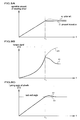
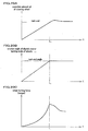
- FIG. 9A is a graph showing changes over time of operation amount of the steering wheel
- FIG. 9B is a graph showing changes over time of a torque signal VT3 output from a torque sensor
- FIG. 9C is a graph showing changes over time in an actual turning angle of front wheels.
- the torque signal continues to increase until the time t1, due to the large change in the operation amount of the steering wheel 3, but at the time t1, the increase in the torque signal stops since the increase in the operation amount of the steering wheel 3 becomes zero.
- a curve z1 in FIG. 9C the turning angle of the front wheels 1L, 1R undergoes overshoot a little more than the rack end angle. Due to this overshoot, the torque signal VT3 is reduced as shown in the curve y1 of FIG. 9B . This overshoot is resulting from a kinetic energy by the inertia moment of the electric motor 4.
- the torque signal VT3 temporarily rises to a large extent, and at the same time, the kinetic energy by the inertia moment of the electric motor 4 generates an impact force in the gears (such as the worm gear 5a, the worm wheel gear 5b, the rack gear 8a and the pinion gear 7a).
- the pinion torque Tp can be reduced as the same level or less of the pinion torque Tp in a normal state in which the rack end angle is not reached.
- the rotation terminating mechanism of the present invention is not limited to the above-mentioned embodiment, and for example, the following various modifications are possible.
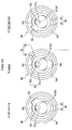
- FIG. 10 shows schematic plane sections of a rotation terminating mechanism of the first modified version of the first embodiment, in which (a) is a diagram in a case where a steering wheel is at a neutral position relative to right and left rotational positions, (b) is a diagram in a case where the steering wheel is fully steered to the left (in a "left rack end” state), and (c) is a diagram in a case where the steering wheel is fully steered to the right (in a "right rack end” state).
- a rotation terminating mechanism 6B is formed of: an inner shaft 51 connected to the input shaft 3d; a rotary stopper 53 disposed outside of the inner shaft 51; and a fixed stopper 54 disposed outside of the rotary stopper 53.
- an external gear 51a On the inner shaft 51, an external gear 51a is provided, and the rotary stopper (ring gear) 53 in a shape of an approximate cylinder having an internal gear 53a formed in an inner periphery, which gear engages with the external gear 51a, is disposed eccentrically relative to the inner shaft 51.
- a ratio in the number of teeth between the external gear 51a and the internal gear 53a is approximately 1:3.
- the rotary stopper 53 has a projection (first projection) 53b outward protruding from a portion of an outer periphery thereof in a radial direction.
- the fixed stopper 54 in a shape of an approximate cylinder, which is fixed to the inner periphery of the lid portion 13A and has a projection (second projection) 54a inward protruding from a portion of an inner periphery of the fixed stopper 54 in a radial direction, is provided coaxially with the rotary stopper 53.
- the rotary stopper 53 and the fixed stopper 54 form a stopper 50.
- the external gear 51a and the internal gear 53a together form a deceleration mechanism 55, and when the steering wheel 3 is rotated by approximately 540° from the neutral state in a right-handed (clockwise) or left-handed (anticlockwise) direction, the rotary stopper 53 is rotated by approximately 180° in the corresponding direction, and the projection 53a is brought into contact with the projection 54a in a rotational direction.
- an entire outer periphery of the upper end portion, as well as an entire outer periphery of the lower end portion, is a cylindrical periphery.
- an entire inner periphery of the upper end portion, as well as an entire inner periphery of the lower end portion is a cylindrical periphery with a small radius.
- the outer cylindrical peripheries of the rotary stopper 53 and the respective inner cylindrical peripheries of the fixed stopper 54 form sliding bearings, and this structure allows the rotary stopper 53 to rotate.
- the projection 53a is positioned 180° opposite to the projection 54a.
- the allowable range of operation amount (allowable range of turning operation) of the steering wheel 3 to the rack end angle becomes as large as 540° in both the right-handed and left-handed (clockwise and anticlockwise) directions. Therefore, the operation amount of the steering wheel 3 can be conveniently made as those of the common vehicle.
- the allowable range of operation amount can be set to, for example, 450°, 600° or the like. In other words, the operation amount of the steering wheel corresponding to the rack end angle can be altered, which allows an introduction of the steering device to various types of vehicles.
- the rotation terminating mechanism 6B blocks the turning operation, and the operating force of further turning away is not transmitted to the torsion bar 111.
- the steering torque Ts, the assist amount A H , the pinion torque Tp, and the load torque TL, the relationship as represented by the equations (3) and (6) is maintained, and the assist amount A H and the steering torque Ts from the electric motor 4, which may otherwise be generated by turning further away of the steering wheel 3, are not generated.
- the worm gear 5a, the worm wheel gear 5b, the pinion gear 7a, the rack gear 8a, the bearings 3e, 3f, 3g, the rack end 8b, and the rack housing portion 11A can be reduced, and the problem of heavier components, such as larger bearings, a larger module of the gears, a thicker rack housing portion 11A, and an introduction of a reinforcing rib, can be solved, which may otherwise be necessary for the conventional components for ensuring the durability.
- size and weight of the components can be reduced, improving the mountability on the vehicle, especially on the compact vehicle.
- a room is created in the current capacity and thus the weight of the electric motor 4 can be reduced.
- the deceleration mechanism 55 according to the first modified version in which the external gear 51a and the internal gear 53a are used in combination is illustrated as one for reducing the operation amount of the steering wheel 3 of approximately 540° in both the right and left directions, to the rotation angle of the rotary stopper 53 of approximately 180° in the corresponding right or left direction.
- any deceleration mechanism may be used.
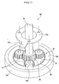
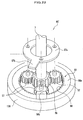
- FIG. 11 is a schematic perspective view showing a rotation terminating mechanism of the second modified version of the first embodiment using a planetary gear reducer unit.
- a planetary gear reducer unit 59 may include: a sun gear 56; planetary gears 57 each configured to engage with the sun gear 56 and revolve around the sun gear 56; an outer ring gear 58 having internal tooth configured to engage with the planetary gear 57; and a planetary carrier 57a configured to connect shafts of the planetary gears 57.
- the input shaft 3d drives the sun gear 56.
- the planetary carrier 57a corresponds to the rotary stopper 53 and for example has a projection (first projection) 57b outward protruding in a radial direction.
- the outer ring gear 58 corresponds to the fixed stopper 54 and is fixed to the lid portion 13A and has a projection (second projection) 58b which protrudes from a portion of an outer rim side of an end face 58a of the outer ring gear 58 in an axial direction (in such a manner that the projection 58b does not interfere with the planetary gear 57), and is configured to engage with the projection 57b.
- the rotation angle of the planetary carrier 57a relative to the rotation angle of the sun gear 56 can be reduced to 1/3, and as in the first modified version of the first embodiment, the rotation angle of the planetary carrier 57a (rotary stopper 53) is reduced to approximately 180° in both the right and left directions, as compared with the allowable range of operation amount (allowable range of turning operation) of the steering wheel 3 of approximately 540° in both the right and left directions.
- the projection 57b is outward protruding from the planetary carrier 57a in a radial direction, but the present invention is not limited to this embodiment, and alternatively, the projection 57b may be protruding in an axial direction (upward in FIG. 11 ), and at the same time the projection 58b may be inward protruding from the end face 58a of the outer ring gear 58 in a radial direction.
- the projection 58b may be inward protruding from the inner periphery of the lid portion 13A in a radial direction, so as to engage with the projection 57b.
- the rotation terminating mechanism 6B' can be made coaxial with a center axis of the lid portion 13A, and thus the size of the rotation terminating mechanism 6B' in a radial direction can be reduced.
- the rotation terminating mechanism 6B' can tolerate a larger load as compared with the case of the rotation terminating mechanism 6B of the second modified version, and thus can be made compact by that amount.
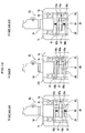
- FIG. 12 shows schematic plane sections of a rotation terminating mechanism of the third modified version of the first embodiment, in which (a) is a diagram in a case where a steering wheel is at a neutral position relative to right and left rotational positions, (b) is a diagram in a case where the steering wheel is fully steered to the left (in a "left rack end” state), and (c) is a diagram in a case where the steering wheel is fully steered to the right (in a "right rack end” state).
- FIG. 13A to 13D are perspective views separately showing components of the rotation terminating mechanism of the third modified version of the first embodiment, in which: FIG. 13A is a perspective exterior view of an upper stopper; FIG. 13B is a perspective exterior view of a rotary stopper fixed to a thread portion; FIG. 13C is a perspective exterior view of a lower stopper; and FIG. 13D is a perspective exterior view of a guide member.
- the rotation terminating mechanism 6C is formed of: a thread portion 61 having an external thread 61a formed in an outer periphery of the input shaft 3d; a rotary stopper (first stopper) 62 in a shape of a cylinder welded to the thread portion 61 at the center thereof in an axial direction; an upper stopper (second stopper) 63 and a lower stopper (third stopper) 65 disposed above and below, respectively, the rotary stopper 62; and a guide member 67.
- the rotary stopper 62 is in a shape of an approximate cylinder as shown in FIG. 13B , and has a projection (first projection) 62a outward protruding from a portion of an outer periphery thereof in a radial direction.
- a distance from the rotational axis of the rotary stopper 62 to the outermost end of the projection 62a in the radial direction is made shorter than a distance from the axis to the inner periphery of the guide member 67.
- the upper stopper 63 and lower stopper 65 is in a shape of an approximate cylinder as shown in FIGs. 13A and 13C .
- the upper stopper 63 includes: an internal thread 63a which is formed in an inner periphery and engages with the external thread 61a; and a guide portion 63b and a projection (second projection) 63c, both outward protruding from a portion of an outer periphery of the upper stopper 63 and arranged 180° opposite to each other.
- the guide portion 63b and the projection 63c fit in their respective guide slits 67b of the guide member 67 each extending in an axial direction, which will be described later.
- the upper stopper 63 is guided by the guide slit 67b and moves up or down in the axial direction.
- the guide portion 63b has the same thickness as that of the cylindrical main body of the upper stopper 63 and is flush with the cylindrical main body.
- the projection 63c is downward protruding in the axial direction, as shown in FIG. 13A .
- the lower stopper 65 is the same as the upper stopper 63 as an article, and is assembled simply upside down in the device, and has the same structure as that of the upper stopper 63.
- a projection 65c of the lower stopper 65 corresponds to a third projection.
- the rotary stopper 62, the upper stopper 63 and the lower stopper 65 form the stopper 60.
- the guide member 67 includes members 67A, 67B each having a shape of a half of a cylinder divided in the axial direction and forming a cylinder as a combination.
- Each of the members 67A, 67B has serrations 67a which extend in the axial direction and are formed in the outer periphery, and has the guide slit 67b which extends in the axial direction and is formed in the center position of the outer periphery.
- the serrations 67a are configured to engage with the serration (not shown) formed in the inner periphery of the lid portion 13A, so as to fix the guide member 67 and prohibit the movement of the guide member 67 in a circumferential direction in the lid portion 13A.
- the guide member 67 has a separable structure, by making the outer diameter of both ends of the thread portion 61 in the radial direction smaller than the inner diameter of the peak of the internal threads 63a, 65a of the stoppers 63, 65, the upper stopper 63 and the lower stopper 65 are first assembled with the thread portion 61 from the bottom and the top thereof, respectively, and then the guide portions 63b, 65b and the projections 63c, 65c are fitted to the respective guide slits 67b of the members 67A, 67B, to thereby assemble the guide member 67 as one unit. Finally, the rotation termination mechanism is fixed by press-fitting the guide member 67 into the inner periphery of the lid portion 13A.
- the external thread 61a, the internal thread 63a and the internal thread 65a together form a deceleration mechanism, and when the steering wheel 3 is rotated by approximately 540° from the neutral state in a right-handed (clockwise) or left-handed (anticlockwise) direction, the rotary stopper 62 is rotated by approximately 540° in the corresponding direction, and the upper stopper 63 and the lower stopper 65 move by the same distance in an axial direction. For example, the upper stopper 63 and the lower stopper 65 moves upward when the steering wheel 3 is steered to the left and downward when steered to the right.
- the projection 62a comes into contact with the projection 65c in the case of the steering to the left, and with the projection 63c in the case of the steering to the right, in a rotational direction.
- the allowable range of operation amount (allowable range of turning operation) of the steering wheel 3 of approximately 540° in both the right and left rotational direction is ensured.
- the allowable range of operation amount can be set to, for example, 2 turns (720°) to both the right and left, and thus the device can be applied to vehicles other than automobile.
- FIG. 12 shows that, when the steering wheel 3 is at a neutral position, the projection 62a is positioned at a center in an axial direction relative to the projections 63c, 65c.
- (b) shows that, in the "left rack end” state where the rack shaft 8 is fully steered to the left and thus the rack end 8b and the housing end 11a are brought into contact with each other, the projection 62a comes into contact with the projection 65c in an anticlockwise direction (seen from above), and thus even when the steering wheel 3 is turned further to the left, further rotation or operating force is not transmitted to the torsion bar 111.
- (c) shows that, in the "right rack end” state where the rack shaft 8 is fully steered to the right and thus the rack end 8b and the housing end 11a are brought into contact with each other, the projection 62a comes into contact with the projection 63c in a clockwise direction (seen from above), and thus even when the steering wheel 3 is turned further to the right, further rotation or operating force is not transmitted to the torsion bar 111.
- the rotation terminating mechanism 6C blocks the turning operation, and the operating force of further turning away is not transmitted to the torsion bar 111.
- the steering torque Ts, the assist amount A H , the pinion torque Tp, and the load torque TL, the relationship as represented by the equations (3) and (6) is maintained, and the assist amount A H and the steering torque Ts from the electric motor 4, which may otherwise be generated by turning further away of the steering wheel 3, are not generated.
- the electric power steering device 100A in the first embodiment is configured to perform assist drive of the pinion shaft 7 through the deceleration mechanism 5A by the electric motor 4.
- the torque sensor described above is one configured to convert a torsion angle of the torsion bar 111 into a vertical displacement amount of the slider 115, detect (measure) the displacement amount by the detection coils 114A, 114B, and output a torque signal VT3.
- any torque sensor may be used.
- FIG. 14 is a configuration diagram of an electric power steering device according to the second embodiment of the present invention.
- An electric power steering device 100B of the present embodiment is configured to perform assist driving of the rack shaft 8 by the electric motor 4, through a ball screw 5c.
- the present embodiment is different from the first embodiment in that the electric motor 4 drives the deceleration mechanism (auxiliary torque transmission mechanism) 5B formed of the worm gear 5a and the worm wheel gear 5b, and the ball screw 5c, to thereby directly convert a rotational motion of the ball screw 5c to a linear motion of the rack shaft 8, unlike the first embodiment in which the electric motor 4 drives the pinion shaft 7 through the worm gear 5a and the worm wheel gear 5b.
- the electric motor 4 drives the pinion shaft 7 through the worm gear 5a and the worm wheel gear 5b.
- the present embodiment is different from the first embodiment in that a torque sensor 120 with magnetostrictive film is used, instead of the torque sensor 110.
- the torque sensor 120 has the same structure as that disclosed in FIGs. 1 and 2 of Japanese unexamined patent publication No. 2006-322952 , and the outer periphery of the input shaft 3d is covered with a magnetostrictive material showing a positive magnetostriction constant, such as Fe-Ni or Fe-Cr material with a predetermined film thickness, such as 30 micrometer or less by plating, vapor deposition or the like, in a whole circumferential direction.
- the films are formed at two positions with a predetermined interval in an axial direction, as a first magnetostrictive film 121A and a second magnetostrictive film 121B.
- the film is formed in such a manner that first the film is heated by high-frequency induction heating and cooled to room temperature while a predetermined torque is applied to the input shaft 3d, and then the torque is removed, in order to create magnetic anisotropy in opposite directions in these films. Due to this property, even when the torsion torque is not applied to the magnetostrictive films 121A, 121B, the tensile stress and tensile distortion are always put, and hysteresis in inverse magnetostriction property becomes small. In addition, unlike the torque sensor 110 of the first embodiment, the electric power steering device of the present embodiment does not have the torsion bar 111 and thus distortion is not generated.
- the steering angle of the steering wheel 3 corresponds to the turning angle of the wheels of the front wheels 1L, 1R, without distortion difference.
- a range of the turning angle of the wheels corresponding to the allowable range of operation amount determined by the rotation terminating mechanism 6 becomes substantially large.
- an exciting coil (not shown) of the torque sensor 120 is placed with a common minute gap from the magnetostrictive films 121A, 121B, and a first detection coil 124A is disposed corresponding to the first magnetostrictive film 121A and a second detection coil 124B is disposed corresponding to the second magnetostrictive film 121B, with a minute gap at positions 90° away from the exciting coil in an circumferential direction.
- the torque sensor 120 when a torque is applied to the input shaft 3d, the torque is also applied to the magnetostrictive films 121A, 121B where inverse magnetostriction effect is generated in accordance with the applied torque.
- an alternating voltage (exciting voltage) with high-frequency wave is supplied from an exciting voltage supply source (not shown) to the exciting coil, a change in a magnetic field due to an inverse magnetostriction effect based on a torque applied to the magnetostrictive films 121A, 121B can be detected as a change in impedance or induction voltage, by the detection coils 124A, 124B.
- the tensile stress is always applied to the magnetostrictive films 121A, 121B, the hysteresis becomes small, and from this change in impedance or induction voltage, the torque applied to the input shaft 3d can be detected (measured).
- the signal voltage VT1, VT2 from the detection coils 124A, 124B, respectively, are amplified by the differential amplifier 21, and output as a torque signal VT3 to the steering control ECU 200.
- the rotation terminating mechanism 6 is disposed on a steering wheel 3 side relative to the torque sensor 120 in an axial direction of the input shaft 3d.
- the rotation terminating mechanism 6 is illustrated as one representing the above-mentioned rotation terminating mechanisms 6A, 6B, 6B', 6C, and any of the rotation terminating mechanisms 6A, 6B, 6B', 6C can be used.
- the rotation terminating mechanism 6 blocks the turning operation, and the operating force of further turning away is not transmitted to the magnetostrictive films 121A, 121B of the torque sensor 120.
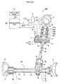
- FIG. 15 is a configuration diagram of an electric power steering device according to the third embodiment of the present invention.
- An electric power steering device 100C of the present embodiment is configured to perform assist driving of the steering wheel shaft 3a by the electric motor 4, through the worm gear 5a and worm wheel gear 5b.
- the present embodiment is different from the first embodiment in that the electric motor 4 drives the steering wheel shaft 3a through the deceleration mechanism (auxiliary torque transmission mechanism) 5A formed of the worm gear 5a and the worm wheel gear 5b, unlike the first embodiment in which the electric motor 4 drives the pinion shaft 7 through the worm gear 5a and the worm wheel gear 5b.
- the electric motor 4 drives the steering wheel shaft 3a through the deceleration mechanism (auxiliary torque transmission mechanism) 5A formed of the worm gear 5a and the worm wheel gear 5b, unlike the first embodiment in which the electric motor 4 drives the pinion shaft 7 through the worm gear 5a and the worm wheel gear 5b.
- the present embodiment is different from the first embodiment in that a torque sensor 120 with magnetostrictive film is used, instead of the torque sensor 110.
- a column housing 15 containing the steering wheel shaft 3a of the steering wheel 3, and the pinion shaft 7 upward extending from a lid portion 13C of a steering gear box 10C are connected through a shaft 3c and two universal joints 3b.
- the column housing 15 contains: the bearing 3e below a seal 3h provided on the upper end of the column housing 15; and below the bearing 3e, the rotation terminating mechanism 6, the torque sensor 120, a bearing 3i, the worm wheel gear 5b and a bearing 3j in this order.
- An output shaft 3k which is a lower end of the steering wheel shaft 3a downward extending from a lower end of the column housing 15, is connected to the universal joint 3b.
- the left front wheel 1L and the right front wheel 1R are connected through tie rods 9, 9.
- the torque sensor 120 of the present embodiment has substantially the same structure as that of the torque sensor 120 in the second embodiment, except that the torque sensor 120 is contained in the column housing 15, the first magnetostrictive film 121A and the second magnetostrictive film 121B are formed on an outer periphery of the steering wheel shaft 3a, and an exciting coil (not shown) and the detection coils 124A, 124B are placed with a minute gap from the magnetostrictive films 121A, 121B.
- the rotation terminating mechanism 6 is disposed on a steering wheel 3 side relative to the torque sensor 120 in an axial direction of the steering wheel shaft 3a.
- the rotation terminating mechanism 6 is illustrated as one representing the above-mentioned rotation terminating mechanisms 6A, 6B, 6B', 6C, and any of the rotation terminating mechanism 6A, 6B, 6B', 6C can be used.
- the rotation terminating mechanism 6 blocks the turning operation, and the operating force of further turning away is not transmitted to the magnetostrictive films 121A, 121B of the torque sensor 120.
- the rotation terminating mechanism 6 is provided near the steering wheel 3, the centering of the steering wheel shaft 3a of the steering wheel 3 with the rotation terminating mechanism 6 is facilitated.
- an electric power steering device 100D of the present embodiment has substantially the same structure as that of the electric power steering device 100A of the first embodiment (see FIGs. 1 , 2 and 4 ), except that the position of the rotation terminating mechanism is different.
- Components which are the same as those illustrated in the first embodiment are designated with the same reference characters, and thus a duplicate description is omitted.
- a rotation terminating mechanism 6D is disposed between the torque sensor 110 and the worm wheel gear 5b, in an axial direction of the input shaft 3d.
- the projection 41a is positioned 180° opposite to the projection 43a.
- FIG. 16 a case is assumed in which there is no rotation terminating mechanism 6D (in a case of the conventional electric power steering device).
- the conventional electric power steering device when the housing end 11a on a right (or left) end of the rack housing portion 11A and the corresponding rack end 8b of the rack shaft 8 are in contacting engagement with each other, and the steering wheel 3 is further turned to the right (or left), a larger load is applied from the pinion shaft 7 to the rack shaft 8, than a load from the front wheels 1L, 1R.
- a rotational angular velocity of the electric motor 4 is represented as ⁇ M
- a rotational inertia moment is represented as Im.
- the kinetic energy is absorbed by elastic deformation of the worm gear 5a, the worm wheel gear 5b, the pinion gear 7a, the rack gear 8a, the bearings 3e, 3f, 3g, the rack end 8b, the housing end 11a and the like, and overload in this state becomes approximately 1.5 times higher than a normal load in the case where no rack end angle is reached.
- the loads applied to the electric motor 4, the worm gear 5a, the worm wheel gear 5b, the pinion gear 7a, the rack gear 8a, the bearings 3e, 3f, 3g, the rack end 8b and the rack housing portion 11A become approximately 1.5 times higher than normal loads.
- the bearings and a module of the gears should be made larger, the rack housing portion 11A should be made thicker, a reinforcing rib should be introduced, and the like, leading to a problem of heavier components.
- the projections 41a, 43a are already brought into contact with each other, so that the pinion shaft 7 is not further turned away from the home position in the rotation terminating mechanism 6D. Accordingly, an impact force by the inertia moment (kinetic energy) of the electric motor 4 is absorbed by the contact between the projection 41a and the projection 43a of the rotation terminating mechanism 6D and is never transmitted to the pinion gear 7a, the rack gear 8a, the rack shaft 8, the rack end 8b, the housing end 11a and the like through the pinion shaft 7.
- the rotation terminating mechanism 6D is disposed on a torque sensor side (upstream side) of the deceleration mechanism (auxiliary torque transmission mechanism) 5A, the auxiliary torque of the electric motor 4 does not affect on the rotation terminating mechanism 6D, and as compared with a case where the rotation terminating mechanism 6D is disposed on a rack-and-pinion gears side (downstream side) of the deceleration mechanism (auxiliary torque transmission mechanism) 5A, the rotation terminating mechanism 6D, specifically the stopper 40, can be made compact. As a result, the stopper 40, the rotation terminating mechanism 6D and thus the electric power steering device 100D can be made compact.
- FIG. 20A is a graph showing changes over time of operation amount of the steering wheel
- FIG. 20B is a graph showing changes over time of rotation angle of an electric motor (solid line) and turning angle of front wheels (dotted line), overlapped each other
- FIG. 20C is a graph showing changes over time in wheel turning force (torque) of front wheels.
- the rotation angle (solid line) of the electric motor 4 and the turning angle of front wheels (dotted line) continue to increase until the time t1, due to the large change in the operation amount of the steering wheel 3, but at the time t1, the projections 41a, 43a of the rotation terminating mechanism 6D are brought into contact with each other, since the rotation angle of the electric motor 4 and the turning angle of front wheels reach the rack end angle. Therefore, after the time t1, the rotation angle of the electric motor 4 and the turning angle of front wheels become constant at the rack end angle without increasing, such as overshoot, regardless of the time t.
- the wheel turning force (torque) of the front wheels 1L, 1R increases until the time t1, but after the time t1, since the projections 41a, 43a of the rotation terminating mechanism 6D are brought into contact with each other, a wheel turning force (torque) exceeding the wheel turning force (torque) at the time t1 is never generated, and the generation of the overload can be prevented. Then, the rack-and-pinion gears never suffer the effect of the inertia moment of the electric motor 4, such as an impact force.
- the overload generated in the pinion gear 7a, the rack gear 8a, the rack shaft 8, the rack end 8b, the housing end 11a, and the rack housing portion 11A can be prevented, and thus the pinion torque Tp actually transmitted to the pinion gear 7a and rack gear 8a can be reduced to the same level or less of the pinion torque Tp in a normal state in which the rack end angle is not reached.
- loads (overload) assumed upon designing the pinion gear 7a, the rack gear 8a, the bearings 3e, 3f, 3g, the rack end 8b and the rack housing portion 11A can be reduced, and the problem of heavier components, such as larger bearings, a larger module of the gears, a thicker rack housing portion 11A, and an introduction of a reinforcing rib, can be solved, which may otherwise be necessary for the conventional components for ensuring the durability.
- size and weight of the components can be reduced, improving the mountability on the vehicle, especially on the compact vehicle.
- the rotation terminating mechanism of the present invention is not limited to the above-mentioned embodiment, and for example, the following various modifications are possible.
- a rotation terminating mechanism 6E is formed of: the inner shaft 51 as a part of the pinion shaft 7 (specifically called so in this rotation terminating mechanism 6E); the rotary stopper 53 disposed outside of the inner shaft 51; and the fixed stopper 54 disposed outside of the rotary stopper 53.
- the present embodiment has substantially the same structure as that of the first modified version of the first embodiment, except that the position of the rotation terminating mechanism is different and thus the input shaft 3d (see FIG. 10 ) is replaced with the pinion shaft 7 in the drawings.
- Components which are the same as those illustrated in the first modified version of the first embodiment are designated with the same reference characters, and thus a duplicate description is omitted.
- the projection 53a is positioned 180° opposite to the projection 54a.
- the allowable range of operation amount (allowable range of turning operation) of the steering wheel 3 to the rack end angle becomes as large as 540° in both the right-handed and left-handed (clockwise and anticlockwise) directions. Therefore, the operation amount of the steering wheel 3 can be conveniently made as those of the common vehicle.
- the allowable range of operation amount can be set to, for example, 450°, 600° or the like. In other words, the operation amount of the steering wheel corresponding to the rack end angle can be altered, which allows an introduction of the steering device to various types of vehicles.
- loads (overload) assumed upon designing the pinion gear 7a, the rack gear 8a, the bearings 3e, 3f, 3g, the rack end 8b and the rack housing portion 11A can be reduced, and the problem of heavier components, such as larger bearings, a larger module of the gears, a thicker rack housing portion 11A, and an introduction of a reinforcing rib, can be solved, which may otherwise be necessary for the conventional components for ensuring the durability.
- size and weight of the components can be reduced, improving the mountability on the vehicle, especially on the compact vehicle.
- FIG. 22 is a schematic perspective view showing a rotation terminating mechanism of a second modified version of the fourth embodiment using a planetary gear reducer unit.
- the present embodiment has substantially the same structure as that of the second modified version of the first embodiment, except that the position of the rotation terminating mechanism is different and thus that the input shaft 3d (see FIG. 11 ) is replaced with the pinion shaft 7 in the drawings.
- Components which are the same as those illustrated in the second modified version of the first embodiment are designated with the same reference characters, and thus a duplicate description is omitted.
- the rotation terminating mechanism 6E' can be made coaxial with a center axis of the lid portion 13A, and thus the size of the rotation terminating mechanism 6E' in a radial direction can be reduced.
- the rotation terminating mechanism 6E' can tolerate a larger load as compared with the case of the rotation terminating mechanism 6E of the second modified version, and thus can be made compact by that amount.
- FIG. 23 shows schematic plane sections of a rotation terminating mechanism of a third modified version of the fourth embodiment.
- the present embodiment has substantially the same structure as that of the third modified version of the first embodiment (see FIG. 12 ), except that the position of the rotation terminating mechanism is different and thus that the input shaft 3d (see FIG. 13B ) is replaced with the pinion shaft 7 in the drawings.
- Components which are the same as those illustrated in the third modified version of the first embodiment are designated with the same reference characters, and thus a duplicate description is omitted.
- FIG. 23 shows that, when the steering wheel 3 is at a neutral position, the projection 62a is positioned at a center in an axial direction relative to the projections 63c, 65c.
- (b) shows that, in the "left rack end” state where the rack shaft 8 is fully steered to the left and thus the rack end 8b and the housing end 11a are brought into contact with each other, the projection 62a comes into contact with the projection 65c in an anticlockwise direction (seen from above), and thus the steering wheel 3 cannot be turned further to the left.
- (c) shows that, in the "right rack end” state where the rack shaft 8 is fully steered to the right and thus the rack end 8b and the housing end 11a are brought into contact with each other, the projection 62a comes into contact with the projection 63c in a clockwise direction (seen from above), and thus the steering wheel 3 cannot be turned further to the right.
- the rotation terminating mechanism 6F blocks the turning operation.
- loads (overload) assumed upon designing the pinion gear 7a, the rack gear 8a, the bearings 3e, 3f, 3g, the rack end 8b and the rack housing portion 11A can be reduced, and the problem of heavier components, such as larger bearings, a larger module of the gears, a thicker rack housing portion 11A, and an introduction of a reinforcing rib, can be solved, which may otherwise be necessary for the conventional components for ensuring the durability.
- size and weight of the components can be reduced, improving the mountability on the vehicle, especially on the compact vehicle.
- the torque sensor described above is one configured to convert a torsion angle of the torsion bar 111 into a vertical displacement amount of the slider 115, detect (measure) the displacement amount by the detection coils 114A, 114B, and output a torque signal VT3.
- any torque sensor may be used.
- an electric power steering device 100E of the present embodiment has substantially the same structure as that of the electric power steering device 100C of the third embodiment (see FIG. 15 ), except that the position of the rotation terminating mechanism is different.
- Components which are the same as those illustrated in the third embodiment are designated with the same reference characters, and thus a duplicate description is omitted.
- the column housing 15 contains the torque sensor 120, the rotation terminating mechanism 6, the bearing 3i, the worm wheel gear 5b and the bearing 3j, in this order.
- the rotation terminating mechanism 6 is disposed between the torque sensor 120 and the worm wheel gear 5b (deceleration mechanism (auxiliary torque transmission mechanism) 5A), in the axial direction of the steering wheel shaft 3a.
- the rotation terminating mechanism 6 is illustrated as one representing the above-mentioned rotation terminating mechanisms 6D, 6E, 6E', 6F, and any of the rotation terminating mechanisms 6D, 6E, 6E', 6F can be used.
- the rotation terminating mechanism 6 blocks the turning operation.
- the rotation terminating mechanism 6 is provided near the steering wheel 3, the centering of the steering wheel shaft 3a of the steering wheel 3 with the rotation terminating mechanism 6 is facilitated.
- loads (overload) assumed upon designing the pinion gear 7a, the rack gear 8a, the bearings 3e, 3f, 3g, the rack end 8b and the rack housing portion 11A can be reduced, and the problem of heavier components, such as larger bearings, a larger module of the gears, and a thicker rack housing portion 11A, and an introduction of a reinforcing rib, can be solved, which may otherwise be necessary for the conventional components for ensuring the durability.
- size and weight of the components can be reduced, improving the mountability on the vehicle, especially on the compact vehicle.
- the rotation terminating mechanism is illustrated as one disposed on the member (such as the input shaft 3d and the steering wheel shaft 3a) between the steering wheel 3 and the pinion shaft 7.
- the rotation terminating mechanism may be disposed on the pinion shaft 7.
Claims (10)
- Dispositif de direction à assistance électrique à pignon et crémaillère qui braque les roues avant (100) comprenant :un opérateur (3), de préférence un volant,un moteur électrique (4) configuré pour générer un couple auxiliaire en fonction d'au moins un couple de braquage généré par une entrée de l'opérateur (3) ;une unité de braquage de roues avant comprenant un arbre de pignon (7) auquel le couple auxiliaire est transmis ;un mécanisme de terminaison de rotation (6) qui fournit une extrémité de terminaison de mouvement de l'opérateur (3), et qui régule un premier angle de braquage maximum appliqué par l'opérateur, le mécanisme de terminaison de rotation (6) étant disposé entre l'opérateur (3) et un capteur de couple qui détecte le couple de braquage ; etun mécanisme de régulation d'angle de braquage qui régule un deuxième angle de braquage maximum des roues avant, le mécanisme de régulation d'angle de braquage étant disposé entre le capteur de couple et les roues avant, dans lequelle dispositif de direction à assistance électrique à pignon et crémaillère (100) braque les roues avant en déplaçant l'arbre de crémaillère dans une direction d'axe de l'arbre de crémaillère en fonction du couple de braquage et du couple auxiliaire, caractérisé en ce quele premier angle de braquage maximum régulé par le mécanisme de terminaison de rotation est fixé de manière à être inférieur au deuxième angle de braquage maximum régulé par le mécanisme de régulation d'angle de braquage.
- Dispositif de direction à assistance électrique à pignon et crémaillère selon la revendication 1, dans lequel le mécanisme de régulation d'angle de braquage est un élément pour réguler un déplacement de l'arbre de crémaillère dans la direction d'axe de l'arbre de crémaillère, et
le premier angle de braquage maximum régulé par le mécanisme de terminaison de rotation est fixé de manière à être inférieur au deuxième angle de braquage maximum régulé par l'élément. - Dispositif de direction à assistance électrique à pignon et crémaillère selon la revendication 1, dans lequel le mécanisme de régulation d'angle de braquage est un mécanisme d'extrémité de crémaillère qui comprend une extrémité de logement agencée sur un logement pour recevoir l'arbre de crémaillère et une extrémité de crémaillère agencée sur l'arbre de crémaillère, et
le premier angle de braquage maximum régulé par le mécanisme de terminaison de rotation est fixé de manière à être inférieur au deuxième angle de braquage maximum régulé par le mécanisme d'extrémité de crémaillère. - Dispositif de direction à assistance électrique (100) selon la revendication 1, dans lequel le mécanisme de terminaison de rotation (6) comprend un mécanisme de décélération et est configuré pour modifier une plage autorisée d'opération de rotation de l'opérateur (3) limitée par l'extrémité de terminaison de mouvement.
- Dispositif de direction à assistance électrique (100) selon la revendication 1, comprenant en outre un capteur de couple (110) configuré pour détecter le couple de braquage,
dans lequel l'unité de braquage des roues avant comprend en outre un mécanisme de transmission de couple auxiliaire, et
le mécanisme de terminaison de rotation (6) est disposé entre le capteur de couple (110) et le mécanisme de transmission de couple auxiliaire. - Dispositif de direction à assistance électrique (100) selon la revendication 1, dans lequel
le mécanisme de terminaison de rotation (6) comprend :un arbre d'entrée (3d) avec un pignon externe (51a), auquel une rotation d'un arbre rotatif de l'opérateur (3) est transmise ;une couronne (53) comportant un pignon interne (53a) configuré pour être accouplé avec le pignon externe (51a) de l'arbre d'entrée (3d) et comportant une première protubérance (53b) sur une périphérie extérieure de la couronne (53) ; etune partie fixe (54) de forme annulaire entourant la couronne (53),dans lequelle pignon externe (51a) de l'arbre d'entrée (3d) et le pignon interne (53a) de la couronne (53) servent en tant que mécanisme de décélération, etune deuxième protubérance (54a) configurée pour limiter une rotation de la première protubérance (53b) en étant mise en contact avec la première protubérance (53b) est prévue sur une périphérie intérieure de la partie fixe (54). - Dispositif de direction à assistance électrique (100) selon la revendication 1, dans lequel
le mécanisme de terminaison de rotation (6) comprend :une unité de réduction à train épicycloïdal (59) en tant que mécanisme de décélération comprenant une couronne extérieure (58), des satellites (57), un porte-satellites (57a) et un planétaire (56), etune partie fixe pour fixer la couronne extérieure (58),dans lequelune première protubérance (57b) est prévue sur le porte-satellites (57a),une rotation d'un arbre rotatif de l'opérateur (3) est transmise au planétaire (56), etune deuxième protubérance (58b) configurée pour limiter une rotation de la première protubérance (57b) en étant mise en contact avec la première protubérance (57b) est prévue sur au moins l'une de la partie fixe et de la couronne extérieure (58). - Dispositif de direction à assistance électrique (100) selon la revendication 1, dans lequel
le mécanisme de terminaison de rotation (6) comprend :une partie filetée (61) avec un filetage externe (61a), à laquelle une rotation d'un arbre rotatif de l'opérateur (3) est transmise ;une première butée (62) de forme annulaire qui comporte une première protubérance (62a) sur une périphérie extérieure de la première butée (62) et qui est fixée à la partie filetée (61) ;une deuxième butée (63) qui comporte un filetage interne (63a) configurée pour s'accoupler avec la partie filetée (61) est disposée au-dessus de la première butée (62), et comporte une deuxième protubérance (63c) configurée pour être mise en contact avec la première protubérance (62a) et formée dans une face inférieure de la deuxième butée (63) ;une troisième butée (65) qui comporte un filetage interne (65a) configurée pour s'accoupler avec la partie filetée (61) est disposée au-dessous de la première butée (62), et comporte une troisième protubérance (65c) configurée pour être mise en contact avec la première protubérance (62a) et formée dans une face supérieure de la troisième butée (65) ; etun élément de guidage (67) configuré pour limiter les rotations des deuxième et troisième butées (63, 65) et déplacer les deuxième et troisième butées (63, 65) le long d'une direction axiale de la partie filetée (61),dans lequella partie filetée (61), la deuxième butée (63), la troisième butée (65) et l'élément de guidage (67) servent en tant que mécanisme de décélération. - Dispositif de direction à assistance électrique (100) selon l'une quelconque des revendications précédentes, dans lequel le capteur de couple (110) est un capteur de couple magnétostrictif (120).
- Dispositif de direction à assistance électrique (100) selon l'une quelconque des revendications précédentes, dans lequel le mécanisme de régulation d'angle de braquage est un mécanisme d'extrémité de crémaillère qui comprend une extrémité de logement (11a) agencé sur une partie de logement de crémaillère (11A) pour recevoir l'arbre de crémaillère (8) et une extrémité de crémaillère (8b) agencée sur l'arbre de crémaillère, et dans lequel l'extrémité de crémaillère (8b) et l'extrémité de logement (11a) sont configurées pour avoir un espace entre elles de manière à ne pas venir en contact l'une avec l'autre à une extrémité de terminaison de mouvement de l'opérateur (3) fournie par le mécanisme de terminaison de rotation (6).
Priority Applications (1)
| Application Number | Priority Date | Filing Date | Title |
|---|---|---|---|
| EP11172898.6A EP2374691B1 (fr) | 2007-11-06 | 2008-11-04 | Dispositif à direction assistée électrique |
Applications Claiming Priority (2)
| Application Number | Priority Date | Filing Date | Title |
|---|---|---|---|
| JP2007288070A JP4783352B2 (ja) | 2007-11-06 | 2007-11-06 | ラックアンドピニオン式電動パワーステアリング装置 |
| JP2008221214A JP5271007B2 (ja) | 2008-08-29 | 2008-08-29 | 電動パワーステアリング装置 |
Related Child Applications (2)
| Application Number | Title | Priority Date | Filing Date |
|---|---|---|---|
| EP11172898.6A Division-Into EP2374691B1 (fr) | 2007-11-06 | 2008-11-04 | Dispositif à direction assistée électrique |
| EP11172898.6A Division EP2374691B1 (fr) | 2007-11-06 | 2008-11-04 | Dispositif à direction assistée électrique |
Publications (2)
| Publication Number | Publication Date |
|---|---|
| EP2058210A1 EP2058210A1 (fr) | 2009-05-13 |
| EP2058210B1 true EP2058210B1 (fr) | 2012-08-29 |
Family
ID=40254377
Family Applications (2)
| Application Number | Title | Priority Date | Filing Date |
|---|---|---|---|
| EP11172898.6A Expired - Fee Related EP2374691B1 (fr) | 2007-11-06 | 2008-11-04 | Dispositif à direction assistée électrique |
| EP08168251A Expired - Fee Related EP2058210B1 (fr) | 2007-11-06 | 2008-11-04 | Dispositif de direction électrique |
Family Applications Before (1)
| Application Number | Title | Priority Date | Filing Date |
|---|---|---|---|
| EP11172898.6A Expired - Fee Related EP2374691B1 (fr) | 2007-11-06 | 2008-11-04 | Dispositif à direction assistée électrique |
Country Status (2)
| Country | Link |
|---|---|
| US (1) | US8066092B2 (fr) |
| EP (2) | EP2374691B1 (fr) |
Families Citing this family (41)
| Publication number | Priority date | Publication date | Assignee | Title |
|---|---|---|---|---|
| KR200470045Y1 (ko) | 2008-12-16 | 2013-11-25 | 엘지이노텍 주식회사 | 일렉트릭 파워 스티어링 시스템 |
| DE102011000434B4 (de) * | 2011-02-01 | 2020-02-27 | Robert Bosch Automotive Steering Gmbh | Verfahren und Vorrichtung zum Abgleichen eines ermittelten Lenkwinkels mit einem gemessenen Lenkwinkel |
| KR101452559B1 (ko) * | 2011-12-06 | 2014-10-21 | 주식회사 만도 | 피니언 센서 어셈블리와 피니언 센서 커버 어셈블리 및 이를 구비한 전동식 동력 보조 조향장치 |
| WO2013094097A1 (fr) * | 2011-12-22 | 2013-06-27 | 日産自動車株式会社 | Dispositif de commande de direction de véhicule et procédé de commande de direction |
| JP5811402B2 (ja) * | 2011-12-26 | 2015-11-11 | 株式会社ジェイテクト | 操舵装置 |
| DE102012107211B4 (de) * | 2012-01-10 | 2016-07-14 | Tedrive Steering Systems Gmbh | Servolenkbaugruppe mit Differenzwinkelsensorik |
| KR20130090987A (ko) * | 2012-02-07 | 2013-08-16 | 주식회사 만도 | 전동식 조향 장치 및 그 제어방법 |
| JP6115757B2 (ja) * | 2012-02-17 | 2017-04-19 | 株式会社ジェイテクト | 車両用操舵装置 |
| JP5880953B2 (ja) * | 2012-03-22 | 2016-03-09 | 株式会社ジェイテクト | 車両用操舵装置 |
| US8924082B2 (en) * | 2012-03-30 | 2014-12-30 | Steering Solutions Ip Holding Corporation | System and method for controlling a motor |
| CN102774268B (zh) * | 2012-07-14 | 2015-09-09 | 盐城工学院 | 一种可实现大角度转向的等长双横臂悬架轮边驱动装置 |
| KR101361395B1 (ko) * | 2012-08-08 | 2014-02-11 | 주식회사 만도 | 차량의 스티어링 시스템에 사용되는 작동장치 |
| US9663139B2 (en) | 2013-02-26 | 2017-05-30 | Steering Solutions Ip Holding Corporation | Electric motor feedforward control utilizing dynamic motor model |
| JP6036407B2 (ja) * | 2013-02-27 | 2016-11-30 | 株式会社ジェイテクト | 電動パワーステアリング装置 |
| US9136785B2 (en) | 2013-03-12 | 2015-09-15 | Steering Solutions Ip Holding Corporation | Motor control system to compensate for torque ripple |
| US9143081B2 (en) | 2013-03-14 | 2015-09-22 | Steering Solutions Ip Holding Corporation | Motor control system having bandwidth compensation |
| US10389289B2 (en) | 2014-02-06 | 2019-08-20 | Steering Solutions Ip Holding Corporation | Generating motor control reference signal with control voltage budget |
| US9393988B2 (en) * | 2014-03-27 | 2016-07-19 | Showa Corporation | Arm stopper mechanism and steering apparatus using same |
| US10003285B2 (en) | 2014-06-23 | 2018-06-19 | Steering Solutions Ip Holding Corporation | Decoupling current control utilizing direct plant modification in electric power steering system |
| JP2016064790A (ja) * | 2014-09-25 | 2016-04-28 | 株式会社ショーワ | ステアリング装置 |
| US9809247B2 (en) | 2015-01-30 | 2017-11-07 | Steering Solutions Ip Holding Corporation | Motor control current sensor loss of assist mitigation for electric power steering |
| JP6411256B2 (ja) * | 2015-03-19 | 2018-10-24 | 本田技研工業株式会社 | 磁歪式トルクセンサ及び電動パワーステアリング装置 |
| KR101658313B1 (ko) * | 2015-05-19 | 2016-09-20 | 주식회사 만도 | 자동차의 조향장치 |
| JP6569387B2 (ja) * | 2015-08-21 | 2019-09-04 | 株式会社デンソー | センサ装置、および、これを用いた電動パワーステアリング装置 |
| DE102015120207A1 (de) * | 2015-11-23 | 2017-05-24 | Robert Bosch Automotive Steering Gmbh | Lenkeinrichtung für ein kraftfahrzeug |
| CN106275058B (zh) * | 2016-08-25 | 2018-06-05 | 青岛科技大学 | 一种车辆线控转向装置 |
| US10135368B2 (en) | 2016-10-01 | 2018-11-20 | Steering Solutions Ip Holding Corporation | Torque ripple cancellation algorithm involving supply voltage limit constraint |
| US10895278B2 (en) * | 2017-02-23 | 2021-01-19 | Mando Corporation | Apparatus for limiting rotation of steering wheel |
| KR102262140B1 (ko) * | 2017-07-12 | 2021-06-10 | 현대자동차주식회사 | 스티어 바이 와이어 시스템용 조향장치 |
| JP2019023038A (ja) * | 2017-07-24 | 2019-02-14 | 株式会社ジェイテクト | 操舵制御装置 |
| US20190092373A1 (en) * | 2017-09-28 | 2019-03-28 | Dura Operating, Llc | Steering control assembly for a vehicle steer-by-wire system |
| DE102017220929B4 (de) * | 2017-11-23 | 2020-02-27 | Robert Bosch Gmbh | Verfahren zum Betreiben eines Lenksystems und Lenksystem |
| JP6393858B1 (ja) | 2018-06-12 | 2018-09-19 | 株式会社ショーワ | 舵角規制装置 |
| KR102575396B1 (ko) * | 2018-06-21 | 2023-09-07 | 현대자동차주식회사 | Sbw시스템의 조향각 제한장치 |
| GB2575994B (en) * | 2018-07-31 | 2022-08-10 | Zf Automotive Uk Ltd | Steering column assemblies |
| US10822028B2 (en) * | 2018-10-03 | 2020-11-03 | Ford Global Technologies, Llc | Steering system with drag link |
| JP7155877B2 (ja) | 2018-10-30 | 2022-10-19 | 株式会社ジェイテクト | 車両用操舵装置 |
| WO2020122200A1 (fr) * | 2018-12-14 | 2020-06-18 | 日本精工株式会社 | Dispositif de direction assistée électrique |
| KR102173997B1 (ko) * | 2019-06-20 | 2020-11-04 | 주식회사 만도 | 스티어 바이 와이어식 조향장치 |
| KR20210156636A (ko) * | 2020-06-18 | 2021-12-27 | 주식회사 만도 | 스티어 바이 와이어식 조향장치 |
| CN115515839A (zh) * | 2021-04-02 | 2022-12-23 | 日本精工株式会社 | 转向控制装置以及转向装置 |
Family Cites Families (26)
| Publication number | Priority date | Publication date | Assignee | Title |
|---|---|---|---|---|
| JPH064417B2 (ja) | 1985-02-12 | 1994-01-19 | 本田技研工業株式会社 | 電動式パワーステアリング装置 |
| WO1989002387A1 (fr) * | 1987-09-11 | 1989-03-23 | Mitsubishi Denki Kabushiki Kaisha | Commande de direction assistee |
| JPH10194152A (ja) | 1997-01-16 | 1998-07-28 | Koyo Seiko Co Ltd | 自動車の舵取装置 |
| JP2001133337A (ja) * | 1999-11-01 | 2001-05-18 | Honda Motor Co Ltd | 磁歪式トルクセンサ及び磁歪式トルクセンサを搭載した電動パワーステアリング装置 |
| US6481526B1 (en) * | 2000-11-13 | 2002-11-19 | Delphi Technologies, Inc. | Steer-by-wire handwheel actuator incorporating mechanism for variable end-of-travel |
| JP2003048550A (ja) | 2001-08-02 | 2003-02-18 | Koyo Seiko Co Ltd | 舵取装置 |
| US6598695B1 (en) * | 2002-01-30 | 2003-07-29 | Delphi Technologies, Inc. | Drive-by wire steering systems having a stop mechanism |
| US6708794B2 (en) * | 2002-01-30 | 2004-03-23 | Delphi Technologies, Inc. | Drive-by-wire steering systems having steering wheel return mechanism |
| US6896089B2 (en) * | 2002-02-05 | 2005-05-24 | Ford Global Technologies, Llc | Steer-by-wire steering system with rotation limiter |
| US6799654B2 (en) * | 2002-02-05 | 2004-10-05 | Delphi Technologies, Inc. | Hand wheel actuator |
| US6892605B2 (en) * | 2002-03-04 | 2005-05-17 | Delphi Technologies, Inc. | Hand wheel actuator having stationary hub |
| KR20030084303A (ko) * | 2002-04-26 | 2003-11-01 | 주식회사 메카테크 | 회전축 회전제한장치 |
| US6820713B2 (en) * | 2002-07-17 | 2004-11-23 | Delphi Technologies, Inc. | Hand wheel actuator with steering-feel enhancement |
| JP4082199B2 (ja) | 2002-12-09 | 2008-04-30 | 株式会社ジェイテクト | 車両用操舵装置 |
| EP1584541B1 (fr) * | 2003-01-10 | 2008-02-13 | Nsk Ltd. | Dispositif de commande de direction |
| US7147076B2 (en) * | 2003-04-02 | 2006-12-12 | Yamaha Hatsudoki Kabushiki Kaisha | Drive system for off-road vehicle |
| JP4696483B2 (ja) | 2004-06-21 | 2011-06-08 | 日本精工株式会社 | ラックストロークエンドの衝撃緩和装置 |
| JP2006205887A (ja) | 2005-01-27 | 2006-08-10 | Showa Corp | 電動舵取補助装置の支持構造 |
| JP4639861B2 (ja) | 2005-03-08 | 2011-02-23 | 日本精工株式会社 | 電動パワーステアリング装置の制御装置 |
| CA2539362C (fr) * | 2005-03-31 | 2011-09-20 | Honda Motor Co., Ltd. | Vehicule de randonnee a enfourcher |
| JP4673715B2 (ja) * | 2005-09-30 | 2011-04-20 | 本田技研工業株式会社 | 電動パワーステアリングユニット支持構造 |
| JP4977392B2 (ja) | 2006-03-28 | 2012-07-18 | 本田技研工業株式会社 | 電動パワーステアリング装置 |
| JP2007288070A (ja) | 2006-04-19 | 2007-11-01 | Kyocera Corp | 配線基板および配線基板の製造方法 |
| JP4668870B2 (ja) | 2006-08-29 | 2011-04-13 | 本田技研工業株式会社 | 磁歪式トルクセンサの製造方法、および磁歪式トルクセンサを搭載した電動パワーステアリング装置 |
| JP4856502B2 (ja) * | 2006-08-31 | 2012-01-18 | 本田技研工業株式会社 | 車両のハンドルストッパ構造 |
| JP2008221214A (ja) | 2008-04-07 | 2008-09-25 | Estee Lauder Group Of Companies Kk | 噴霧器 |
-
2008
- 2008-11-04 EP EP11172898.6A patent/EP2374691B1/fr not_active Expired - Fee Related
- 2008-11-04 EP EP08168251A patent/EP2058210B1/fr not_active Expired - Fee Related
- 2008-11-04 US US12/290,882 patent/US8066092B2/en not_active Expired - Fee Related
Also Published As
| Publication number | Publication date |
|---|---|
| EP2374691A3 (fr) | 2012-10-31 |
| EP2058210A1 (fr) | 2009-05-13 |
| EP2374691A2 (fr) | 2011-10-12 |
| US8066092B2 (en) | 2011-11-29 |
| EP2374691B1 (fr) | 2014-04-23 |
| US20090114470A1 (en) | 2009-05-07 |
Similar Documents
| Publication | Publication Date | Title |
|---|---|---|
| EP2058210B1 (fr) | Dispositif de direction électrique | |
| JP4783352B2 (ja) | ラックアンドピニオン式電動パワーステアリング装置 | |
| US7219761B2 (en) | Motor-operated power steering apparatus | |
| CN100434323C (zh) | 用于可转向车辆的转向装置及其控制方法 | |
| US7237646B2 (en) | Electrically driven power steering apparatus | |
| EP2202130B1 (fr) | Dispositif de direction pour vehicule | |
| US8340867B2 (en) | Steering system | |
| US7966114B2 (en) | Electric power steering device, and control method thereof | |
| EP2647547A1 (fr) | Appareil de direction assistée électronique | |
| US8556023B2 (en) | Electric power steering apparatus | |
| US8381867B2 (en) | Transmission ratio variable mechanism and vehicle steering apparatus including the same | |
| US20070295552A1 (en) | Electric power steering apparatus | |
| US9481391B2 (en) | Electric power steering apparatus | |
| EP1321348B1 (fr) | Direction assistée électrique | |
| KR20070057250A (ko) | 전동 파워 스티어링 장치 | |
| US20100218638A1 (en) | Transmission ratio variable mechanism and motor vehicle steering system including the same | |
| US7284635B2 (en) | Electric power steering device | |
| EP2298623B1 (fr) | Mécanisme de changement de rapport de transmission et dispositif de direction de véhicule | |
| US6715578B2 (en) | Cable steering system | |
| US20060175121A1 (en) | Electric preload for variable effort steering system | |
| US8509995B2 (en) | Power steering device | |
| US20050061576A1 (en) | Variable gear-ratio mechanism and steering control system using same | |
| KR20120139968A (ko) | 토크 센서 시스템 및 이를 구비한 전동식 동력 보조 조향장치 | |
| JP2023177531A (ja) | ステアリング装置用中間シャフト | |
| KR20230114438A (ko) | 자동차의 조향장치 |
Legal Events
| Date | Code | Title | Description |
|---|---|---|---|
| PUAI | Public reference made under article 153(3) epc to a published international application that has entered the european phase |
Free format text: ORIGINAL CODE: 0009012 |
|
| 17P | Request for examination filed |
Effective date: 20081104 |
|
| AK | Designated contracting states |
Kind code of ref document: A1 Designated state(s): AT BE BG CH CY CZ DE DK EE ES FI FR GB GR HR HU IE IS IT LI LT LU LV MC MT NL NO PL PT RO SE SI SK TR |
|
| AX | Request for extension of the european patent |
Extension state: AL BA MK RS |
|
| 17Q | First examination report despatched |
Effective date: 20090626 |
|
| AKX | Designation fees paid |
Designated state(s): DE FR GB |
|
| DAC | Divisional application: reference to earlier application (deleted) | ||
| GRAP | Despatch of communication of intention to grant a patent |
Free format text: ORIGINAL CODE: EPIDOSNIGR1 |
|
| GRAS | Grant fee paid |
Free format text: ORIGINAL CODE: EPIDOSNIGR3 |
|
| GRAA | (expected) grant |
Free format text: ORIGINAL CODE: 0009210 |
|
| AK | Designated contracting states |
Kind code of ref document: B1 Designated state(s): DE FR GB |
|
| REG | Reference to a national code |
Ref country code: GB Ref legal event code: FG4D |
|
| REG | Reference to a national code |
Ref country code: DE Ref legal event code: R096 Ref document number: 602008018337 Country of ref document: DE Effective date: 20121025 |
|
| PGFP | Annual fee paid to national office [announced via postgrant information from national office to epo] |
Ref country code: FR Payment date: 20121130 Year of fee payment: 5 |
|
| PGFP | Annual fee paid to national office [announced via postgrant information from national office to epo] |
Ref country code: GB Payment date: 20121031 Year of fee payment: 5 |
|
| PLBE | No opposition filed within time limit |
Free format text: ORIGINAL CODE: 0009261 |
|
| STAA | Information on the status of an ep patent application or granted ep patent |
Free format text: STATUS: NO OPPOSITION FILED WITHIN TIME LIMIT |
|
| 26N | No opposition filed |
Effective date: 20130530 |
|
| REG | Reference to a national code |
Ref country code: DE Ref legal event code: R097 Ref document number: 602008018337 Country of ref document: DE Effective date: 20130530 |
|
| GBPC | Gb: european patent ceased through non-payment of renewal fee |
Effective date: 20131104 |
|
| REG | Reference to a national code |
Ref country code: DE Ref legal event code: R084 Ref document number: 602008018337 Country of ref document: DE |
|
| REG | Reference to a national code |
Ref country code: FR Ref legal event code: ST Effective date: 20140731 |
|
| REG | Reference to a national code |
Ref country code: DE Ref legal event code: R084 Ref document number: 602008018337 Country of ref document: DE Effective date: 20140821 |
|
| PG25 | Lapsed in a contracting state [announced via postgrant information from national office to epo] |
Ref country code: GB Free format text: LAPSE BECAUSE OF NON-PAYMENT OF DUE FEES Effective date: 20131104 Ref country code: FR Free format text: LAPSE BECAUSE OF NON-PAYMENT OF DUE FEES Effective date: 20131202 |
|
| PGFP | Annual fee paid to national office [announced via postgrant information from national office to epo] |
Ref country code: DE Payment date: 20141029 Year of fee payment: 7 |
|
| REG | Reference to a national code |
Ref country code: DE Ref legal event code: R119 Ref document number: 602008018337 Country of ref document: DE |
|
| PG25 | Lapsed in a contracting state [announced via postgrant information from national office to epo] |
Ref country code: DE Free format text: LAPSE BECAUSE OF NON-PAYMENT OF DUE FEES Effective date: 20160601 |