US8340867B2 - Steering system - Google Patents
Steering system Download PDFInfo
- Publication number
- US8340867B2 US8340867B2 US13/095,979 US201113095979A US8340867B2 US 8340867 B2 US8340867 B2 US 8340867B2 US 201113095979 A US201113095979 A US 201113095979A US 8340867 B2 US8340867 B2 US 8340867B2
- Authority
- US
- United States
- Prior art keywords
- steering
- torque
- signal
- vehicle
- self
- Prior art date
- Legal status (The legal status is an assumption and is not a legal conclusion. Google has not performed a legal analysis and makes no representation as to the accuracy of the status listed.)
- Expired - Fee Related, expires
Links
Images


Classifications
-
- B—PERFORMING OPERATIONS; TRANSPORTING
- B62—LAND VEHICLES FOR TRAVELLING OTHERWISE THAN ON RAILS
- B62D—MOTOR VEHICLES; TRAILERS
- B62D7/00—Steering linkage; Stub axles or their mountings
- B62D7/06—Steering linkage; Stub axles or their mountings for individually-pivoted wheels, e.g. on king-pins
- B62D7/14—Steering linkage; Stub axles or their mountings for individually-pivoted wheels, e.g. on king-pins the pivotal axes being situated in more than one plane transverse to the longitudinal centre line of the vehicle, e.g. all-wheel steering
- B62D7/146—Steering linkage; Stub axles or their mountings for individually-pivoted wheels, e.g. on king-pins the pivotal axes being situated in more than one plane transverse to the longitudinal centre line of the vehicle, e.g. all-wheel steering characterised by comprising means for steering by acting on the suspension system, e.g. on the mountings of the suspension arms
-
- B—PERFORMING OPERATIONS; TRANSPORTING
- B62—LAND VEHICLES FOR TRAVELLING OTHERWISE THAN ON RAILS
- B62D—MOTOR VEHICLES; TRAILERS
- B62D17/00—Means on vehicles for adjusting camber, castor, or toe-in
-
- B—PERFORMING OPERATIONS; TRANSPORTING
- B62—LAND VEHICLES FOR TRAVELLING OTHERWISE THAN ON RAILS
- B62D—MOTOR VEHICLES; TRAILERS
- B62D5/00—Power-assisted or power-driven steering
- B62D5/04—Power-assisted or power-driven steering electrical, e.g. using an electric servo-motor connected to, or forming part of, the steering gear
- B62D5/0457—Power-assisted or power-driven steering electrical, e.g. using an electric servo-motor connected to, or forming part of, the steering gear characterised by control features of the drive means as such
- B62D5/0481—Power-assisted or power-driven steering electrical, e.g. using an electric servo-motor connected to, or forming part of, the steering gear characterised by control features of the drive means as such monitoring the steering system, e.g. failures
Definitions
- the present invention relates to a steering system in which an operation of toe angle of rear wheels is controlled based on a turning angle of front wheels and a vehicle speed, and particularly to a steering system in combination with an electric power steering device which assists steering wheel turn of the front wheels.
- An electric power steering device is a device in which an electric motor generates an auxiliary torque in accordance with a magnitude of a steering torque, and the auxiliary torque is transmitted to a steering unit, to thereby reduce a steering effort required by a driver for steering.
- a base current (assist torque) determined by a steering torque and a vehicle speed is compensated by inertia and damping (viscosity) in the steering unit, and the compensated current is used as a target current for controlling an electric motor (see Japanese patent application unexamined publications No. 2002-59855 (FIG. 2) and No. 2000-177615 (FIG. 2)).
- FIG. 2 Japanese patent application examined publication H6-47388 (FIG. 2), there is disclosed an all-wheel independent steering device in which operation of all running wheels are individually controlled based on an operation angle of steering wheels and a vehicle speed.
- a base current, damping and inertia are computed using a base table, a damper table and an inertia table which substantially has a differential property, respectively.
- the base table is set in such a manner that a driver is provided with road information and a steady responsive feeling from a steering torque, in accordance with an increase in the vehicle speed, and thus it is required that a gain be made lower when the vehicle speed is higher, and that a dead zone is set larger for giving a larger manual steering zone.
- the base table is also set so as to give an excellent steering feeling, and therefore, it is required that a response lag, which may otherwise be caused by electric motor inertia, viscosity or the like, be reduced by using the inertia table.
- the inertia table is set so as to improve vehicle properties by improving response of the steering wheel and also convergence of the steering wheel position, by cooperating with a steering damper effect. Therefore, it is required that the inertia table be substantially provided with a differential property based on the steering torque, to thereby increase or decrease an assist on the electric motor in accordance with the changed portion of the steering torque, i.e., a rotational acceleration (steering rotational acceleration) of the electric motor.
- a responsive feeling from a steering torque given by the electric power steering device of the vehicle having the above-mentioned steering system may bring discomfort to a driver who is used to a responsive feeling from the steering torque given by an electric power steering device of a vehicle that has only a front wheel steering function.
- the driver may not feel any anomaly in the responsive feeling from the steering torque, and may keep operating the steering wheel in the same manner.
- a steering system including: an electric power steering device which includes a steering unit of front wheels having an electric motor configured to generate an auxiliary torque in accordance with at least a steering torque, and is configured to transmit the auxiliary torque to the steering unit; toe angle changers capable of changing toe angles of respective right and left rear wheels in accordance with at least a turning angle of the front wheels and a vehicle speed; and a steering controller configured to control the electric power steering device and the toe angle changer, the steering controller including: an auxiliary torque calculating unit configured to calculate a target value of the auxiliary torque and to output a target signal for driving the electric motor, in which a difference between a first self-aligning torque generated at the front wheels and a second self-aligning torque generated at front wheels of a hypothetical vehicle having only a front wheel steering function is compensated.
- the steering controller can compensate the target signal of the auxiliary torque on the front wheel steering, in such a manner that a responsive feeling from the steering torque on the steering wheel of a vehicle, during turning motion or lateral-directional motion with activation of the toe angle changer, becomes the same as the responsive feeling from the steering torque in the case of a vehicle having only a front wheel steering function.
- the steering controller further includes a restoring torque calculating unit configured to calculate the first self-aligning torque based on at least a yaw rate, speed and slip angle of the vehicle and the turning angle of the front wheels, a reference restoring torque calculating unit configured to calculate the second self-aligning torque based on at least the vehicle speed and the turning angle of the front wheels, and a difference compensation unit configured to calculate a difference between the first self-aligning torque and the second self-aligning torque and to compensate the target signal with the difference.
- a restoring torque calculating unit configured to calculate the first self-aligning torque based on at least a yaw rate, speed and slip angle of the vehicle and the turning angle of the front wheels
- a reference restoring torque calculating unit configured to calculate the second self-aligning torque based on at least the vehicle speed and the turning angle of the front wheels
- a difference compensation unit configured to calculate a difference between the first self-aligning torque and the second self-aligning torque and to compensate the target signal
- the first self-aligning torque can be calculated in the restoring torque calculating unit, based on at least the yaw rate, the vehicle speed, the slip angle and the turning angle of the front wheel of the vehicle; a second self-aligning torque generated at the front wheel in the case of a vehicle having only a front wheel steering function can be calculated in the reference restoring torque calculating unit, based on at least the vehicle speed and the turning angle of the front wheel of the vehicle; and the target signal can be compensated based on a difference between the first self-aligning torque and the second self-aligning torque.
- a steering system including: an electric power steering device which includes a steering unit of front wheels having an electric motor configured to generate an auxiliary torque in accordance with at least a steering torque, and is configured to transmit the auxiliary torque to the steering unit; toe angle changers capable of changing toe angles of respective right and left rear wheels in accordance with at least a turning angle of the front wheels and a vehicle speed; and a steering controller configured to control the electric power steering device and the toe angle changer, the steering controller including: an auxiliary torque calculating unit configured to calculate a target value of the auxiliary torque, and an anomaly detection unit configured to detect an abnormal state of the toe angle changer, the auxiliary torque calculating unit including a first table for calculating the auxiliary torque in a case where the toe angle changer is in a normal sate, and a second table for calculating the auxiliary torque in a case where the toe angle changer is in an abnormal state, wherein, when the anomaly detection unit detects an abnormal state of the toe angle changer
- the auxiliary torque calculating unit can switch from the first table to the second table and can calculate a target value so as to increase the responsive feeling from the steering torque.
- the steering controller includes an anomaly detection unit configured to detect an abnormal state of the toe angle changer
- the auxiliary torque calculating unit includes a first table for calculating the auxiliary torque in a case where the toe angle changer is in a normal state, and a second table for calculating the auxiliary torque in a case where the toe angle changer is in an abnormal state
- the auxiliary torque calculating unit switches form the first table to the second table and calculates the target value which makes a responsive feeling from the steering torque larger.
- the auxiliary torque calculating unit can switch from the first table to the second table and can calculate a target value so as to increase the responsive feeling from the steering torque.
- FIG. 1 is a schematic diagram of an entire four-wheel vehicle having a steering system according to an embodiment of the present invention.
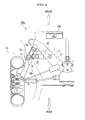
- FIG. 2 is a diagram of an electric power steering device in the steering system.
- FIG. 3 is a plain view of a toe angle changer on a left rear wheel side in the steering system.
- FIG. 4 is a schematic cross sectional view showing a structure of an actuator of a toe angle changer.
- FIG. 5 is a schematic diagram of a control function of a steering control ECU and toe angle changers in the steering system.
- FIGS. 6A and 6B are graphs showing properties of a base signal computing part and a damper compensation signal computing part, respectively.
- FIG. 7 is a block configuration diagram showing detailed functions of a self-aligning torque compensation computing part.
- FIG. 8 is a block configuration diagram showing a control function of a toe angle change control ECU of a toe angle changer.
- FIG. 9 shows a vehicle motion in accordance with a change in an operation angle, in a case of a vehicle to which the steering system of the present invention is applied: (a) shows a change over time of an operation angle of a steering wheel, (b) shows a change over time of a yaw rate ⁇ of the vehicle, (c) shows a change over time of a slip angle ⁇ of the vehicle, and (d) shows a change over time of a lateral acceleration G S .
- FIG. 10 shows a vehicle motion in accordance with a change in an operation angle, in a case of a vehicle having only a front wheel steering function: (a) shows a change over time of an operation angle of a steering wheel, (b) shows a change over time of a yaw rate ⁇ of the vehicle, (c) shows a change over time of a slip angle ⁇ of the vehicle, and (d) shows a change over time of a lateral acceleration G S .
- FIG. 11 shows a change over time of restoring moment of two front wheels around kingpin axis (steering axis), in accordance with a set input of the operation angle of the steering wheel shown in FIGS. 9 and 10 .
- FIG. 1 is a schematic diagram of an entire four-wheel vehicle having a steering system according to an embodiment of the present invention.
- FIG. 2 is a diagram of an electric power steering device.
- a steering system 100 includes an electric power steering device 110 having an electric motor 4 , which is configured to assist steering of front wheels 1 L, 1 R by a steering wheel 3 ; toe angle changers 120 L, 120 R configured to independently change toe angles of rear wheels 2 L, 2 R by respective actuators 30 , in accordance with a turning angle of the front wheels 1 L, 1 R by the electric power steering device 110 and a vehicle speed; a steering controller 130 (hereinbelow, referred to as “steering control ECU”) configured to control the electric power steering device 110 and the toe angle changers 120 L, 120 R; and various sensors, including a vehicle speed sensor S V , a yaw rate sensor S Y and a lateral acceleration sensor S GS .
- the electric power steering device 110 includes, as shown in FIG. 2 , the steering wheel 3 , a main steering shaft 3 a attached thereto, a shaft 3 c and a pinion shaft 7 , which shafts are connected through two universal joints 3 b .
- the pinion shaft 7 has a pinion gear 7 a provided on a lower end of the pinion shaft 7 , which engages with rack teeth 8 a of a rack shaft 8 which can reciprocate in a vehicle width direction.
- the left front wheel 1 L and the right front wheel 1 R are connected through tie rods 9 , 9 .
- the electric power steering device 110 can change traveling direction of the vehicle by the operation of the steering wheel 3 .
- the rack shaft 8 , the rack teeth 8 a and the tie rods 9 , 9 constitute a steering wheel turn mechanism.
- the pinion shaft 7 is supported by a steering gear box 6 : an upper portion, a middle portion and a lower portion of the pinion shaft 7 are supported through bearings 3 d , 3 e and 3 f , respectively.
- the electric power steering device 110 also has the electric motor 4 for supplying an auxiliary steering effort to reduce a steering effort required at the steering wheel 3 .
- the electric motor 4 has an output shaft with a worm gear 5 a which engages with a worm wheel gear 5 b provided on the pinion shaft 7 .
- the worm gear 5 a and the worm wheel gear 5 b constitute a deceleration mechanism.
- a rotor (not shown) of the electric motor 4 and the components connected to the electric motor 4 , such as the worm gear 5 a , the worm wheel gear 5 b , the pinion shaft 7 , the rack shaft 8 , the rack teeth 8 a and the tie rods 9 , 9 , constitute a steering unit.
- T M * T M ⁇ ( C m d ⁇ m /dt+J m d 2 ⁇ m /dt 2 ) i 2 (1)
- i represents a reduction gear ratio of the worm gear 5 a to the worm wheel gear 5 b
- ⁇ m represents the rotation angle of the electric motor
- J m and C m represent the inertia moment and the viscosity coefficient, respectively, of the rotor of the electric motor 4 .
- T M * and ⁇ m can be expressed with J m and C m of the rotor of the electric motor 4 , which means the relationship is independent of the vehicle properties or the vehicle state.
- a steering torque applied to the steering wheel 3 is represented as T S
- the steering torque T s can be represented by the following formula (3).
- T S T P /(1+ k A ( VS )) (3)
- the electric power steering device 110 also includes an electric motor drive circuit 23 configured to drive the electric motor 4 ; a resolver 25 ; a torque sensor S T configured to detect (measure) a pinion torque T P applied to the pinion shaft 7 ; a differential amplifier 21 configured to amplify the output from the torque sensor S T ; and the vehicle speed sensor S V configured to detect (measure) a vehicle speed.
- an electric motor drive circuit 23 configured to drive the electric motor 4 ; a resolver 25 ; a torque sensor S T configured to detect (measure) a pinion torque T P applied to the pinion shaft 7 ; a differential amplifier 21 configured to amplify the output from the torque sensor S T ; and the vehicle speed sensor S V configured to detect (measure) a vehicle speed.
- the electric motor steering control ECU 130 of the steering system 100 has an electric power steering control part 130 a (which will be described below; see FIG. 5 ) as a functional part of the electric power steering device 110 , which controls the driving of the electric motor 4 .
- the electric motor drive circuit 23 has switching elements, such as three-phase FET bridge circuit, and is configured to generate a square-wave voltage based on duty signals (DU, DV, DW) from the electric power steering control part 130 a (see FIG. 5 ), to thereby drive the electric motor 4 .
- switching elements such as three-phase FET bridge circuit
- the electric motor drive circuit 23 also has a function to detect (measure) a three-phase electric motor current I (IU, IV, IW) using a Hall element (not shown).
- the resolver 25 is configured to detect (measure) a rotation angle ⁇ m of the electric motor 4 and to output an angular signal ⁇ , and examples include a sensor for detecting a change in magnetoresistance which is positioned in the vicinity of a magnetic rotor having a plurality of recess portions and projection portions arranged evenly along a circumference of the rotor.
- the torque sensor S T is configured to detect (measure) the pinion torque T P applied to the pinion shaft 7 .
- the torque sensor S T is formed of magnetostrictive films adhered to the pinion shaft 7 at two different positions along an axis thereof so as to exhibit opposite anisotropies, and detection coils are arranged with a gap from the pinion shaft 7 along the surface (outer circumference) of the respective magnetostrictive films.
- the differential amplifier 21 is configured to amplify a difference in permeability change between two magnetostrictive films detected as an inductance change by the detection coil, and to output a torque signal T.
- the vehicle speed sensor S V is configured to detect (measure) the vehicle speed VS as a pulse number per unit time, and to output a vehicle speed signal VS.
- the functional configuration of the steering control ECU 130 will be described later, together with the control by the electric power steering device 110 and the control by the toe angle changers 120 L, 120 R.
- FIG. 3 is a plain view of a toe angle changer on a left rear wheel side.
- FIG. 4 is a schematic cross sectional view showing a structure of an actuator of a toe angle changer.
- the toe angle changers 120 L, 120 R are installed to the left rear wheel 2 L and the right rear wheel 2 R of the vehicle, respectively.
- the toe angle changer 120 L is taken as an example, and the left rear wheel 2 L is shown in FIG. 3 .
- the toe angle changer 120 L includes the actuator 30 and a toe angle change controller (hereinbelow, referred to as “toe angle change control ECU”) 37 .
- FIG. 3 shows the left rear wheel 2 L only, but the components are arranged in the same manner (symmetrically) on the right rear wheel 2 R. It is also noted that the steering control ECU 130 and the toe angle change control ECUs 37 , 37 constitute the steering controller of the present invention.
- the cross member 12 extends substantially in the vehicle width direction, and end portions (in terms of the vehicle width direction) thereof are elastically supported by a rear side frame 11 of the vehicle body.
- a trailing arm 13 extends substantially in the front-rear direction of the vehicle body, and a front end portion thereof is supported by a portion near the terminal (in terms of the vehicle width direction) of the cross member 12 .
- the rear wheel 2 L is fixed to a rear end portion of the trailing arm 13 .
- the trailing arm 13 is formed of a vehicle body-side arm 13 a attached to the cross member 12 , and a wheel-side arm 13 b fixed to the rear wheel 2 L, which are connected to each other through a nearly vertical rotation axis 13 c . With this configuration, the trailing arm 13 is displaceable in the vehicle width direction.
- one end portion is attached through a ball joint 16 to a front end portion of the wheel-side arm 13 b relative to the rotation axis 13 c , and the other end (base end) portion of the actuator 30 is fixed to the cross member 12 through a ball joint 17 .
- the actuator 30 includes an electric motor 31 , a deceleration mechanism 33 , a feed screw portion 35 and the like.
- the electric motor 31 may be a brush motor, a brushless motor or the like, which can rotate in both forward and reverse directions.
- the electric motor 31 has a temperature sensor 31 a configured to detect (measure) a winding temperature of a coil of the electric motor 31 , and to input a detected temperature signal to a self-diagnostic part 81 d (see FIG. 8 ), which will be described below, of the toe angle change control ECU 37 .
- the deceleration mechanism 33 is formed of, for example, double planetary gears (not shown) or the like assembled therein.
- the self-diagnostic part 81 d and the temperature sensor 31 a constitute an anomaly detection unit of the present invention.
- the feed screw portion 35 includes: a rod 35 a in a shape of a cylinder; a nut 35 c in a shape of a cylinder which has an internal thread 35 b formed in an inner periphery thereof and is inserted in the rod 35 a ; and a screw shaft 35 d which engages with the internal thread 35 b and supports the rod 35 a in such a manner that the rod 35 a is movable in an axial direction.
- the feed screw portion 35 , the deceleration mechanism 33 and the electric motor 31 are encased in a case body 34 in an elongated cylinder shape.
- a boot 36 is attached so as to cover both an end portion of the case body 34 and an end portion of the rod 35 a , in order to prevent dust or foreign matter from attaching to an outer periphery of the rod 35 a exposed from the end portion of the case body 34 , and to prevent dust, foreign matter or water from entering the case body 34 .
- One end portion of the deceleration mechanism 33 is connected to an output shaft of the electric motor 31 , and the other end portion is connected to the screw shaft 35 d .
- the rod 35 a shifts in a right-left direction in the drawing (axial direction) relative to the case body 34 , and thus the actuator 30 contracts or expands. Due to the frictional force caused by engagement of the screw shaft 35 d and the internal thread 35 b of the nut 35 c , a toe angle of the rear wheel is maintained constant, even when the electric motor 31 is not energized and driven.
- the actuator 30 also includes a stroke sensor 38 configured to detect (measure) the position of the rod 35 a (i.e., amount of expansion/contraction).
- a magnet or the like is embedded so as to detect (measure) the location of the rod 35 a by utilizing magnetism. In this manner, by detecting the position of the rod 35 a using the stroke sensor 38 , the steering angles (toe angle) of toe-in or toe-out of the rear wheels 2 L, 2 R are separately detected with high accuracy.
- the ball joint 16 provided on an end portion of the rod 35 a is rotatably connected to the wheel-side arm 13 b of the trailing arm 13 (see FIG. 3 ), and the ball joint 17 provided on the base end of the case body 34 (right-hand end in FIG. 4 ) is rotatably connected to the cross member 12 (see FIG. 3 ).
- the power of the electric motor 31 rotates the screw shaft 35 d and the rod 35 a shifts leftward (in FIG. 4 ) (i.e., the actuator 30 expands)
- the wheel-side arm 13 b is pushed outward in the vehicle width direction (left direction in FIG. 3 ) to thereby leftward turn the rear wheel 2 L.
- the position to which the ball joint 16 of the actuator 30 is attached is not limited to the wheel-side arm 13 b and the actuator 30 can be attached to any position, such as on a knuckle arm, as long as the toe angle of the rear wheel 2 L can be changed.
- the toe angle changers 120 L, 120 R are applied to an independent suspension system with semi-trailing arms.
- the present invention is not limited to this type of suspension system, and may be applied to other types of suspension system.
- the actuator 30 may be introduced to a side rod of a double wishbone type suspension, or a side rod of a strut type suspension.
- the toe angle change control ECU 37 is unified with the actuator 30 .
- the toe angle change control ECU 37 is fixed to the case body 34 of the actuator 30 , and connected to the stroke sensor 38 and the temperature sensor 31 a through connectors or the like. Between two toe angle change control ECUs 37 , 37 , and between the toe angle change control ECU 37 and the steering control ECU 130 , there are provided signal circuits connecting them to each other.
- toe angle change control ECU 37 power is supplied from a power source (not shown), such as a battery, mounted on a vehicle. Also to the steering control ECU 130 and the electric motor drive circuit 23 , power is supplied from a power source (not shown), such as battery, which is an independent system of that of the toe angle change control ECU 37 .
- FIG. 5 is a schematic diagram of a control function of a steering control ECU and toe angle changers in the steering system.
- FIGS. 6A and 6B are graphs showing properties of a base signal computing part and a damper compensation signal computing part, respectively.
- the steering control ECU 130 includes a microcomputer with components, such as CPU, ROM, RAM (not shown), and a peripheral circuit and the like.
- the steering control ECU 130 includes: the electric power steering control part 130 a configured to control the electric power steering device 110 (see FIGS. 1 and 2 ); and a rear wheel toe angle control part 130 b , which is a feature of the present invention, configured to compute target toe angles of the rear wheel 2 L, 2 R and to compute a compensation value for a difference in the self-aligning torque (which will be described below) to be output to the electric power steering control part 130 a.
- the electric power steering control part 130 a includes: a base signal computing part (auxiliary torque calculating unit) 51 ; a damper compensation signal computing part (auxiliary torque calculating unit) 52 ; an inertia compensation signal computing part (auxiliary torque calculating unit) 53 ; a Q-axis (torque axis) PI control part 54 ; a D-axis (axis of magnetic pole) PI control part 55 ; a 2-axis-to-3-phase conversion part 56 ; a PWM conversion part 57 ; a 3-phase-to-2-axis conversion part 58 ; an electric motor speed calculating part 67 ; and an exciting current generation part 59 .
- the 3-phase-to-2-axis conversion part 58 converts a three-phase current IU, IV, IW of the electric motor 4 detected by the electric motor drive circuit 23 into a two-axis current, including a D-axis which is an axis of magnetic pole of the rotor of the electric motor 4 , and a Q-axis which is obtained by electrically rotating the D-axis by 90 degrees.
- a Q-axis current IQ is proportional to the torque T M generated at the electric motor 4
- a D-axis current ID is proportional to an exciting current.
- the electric motor speed calculating part 67 introduces a differential operator to an angular signal ⁇ of the electric motor 4 , to thereby generate an angular velocity signal ⁇ .
- the exciting current generation part 59 generates a target signal for the exciting current of the electric motor 4 , and if desired, field-weakening control can be performed by making the D-axis current substantially equal to the Q-axis current.
- the base signal computing part 51 Based on the torque signal T and the vehicle speed signal VS, the base signal computing part 51 generates a base signal (target value) D T to be used as a standard reference for a target signal IM 1 of the output torque T M *.
- the signal is generated from a base table (first table) 51 a with reference to the torque signal T and the vehicle speed signal VS, which table had been prepared by experimental measurement or the like using a vehicle which is the same model as that of the present embodiment but has only a front wheel steering function.
- FIG. 6A is a graph showing a function of the base signal D T , stored in the base table 51 a .
- a dead zone N 1 is provided where the base signal D T is set to zero when the value of the torque signal T is small, and the base signal D T linearly increases along a gain G 1 when the value of the torque signal T is larger than the value in the dead zone N 1 .
- the base signal computing part 51 increases the output along a gain G 2 at specific torque values, and when the torque value further increases, the output is made saturated.
- a vehicle body in general has various road loads (road reactions) depending on the running speed thereof. Accordingly, the gain is adjusted based on the vehicle speed signal VS.
- a steady responsive feeling is provided from the steering torque T S . In this case, it is necessary that the inertia compensation be made also in the manual steering zone.
- the base signal computing part 51 stores a backup table (second table) 51 b , and in response to a command from a toe angle change control diagnostic part 73 , which will be described below, generates the base signal D T to be used as a standard reference for the target signal IM 1 of the output torque T M *, from the backup table 51 b with reference to the torque signal T and the vehicle speed signal VS, when the toe angle changers 120 L, 120 R are in an abnormal state.
- a backup table second table
- the backup table 51 b has a function of the torque signal T and the vehicle speed signal VS as also shown in FIG. 6A , but the values of the gains (G 1 , G 2 ) are smaller by notable amounts than those in the case of the base table 51 a , for the same vehicle speed. With this setting, the auxiliary torque becomes smaller, making it easier for the driver to sense an abnormal state.
- the damper compensation signal computing part 52 is introduced for compensating a viscosity in the steering unit, and for providing a steering damper function for compensating convergence when convergence decreases during high-speed driving, by reading a damper table 52 a with reference to the angular velocity signal ⁇ .
- FIG. 6B is a graph showing a characteristic function of the damper table 52 a , in which the line is formed of a several linear sections and a compensation value I as a whole increases as the angular velocity ⁇ of the electric motor 4 increases.
- the graph is also characterized in that the compensation value I rapidly increases when the angular velocity ⁇ is in a specific range.
- the angular velocity of the electric motor 4 i.e. the output torque T M * of the electric motor 4 in accordance with the speed of the steering wheel turn, decreases by increasing the gain.
- the damper compensation signal computing part 52 makes the current supply to the electric motor 4 larger, to thereby perform an inhibitory control of the angular velocity ⁇ when the steering wheel 3 is resuming the home position. Because of this steering damper effect, convergence of the steering wheel 3 is improved, to thereby stabilize the vehicle properties.
- an adder 61 is configured to subtract the output signal I of the damper compensation signal computing part 52 from the output signal D T of the base signal computing part 51
- an adder 62 is configured to add the output signal from the adder 61 and the output from the inertia compensation signal computing part 53 and to output the output signal IM 1 .
- an assist control is performed by a combination of the base signal computing part 51 , the damper compensation signal computing part 52 and the adder 61 .
- the inertia compensation signal computing part 53 is configured to compensate an effect caused by the inertia in the steering unit, in which the torque signal T is computed from an inertia table 53 a.
- the inertia compensation signal computing part 53 compensates the lowering of the response caused by the inertia of the rotor of the electric motor 4 .
- the inertia compensation signal computing part 53 controls the timing of switching the rotation direction of the electric motor 4 , so as to synchronize the timing of switching the rotation direction of the electric motor 4 with that of the steering wheel 3 .
- the inertia compensation signal computing part 53 reduces a response lag in the steering, which may otherwise be caused by inertia, viscosity or the like in the steering unit, to thereby give an excellent steering feeling.
- the inertia compensation signal computing part 53 can practically impart the above-mentioned features to various steering properties which varies depending on vehicle characteristics, such as those specifically different among FF (Front engine Front wheel drive) vehicle, FR (Front engine Rear wheel drive) vehicle, RV (Recreation Vehicle) and sedan (or saloon) car, and vehicle states, such as vehicle speed, as well as road conditions.
- vehicle characteristics such as those specifically different among FF (Front engine Front wheel drive) vehicle, FR (Front engine Rear wheel drive) vehicle, RV (Recreation Vehicle) and sedan (or saloon) car
- vehicle states such as vehicle speed, as well as road conditions.
- the output signal IM 1 of the adder 62 is a target signal for the Q-axis current which defines the torque of the electric motor 4 .
- An adder (difference compensation unit) 63 is configured to subtract, from the output signal IM 1 , a compensation value for the difference in the self-aligning torque which is output from a self-aligning torque compensation computing part 72 , details of which will be described later, and to send an output signal IM 2 to an adder 64 .
- the adder 64 is configured to subtract the Q-axis current IQ from the output signal IM 2 , and to generate a deviation signal IE.
- the Q-axis (torque axis) PI control part 54 is configured to perform a P (proportional) control and an I (integral) control so as to reduce the deviation signal IE.
- An adder 65 is configured to subtract the D-axis current ID from the output signal of the exciting current generation part 59 .
- the D-axis (axis of magnetic pole) PI control part 55 is configured to perform a PI feedback control so as to reduce the output signal from the adder 65 .
- the 2-axis-to-3-phase conversion part 56 is configured to convert two-axis signal including an output signal VQ from the Q-axis (torque axis) PI control part 54 and an output signal VD from the D-axis (axis of magnetic pole) PI control part 55 into three-phase signal UU, UV, UW.
- the PWM conversion part 57 is configured to generate duty signals (DU, DV, DW), which is a ON/OFF signal [PWM (Pulse Width Modulation) signal] having pulse widths proportional to the magnitude of the three-phase signal UU, UV, UW.
- the angular signal ⁇ of the electric motor 4 is input to the 2-axis-to-3-phase conversion part 56 and the PWM conversion part 57 , and a signal corresponding to the magnetic pole position of the rotor is output.
- the rear wheel toe angle control part 130 b includes a front wheel turning angle computing part 68 , a target toe angle computing part 71 , the self-aligning torque compensation computing part 72 and the toe angle change control diagnostic part 73 .
- the front wheel turning angle computing part 68 is configured to calculate a turning angle ⁇ of the front wheels 1 L, 1 R based on the angular signal ⁇ output from the resolver 25 , and to input the result to the target toe angle computing part 71 and the self-aligning torque compensation computing part 72 .
- the target toe angle computing part 71 is configured to generate target toe angles ⁇ TL , ⁇ TR for respective rear wheels 2 L, 2 R, based on the vehicle speed signal VS, a turning angle ⁇ , and a turning angular velocity which is obtained by differentiation of the turning angle ⁇ (this can be easily obtained since the turning angle ⁇ is proportional to the angular velocity ⁇ of the electric motor 4 ), and to input the target toe angles ⁇ TL , ⁇ TR to the respective toe angle change control ECUs 37 , 37 configured to control respective toe angle changes of the left rear wheel 2 L and the right rear wheel 2 R (see FIG. 8 ).
- the target toe angles ⁇ TL , ⁇ TR are generated from the toe angle table 71 a , with reference to the turning angle ⁇ , the angular velocity ⁇ ′ of the turning angle ⁇ and the vehicle speed VS, which table had been prepared for each of the left rear wheel 2 L and the right rear wheel 2 R in advance.
- ⁇ TL K L ( VS , ⁇ ′, ⁇ ) ⁇ (4)
- ⁇ TR K R ( VS , ⁇ ′, ⁇ ) ⁇ (5)
- each of K L (VS), K R (VS) represents a front-rear wheel steering ratio which depends on the vehicle speed VS, the turning angle ⁇ and the angular velocity ⁇ ′ of the turning angle.
- each of the target toe angles or ⁇ TL , ⁇ TR of the rear wheel is generated in such a manner that the rear wheels 2 L, 2 R are in antiphase relative to the front wheels, in accordance with the turning angle ⁇ , to allow the vehicle to turn in a small radius.
- the target toe angles or ⁇ TL , ⁇ TR of the rear wheels 2 L, 2 R are set as the same phase relative to the front wheels, in accordance with the turning angle ⁇ .
- the target toe angles or ⁇ TL , ⁇ TR of the rear wheels 2 L, 2 R are set so as to make the slip angle ⁇ small during lane change.
- the target toe angles or ⁇ TL , ⁇ TR of the rear wheels are set to the antiphase relative to the front wheels, in accordance with the turning angle ⁇ .
- each of the target toe angles or ⁇ TL , ⁇ TR generated in the target toe angle computing part 71 do not necessarily follow Ackerman-Jeantaud geometry.
- each of the target toe angles or ⁇ TL , ⁇ TR may be, for example, 2°, with the wheels toed in.
- the self-aligning torque compensation computing part 72 has a motion parameter calculating part (restoring torque calculating unit or reference restoring torque calculating unit) 72 a , a self-aligning torque calculating part (restoring torque calculating unit) 72 b , a reference self-aligning torque calculating part (reference restoring torque calculating unit) 72 c , and a self-aligning torque difference calculating part (difference compensation unit) 72 d.
- the motion parameter calculating part 72 a is configured to calculate a slip angle ⁇ of the vehicle body, based on the yaw rate ⁇ from the yaw rate sensor S Y (see FIG. 1 ), the vehicle speed VS, the lateral acceleration G S from the lateral acceleration sensor S GS , the turning angle ⁇ , and the target toe angles ⁇ TL , ⁇ TR of the rear wheels 2 L, 2 R.
- the slip angle ⁇ is obtained from the slip angle table (not shown), with reference to the yaw rate ⁇ , the vehicle speed VS, the lateral acceleration G S , the turning angle ⁇ and the target toe angles or ⁇ TL , ⁇ TR of the rear wheels 2 L, 2 R, which table had been prepared by experimental measurement or the like in advance.
- the motion parameter calculating part 72 a also has a reference yaw rate conversion table, a reference slip angle conversion table and a reference lateral acceleration conversion table (all are not shown).
- a reference yaw rate ⁇ * corresponding to the present turning angle ⁇ of the front wheels 1 L, 1 R and the vehicle speed VS of the vehicle having only a front steering wheel turn function is obtained from the reference yaw rate conversion table with reference to the vehicle speed VS and the turning angle ⁇ ;
- a reference lateral acceleration G* S corresponding to the present turning angle ⁇ of the front wheels 1 L, 1 R and the vehicle speed VS of the vehicle having only a front steering wheel turn function is obtained from the reference lateral acceleration conversion table;
- a reference slip angle ⁇ * of the vehicle having only a front steering wheel turn function is calculated from the reference slip angle conversion table with reference to the reference yaw rate ⁇ *, the vehicle speed VS, the reference lateral acceleration G* S and the turning angle ⁇ .
- the calculated slip angle ⁇ is input to the self-aligning torque calculating part 72 b , and the calculated reference yaw rate ⁇ * and the reference slip angle ⁇ * are input to the reference self-aligning torque calculating part 72 c.
- the self-aligning torque calculating part 72 b calculates the restoring moment T S, RTC generated around the kingpin axis (or steering axis, not shown) of the front wheels 1 L, 1 R using, for example, the following formula (6), and further converts the calculated value into the self-aligning torque T SAT, RTC in terms of the torque around the shaft 3 c of the steering wheel 3 (see FIG. 2 ), as represented by the following formula (7):
- ⁇ ⁇ c+ ⁇ n with the proviso that a caster trail is represented as ⁇ c and a pneumatic trail is represented as ⁇ n
- l f represents a distance between the front wheel axle and a center of gravity
- K f represents a cornering stiffness of the front wheel tire
- C represents a coefficient that converts a moment around the kingpin axis (steering axis) into a torque around the shaft 3 c of the steering wheel 3 .
- the reference self-aligning torque calculating part 72 c calculates the reference restoring moment T S * generated around the kingpin axis (or steering axis, not shown) of the front wheels 1 L, 1 R in the case of a reference yaw rate ⁇ *, the present turning angle ⁇ and the reference slip angle ⁇ * of a hypothetical vehicle having only a front wheel steering function, using, for example, the following formula (8), and further converts the calculated value into the reference self-aligning torque T* SAT in terms of the torque around the shaft 3 c of the steering wheel 3 (see FIG. 2 ), as represented by the following formula (9):
- T S * 2 ⁇ ⁇ ⁇ ⁇ K f ⁇ ( ⁇ * + l f VS ⁇ ⁇ * - ⁇ ) ( 8 )
- T SAT * C ⁇ T S * ( 9 )
- the self-aligning torque difference calculating part 72 d calculates the compensation value for the difference between the reference self-aligning torque T* SAT and the self-aligning torque in terms of the torque around the shaft 3 c (see FIG. 2 ) T SAT, RTC , calculated above with the formulae (7) and (9), by the following formula (10): ( T* SAT ⁇ T SAT,RTC ) ⁇ k (10)
- k represents a coefficient and a tuning parameter.
- the compensation value for the difference between the self-aligning torques, calculated by the formula (10), is input to the adder 63 .
- the coefficient C may be a specific constant value, or a specific variable which changes depending on the vehicle speed VS or the like.
- the coefficient C is changed in accordance with the torque signal T and the vehicle speed VS (i.e., the gain), since the same gain is used for the compensation of the self-aligning torque and that of the auxiliary torque.
- the compensation can be made for the difference between the self-aligning torque T SAT,RTC of the all-wheel steering vehicle and the self-aligning torque T* SAT of the vehicle having a steering function of only front wheels 1 L, 1 R, in the adder 63 of the electric power steering control part 130 a . Therefore, even when a driver who is used to a conventional vehicle having only a front wheel steering function drives an all-wheel steering vehicle, the driver does not feel discomfort in the responsive feeling from the steering torque of the steering wheel 3 .
- the toe angle change control diagnostic part 73 is configured, when receives an anomaly detection signal from the self-diagnostic part 81 d (which will be described below, see FIG. 8 ) of the toe angle change control ECU 37 in the toe angle changer 120 L, 120 R, to command the self-aligning torque compensation computing part 72 not to compute a compensation but to output a zero signal, and to output a command to the base signal computing part 51 to switch the reference from the base table 51 a to the backup table 51 b.
- the self-diagnostic part 81 d which will be described below, see FIG. 8
- FIG. 8 is a block configuration diagram showing a control function of a toe angle change control ECU of a toe angle changer.
- the toe angle change control ECU 37 has a function to drive control the actuator 30 , and is formed of a control part 81 and an electric motor drive circuit 83 .
- Each toe angle change control ECU 37 is connected to the steering control ECU 130 through a communication line, and also to the other toe angle change control ECU 37 through a communication line.
- the control part 81 includes a microcomputer with components, such as CPU, RAM, ROM, and a peripheral circuit, and has a target current calculating part 81 a , a motor control signal generation part 81 c and the self-diagnostic part (anomaly detection unit) 81 d.
- the target current calculating part 81 a of one toe angle change control ECU 37 (on aright rear wheel 2 R side) is configured to calculate a target current signal based on the target toe angle ⁇ TR of the rear wheel 2 R input through the communication line from the steering control ECU 130 and on the present toe angle ⁇ R of the rear wheel 2 R obtained from the stroke sensor 38 , and to output the result to the motor control signal generation part 81 c.
- the target current calculating part 81 a of the other toe angle change control ECU 37 (on a left rear wheel 2 L side) is configured to calculate a target current signal based on the target toe angle ⁇ TL of the rear wheel 2 L input through the communication line from the steering control ECU 130 and on the present toe angle ⁇ L of the rear wheel 2 L obtained from the stroke sensor 38 , and to output the result to the motor control signal generation part 81 c.
- the target current signal is a current signal required for setting the actuator 30 so as to realize a desired operation amount of the actuator 30 (amount of expansion/contraction of the actuator 30 that allows the rear wheel 2 L (or 2 R) to have a desired toe angle ⁇ TL (or ⁇ TR )) at a desired speed.
- the target toe angle ⁇ TL (or ⁇ TR ) is set promptly in the target current calculating part 81 a , by feeding the present toe angle ⁇ L (or ⁇ R ) and the target toe angle ⁇ TL (or ⁇ TR ) and correcting the target current signal, and by feeding a change in the current value required for the steering wheel turn of the rear wheel 2 L (or 2 R) which change is caused by the vehicle speed VS, road conditions, motional states of the vehicle, wear status of tire, or the like.
- the motor control signal generation part 81 c is configured to receive the target current signal from the target current calculating part 81 a , and to output the motor control signal to the electric motor drive circuit 83 .
- the motor control signal includes a value of the current to be supplied to the electric motor 31 , and a direction of the current.
- the electric motor drive circuit 83 is formed of, for example, a bridge circuit with FET (Field Effect Transistor), and configured to supply an electric motor current to the electric motor 31 , based on the motor control signal.
- the self-diagnostic part 81 d is configured to determine whether or not an abnormal state is detected, based on a position signal of the stroke sensor 38 of the toe angle changer 120 L or the toe angle changer 120 R (to which the self-diagnostic part 81 d of interest belongs), a detection signal from a Hall element of the electric motor drive circuit 83 , a temperature signal from the temperature sensor 31 a , and a state monitoring of the target current calculating part 81 a.
- the self-diagnostic part 81 d determines that a winding temperature of the electric motor 31 is abnormal when the signal from the temperature sensor 31 a exceeds a specific value, and inputs a specific target toe angle ⁇ SL (or ⁇ SR ), such as 0°, to the target current calculating part 81 a .
- a specific target toe angle ⁇ SL or ⁇ SR , such as 0°
- the target toe angles ⁇ SL and ⁇ SR are target toe angles regarding the left rear wheel 2 L and the right rear wheel 2 R, respectively, when anomaly is detected.
- the self-diagnostic part 81 d is configured to monitor the detection signals from the target current calculating part 81 a and a Hall element of the electric motor drive circuit 83 , and to determine whether or not the actuator 30 is locked, based on the position signal from the stroke sensor 38 : when it is determined that the actuator 30 is locked, the self-diagnostic part 81 d commands the electric motor drive circuit 83 to stop the power supply to the electric motor 31 , and inputs the present toe angle ⁇ L (or ⁇ R ) as the target toe angle ⁇ SL (or ⁇ SR ) to the target current calculating part 81 a , and then sends an anomaly detection signal and a signal of a mode indicating that a process is made in response to the anomaly detection, to the self-diagnostic part 81 d of the other toe angle change control ECU 37 .
- a watch dog circuit may be provided as a peripheral circuit in addition to the self-diagnostic part 81 d , to monitor the control part 81 .
- the electric motor drive circuit 83 may be commanded to stop a power supply to the electric motor 31 , and then an anomaly detection signal may be output to the self-diagnostic part 81 d of the other toe angle change control ECU 37 .
- the self-diagnostic part 81 d of the toe angle changer 120 L (or 120 R) is configured to check whether or not there is an anomaly detection signal from the self-diagnostic part 81 d of the toe angle change control ECU 37 of the other toe angle changer 120 R (or 120 L).
- the target toe angle ⁇ SL (or ⁇ SR ) is input to the target current calculating part 81 a , based on the signal of a mode indicating that a process is made.
- the self-diagnostic part 81 d monitors a signal indicating whether or not the toe angle changer 120 L (or 120 R) corresponding to the toe angle change control ECU 37 of interest is normally operated, and at the same time, monitors a signal indicating whether or not the toe angle changer 120 R (or 120 L) corresponding to the other toe angle change control ECU 37 is normally operated.
- both of the toe angle change control ECUs 37 , 37 perform a process in the same specific mode.
- the self-diagnostic part 81 d sends the anomaly detection signal to the toe angle change control diagnostic part 73 .
- the driver can be provided with a responsive feeling from the steering torque very similar to that in a vehicle having only a
- the base table 51 a to be referred to in the base signal computing part 51 may be not be formed separately for the vehicle to which the steering system 100 is applied and for the vehicle having only a front wheel steering function, and the same base table 51 a for the conventional vehicle having only a front wheel steering function may be used. In this case, the preparation of the control data in the base table 51 a for the vehicle to which the steering system 100 is applied can be omitted.
- FIGS. 9-11 show changes over time of the yaw rate ⁇ , the slip angle ⁇ , the lateral acceleration G S and the moment around the kingpin axis (steering axis), with reference to the change in operation angle ⁇ H of the steering wheel 3 , for both the vehicle to which the steering system 100 is applied and the vehicle having only a front wheel steering function, in the case where the operation angle ⁇ H of the steering wheel 3 is operated up to 100° (deg) at the vehicle speed of 80 km/h.
- FIG. 9 shows graphs for a vehicle to which the steering system 100 is applied: (a) shows a change over time of an operation angle ⁇ H (deg) of a steering wheel, (b) shows a change over time of a yaw rate ⁇ (deg/s) of the vehicle, (c) shows a change over time of a slip angle ⁇ (deg) of the vehicle, and (d) shows a change over time of a lateral acceleration G S (G).
- FIG. 10 shows graphs for a vehicle having only a front wheel steering function: (a) shows a change over time of an operation angle ⁇ H (deg) of a steering wheel, (b) shows a change over time of a yaw rate ⁇ (deg/s) of the vehicle, (c) shows a change over time of a slip angle ⁇ (deg) of the vehicle, and (d) shows a change over time of a lateral acceleration G S (G).
- FIG. 11 shows a change over time of resorting moment of two front wheels around kingpin axis (steering axis), in accordance with a step input of the operation angle of the steering wheel ⁇ H of the steering wheel 3 shown in FIGS. 9 and 10 , with a comparison being made between the vehicle to which the steering system 100 is applied and a vehicle having only a front wheel steering function.
- the toe angles of the rear wheels 2 L, 2 R are set to antiphase relative to the turning angle ⁇ of the front wheels 1 L, 1 R, and thus the vehicle can turn in a small radius, with a larger yaw rate ⁇ , slip angle ⁇ and lateral acceleration G S , as compared with those in the vehicle having only a front steering wheel turn function.
- the restoring moment around the kingpin axis (steering axis) becomes larger in the vehicle to which the steering system 100 is applied (curve a in FIG. 11 ) than in the vehicle having only a front wheel steering function (curve b).
- the self-aligning torque compensation computing part 72 calculates a compensation value corresponding to the difference in the restoring moment between the curve a and the curve b and the adder 63 makes subtraction based on the compensation value.
- the steering control ECU 130 switches the table to be used in the base signal computing part 51 from the base table 51 a to the backup table 51 b , and sets the output signal from the self-aligning torque compensation computing part 72 to the adder 63 to a zero signal.
- the auxiliary torque becomes smaller and the responsive feeling from the steering torque given to the driver becomes large, making it easier for the driver to sense an abnormal state of the steering function.
- the self-diagnostic part 81 d of one of the toe angle change control ECUs 37 , 37 detects an abnormal state
- the self-diagnostic part 81 d sends an anomaly detection signal to the other toe angle change control ECU 37 , and both of the toe angle changers 120 L, 120 R are controlled so that the toe angles are fixed. Therefore, it is prevented that a change of only one of the toe angles between the rear wheels 2 L, 2 R remains controlled, and thus a driving performance is maintained stable even when the toe angle changers 120 L, 120 R are in an abnormal state.
- the self-diagnostic part 81 d inputs a specific value (such as 0° or 0.5° toe-in) as the target toe angles ⁇ SL , ⁇ SR for an abnormal state to the target current calculating part 81 a where the target toe angles or ⁇ TL , ⁇ TR are set
- the vehicle is limited to have only a front wheel steering function like a conventional vehicle, and based on the command from the toe angle change diagnostic part 73 , the self-aligning torque compensation computing part 72 outputs a zero signal as the compensation signal to the adder 63 .
- the base signal (target value) D T output from the base signal computing part 51 in accordance with the command from the toe angle change diagnostic part 73 gives a larger responsive feeling from the steering torque by referring to the backup table 51 a . Since the target signal of the auxiliary torque corresponding to the vehicle having only a front wheel steering function is output, the steering properties coordinate with the vehicle properties, leading to the prevention of a sudden shift in the change of the steering feeling that the driver feels.
- the toe angle change control ECU 37 calculates the target current and is unified with the actuator 30 and thus separately arranged from the steering control ECU 130 .
- the detected value (position information) by the stroke sensor 38 does not have to be sent to the steering control ECU 130 , and it becomes possible to feed-back-wise process the position control and current control in the toe angle change control ECU 37 .
- an independent feedback loop is formed in the toe angle changer 120 L (or 120 R), and thus it becomes possible that settings can be made in accordance with the individual actuator 30 in a different state from that of the other actuator 30 (i.e., it is not necessary to make settings in accordance with the steering control ECU 130 ), leading to increase in the processing speed.
- the steering control ECU 130 does not output a command including the actuation amount to the toe angle change control ECU 37 ; instead, the steering control ECU 130 outputs only a signal of the target toe angle ⁇ SL , ⁇ SR , resulting in a minimum load on the steering control ECU 130 .
- the control part 81 itself of the toe angle change control ECU 37 is configured to calculate the target current, making the feedback loop shortest, thus improving the control accuracy.
- the responsive feeling from the steering torque by the electric power steering device of the front wheel in the all-wheel steering vehicle is made nearly equivalent to the responsive feeling from the steering torque by the electric power steering device of the front wheel in the vehicle having only a front wheel steering, and the driver who is used to the vehicle having an electric power steering device only for front wheel does not feel discomfort.
- the steering system allows the driver to easily recognize the abnormal state of the toe angle changer by the change in the responsive feeling from the steering torque, when the toe angle changer is in an abnormal state, for example, the toe angle of the rear wheel is locked.
- the front wheel turning angle computing part 68 makes calculation based on the angular signal ⁇ of the electric motor 4 .
- a turning angle sensor may be provided in the steering wheel turn mechanism to directly detect (measure) the turning angle ⁇ .
- an operation angle sensor may be provided on the pinion shaft 7 and the turning angle ⁇ may be computed from an operation angle signal of the steering wheel 3 .
- the self-aligning torque calculating part 72 b and the reference self-aligning torque calculating part 72 c the self-aligning torque and the reference self-aligning torque around the shaft 3 c are calculated using the formulae (6)-(9).
- the torques can be calculated in different manners.
- a calculation model including the vehicle speed VS, turning angle ⁇ , yaw rate ⁇ and lateral acceleration G S as input parameters may be prepared from actual measurements using an actual vehicle in advance, and the self-aligning torque and the reference self-aligning torque may be calculated using the calculation model.
- This calculation model may be a nonlinear model, such as a neural network, or may be a linear model, such as a transfer function.
- the degree of change in the gain when switching from the base table 51 a to the backup table 51 b may not be fixed, and based on the difference between the value of the target toe angle ⁇ S ( ⁇ SL , ⁇ SR ) for the rear wheel in an abnormal state and the reference value (such as toe-in value of 0° or 0.5°), the assist amount may be made smaller (i.e., the gains G 1 , G 2 may be made smaller) when the difference is larger.
- the current in the electric motor 4 is controlled by setting the target current.
- a target voltage may be set as a voltage to be applied to the electric motor 4 .
- a target torque may be set as a torque to be output by the electric motor 4 , to thereby control the current in the electric motor 4 .
- Such a target voltage and a target torque are included in the target signal.
Landscapes
- Engineering & Computer Science (AREA)
- Chemical & Material Sciences (AREA)
- Combustion & Propulsion (AREA)
- Transportation (AREA)
- Mechanical Engineering (AREA)
- Power Steering Mechanism (AREA)
- Steering Control In Accordance With Driving Conditions (AREA)
- Steering-Linkage Mechanisms And Four-Wheel Steering (AREA)
Abstract
Description
T M *=T M−(C m dθ m /dt+J m d 2θm /dt 2)i 2 (1)
T S =T P/(1+k A(VS)) (3)
αTL =K L(VS,δ′,δ)·δ (4)
αTR =K R(VS,δ′,δ)·δ (5)
(T* SAT −T SAT,RTC)×k (10)
(2) In the self-aligning
(4) In the electric power
Claims (2)
Priority Applications (1)
| Application Number | Priority Date | Filing Date | Title |
|---|---|---|---|
| US13/095,979 US8340867B2 (en) | 2007-02-16 | 2011-04-28 | Steering system |
Applications Claiming Priority (4)
| Application Number | Priority Date | Filing Date | Title |
|---|---|---|---|
| JP2007-036696 | 2007-02-16 | ||
| JP2007036696A JP4495739B2 (en) | 2007-02-16 | 2007-02-16 | Steering system |
| US12/028,279 US7954827B2 (en) | 2007-02-16 | 2008-02-08 | Steering system |
| US13/095,979 US8340867B2 (en) | 2007-02-16 | 2011-04-28 | Steering system |
Related Parent Applications (1)
| Application Number | Title | Priority Date | Filing Date |
|---|---|---|---|
| US12/028,279 Division US7954827B2 (en) | 2007-02-16 | 2008-02-08 | Steering system |
Publications (2)
| Publication Number | Publication Date |
|---|---|
| US20110202239A1 US20110202239A1 (en) | 2011-08-18 |
| US8340867B2 true US8340867B2 (en) | 2012-12-25 |
Family
ID=39469418
Family Applications (2)
| Application Number | Title | Priority Date | Filing Date |
|---|---|---|---|
| US12/028,279 Active 2029-05-13 US7954827B2 (en) | 2007-02-16 | 2008-02-08 | Steering system |
| US13/095,979 Expired - Fee Related US8340867B2 (en) | 2007-02-16 | 2011-04-28 | Steering system |
Family Applications Before (1)
| Application Number | Title | Priority Date | Filing Date |
|---|---|---|---|
| US12/028,279 Active 2029-05-13 US7954827B2 (en) | 2007-02-16 | 2008-02-08 | Steering system |
Country Status (5)
| Country | Link |
|---|---|
| US (2) | US7954827B2 (en) |
| EP (1) | EP1958850B1 (en) |
| JP (1) | JP4495739B2 (en) |
| CA (1) | CA2619848C (en) |
| DE (1) | DE602008000880D1 (en) |
Cited By (2)
| Publication number | Priority date | Publication date | Assignee | Title |
|---|---|---|---|---|
| US20130320642A1 (en) * | 2012-05-30 | 2013-12-05 | Honda Motor Co., Ltd | Rear wheel toe angle variable vehicle |
| US20150171777A1 (en) * | 2013-12-18 | 2015-06-18 | Hyundai Motor Company | Method for controlling driving motor |
Families Citing this family (34)
| Publication number | Priority date | Publication date | Assignee | Title |
|---|---|---|---|---|
| WO2007138772A1 (en) * | 2006-05-26 | 2007-12-06 | Mitsubishi Electric Corporation | Electric power steering device |
| EP1975041B1 (en) * | 2007-03-27 | 2013-10-16 | Honda Motor Co., Ltd. | Steering system |
| US8100220B2 (en) * | 2008-03-28 | 2012-01-24 | Rexius Forest By-Products, Inc. | Vehicle having auxiliary steering system |
| DE102009039164A1 (en) * | 2008-12-09 | 2010-06-10 | Continental Teves Ag & Co. Ohg | Steering device, in particular for a rear-wheel steering |
| US8831838B2 (en) | 2009-03-30 | 2014-09-09 | Honda Motor Co., Ltd. | Rear wheel toe angle control system |
| JP2011063114A (en) * | 2009-09-17 | 2011-03-31 | Honda Motor Co Ltd | Rear wheel steering device |
| DE102009045857A1 (en) * | 2009-10-20 | 2011-04-21 | Robert Bosch Gmbh | Method for producing a spindle for a spindle drive, rolling screw drive with such a spindle and use of the Wälzgewindetriebs |
| US9802644B2 (en) * | 2010-11-29 | 2017-10-31 | Honda Motor Co., Ltd. | Electronic power steering apparatus |
| CN103228522B (en) * | 2010-11-29 | 2016-05-25 | 日产自动车株式会社 | Vehicle and handling maneuver control method thereof |
| MY167766A (en) * | 2011-03-16 | 2018-09-24 | Nissan Motor | Motor vehicle and steer control method for steerable wheel |
| US8634986B2 (en) * | 2011-03-30 | 2014-01-21 | GM Global Technology Operations LLC | Friction-based state of health indicator for an electric power steering system |
| KR101285464B1 (en) * | 2011-06-28 | 2013-07-12 | 주식회사 만도 | Steering angle sensor fail dection system |
| GB201118621D0 (en) | 2011-10-27 | 2011-12-07 | Jaguar Cars | Improvements in electric power assisted steering (EPAS) systems |
| ITBO20120004A1 (en) * | 2012-01-05 | 2013-07-06 | Ferrari Spa | METHOD OF CHECKING THE CONVERGENT CORNERS AND BELLING OF THE ACTIVE REAR SUSPENSIONS OF A CAR |
| JP6165857B2 (en) * | 2012-07-10 | 2017-07-19 | ゴーテック・インターナショナル・リミテッド | Steering and control system for tricycles |
| JP2014075868A (en) * | 2012-10-03 | 2014-04-24 | Ntn Corp | Motor abnormality detection device of electric vehicle |
| DE102014200100B4 (en) * | 2013-01-15 | 2018-04-05 | Ford Global Technologies, Llc | Steering angle error correction |
| FR3001430B1 (en) * | 2013-01-29 | 2016-06-10 | Renault Sa | "METHOD OF CONTROLLING A STEERING ACTUATOR HAVING A CLEARANCE STEP BEFORE A DEACTIVATION STEP" |
| DE102014104176A1 (en) * | 2013-03-28 | 2014-10-02 | Fuji Jukogyo Kabushiki Kaisha | suspension device |
| FR3006977B1 (en) * | 2013-06-18 | 2015-05-22 | Renault Sa | MEASUREMENT AND CONTROL METHOD FOR A VEHICLE STEERING SYSTEM. |
| US9061564B1 (en) * | 2013-12-18 | 2015-06-23 | Automotive Research & Testing Center | Active vehicle with a variable inclination apparatus and method of using the same |
| US9199667B2 (en) * | 2014-03-14 | 2015-12-01 | Mitsubishi Electric Research Laboratories, Inc. | System and method for semi-autonomous driving of vehicles |
| JP6374782B2 (en) * | 2014-12-12 | 2018-08-15 | 株式会社ショーワ | Steering device for vehicle |
| US10252697B2 (en) * | 2016-04-06 | 2019-04-09 | Ford Global Technologies, Llc | Systems and methods for estimating torque in a locked vehicle system |
| EP3539848B1 (en) * | 2017-03-16 | 2020-09-23 | NSK Ltd. | Electric power steering device |
| JP6285591B1 (en) * | 2017-03-24 | 2018-02-28 | 株式会社ショーワ | Suspension control device and suspension device |
| DE102017207716B4 (en) * | 2017-05-08 | 2021-08-12 | Robert Bosch Gmbh | Steering device |
| US11034382B2 (en) * | 2017-10-24 | 2021-06-15 | Nsk Ltd. | Steering apparatus for vehicles |
| JP6694460B2 (en) * | 2018-03-14 | 2020-05-13 | 本田技研工業株式会社 | Vehicle toe angle control device |
| CN112298341B (en) * | 2019-07-30 | 2022-03-15 | 比亚迪股份有限公司 | Vehicle and control method and control device of electric power steering system of vehicle |
| JPWO2021029330A1 (en) * | 2019-08-09 | 2021-02-18 | ||
| CN112519876A (en) * | 2020-09-24 | 2021-03-19 | 吉林宇恒光电仪器有限责任公司 | Electric independent steering system and control method thereof |
| CN113212445B (en) * | 2021-05-10 | 2022-08-09 | 重庆长安汽车股份有限公司 | Electronic gear shifter Hall element fault processing method and system and vehicle |
| CN114475609B (en) * | 2022-01-20 | 2023-09-26 | 奇瑞汽车股份有限公司 | Method, device and storage medium for adjusting driving mode of vehicle |
Citations (26)
| Publication number | Priority date | Publication date | Assignee | Title |
|---|---|---|---|---|
| EP0150857A2 (en) | 1984-01-31 | 1985-08-07 | Nissan Motor Co., Ltd. | Steering control system for wheeled vehicle |
| GB2155869A (en) | 1984-03-15 | 1985-10-02 | Honda Motor Co Ltd | Wheel alignment control system |
| EP0246116A2 (en) | 1986-05-16 | 1987-11-19 | Honda Giken Kogyo Kabushiki Kaisha | Camber control system for a motor vehicle |
| GB2203711A (en) | 1987-04-21 | 1988-10-26 | Honda Motor Co Ltd | Method of and apparatus for controlling camber of rear wheels of four-wheel-steering vehicles |
| US4796720A (en) | 1987-09-21 | 1989-01-10 | Bauer John K | Four-wheel steering, leveling and banking for vehicles |
| US4811969A (en) * | 1986-06-20 | 1989-03-14 | Toyota Jidosha Kabushiki Kaisha | Apparatus for controlling a steering angle of a rear wheel |
| JPH02144206A (en) | 1988-11-28 | 1990-06-04 | Mazda Motor Corp | Rear wheel suspension device for rear wheel steering vehicle |
| US5027275A (en) * | 1987-11-30 | 1991-06-25 | Mazda Motor Corporation | Method for toe angle adjustment for a vehicle and a toe angle adjusting apparatus therefor |
| JPH03239674A (en) | 1990-02-16 | 1991-10-25 | Fuji Heavy Ind Ltd | Rear wheel steering control method for four-wheel steering car |
| US5088040A (en) | 1989-01-18 | 1992-02-11 | Nissan Motor Company, Limited | Automotive control system providing anti-skid steering |
| JPH0647388A (en) | 1992-07-29 | 1994-02-22 | Sumitomo Chem Eng Kk | Treatment of waste water |
| US5559698A (en) * | 1993-08-06 | 1996-09-24 | Hyundai Motor Company | System for dynamically adjusting the toe angle of vehicle wheels |
| JP2000177615A (en) | 1998-12-15 | 2000-06-27 | Toyoda Mach Works Ltd | Electric power steering device |
| EP1127775A1 (en) | 2000-02-25 | 2001-08-29 | Mitsubishi Denki Kabushiki Kaisha | Electric power steering controller and method of controlling same |
| JP2002059855A (en) | 2000-08-23 | 2002-02-26 | Honda Motor Co Ltd | Electric power steering device |
| US20030168275A1 (en) | 2002-03-06 | 2003-09-11 | Toyota Jidosha Kabushiki Kaisha | Automatic steering apparatus for vehicle and control method of same |
| KR20040082154A (en) | 2003-03-18 | 2004-09-24 | 주식회사 만도 | Apparatus and method for controlling a rear wheel toe angle in car |
| US6926299B2 (en) | 2003-04-24 | 2005-08-09 | Honda Motor Co., Ltd. | Electric steering apparatus |
| US6929086B1 (en) | 2004-02-18 | 2005-08-16 | Visteon Global Technologies, Inc. | Motor vehicle steering system |
| JP2006192981A (en) | 2005-01-11 | 2006-07-27 | Fuji Heavy Ind Ltd | Power steering device for four-wheel drive automobile |
| JP2007008242A (en) | 2005-06-29 | 2007-01-18 | Nissan Motor Co Ltd | Steering control device for vehicle, and steering control method for vehicle |
| JP2007022365A (en) | 2005-07-19 | 2007-02-01 | Nissan Motor Co Ltd | Four-wheel steering device |
| US20080201037A1 (en) | 2007-02-16 | 2008-08-21 | Honda Motor Co., Ltd. | Alignment changing control device and fuel consumption management device |
| US20080203690A1 (en) | 2007-02-27 | 2008-08-28 | Honda Motor Co., Ltd. | Alignment changing control device |
| US20080243339A1 (en) | 2007-03-27 | 2008-10-02 | Honda Motor Co., Ltd. | Steering system |
| US20090140502A1 (en) | 2007-12-03 | 2009-06-04 | Honda Motor Co., Ltd. | Steering system |
Family Cites Families (5)
| Publication number | Priority date | Publication date | Assignee | Title |
|---|---|---|---|---|
| JPH0558326A (en) * | 1991-09-04 | 1993-03-09 | Toyota Motor Corp | Power steering device |
| JPH05213222A (en) * | 1992-02-05 | 1993-08-24 | Toyota Motor Corp | Handle restoration control device for electric power steering device |
| JP2003252229A (en) * | 2002-03-04 | 2003-09-10 | Mitsubishi Electric Corp | Steering control device for vehicle |
| JP2006062505A (en) * | 2004-08-26 | 2006-03-09 | Nissan Motor Co Ltd | Suspension device for vehicle |
| JP4492289B2 (en) * | 2004-10-18 | 2010-06-30 | 日産自動車株式会社 | Power steering device |
-
2007
- 2007-02-16 JP JP2007036696A patent/JP4495739B2/en not_active Expired - Fee Related
-
2008
- 2008-02-01 CA CA2619848A patent/CA2619848C/en not_active Expired - Fee Related
- 2008-02-08 EP EP08002373A patent/EP1958850B1/en not_active Not-in-force
- 2008-02-08 US US12/028,279 patent/US7954827B2/en active Active
- 2008-02-08 DE DE602008000880T patent/DE602008000880D1/en active Active
-
2011
- 2011-04-28 US US13/095,979 patent/US8340867B2/en not_active Expired - Fee Related
Patent Citations (30)
| Publication number | Priority date | Publication date | Assignee | Title |
|---|---|---|---|---|
| EP0150857A2 (en) | 1984-01-31 | 1985-08-07 | Nissan Motor Co., Ltd. | Steering control system for wheeled vehicle |
| GB2155869A (en) | 1984-03-15 | 1985-10-02 | Honda Motor Co Ltd | Wheel alignment control system |
| EP0246116A2 (en) | 1986-05-16 | 1987-11-19 | Honda Giken Kogyo Kabushiki Kaisha | Camber control system for a motor vehicle |
| US4971348A (en) | 1986-05-16 | 1990-11-20 | Honda Giken Kogyo Kabushiki Kaisha | Camber control system for motor vehicle |
| US4811969A (en) * | 1986-06-20 | 1989-03-14 | Toyota Jidosha Kabushiki Kaisha | Apparatus for controlling a steering angle of a rear wheel |
| GB2203711A (en) | 1987-04-21 | 1988-10-26 | Honda Motor Co Ltd | Method of and apparatus for controlling camber of rear wheels of four-wheel-steering vehicles |
| US4796720A (en) | 1987-09-21 | 1989-01-10 | Bauer John K | Four-wheel steering, leveling and banking for vehicles |
| US5027275A (en) * | 1987-11-30 | 1991-06-25 | Mazda Motor Corporation | Method for toe angle adjustment for a vehicle and a toe angle adjusting apparatus therefor |
| JPH02144206A (en) | 1988-11-28 | 1990-06-04 | Mazda Motor Corp | Rear wheel suspension device for rear wheel steering vehicle |
| US5088040A (en) | 1989-01-18 | 1992-02-11 | Nissan Motor Company, Limited | Automotive control system providing anti-skid steering |
| JPH03239674A (en) | 1990-02-16 | 1991-10-25 | Fuji Heavy Ind Ltd | Rear wheel steering control method for four-wheel steering car |
| JPH0647388A (en) | 1992-07-29 | 1994-02-22 | Sumitomo Chem Eng Kk | Treatment of waste water |
| US5559698A (en) * | 1993-08-06 | 1996-09-24 | Hyundai Motor Company | System for dynamically adjusting the toe angle of vehicle wheels |
| JP2000177615A (en) | 1998-12-15 | 2000-06-27 | Toyoda Mach Works Ltd | Electric power steering device |
| EP1127775A1 (en) | 2000-02-25 | 2001-08-29 | Mitsubishi Denki Kabushiki Kaisha | Electric power steering controller and method of controlling same |
| US20020019690A1 (en) * | 2000-02-25 | 2002-02-14 | Masahiko Kurishige | Electric power steering controller and method of controlling same |
| JP2002059855A (en) | 2000-08-23 | 2002-02-26 | Honda Motor Co Ltd | Electric power steering device |
| US20030168275A1 (en) | 2002-03-06 | 2003-09-11 | Toyota Jidosha Kabushiki Kaisha | Automatic steering apparatus for vehicle and control method of same |
| KR20040082154A (en) | 2003-03-18 | 2004-09-24 | 주식회사 만도 | Apparatus and method for controlling a rear wheel toe angle in car |
| US6926299B2 (en) | 2003-04-24 | 2005-08-09 | Honda Motor Co., Ltd. | Electric steering apparatus |
| US6929086B1 (en) | 2004-02-18 | 2005-08-16 | Visteon Global Technologies, Inc. | Motor vehicle steering system |
| US20050178606A1 (en) * | 2004-02-18 | 2005-08-18 | Visteon Global Technologies, Inc. | Motor vehicle steering system |
| JP2006192981A (en) | 2005-01-11 | 2006-07-27 | Fuji Heavy Ind Ltd | Power steering device for four-wheel drive automobile |
| US20060169523A1 (en) * | 2005-01-11 | 2006-08-03 | Fuji Jukogyo Kabushiki Kaisha | Power steering device for four-wheel drive vehicle |
| JP2007008242A (en) | 2005-06-29 | 2007-01-18 | Nissan Motor Co Ltd | Steering control device for vehicle, and steering control method for vehicle |
| JP2007022365A (en) | 2005-07-19 | 2007-02-01 | Nissan Motor Co Ltd | Four-wheel steering device |
| US20080201037A1 (en) | 2007-02-16 | 2008-08-21 | Honda Motor Co., Ltd. | Alignment changing control device and fuel consumption management device |
| US20080203690A1 (en) | 2007-02-27 | 2008-08-28 | Honda Motor Co., Ltd. | Alignment changing control device |
| US20080243339A1 (en) | 2007-03-27 | 2008-10-02 | Honda Motor Co., Ltd. | Steering system |
| US20090140502A1 (en) | 2007-12-03 | 2009-06-04 | Honda Motor Co., Ltd. | Steering system |
Cited By (3)
| Publication number | Priority date | Publication date | Assignee | Title |
|---|---|---|---|---|
| US20130320642A1 (en) * | 2012-05-30 | 2013-12-05 | Honda Motor Co., Ltd | Rear wheel toe angle variable vehicle |
| US8960690B2 (en) * | 2012-05-30 | 2015-02-24 | Honda Motor Co., Ltd. | Rear wheel toe angle variable vehicle |
| US20150171777A1 (en) * | 2013-12-18 | 2015-06-18 | Hyundai Motor Company | Method for controlling driving motor |
Also Published As
| Publication number | Publication date |
|---|---|
| JP4495739B2 (en) | 2010-07-07 |
| US20080196966A1 (en) | 2008-08-21 |
| JP2008201168A (en) | 2008-09-04 |
| US20110202239A1 (en) | 2011-08-18 |
| US7954827B2 (en) | 2011-06-07 |
| CA2619848A1 (en) | 2008-08-16 |
| EP1958850B1 (en) | 2010-03-31 |
| DE602008000880D1 (en) | 2010-05-12 |
| CA2619848C (en) | 2011-03-29 |
| EP1958850A1 (en) | 2008-08-20 |
Similar Documents
| Publication | Publication Date | Title |
|---|---|---|
| US8340867B2 (en) | Steering system | |
| US8073592B2 (en) | Steering system | |
| US8051942B2 (en) | Steering system | |
| US8306701B2 (en) | Vehicle toe angle controller | |
| US7426428B2 (en) | Steering apparatus for vehicle and method for controlling the same | |
| US8364350B2 (en) | Steering system for rear wheels of vehicle | |
| US8186477B2 (en) | Rear-wheel steering vehicle | |
| US8290658B2 (en) | Vehicle control system and method for judging abnormality in vehicle control system | |
| WO2013133080A1 (en) | Control device for steer-by-wire steering mechanism | |
| JP7116566B2 (en) | Steering system and vehicle equipped with same | |
| WO2019189097A1 (en) | Steering system and vehicle equipped with same | |
| JP2007269251A (en) | Electric power steering device | |
| JP2021154894A (en) | Steering control device | |
| JP4368900B2 (en) | Steering system | |
| JP5189780B2 (en) | Steering system | |
| JP4359315B2 (en) | All-wheel steering device for vehicle | |
| WO2019189096A1 (en) | Steering system and vehicle equipped with same | |
| JP4996280B2 (en) | Toe angle changing device | |
| JP4359317B2 (en) | Steering system | |
| JP7118682B2 (en) | Steering system and vehicle equipped with same | |
| JP4504991B2 (en) | Steering system | |
| JP2009126467A (en) | Toe-in angle independent control device of right-left rear wheels of vehicle | |
| JP2011073541A (en) | Electric power steering apparatus |
Legal Events
| Date | Code | Title | Description |
|---|---|---|---|
| AS | Assignment |
Owner name: HONDA MOTOR CO., LTD., JAPAN Free format text: ASSIGNMENT OF ASSIGNORS INTEREST;ASSIGNORS:MARUYAMA, KOUHEI;TERADA, YASUHIRO;HORIUCHI, YUTAKA;AND OTHERS;SIGNING DATES FROM 20080114 TO 20080122;REEL/FRAME:026193/0184 |
|
| STCF | Information on status: patent grant |
Free format text: PATENTED CASE |
|
| FEPP | Fee payment procedure |
Free format text: PAYOR NUMBER ASSIGNED (ORIGINAL EVENT CODE: ASPN); ENTITY STATUS OF PATENT OWNER: LARGE ENTITY |
|
| FPAY | Fee payment |
Year of fee payment: 4 |
|
| FEPP | Fee payment procedure |
Free format text: MAINTENANCE FEE REMINDER MAILED (ORIGINAL EVENT CODE: REM.); ENTITY STATUS OF PATENT OWNER: LARGE ENTITY |
|
| LAPS | Lapse for failure to pay maintenance fees |
Free format text: PATENT EXPIRED FOR FAILURE TO PAY MAINTENANCE FEES (ORIGINAL EVENT CODE: EXP.); ENTITY STATUS OF PATENT OWNER: LARGE ENTITY |
|
| STCH | Information on status: patent discontinuation |
Free format text: PATENT EXPIRED DUE TO NONPAYMENT OF MAINTENANCE FEES UNDER 37 CFR 1.362 |
|
| FP | Lapsed due to failure to pay maintenance fee |
Effective date: 20201225 |