EP2052861B1 - Tintenzufuhrbauteil für eine Tintenstrahldruckvorrichtung - Google Patents
Tintenzufuhrbauteil für eine Tintenstrahldruckvorrichtung Download PDFInfo
- Publication number
- EP2052861B1 EP2052861B1 EP08166319A EP08166319A EP2052861B1 EP 2052861 B1 EP2052861 B1 EP 2052861B1 EP 08166319 A EP08166319 A EP 08166319A EP 08166319 A EP08166319 A EP 08166319A EP 2052861 B1 EP2052861 B1 EP 2052861B1
- Authority
- EP
- European Patent Office
- Prior art keywords
- ink
- foil
- plate member
- chamber
- pressure equalization
- Prior art date
- Legal status (The legal status is an assumption and is not a legal conclusion. Google has not performed a legal analysis and makes no representation as to the accuracy of the status listed.)
- Ceased
Links
- 238000007641 inkjet printing Methods 0.000 title description 2
- 239000011888 foil Substances 0.000 claims abstract description 68
- 239000000976 ink Substances 0.000 claims description 218
- 238000009826 distribution Methods 0.000 claims description 15
- 239000003086 colorant Substances 0.000 claims description 7
- 238000010276 construction Methods 0.000 claims description 2
- 230000010355 oscillation Effects 0.000 description 11
- 239000007788 liquid Substances 0.000 description 10
- 238000000034 method Methods 0.000 description 4
- 229920001721 polyimide Polymers 0.000 description 4
- 229920000106 Liquid crystal polymer Polymers 0.000 description 3
- 239000004977 Liquid-crystal polymers (LCPs) Substances 0.000 description 3
- 230000002238 attenuated effect Effects 0.000 description 3
- 239000000463 material Substances 0.000 description 3
- OKTJSMMVPCPJKN-UHFFFAOYSA-N Carbon Chemical compound [C] OKTJSMMVPCPJKN-UHFFFAOYSA-N 0.000 description 2
- 239000004642 Polyimide Substances 0.000 description 2
- 229910002804 graphite Inorganic materials 0.000 description 2
- 239000010439 graphite Substances 0.000 description 2
- 238000010438 heat treatment Methods 0.000 description 2
- 238000003754 machining Methods 0.000 description 2
- 238000000465 moulding Methods 0.000 description 2
- XUIMIQQOPSSXEZ-UHFFFAOYSA-N Silicon Chemical compound [Si] XUIMIQQOPSSXEZ-UHFFFAOYSA-N 0.000 description 1
- 230000001133 acceleration Effects 0.000 description 1
- 230000002411 adverse Effects 0.000 description 1
- 230000003139 buffering effect Effects 0.000 description 1
- 229910052799 carbon Inorganic materials 0.000 description 1
- 239000000919 ceramic Substances 0.000 description 1
- 229910010293 ceramic material Inorganic materials 0.000 description 1
- 238000004891 communication Methods 0.000 description 1
- 238000013016 damping Methods 0.000 description 1
- 230000003247 decreasing effect Effects 0.000 description 1
- 230000001419 dependent effect Effects 0.000 description 1
- 230000000694 effects Effects 0.000 description 1
- 238000010304 firing Methods 0.000 description 1
- 239000012943 hotmelt Substances 0.000 description 1
- 238000003698 laser cutting Methods 0.000 description 1
- 239000012528 membrane Substances 0.000 description 1
- 238000001053 micromoulding Methods 0.000 description 1
- 230000000149 penetrating effect Effects 0.000 description 1
- 239000009719 polyimide resin Substances 0.000 description 1
- 238000007639 printing Methods 0.000 description 1
- 229910052710 silicon Inorganic materials 0.000 description 1
- 239000010703 silicon Substances 0.000 description 1
- 238000011144 upstream manufacturing Methods 0.000 description 1
Images


Classifications
-
- B—PERFORMING OPERATIONS; TRANSPORTING
- B41—PRINTING; LINING MACHINES; TYPEWRITERS; STAMPS
- B41J—TYPEWRITERS; SELECTIVE PRINTING MECHANISMS, i.e. MECHANISMS PRINTING OTHERWISE THAN FROM A FORME; CORRECTION OF TYPOGRAPHICAL ERRORS
- B41J2/00—Typewriters or selective printing mechanisms characterised by the printing or marking process for which they are designed
- B41J2/005—Typewriters or selective printing mechanisms characterised by the printing or marking process for which they are designed characterised by bringing liquid or particles selectively into contact with a printing material
- B41J2/01—Ink jet
- B41J2/015—Ink jet characterised by the jet generation process
- B41J2/04—Ink jet characterised by the jet generation process generating single droplets or particles on demand
- B41J2/045—Ink jet characterised by the jet generation process generating single droplets or particles on demand by pressure, e.g. electromechanical transducers
- B41J2/055—Devices for absorbing or preventing back-pressure
-
- B—PERFORMING OPERATIONS; TRANSPORTING
- B41—PRINTING; LINING MACHINES; TYPEWRITERS; STAMPS
- B41J—TYPEWRITERS; SELECTIVE PRINTING MECHANISMS, i.e. MECHANISMS PRINTING OTHERWISE THAN FROM A FORME; CORRECTION OF TYPOGRAPHICAL ERRORS
- B41J2/00—Typewriters or selective printing mechanisms characterised by the printing or marking process for which they are designed
- B41J2/005—Typewriters or selective printing mechanisms characterised by the printing or marking process for which they are designed characterised by bringing liquid or particles selectively into contact with a printing material
- B41J2/01—Ink jet
- B41J2/135—Nozzles
- B41J2/145—Arrangement thereof
- B41J2/155—Arrangement thereof for line printing
-
- B—PERFORMING OPERATIONS; TRANSPORTING
- B41—PRINTING; LINING MACHINES; TYPEWRITERS; STAMPS
- B41J—TYPEWRITERS; SELECTIVE PRINTING MECHANISMS, i.e. MECHANISMS PRINTING OTHERWISE THAN FROM A FORME; CORRECTION OF TYPOGRAPHICAL ERRORS
- B41J2/00—Typewriters or selective printing mechanisms characterised by the printing or marking process for which they are designed
- B41J2/005—Typewriters or selective printing mechanisms characterised by the printing or marking process for which they are designed characterised by bringing liquid or particles selectively into contact with a printing material
- B41J2/01—Ink jet
- B41J2/135—Nozzles
- B41J2/14—Structure thereof only for on-demand ink jet heads
- B41J2002/14419—Manifold
-
- B—PERFORMING OPERATIONS; TRANSPORTING
- B41—PRINTING; LINING MACHINES; TYPEWRITERS; STAMPS
- B41J—TYPEWRITERS; SELECTIVE PRINTING MECHANISMS, i.e. MECHANISMS PRINTING OTHERWISE THAN FROM A FORME; CORRECTION OF TYPOGRAPHICAL ERRORS
- B41J2/00—Typewriters or selective printing mechanisms characterised by the printing or marking process for which they are designed
- B41J2/005—Typewriters or selective printing mechanisms characterised by the printing or marking process for which they are designed characterised by bringing liquid or particles selectively into contact with a printing material
- B41J2/01—Ink jet
- B41J2/135—Nozzles
- B41J2/14—Structure thereof only for on-demand ink jet heads
- B41J2002/14491—Electrical connection
-
- B—PERFORMING OPERATIONS; TRANSPORTING
- B41—PRINTING; LINING MACHINES; TYPEWRITERS; STAMPS
- B41J—TYPEWRITERS; SELECTIVE PRINTING MECHANISMS, i.e. MECHANISMS PRINTING OTHERWISE THAN FROM A FORME; CORRECTION OF TYPOGRAPHICAL ERRORS
- B41J2202/00—Embodiments of or processes related to ink-jet or thermal heads
- B41J2202/01—Embodiments of or processes related to ink-jet heads
- B41J2202/20—Modules
Definitions
- the invention relates to an ink supply assembly comprising at least one inlet port, at least one outlet port connected to the inlet port via an ink cavity and adapted to be connected to an ink discharge unit of an ink jet device, said assembly having a sandwich structure formed by at least two plate members and a foil that is interposed therebetween and has a part forming a wall of said ink cavity, wherein at least one of said plate members defines a pressure equalization chamber adjacent to the ink cavity and separated therefrom by said foil.
- the ink discharge units of this printhead are formed by chip-like micro-electromechanical systems (MEMS) each of which forms a plurality of nozzles and associated actuators for creating and expelling ink droplets through the nozzles.
- MEMS micro-electromechanical systems
- the chips are butted against one another so as to form a continuous line extending over the entire width of the printing medium and are tiled such that they define a continuous nozzle array with uniform nozzle pitch, even at the boundaries between adjacent MEMS.
- a separate nozzle array is provided for each of the different colors.
- the purpose of the ink supply assembly is to distribute the inks of the various colors onto the nozzles of all the MEMS of the printhead.
- the ink supply system in its entirety may be composed of a plurality of ink distribution tiles that are butted against one another and each of which serves a plurality of MEMS.
- each ink distribution tile is composed of two plate members, e. g. micro-moldings that are made of liquid crystal polymer (LCP), that are bonded together face-to-face with the foil that is made of polyimide, for example, being interposed therebetween.
- LCP liquid crystal polymer
- the inlet ports for the inks of different colors are formed in the top plate member, and the outlet ports are formed in the bottom plate member.
- Ink passages are formed by the cavities formed in the plate members on either side of the foil and by through-holes in the foil. The cavities and the through-holes are arranged such that the ink passages for different colors are separated from one another.
- the ink supply assembly is characterized in that the ink cavity comprises an ink passage, which connects the inlet port to the outlet port, and an ink chamber communicating with the ink passage via a flow restriction and forming a dead end in the ink flow, and the foil separates the ink chamber from the pressure equalization chamber.
- the ink chamber and the flow restriction, together with the foil and the pressure equalization chamber, will function as a damper for attenuating pressure oscillations.
- the part of the foil separating the ink chamber from the pressure equalization chamber may flex into this latter chamber so as to absorb pressure fluctuations that may occur in the liquid ink. For example, such pressure fluctuations may be induced, especially in a page wide printer, when a large demand for ink occurs in a certain region of the printhead because almost all nozzles in that region are firing. Then, in order to replace the ink that has been consumed, fresh ink must flow towards that region of the printhead, so that a relatively rapid flow of ink is induced. When, then, the demand for ink ceases abruptly, this will create a pressure surge that may influence the drop forming characteristics and hence the print quality.
- the accelerations and decelerations of the printhead and the mass or inertia of the liquid ink may also give rise to pressure fluctuations. It should be noted here that even in case of a page wide printhead it may be useful or necessary to provide for a slight oscillating movement of the printhead, e.g. in order to improve the spatial resolution of the printer.
- the invention has the advantage that such pressure fluctuations that would have an adverse effect on the print quality can easily and efficiently be attenuated by the action of the foil and the pressure equalization chamber, i.e. by a structure that is integrated in the ink supply assembly and therefore hardly requires any additional space within the printhead.
- the plate members may be made of LCP or LTCC (low temperature co-fired ceramic) or, preferably, of graphite.
- the cavities, ports and other structures in the plate members may be formed by suitable machining techniques, e.g. laser cutting, or by molding techniques, depending on the type of material being used.
- the flow restriction may be so dimensioned that critical damping is achieved in the predominant frequency range of the pressure oscillations. It is particularly preferred that the flow restriction is formed by a through-hole in the foil, right adjacent to the part of the foil that will flex into and out of the pressure equalization chamber.
- each ink passage may be associated with two separate pressure equalization chambers one of which serves as a damper in conjunction with the flow restriction, whereas the other one is arranged close to the outlet port and serves as a compliance system for buffering varying ink demands of the discharge units.
- damper and compliance system is realized, for a four-color printer, with a sandwich structure comprising only three plate members with two foils interposed therebetween.
- the ink supply assembly according to the invention can even be embodied as a sandwich structure with only two plate members and three foils, wherein the plate members have no undercuts, so that they may be formed by molding techniques and can easily be removed from the mold.
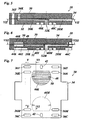
- Fig. 1 is a sectional view of an ink jet printhead that may be considered to extend across the entire width of a page of a recording medium in the direction normal to the plane of the drawing.
- the main support structure of the printhead is formed by a profiled bar 12 that defines four ink ducts 14Y, 14K, 14M and 14C, one for each color, that extend lengthwise of the beam and are open to the bottom surface thereof.
- the printhead 10 is to operate with hot melt inks which have to be heated to a temperature of approximately 100°C in order to be kept in the liquid state. This is why the beam 12 also defines a recess for accommodating a heating device 16.
- An ink supply assembly of the printhead is formed by a sequence of ink distribution tiles 18 that are mounted on the bottom side of the beam 12 so as to embrace a part of the heating device and are arranged directly adjacent to one another so as to continuously cover the entire length of the beam 12.
- the discharge units 22 are configured as chips or tiles and are butted against one another so as to form a continuous row extending along the bottom of the printhead and to form four continuous nozzle lines 26, one for each color, with nozzles arranged with a uniform pitch.
- each ink distribution tile 18 carries a plurality of discharge units 22.
- the discharge units that are arranged adjacent to one another on neighboring tiles 18 are also butted against one another so as to provide a continuous pattern of nozzles.
- the discharge units 22 may be configured as micro-electromechanical systems (MEMS), for example.
- MEMS micro-electromechanical systems
- the tiles could be trapezoidal or T-shaped and could be arranged with alternatingly inverse orientations, so that the tiles would overlap in longitudinal direction of the printhead. Then, the parts of the nozzle lines 26 formed on each tile could be staggered in transverse direction of the printhead, and the offsets would be compensated by appropriately controlling the timings and which the nozzles are fired.
- the print resolution of the printhead 10 may be larger than the pitch of nozzles in the nozzle lines 26 and may for example be twice that pitch.
- the print resolution may be as high as 300 dpi even when the pitch of the nozzles in each nozzle line 26 is only 150 nozzles per inch.
- the printhead 10 as a whole is oscillated in longitudinal direction by half the pitch. Due the mass of the inertia of the liquid ink, such movements of the printhead may however induce pressure fluctuations or oscillations in the ink contained in the ink ducts and in the ink distribution tiles 18.
- the main purpose of the ink distribution tiles 18 is to supply and distribute the inks of each color to the appropriate nozzles of the discharge units 22. Further, the ink supply system should have a certain compliance so as to be able to respond to varying demands for ink in the various regions of the printhead, without causing large variations in the velocity and pressure of the ink flows. Another purpose of the ink supply assembly according to this embodiment is to attenuate pressure fluctuations in the ink that may be induced by the oscillations of the printhead that have been mentioned above.
- Fig. 3 shows a schematic cross-section of an ink distribution tile 18 that has only a single ink passage 28 for ink of one colour.
- the tile 18 has a sandwich structure formed by a rigid upper plate member 30, a rigid lower plate member 32 and a thin polyimide film 34 interposed therebetween.
- An inlet port 36 for the ink is formed in the upper plate member 30 so as to be connected to one of the ink ducts 14Y, 14K, 14M, 14C.
- An outlet port 38 is formed in the lower plate member 32 for being connected to one of the discharge units 22.
- the ink passage 28 is formed by a recess in the top surface of the lower plate member 32 that is covered by the foil 34 and communicates with the inlet port 36 via a through-hole in the foil 34.
- the upper plate member 30 has a recess in its lower surface, and this recess defines a pressure equalization chamber, designated as "compliance chamber" 40, that is separated from the ink passage 28 by a part of the foil 34.
- the compliance chamber 40 is open to the atmosphere through a vent hole 42 and, consequently, is always kept under atmospheric pressure.
- the foil 34 may flex into the compliance chamber 40 in order to absorb the pressure fluctuation, as has been indicated in phantom lines in Fig. 3 .
- the compliance chamber 40 always acts to smoothen-out fluctuations in the pressure and ink flow in the ink passage 28.
- the compliance chamber 40 is integrated in the sandwich structure of the ink distribution tile 18 and does not increase the space requirement for this tile.
- ink passages that are partly bounded by a flexible membrane are generally known in ink jet printers, namely in the ink discharge unit, and are frequently employed for creating pressure pulses in the ink for the purpose of generating ink drops.
- the structure that is proposed in this application is provided upstream of the ink discharge unit and is integrated in the ink distribution assembly for the purpose of smoothening the pressure in the liquid ink.
- Fig. 4 shows another possible configuration of the ink distribution tile 18.
- a vented pressure equalization chamber which will briefly be termed “air chamber” 44 hereinafter, is formed in the lower plate member 32 and separated from the ink passage 28 by a rigid wall.
- the upper plate member 30 forms an ink chamber 46 that is opposed to the air chamber 44 and separated therefrom by a part of the foil 34.
- the ink chamber 46 and the ink duct 28 communicate with one another via a through-hole 48 in the foil 34.
- the ink chamber 46 is filled with liquid ink, although, considering the flow of ink from the inlet 36 to the outlet 28, it forms a dead end.
- ink cavity shall be used hereinafter for the combination of the ink chamber 46 and the ink passage 28.
- the through-hole 48 forms a flow-restriction that increases the flow resistance to be overcome by the liquid flowing into and out of the ink chamber 46.
- a part of the energy of the pressure oscillations is dissipated at the flow restriction, and by suitably dimensioning this flow restriction, the flow resistance may be adjusted such that pressure oscillations in a predominant frequency range are damped critically.
- the flow restriction may be adjusted to the frequency of oscillations that are induced by the oscillating movement that is imparted to the printhead 10 in order to increase the print resolution thereof.
- the ink distribution tile 18 has a sandwich structure composed of three plate members with thin foils interposed therebetween.
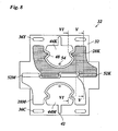
- Fig. 5 shows only the first or upper plate member 30, the second (central) plate member 32 and the foil 34 interposed therebetween.
- Fig. 6 is a sectional view of the same components of the tile 18, but taken at another sectional plane, as has been indicated in Figs. 7 and 8 .
- Fig. 7 shows the entire first foil 34 in a view from below and also shows (in phantom lines) the structures on the bottom side of the first plate member 30 that are hidden by this foil.
- the first plate member 3D and the foil 34 form two symmetrically arranged inlet ports 36Y for yellow ink, two inlet ports 36K for black ink and, at the opposite end of the tile, two inlet ports 36M and 36C for inks in magenta and cyan, respectively.
- suffixes Y, C, M and K behind a reference number will indicate the color of the ink in the supply system to which the item indicated by the reference number belongs.
- Vent holes 42 are formed through the first plate member 30 and the first foil 34.
- An ink chamber 46K for black ink is formed in the bottom side of the first plate member 30 and covered by the foil 34. In this ink chamber, the foil is supported by two islands 50 in the vicinity of through-holes 48.
- Another ink chamber 46M for ink in magenta is also formed in the bottom surface of the first plate member 30 and has a configuration mirror-symmetric to that of the ink chamber 46K.
- the through-hole 48 and the island 50 of the ink chamber 46K are also shown in the sectional view in Fig. 6 .
- Fig. 8 shows the top surface of the second plate member 32.
- Ink passages 28K and 28M are connected to the inlet ports 36K and 36M, respectively and are formed by recesses in the top surface of the plate member 32 that are symmetric under a 180° rotation.
- each of the ink passages 28K, 28M is connected to two slot-like ports 52K, 52M that are open to the bottom surface of the plate member 32.
- the ports 52K and 52M are arranged alternatingly on the central axis of the tile.
- Each of the ink passages 28K, 28M surrounds an air chamber 44K, 44M that is essentially congruent with a respective one of the ink chambers 46K and 46M from which it is separated by the foil 34 ( Fig. 6 ).
- the through-holes or flow restrictions 48 that connect the ink passages to their respective ink chambers are formed in bay portions of the ink passages 28K, 28M that project into the air chambers, as is shown in Fig. 8 .
- Each of the air chambers 44K, 44M is connected to one of the vent holes 42 that have been shown in Fig. 7 and is open to the bottom side of the plate member 32 via another vent hole 54.
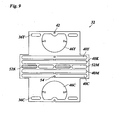
- Fig. 9 is a bottom view of the second plate member 32 that is penetrated by the inlet ports 36Y and 36C, by downward extensions of the vent holes 42 and by the slot-like ports 52K and 52M (whose left/right positions are inverted because one now looks at the bottom surface of the plate member).
- Recesses in the bottom surface of this plate member form ink chambers 46Y and 46C which have the same configuration as the ink cambers 46K and 46M in Fig. 7 , with the only difference that they are slightly offset towards the outer edges of the tile.
- Additional recesses in the bottom surface of the second plate member 32 form four elongated compliance chambers 40Y, 40K, 40M and 40C that extend in parallel with the alternating line of ports 52K and 52M.
- the two compliance chambers formed on either side of the ports 52K, 52M are interconnected with one another and, via the vent holes 54, with the air chambers 44K and 44M on the top side of the plate member 32.
- the layer structure that has been described so far is disposed on a second foil 56 and a third plate member 58 that are not shown in Figs. 5 and 6 but in Figs. 12 and 13 .
- FIG. 10 is a top plan view of the second foil 56 and shows also (in phantom lines) the structures of the third plate member 58 that are hidden by that foil.
- the foil 56 is penetrated by the inlet ports 36Y and 36C, through-holes 48, and the ports 52K and 52M. These latter ports communicate, via slanting passages 60, with elongated outlet ports 38K and 38M that pass through the third plate member 58.
- the top surface of the plate member 58 forms ink passages 28Y and 28C which connect the inlet ports 36Y, 36C to elongated outlet ports 38Y and 38C that pass through the plate member 58 and extend in parallel with the outlet ports 38K and 38M. Further, the through-holes 48 in the foil 56 connect the ink passages 28Y and 28C to the ink chambers 46Y and 46C, respectively, that are formed in the bottom surface of the second plate member 32 ( Fig. 9 ).
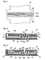
- Fig. 11 is a bottom view of the central part of the third plate member 58 and shows the four outlet ports 38Y, 38K, 38M and 38C which take the form of narrow parallel slots through which inks of all four colors are supplied to the discharge units 22 ( Fig. 2 ) that are placed on this ink distribution tile 18.
- Fig. 12 illustrates the path of black ink from the ink passage 28K via the port 52K formed in the second plate member 32 and the third foil 56 and, finally, through the outlet port 38K.
- the top part of this outlet port 38K is enlarged to form the two slanting passages 60 (see also Fig. 10 ) which connect to the ports 52K.
- Fig. 13 shows the plate member 58 in a sectional plane offset from the slanting passages 60.
- the outlet port 38M for magenta ink has essentially the same configuration.
- the mouths of the outlet ports in the lower surface of the plate member 58 are covered by a perforated foil 64 which helps to smoothen-out any possible disturbances in the flow of ink that may be caused by the separating walls between the windows 62 and the inclined passages 60, respectively.
- each of the compliance chambers 40Y, 40C extends right above the corresponding outlet port 38Y, 38C, so that varying demands of ink of the discharge units 22 can be buffered efficiently.
- the ink chamber 46Y and the air chamber 44Y are separated by the second foil 56 and, together with the flow-restricting through-hole 48 interconnecting the ink chamber 46Y and the ink passage 28Y, are effective to attenuate pressure oscillations in the yellow ink.
- the ink chamber 46C and the air chamber 44C as well as the ink chambers 46K, 46M and air chambers 44K, 44M on opposite sides of the second foil 34 have equivalent functions.
- the ink chambers 46Y-C form dead ends in the ink flow paths, a certain circulation and gradual replacement of the ink contained therein is made possible by providing two through-holes 48 for each of these ink chambers.
- the foils 34 and 56 used in this embodiment should on the one hand have a suitable strength and on the other hand have a sufficient resiliency in view of the damper and compliance functions and should be chemically inert.
- An example of a suitable material is polyimide resin.
- the plate members 30, 32 and 58 may for example be formed of graphite that can suitably be machined by laser machining techniques or the like. This material has the advantage that is has a high thermal stability, good heat conductivity and a thermal expansion coefficient that matches with the one of the ink discharge units 22 when the latter are formed by silicon MEMS.
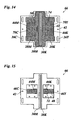
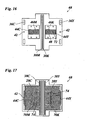
- Figs. 14 to 17 illustrate an ink distribution tile according to a second embodiment of the invention.
- This tile is formed by a sandwich structure of plate members 66, 68 and polyimide foils (not shown) interposed therebetween and disposed on the top and bottom of the structure.
- Fig. 14 is a top view of the top plate member 66
- Fig. 15 is a bottom view thereof
- Fig. 16 is top view of the second plate member 68
- Fig. 17 is a bottom view of the second plate member.
- recessed portions are indicated as hatched areas.
- the first plate member 66 has four through-holes serving as inlet ports 36Y and 36C for yellow and cyan ink.
- the foil (not shown) covering the top surface of this plate member 66 is formed with eight elongate through-holes of which four are aligned with the inlet ports 36Y, 36C and the other four are arranged in similar pattern as in Fig. 7 and directly serve as inlet ports for black and magenta inks.
- the black and magenta inks enter into ink passages 28K and 28M, which are connected to slot-like outlet ports 38K, 38M which penetrate both plate members 66 and 68 and extend in parallel along the center line of the tile.
- the top surface of the plate member 66 separates from the ink passages 28K, 28M, the top surface of the plate member 66 defines first portions of air chambers 44K and 44M and connection chambers 70Y and 70C.
- recessed portions in the bottom side of the plate member 66 form second portions of the air chambers 44K and 44M as well as ink chambers 46Y and 46C.
- the first and second portions of the air chambers 44K and 44M are connected to one another via through-holes 72 penetrating the first plate member 66.
- through-holes 48 connect the connection chambers 70Y and 70C to their respective ink chambers 46Y and 46C.
- the first portions of the air chambers 44K and 44M on the top surface of the plate member 66 are open to the atmosphere via through-holes formed in the foil that covers this plate member. Additional vent holes 42 pass through this foil, through the first plate member 66, the second foil (not shown) intervening between the two plate members, and the second plate member 68 and vent air chambers 44Y, 44C at the bottom surface of the second plate member 68.
- the second plate member 68 is also penetrated by the inlet ports 36Y and 36C. Recessed portions in the top surface of this plate member 68 define ink chambers 46K and 46M which communicate, via through-holes 48, with connection chambers 70K and 70M formed in the bottom surface of the second plate member 68, as is shown in Fig. 17 . Aligned through-holes 74 of both plate members 66, 68 establish a communication between the connection chambers 70K, 70M in Fig. 17 and the ink passages 28K and 28M in Fig. 14 . As is further shown in Figs. 14 and 17 , the foils covering the top surface of the plate member 66 and the bottom surface of the plate member 68 are supported by islands 50 in the vicinity of the through-holes 74.
- Black ink that has entered into the ink passage 28K will enter into the connection chamber 70K and from there, via the flow-restricting through-hole 48, into the ink chamber 46K formed in the top surface of the plate member 68.
- This ink chamber 46K is congruent with and opposed to the air chamber 44K on the bottom side of the plate member 66 ( Fig. 15 ), and the ink chamber and the air chamber are separated by the flexible foil interposed between the two plate members.
- pressure fluctuations in the black ink can be attenuated similarly as in the first embodiment.
- magenta ink introduced into the ink passage 28M The inks in yellow and cyan that have entered through the inlet ports 36Y and 36C ( Fig. 14 ) will be introduced into ink passages 28Y and 28C formed in the bottom surface of the second plate member 68 ( Fig. 17 ), from where they will enter into slot-like outlet ports 38Y and 38C.
- the foil (not shown) covering the bottom surface of the plate member 68 will close the ink passages 28Y and 28C but will leave open the outlet ports, so that the inks of all four colors may be supplied to the ink discharge units.
- the ink may also flow, via aligned through-holes 74, into the connecting chambers 70Y, 70C ( Fig. 14 ) and from there into the ink chambers 46Y and 46C ( Fig. 15 ).
- These ink chambers are opposed to second portions of the air chambers 44Y and 44C which communicate with first portions of these air chambers formed in the bottom surface of the second plate member 68 ( Fig. 17 ).
- These first portions of the air chambers 44Y, 44C are vented through the vent holes 42.
- the air chambers 44Y-44C provide also for the necessary compliance of the ink supply system. Thanks to the described configuration of the plate members 66, 68, it is possible to mold these plate members from polymeric or ceramic materials, for example.
Landscapes
- Particle Formation And Scattering Control In Inkjet Printers (AREA)
- Ink Jet (AREA)
Claims (11)
- Tintenstrahlzufuhranordnung mit wenigstens einem Einlassport (36), wenigstens einem Auslassport (38), der mit dem Einlassport über eine Tintenkavität (28, 46) verbunden ist und dazu eingerichtet ist, mit einer Tintenabgabeeinheit (22) einer Tintenstrahlvorrichtung verbunden zu werden, wobei die Zufuhranordnung eine Sandwichstruktur hat, gebildet durch wenigstens zwei plattenförmige Bauteile (30, 32, 58; 66, 68) und eine dazwischen eingefügte Folie (34, 56), die einen Teil hat, der eine Wand der Tintenkavität (28, 46) bildet, wobei wenigstens eines der plattenförmigen Bauteile (30, 32, 58; 66, 68) eine Druckausgleichskammer (44) begrenzt, die an die Tintenkavität (28, 46) angrenzt und von dieser durch die genannte Folie (34, 56) getrennt ist, dadurch gekennzeichnet, dass die Tintenkavität einen Tintenkanal (28), der den Einlassport (36) mit dem Auslassport (38) verbindet, und eine Tintenkammer (46) aufweist, die über eine Strömungsbegrenzung (48) mit der Tintenkammer (46) in Verbindung steht und in der Tintenströmung eine Sackgasse bildet, und dass die Folie (34) die Tintenkammer (46) von der Druckausgleichskammer (44) trennt.
- Anordnung nach Anspruch 1, bei der eine erste Druckausgleichskammer (40) benachbart zu einem stromabwärtigen Ende des Tintenkanals (28) angeordnet und davon durch die genannte Folie (34, 56) getrennt ist, und eine zweite Druckausgleichskammer (44) gegenüberliegend zu der Tintenkammer (46) angeordnet ist.
- Anordnung nach Anspruch 1 oder 2, bei der die Strömungsbegrenzung (48) durch ein Loch in der Folie (34) gebildet wird.
- Anordnung nach einem der vorstehenden Ansprüche, mit mehreren Tintenkanälen (28Y, 28C, 28M, 28K) für Tinten in verschiedenen Farben, wobei jedem Tintenkanal wenigstens eine Druckausgleichskammer (40Y-K, 44 Y-K) zugeordnet ist.
- Anordnung nach Anspruch 4, bei der die Auslassports (38Y-K), die mit den verschiedenen Tintenkanälen verbunden sind, als parallele Schlitze ausgebildet sind.
- Anordndung nach Anspruch 4 oder 5, bei dem jedem der Tintenkanäle (28Y-K) eine erste Druckausgleichskammer (40Y-K), eine zweite Druckausgleichskammer (44Y-K) und eine Tintenkammer (46Y-K) zugeordnet ist, die der zweiten Druckausgleichkammer gegenüberliegt und mit dem Tintenkanal (28Y-K) über eine Strömungsbegrenzung (48) verbunden ist.
- Anordnung nach einem der Ansprüche 4 bis 6, mit einem ersten, einem zweiten und einem dritten plattenförmigen Bauteil (30, 32, 58), einer ersten Folie (34), die zwischen den ersten und zweiten plattenförmigen Bauteilen eingefügt ist, und einer zweiten Folie (56), die zwischen den zweiten und dritten plattenförmigen Bauteilen eingefügt ist, wobei wenigstens eine Druckausgleichskammer (44K, 44M) und eine Tintenkammer (46K, 46M), die einem der Tintenkanäle zugeordnet sind, auf entgegengesetzten Seiten der ersten Folie (34) angeordnet sind und wenigstens eine andere Druckausgleichskammer (44Y, 44C) und eine andere Tintenkammer (46Y, 46C) auf entgegengesetzten Seiten der zweiten Folie (56) angeordnet sind.
- Anordnung nach Anspruch 7, bei der die Tintenzufuhrports (36Y-K) in dem ersten plattenförmigen Bauteil (30) gebildet sind, die Auslassports (38Y-K) in dem dritten plattenförmigen Bauteil (58) gebildet sind, und jeder von wenigstens zwei Tintenkanälen (28K, 28M), die angrenzend an die erste Folie (34) angeordnet sind, mit ihren Auslassports (38K, 38M) über wenigstens zwei längliche Ports (52K, 52M) verbunden sind, die in dem zweiten plattenförmigen Bauteil (32) gebildet sind, wobei die länglichen Ports der wenigstens zwei Tintenkanäle miteinander ausgerichtet und abwechselnd angeordnet sind.
- Anordnung nach Anspruch 4 oder 5, bei der
wenigstens ein erster Tintenkanal (28K, 28M) in einem ersten plattenförmigen Bauteil (66) gebildet und mit einem Auslassport (38K, 38M) verbunden ist, der ein angrenzendes zweites plattenförmiges Bauteil (68) und eine zwischen den beiden plattenförmigen Bauteilen eingefügte Folie durchdringt,
wenigstens ein zweiter Tintenkanal (28Y, 28C) in dem zweiten plattenförmigen Bauteil (68) gebildet und mit Einlassports (36Y, 36C) verbunden ist, die das erste plattenförmige Bauteil (66) und die genannte Folie durchdringen,
eine erste Tintenkammer (46K, 46M) mit dem ersten Tintenkanal (28K, 28M) verbunden und benachbart zu der genannten Folie in dem zweiten plattenförmigen Bauteil (68) gebildet ist,
eine erste Druckausgleichskammer (44K, 44M) benachbart zu der genannten Folie und der ersten Tintenkammer gegenüber liegend in dem ersten plattenförmigen Bauteil (66) gebildet ist,
eine zweite Tintenkammer (46Y, 46C) mit dem zweiten Tintenkanal (28Y, 28C) verbunden und angrenzend an die genannte Folie in dem ersten plattenförmigen Bauteil (66) gebildet ist, und
eine zweite Druckausgleichskammer (44Y, 44C) angrenzend zu der genannten Folie und gegenüberliegend zu der zweiten Tintenkammer in dem zweiten plattenförmigen Bauteil (68) gebildet ist. - Tintenstrahldrucker, gekennzeichnet durch eine Tintenzufuhranordnung (18) nach einem der vorstehenden Ansprüche.
- Tintenstrahldrucker nach Anspruch 10, bei dem die Tintenzufuhranordnung aufgebaut ist aus einer Vielzahl getrennter Tintenverteilungskacheln (18), die einen identischen Aufbau haben und in einer Reihe angeordnet sind, um Tinte zu wenigstens zwei durchgehenden Düsenzeilen (26) zuzuführen, die sich über die Vielzahl der Kacheln erstrecken.
Priority Applications (1)
| Application Number | Priority Date | Filing Date | Title |
|---|---|---|---|
| EP08166319A EP2052861B1 (de) | 2007-10-23 | 2008-10-10 | Tintenzufuhrbauteil für eine Tintenstrahldruckvorrichtung |
Applications Claiming Priority (2)
| Application Number | Priority Date | Filing Date | Title |
|---|---|---|---|
| EP07119087 | 2007-10-23 | ||
| EP08166319A EP2052861B1 (de) | 2007-10-23 | 2008-10-10 | Tintenzufuhrbauteil für eine Tintenstrahldruckvorrichtung |
Publications (2)
| Publication Number | Publication Date |
|---|---|
| EP2052861A1 EP2052861A1 (de) | 2009-04-29 |
| EP2052861B1 true EP2052861B1 (de) | 2010-09-29 |
Family
ID=39018174
Family Applications (1)
| Application Number | Title | Priority Date | Filing Date |
|---|---|---|---|
| EP08166319A Ceased EP2052861B1 (de) | 2007-10-23 | 2008-10-10 | Tintenzufuhrbauteil für eine Tintenstrahldruckvorrichtung |
Country Status (5)
| Country | Link |
|---|---|
| US (1) | US8303095B2 (de) |
| EP (1) | EP2052861B1 (de) |
| JP (1) | JP5468232B2 (de) |
| AT (1) | ATE482828T1 (de) |
| DE (1) | DE602008002798D1 (de) |
Families Citing this family (4)
| Publication number | Priority date | Publication date | Assignee | Title |
|---|---|---|---|---|
| WO2016030247A1 (en) | 2014-08-26 | 2016-03-03 | Oce-Technologies B.V. | Multi-chip print head |
| JP6862741B2 (ja) * | 2016-09-29 | 2021-04-21 | ブラザー工業株式会社 | 液体吐出装置及び液体供給ユニット |
| US10286672B2 (en) * | 2016-11-18 | 2019-05-14 | Ricoh Company, Ltd. | Liquid discharge head, liquid discharge device, liquid supply member, and liquid discharge apparatus |
| TWI789529B (zh) | 2018-07-30 | 2023-01-11 | 瑞士商西克帕控股有限公司 | 多晶片模組(mcm)組件 |
Family Cites Families (16)
| Publication number | Priority date | Publication date | Assignee | Title |
|---|---|---|---|---|
| JPS6317056A (ja) * | 1986-07-09 | 1988-01-25 | Fujitsu Ltd | インクジエツトプリンタの印字ヘツド |
| JPH07137262A (ja) * | 1993-11-17 | 1995-05-30 | Canon Inc | インクジェット記録ヘッドおよびインクジェット記録装置 |
| DE19545775C2 (de) * | 1995-12-07 | 1999-03-25 | Pelikan Produktions Ag | Flüssigkeitspatrone, insbesondere Tintenpatrone für einen Druckkopf eines Ink-Jet-Printers |
| JP2000033713A (ja) * | 1998-07-17 | 2000-02-02 | Seiko Epson Corp | インクジェット印刷ヘッド及びインクジェットプリンタ |
| AUPR399601A0 (en) | 2001-03-27 | 2001-04-26 | Silverbrook Research Pty. Ltd. | An apparatus and method(ART108) |
| CN1189324C (zh) * | 2001-08-21 | 2005-02-16 | 精工爱普生株式会社 | 喷墨打印机中的打印头部件 |
| ATE326348T1 (de) * | 2001-10-05 | 2006-06-15 | Canon Kk | Tintenbehälter, flüssigkeitszufuhrvorrichtung und aufzeichnungsvorrichtung |
| DE60303227T2 (de) * | 2002-02-15 | 2006-09-28 | Brother Kogyo K.K., Nagoya | Verfahren zur Herstellung eines Tintenstrahlkopfes |
| JP4457591B2 (ja) * | 2002-12-13 | 2010-04-28 | セイコーエプソン株式会社 | 差圧弁ユニット、液体カートリッジおよび液体カートリッジ組立方法 |
| JP2003159813A (ja) * | 2002-12-13 | 2003-06-03 | Seiko Epson Corp | インクジェット式記録装置、及びインクカートリッジ |
| WO2004085161A1 (en) * | 2003-03-24 | 2004-10-07 | Ricoh Company, Ltd. | Recording head, carriage and image forming apparatus |
| JP4284516B2 (ja) * | 2003-10-24 | 2009-06-24 | ブラザー工業株式会社 | インクジェットプリンタ |
| JP4069864B2 (ja) * | 2003-12-25 | 2008-04-02 | ブラザー工業株式会社 | インクジェットヘッド |
| JP4543952B2 (ja) | 2004-11-17 | 2010-09-15 | ブラザー工業株式会社 | インクジェットヘッド |
| JP4729957B2 (ja) * | 2005-03-24 | 2011-07-20 | 富士ゼロックス株式会社 | 液滴吐出ヘッドバー、液滴吐出装置、及び、液滴吐出ヘッドバー製造方法 |
| US8197048B2 (en) * | 2006-04-26 | 2012-06-12 | Ricoh Company, Ltd. | Image forming apparatus |
-
2008
- 2008-10-10 EP EP08166319A patent/EP2052861B1/de not_active Ceased
- 2008-10-10 AT AT08166319T patent/ATE482828T1/de not_active IP Right Cessation
- 2008-10-10 DE DE602008002798T patent/DE602008002798D1/de active Active
- 2008-10-20 JP JP2008269297A patent/JP5468232B2/ja not_active Expired - Fee Related
- 2008-10-22 US US12/289,191 patent/US8303095B2/en active Active
Also Published As
| Publication number | Publication date |
|---|---|
| US8303095B2 (en) | 2012-11-06 |
| ATE482828T1 (de) | 2010-10-15 |
| US20090102899A1 (en) | 2009-04-23 |
| JP5468232B2 (ja) | 2014-04-09 |
| EP2052861A1 (de) | 2009-04-29 |
| DE602008002798D1 (de) | 2010-11-11 |
| JP2009101689A (ja) | 2009-05-14 |
Similar Documents
| Publication | Publication Date | Title |
|---|---|---|
| US5463412A (en) | Liquid jet recording head with multiple liquid chambers | |
| US10538087B2 (en) | Liquid ejecting head and liquid ejecting apparatus | |
| EP1034931B1 (de) | Aufzeichnungskopf des Tintenstrahltyps | |
| US8201925B2 (en) | Ink jet print head having board with varying heat resistance | |
| EP2186642B1 (de) | Flüssigkeitsabgabekopf und Flüssigkeitsabgabeverfahren | |
| EP2052861B1 (de) | Tintenzufuhrbauteil für eine Tintenstrahldruckvorrichtung | |
| AU2005211710A1 (en) | High resolution ink jet printhead | |
| US8083325B2 (en) | Liquid ejection recording head having element substrate with plural supply ports | |
| EP1034930B1 (de) | Tintenstrahlaufzeichnungskopf | |
| EP1078749A2 (de) | Tintenstrahlaufzeichnungsvorrichtung und Tintenstrahlaufzeichnungskopf | |
| US9434156B2 (en) | Method of inkjet printing and maintaining nozzle hydration | |
| JP2005193579A (ja) | インクジェット記録装置 | |
| JPH10217452A (ja) | インクジェット式記録ヘッド | |
| US10668725B2 (en) | Supply manifold in a printhead | |
| JP2009132080A (ja) | インクジェット記録ヘッド | |
| US20110242214A1 (en) | Liquid jetting head and ink-jet printer | |
| JP4766626B2 (ja) | インクジェット記録ヘッド、及びインクジェット記録装置 | |
| EP3536508B1 (de) | Druckkopf | |
| JP4046970B2 (ja) | 液体吐出ヘッドならびにヘッドカートリッジおよび画像形成装置 | |
| JP4385667B2 (ja) | インクジェット式記録ヘッドおよびインクジェット式記録ヘッドを有する印刷装置。 | |
| EP0985536B1 (de) | Aufzeichnungskopf des Tintenstrahltypes | |
| US20230311499A1 (en) | Liquid ejection head | |
| JP4276329B2 (ja) | インクジェットヘッド | |
| US11155089B2 (en) | Liquid ejection head | |
| US20230311500A1 (en) | Liquid ejection head and liquid ejection apparatus |
Legal Events
| Date | Code | Title | Description |
|---|---|---|---|
| PUAI | Public reference made under article 153(3) epc to a published international application that has entered the european phase |
Free format text: ORIGINAL CODE: 0009012 |
|
| AK | Designated contracting states |
Kind code of ref document: A1 Designated state(s): AT BE BG CH CY CZ DE DK EE ES FI FR GB GR HR HU IE IS IT LI LT LU LV MC MT NL NO PL PT RO SE SI SK TR |
|
| AX | Request for extension of the european patent |
Extension state: AL BA MK RS |
|
| 17P | Request for examination filed |
Effective date: 20091029 |
|
| AKX | Designation fees paid |
Designated state(s): AT BE BG CH CY CZ DE DK EE ES FI FR GB GR HR HU IE IS IT LI LT LU LV MC MT NL NO PL PT RO SE SI SK TR |
|
| GRAP | Despatch of communication of intention to grant a patent |
Free format text: ORIGINAL CODE: EPIDOSNIGR1 |
|
| GRAS | Grant fee paid |
Free format text: ORIGINAL CODE: EPIDOSNIGR3 |
|
| GRAA | (expected) grant |
Free format text: ORIGINAL CODE: 0009210 |
|
| AK | Designated contracting states |
Kind code of ref document: B1 Designated state(s): AT BE BG CH CY CZ DE DK EE ES FI FR GB GR HR HU IE IS IT LI LT LU LV MC MT NL NO PL PT RO SE SI SK TR |
|
| REG | Reference to a national code |
Ref country code: GB Ref legal event code: FG4D |
|
| REG | Reference to a national code |
Ref country code: CH Ref legal event code: EP |
|
| REG | Reference to a national code |
Ref country code: IE Ref legal event code: FG4D |
|
| REF | Corresponds to: |
Ref document number: 602008002798 Country of ref document: DE Date of ref document: 20101111 Kind code of ref document: P |
|
| REG | Reference to a national code |
Ref country code: NL Ref legal event code: T3 |
|
| PG25 | Lapsed in a contracting state [announced via postgrant information from national office to epo] |
Ref country code: NO Free format text: LAPSE BECAUSE OF FAILURE TO SUBMIT A TRANSLATION OF THE DESCRIPTION OR TO PAY THE FEE WITHIN THE PRESCRIBED TIME-LIMIT Effective date: 20101229 Ref country code: LT Free format text: LAPSE BECAUSE OF FAILURE TO SUBMIT A TRANSLATION OF THE DESCRIPTION OR TO PAY THE FEE WITHIN THE PRESCRIBED TIME-LIMIT Effective date: 20100929 Ref country code: AT Free format text: LAPSE BECAUSE OF FAILURE TO SUBMIT A TRANSLATION OF THE DESCRIPTION OR TO PAY THE FEE WITHIN THE PRESCRIBED TIME-LIMIT Effective date: 20100929 Ref country code: FI Free format text: LAPSE BECAUSE OF FAILURE TO SUBMIT A TRANSLATION OF THE DESCRIPTION OR TO PAY THE FEE WITHIN THE PRESCRIBED TIME-LIMIT Effective date: 20100929 |
|
| LTIE | Lt: invalidation of european patent or patent extension |
Effective date: 20100929 |
|
| PG25 | Lapsed in a contracting state [announced via postgrant information from national office to epo] |
Ref country code: HR Free format text: LAPSE BECAUSE OF FAILURE TO SUBMIT A TRANSLATION OF THE DESCRIPTION OR TO PAY THE FEE WITHIN THE PRESCRIBED TIME-LIMIT Effective date: 20100929 Ref country code: SI Free format text: LAPSE BECAUSE OF FAILURE TO SUBMIT A TRANSLATION OF THE DESCRIPTION OR TO PAY THE FEE WITHIN THE PRESCRIBED TIME-LIMIT Effective date: 20100929 |
|
| PG25 | Lapsed in a contracting state [announced via postgrant information from national office to epo] |
Ref country code: GR Free format text: LAPSE BECAUSE OF FAILURE TO SUBMIT A TRANSLATION OF THE DESCRIPTION OR TO PAY THE FEE WITHIN THE PRESCRIBED TIME-LIMIT Effective date: 20101230 Ref country code: LV Free format text: LAPSE BECAUSE OF FAILURE TO SUBMIT A TRANSLATION OF THE DESCRIPTION OR TO PAY THE FEE WITHIN THE PRESCRIBED TIME-LIMIT Effective date: 20100929 Ref country code: SE Free format text: LAPSE BECAUSE OF FAILURE TO SUBMIT A TRANSLATION OF THE DESCRIPTION OR TO PAY THE FEE WITHIN THE PRESCRIBED TIME-LIMIT Effective date: 20100929 |
|
| PG25 | Lapsed in a contracting state [announced via postgrant information from national office to epo] |
Ref country code: RO Free format text: LAPSE BECAUSE OF FAILURE TO SUBMIT A TRANSLATION OF THE DESCRIPTION OR TO PAY THE FEE WITHIN THE PRESCRIBED TIME-LIMIT Effective date: 20100929 Ref country code: IT Free format text: LAPSE BECAUSE OF FAILURE TO SUBMIT A TRANSLATION OF THE DESCRIPTION OR TO PAY THE FEE WITHIN THE PRESCRIBED TIME-LIMIT Effective date: 20100929 Ref country code: MC Free format text: LAPSE BECAUSE OF NON-PAYMENT OF DUE FEES Effective date: 20101031 Ref country code: SK Free format text: LAPSE BECAUSE OF FAILURE TO SUBMIT A TRANSLATION OF THE DESCRIPTION OR TO PAY THE FEE WITHIN THE PRESCRIBED TIME-LIMIT Effective date: 20100929 Ref country code: EE Free format text: LAPSE BECAUSE OF FAILURE TO SUBMIT A TRANSLATION OF THE DESCRIPTION OR TO PAY THE FEE WITHIN THE PRESCRIBED TIME-LIMIT Effective date: 20100929 Ref country code: IS Free format text: LAPSE BECAUSE OF FAILURE TO SUBMIT A TRANSLATION OF THE DESCRIPTION OR TO PAY THE FEE WITHIN THE PRESCRIBED TIME-LIMIT Effective date: 20110129 Ref country code: PT Free format text: LAPSE BECAUSE OF FAILURE TO SUBMIT A TRANSLATION OF THE DESCRIPTION OR TO PAY THE FEE WITHIN THE PRESCRIBED TIME-LIMIT Effective date: 20110131 Ref country code: CZ Free format text: LAPSE BECAUSE OF FAILURE TO SUBMIT A TRANSLATION OF THE DESCRIPTION OR TO PAY THE FEE WITHIN THE PRESCRIBED TIME-LIMIT Effective date: 20100929 |
|
| PG25 | Lapsed in a contracting state [announced via postgrant information from national office to epo] |
Ref country code: BE Free format text: LAPSE BECAUSE OF FAILURE TO SUBMIT A TRANSLATION OF THE DESCRIPTION OR TO PAY THE FEE WITHIN THE PRESCRIBED TIME-LIMIT Effective date: 20100929 |
|
| PG25 | Lapsed in a contracting state [announced via postgrant information from national office to epo] |
Ref country code: ES Free format text: LAPSE BECAUSE OF FAILURE TO SUBMIT A TRANSLATION OF THE DESCRIPTION OR TO PAY THE FEE WITHIN THE PRESCRIBED TIME-LIMIT Effective date: 20110109 |
|
| PLBE | No opposition filed within time limit |
Free format text: ORIGINAL CODE: 0009261 |
|
| STAA | Information on the status of an ep patent application or granted ep patent |
Free format text: STATUS: NO OPPOSITION FILED WITHIN TIME LIMIT |
|
| PG25 | Lapsed in a contracting state [announced via postgrant information from national office to epo] |
Ref country code: PL Free format text: LAPSE BECAUSE OF FAILURE TO SUBMIT A TRANSLATION OF THE DESCRIPTION OR TO PAY THE FEE WITHIN THE PRESCRIBED TIME-LIMIT Effective date: 20100929 Ref country code: DK Free format text: LAPSE BECAUSE OF FAILURE TO SUBMIT A TRANSLATION OF THE DESCRIPTION OR TO PAY THE FEE WITHIN THE PRESCRIBED TIME-LIMIT Effective date: 20100929 |
|
| REG | Reference to a national code |
Ref country code: DE Ref legal event code: R097 Ref document number: 602008002798 Country of ref document: DE Effective date: 20110630 |
|
| PG25 | Lapsed in a contracting state [announced via postgrant information from national office to epo] |
Ref country code: IE Free format text: LAPSE BECAUSE OF NON-PAYMENT OF DUE FEES Effective date: 20101010 |
|
| PG25 | Lapsed in a contracting state [announced via postgrant information from national office to epo] |
Ref country code: MT Free format text: LAPSE BECAUSE OF FAILURE TO SUBMIT A TRANSLATION OF THE DESCRIPTION OR TO PAY THE FEE WITHIN THE PRESCRIBED TIME-LIMIT Effective date: 20100929 |
|
| PG25 | Lapsed in a contracting state [announced via postgrant information from national office to epo] |
Ref country code: CY Free format text: LAPSE BECAUSE OF FAILURE TO SUBMIT A TRANSLATION OF THE DESCRIPTION OR TO PAY THE FEE WITHIN THE PRESCRIBED TIME-LIMIT Effective date: 20100929 |
|
| PG25 | Lapsed in a contracting state [announced via postgrant information from national office to epo] |
Ref country code: LU Free format text: LAPSE BECAUSE OF NON-PAYMENT OF DUE FEES Effective date: 20101010 Ref country code: HU Free format text: LAPSE BECAUSE OF FAILURE TO SUBMIT A TRANSLATION OF THE DESCRIPTION OR TO PAY THE FEE WITHIN THE PRESCRIBED TIME-LIMIT Effective date: 20110330 Ref country code: BG Free format text: LAPSE BECAUSE OF FAILURE TO SUBMIT A TRANSLATION OF THE DESCRIPTION OR TO PAY THE FEE WITHIN THE PRESCRIBED TIME-LIMIT Effective date: 20100929 |
|
| PG25 | Lapsed in a contracting state [announced via postgrant information from national office to epo] |
Ref country code: TR Free format text: LAPSE BECAUSE OF FAILURE TO SUBMIT A TRANSLATION OF THE DESCRIPTION OR TO PAY THE FEE WITHIN THE PRESCRIBED TIME-LIMIT Effective date: 20100929 |
|
| REG | Reference to a national code |
Ref country code: CH Ref legal event code: PL |
|
| PG25 | Lapsed in a contracting state [announced via postgrant information from national office to epo] |
Ref country code: LI Free format text: LAPSE BECAUSE OF NON-PAYMENT OF DUE FEES Effective date: 20121031 Ref country code: CH Free format text: LAPSE BECAUSE OF NON-PAYMENT OF DUE FEES Effective date: 20121031 |
|
| PG25 | Lapsed in a contracting state [announced via postgrant information from national office to epo] |
Ref country code: BG Free format text: LAPSE BECAUSE OF FAILURE TO SUBMIT A TRANSLATION OF THE DESCRIPTION OR TO PAY THE FEE WITHIN THE PRESCRIBED TIME-LIMIT Effective date: 20101229 |
|
| REG | Reference to a national code |
Ref country code: FR Ref legal event code: PLFP Year of fee payment: 8 |
|
| REG | Reference to a national code |
Ref country code: FR Ref legal event code: PLFP Year of fee payment: 9 |
|
| REG | Reference to a national code |
Ref country code: FR Ref legal event code: PLFP Year of fee payment: 10 |
|
| PGFP | Annual fee paid to national office [announced via postgrant information from national office to epo] |
Ref country code: NL Payment date: 20171024 Year of fee payment: 10 |
|
| REG | Reference to a national code |
Ref country code: FR Ref legal event code: PLFP Year of fee payment: 11 |
|
| PGFP | Annual fee paid to national office [announced via postgrant information from national office to epo] |
Ref country code: DE Payment date: 20181019 Year of fee payment: 11 |
|
| PGFP | Annual fee paid to national office [announced via postgrant information from national office to epo] |
Ref country code: GB Payment date: 20181019 Year of fee payment: 11 Ref country code: FR Payment date: 20181022 Year of fee payment: 11 |
|
| REG | Reference to a national code |
Ref country code: NL Ref legal event code: MM Effective date: 20181101 |
|
| PG25 | Lapsed in a contracting state [announced via postgrant information from national office to epo] |
Ref country code: NL Free format text: LAPSE BECAUSE OF NON-PAYMENT OF DUE FEES Effective date: 20181101 |
|
| REG | Reference to a national code |
Ref country code: DE Ref legal event code: R119 Ref document number: 602008002798 Country of ref document: DE |
|
| PG25 | Lapsed in a contracting state [announced via postgrant information from national office to epo] |
Ref country code: DE Free format text: LAPSE BECAUSE OF NON-PAYMENT OF DUE FEES Effective date: 20200501 |
|
| GBPC | Gb: european patent ceased through non-payment of renewal fee |
Effective date: 20191010 |
|
| PG25 | Lapsed in a contracting state [announced via postgrant information from national office to epo] |
Ref country code: GB Free format text: LAPSE BECAUSE OF NON-PAYMENT OF DUE FEES Effective date: 20191010 Ref country code: FR Free format text: LAPSE BECAUSE OF NON-PAYMENT OF DUE FEES Effective date: 20191031 |