EP2050187B1 - Antrieb und verfahren - Google Patents
Antrieb und verfahren Download PDFInfo
- Publication number
- EP2050187B1 EP2050187B1 EP07786118.5A EP07786118A EP2050187B1 EP 2050187 B1 EP2050187 B1 EP 2050187B1 EP 07786118 A EP07786118 A EP 07786118A EP 2050187 B1 EP2050187 B1 EP 2050187B1
- Authority
- EP
- European Patent Office
- Prior art keywords
- setpoint
- limiter
- value
- closed
- time
- Prior art date
- Legal status (The legal status is an assumption and is not a legal conclusion. Google has not performed a legal analysis and makes no representation as to the accuracy of the status listed.)
- Active
Links
Images


Classifications
-
- H—ELECTRICITY
- H02—GENERATION; CONVERSION OR DISTRIBUTION OF ELECTRIC POWER
- H02P—CONTROL OR REGULATION OF ELECTRIC MOTORS, ELECTRIC GENERATORS OR DYNAMO-ELECTRIC CONVERTERS; CONTROLLING TRANSFORMERS, REACTORS OR CHOKE COILS
- H02P23/00—Arrangements or methods for the control of AC motors characterised by a control method other than vector control
- H02P23/04—Arrangements or methods for the control of AC motors characterised by a control method other than vector control specially adapted for damping motor oscillations, e.g. for reducing hunting
-
- H—ELECTRICITY
- H02—GENERATION; CONVERSION OR DISTRIBUTION OF ELECTRIC POWER
- H02P—CONTROL OR REGULATION OF ELECTRIC MOTORS, ELECTRIC GENERATORS OR DYNAMO-ELECTRIC CONVERTERS; CONTROLLING TRANSFORMERS, REACTORS OR CHOKE COILS
- H02P23/00—Arrangements or methods for the control of AC motors characterised by a control method other than vector control
- H02P23/0004—Control strategies in general, e.g. linear type, e.g. P, PI, PID, using robust control
Definitions
- the invention is therefore based on the object to improve the control properties of an electric drive.
- the object is achieved in the drive according to the features specified in claim 1 and in the method according to the features indicated in claim 15.
- Essential features of the invention in the drive are that it comprises an electric motor, which is fed by a converter, the converter comprising a time-discrete control structure which regulates the stator current of the electric motor by means of adjusting the voltage applied to the motor, whereby the current of the motor is detected discretely, wherein the control structure comprises a regulator whose actual value is a first current component of the current, wherein the setpoint specification of the controller is preceded by at least one setpoint limiter.
- the setpoint limiter can be executed in such a way that the setting limit of the converter, that is to say, for example, the voltage setting limit caused by the intermediate circuit voltage, is not exceeded.
- the control structure is executable such that the actual value is such that it reaches the setpoint applied to the actual controller setpoint after exactly one time step, ie time grid, but this setpoint value can be generated from the output signal of the setpoint limiter.
- a time delay element is arranged between the setpoint specification of the controller and the output value of the setpoint limitation, in particular for delaying by a single time step.
- the controller is assigned a pilot control, which adds to the output value of the controller a proportional to the time change of the setpoint specification size.
- the controller is a dead-beat controller, in particular adapted to the engine arranged in the controlled system.
- the advantage here is that the actual value at the controller input can reach the applied setpoint in a single time step, ie time grid.
- controller is a linear controller, such as P-controller, a PI controller or a PID controller, in particular with pilot control.
- P-controller a PI controller
- PID controller a PID controller
- the current components in a coordinate system are determined from the detected current.
- the advantage here is that an adapted coordinate system can be used, in particular a co-rotating, so that the computational effort is low.
- the converter comprises a control structure for each current component that is similar to the control structure for the first current component.
- the feedforward control is designed as a dead-beat control, that is to say that the motor arranged in the controlled system has an inverse behavior, in particular wherein the setting limit of the converter is not taken into account.
- the advantage here is that the feedforward control is so providable that the feedforward can already disappear in a time step, the essential deviations of the actual size of the setpoint size.
- the limiter has, as input values, the maximum and minimum values (max, min) and the time-delayed setpoint value I setpoint, the smaller value being determined from max and input, which is compared with the time-delayed output value of the limiter and of which the larger value becomes effective as the upper limit of the limiter member acting on the input, the greater value being determined from min and input, which is compared with the time-delayed output value of the limiter and of which the smaller value becomes effective as the lower limit of the limiter member acting on the input.
- the advantage here is that the limit values are dependent on the controller output and thus overshoots can be prevented.
- n numbered the time steps
- ( U max) is the voltage setting limit
- ( u r, n ) is the value of the controller output variable U
- K has the same value as in the feedforward control V.
- the advantage here is that parameters of the controlled system, such as K , And the setting limit U_max are considered such that an overshoot is suppressible.
- the actual value of a first current component of the current is regulated to a desired value specification, the setpoint input being the output of a setpoint limiter, where the manipulated variable of the regulator is the voltage applied to the motor.
- This vector can be represented in a coordinate system, such as flow coordinate system, rotor coordinate system or the like.
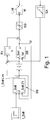
- the setpoint I setpoint and the actual value I_IST are fed to the current controller, which changes the manipulated variable in accordance with the control deviation.
- the voltage U that is to say the magnitude of the voltage vector of the supply of the motor M, is preferably the said manipulated variable.
- the setpoint input for the controller SR is supplied to the controller with a time delay. This makes it possible, since at the new time already the new setpoint specification is known that the control structure via a feedforward V temporally synchronous to the new setpoint input influences the output of the controller SR in the desired manner. This then causes according to the physical laws of the controlled system, comprising the motor M, a change of the detected current component actual value I_IST, which is supplied to the controller SR as an actual value. considered So if you have the time-discrete controller structure, it is clear that the actual value and the setpoint specification of the controller SR belong to the same time grid, ie time step.
- control structure thus has a controller whose setpoint specification is delayed in time, wherein the controller is connected in parallel with a dead-beat precontrol, which is effective in terms of time without delay.
- the manipulated variable U is subject to an adjustment limit, since in the motor supplying converter no arbitrarily high voltages can be produced. Nevertheless, an overshoot of the current value in the invention is avoidable and thus reaching the current limit and the associated emergency shutdown and error messages.
- the actual controller SR receives only the delayed setpoint specification and compares it with the more recent at least one time step actual value size.
- a setpoint limiter SB is used.
- This setpoint limiter SB prevents the setting limit of the manipulated variable from being exceeded.
- the desired value is limited such that the voltage setting limit SG is not exceeded, and this is done in such a way that no other disadvantages arise, such as instabilities of the control loop due to additional feedback.
- the setpoint limiter SB uses the output variable U of the controller as input variables, the non-delayed actual setpoint value I_Soll and the time-delayed, that is to say earlier in time, setpoint value I_SollZ1.
- the setpoint limiter acts in such a way that the limitation to the setpoint value only acts if the output variable, that is to say the limited setpoint value I_Soll, runs in the direction of the unlimited setpoint value.
- the output value of the setpoint limiter SB is denoted by I_SollLim
- FIG. 2 A detailed embodiment of the setpoint limiter shows FIG. 2 , where in FIG. 3 an embodiment of the limiter 50 is shown.
- FIG. 2 shows that the difference between the manipulated variable U and the control limits U_max and U_min of the inverter is determined, multiplied by a factor of 1 / K and is added to the time-delayed, ie earlier in time setpoint I_SollZ1.
- the result is supplied as a maximum or minimum value (max, min) to a limiter 50.
- limiter 50 is also supplied with the time-delayed setpoint value I setpoint as input variable input.
- U max the voltage setting limit
- U u r, n the value of the controller output variable U
- K has the same value as in the feedforward control V.
- An analogous context applies to the lower limit.
- the limiter 50 is in FIG. 3 detailed.
- the smaller value of input and max is determined. Then, the larger value is determined from this and the time-delayed output value of the limiter 50. This value then takes effect as the upper limit value.
- the larger value of input and min is determined. Then, the smaller value is determined from this and the time-delayed output value of the limiter 50. This value then takes effect as the lower limit value.
- the input to the upper and lower limit value is effective.
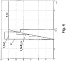
- FIG. 4 an exemplary course of the values of the variables is shown, the setpoint limitation taking effect when the reference variable jumps.
- the limited setpoint runs exactly so that the actual value reaches this after a sampling raster.
- the control deviation of the controller SR remains zero during the entire tracking and the integrator of the regulator SR does not change its value. This prevents the overshooting of the actual value.
- the controller is preferably executable as a time-discrete dead-beat controller.
- the controller is designed such that it can already compensate for the control deviation in a time step. This succeeds at least when the controller has a transfer function of the Z-transformed form 1 / (z * G (z)), where G is the transfer function of the controlled system.
Landscapes
- Engineering & Computer Science (AREA)
- Power Engineering (AREA)
- Control Of Ac Motors In General (AREA)
- Control Of Electric Motors In General (AREA)
Applications Claiming Priority (3)
| Application Number | Priority Date | Filing Date | Title |
|---|---|---|---|
| DE102006036170 | 2006-08-01 | ||
| DE102007027827.8A DE102007027827B4 (de) | 2006-08-01 | 2007-06-13 | Antrieb und Verfahren |
| PCT/EP2007/006318 WO2008014881A1 (de) | 2006-08-01 | 2007-07-17 | Antrieb und verfahren |
Publications (2)
| Publication Number | Publication Date |
|---|---|
| EP2050187A1 EP2050187A1 (de) | 2009-04-22 |
| EP2050187B1 true EP2050187B1 (de) | 2018-05-30 |
Family
ID=38860111
Family Applications (1)
| Application Number | Title | Priority Date | Filing Date |
|---|---|---|---|
| EP07786118.5A Active EP2050187B1 (de) | 2006-08-01 | 2007-07-17 | Antrieb und verfahren |
Country Status (6)
| Country | Link |
|---|---|
| US (1) | US8125178B2 (enExample) |
| EP (1) | EP2050187B1 (enExample) |
| JP (1) | JP5292637B2 (enExample) |
| CN (1) | CN101496275B (enExample) |
| DE (1) | DE102007027827B4 (enExample) |
| WO (1) | WO2008014881A1 (enExample) |
Families Citing this family (5)
| Publication number | Priority date | Publication date | Assignee | Title |
|---|---|---|---|---|
| DE102007014728A1 (de) * | 2007-03-24 | 2008-10-02 | Woodward Seg Gmbh & Co. Kg | Verfahren und Vorrichtung zum Betrieb einer doppeltgespeisten Asynchronmaschine bei transienten Netzspannungsänderungen |
| FR2916585B1 (fr) * | 2007-05-25 | 2009-08-21 | Alstom Transport Sa | Procede de regulation d'une tension ou d'un courant d'un filtre rlc, support d'enregistrement et vehicules pour ce procede. |
| FR3009630B1 (fr) * | 2013-08-09 | 2016-11-25 | Snecma | Procede et module de filtrage d'une consigne brute |
| US9910410B2 (en) * | 2014-02-11 | 2018-03-06 | Sabic Global Technologies B.V. | Multi-input multi-output control system and methods of making thereof |
| CN111740675B (zh) * | 2020-07-02 | 2022-07-19 | 合肥工业大学 | 永磁同步电机离散域电流环强鲁棒性二自由度控制方法 |
Family Cites Families (24)
| Publication number | Priority date | Publication date | Assignee | Title |
|---|---|---|---|---|
| DE199752C (enExample) | ||||
| DE1941312B2 (de) * | 1969-08-14 | 1972-11-23 | Siemens AG, 1000 Berlin u. 8000 München | Verfahren und einrichtung zur steuerung von asynchronmaschinen |
| DE2144422C2 (de) * | 1971-09-04 | 1973-09-20 | Siemens Ag | Einrichtung zum Steuern oder Regeln einer Asynchronmaschine |
| US4585985A (en) * | 1984-08-09 | 1986-04-29 | General Electric Company | Method of real time operating point identification and pole adjustment for an induction motor drive system |
| DE3438504A1 (de) * | 1984-10-20 | 1986-04-24 | Brown, Boveri & Cie Ag, 6800 Mannheim | Verfahren und einrichtung zur regelung einer drehfeldmaschine |
| US4808903A (en) * | 1987-04-13 | 1989-02-28 | Hitachi, Ltd. | Vector control system for induction motors |
| DE3850207T2 (de) * | 1987-09-29 | 1995-02-16 | Toshiba Kawasaki Kk | Regelvorrichtung für eine Induktionsmaschine. |
| DE4310778C2 (de) * | 1993-03-26 | 1995-02-09 | Licentia Gmbh | Verfahren zur zeitdiskreten Regelung des Stromes eines über einen Wechselrichter gespeisten Asynchronmotors |
| JP3235331B2 (ja) * | 1994-03-11 | 2001-12-04 | 富士電機株式会社 | 電流制御回路 |
| FI97654C (fi) * | 1994-09-09 | 1997-01-27 | Abb Industry Oy | Menetelmä epätahtikoneen käynnistämiseksi |
| DE19614866A1 (de) * | 1996-04-16 | 1997-10-23 | Zahnradfabrik Friedrichshafen | Verfahren zur Stromregelung |
| JPH10229687A (ja) * | 1997-02-14 | 1998-08-25 | Fuji Electric Co Ltd | 誘導電動機の可変速制御装置 |
| JPH11206199A (ja) * | 1998-01-20 | 1999-07-30 | Meidensha Corp | 誘導電動機の制御装置 |
| US7103425B1 (en) * | 1999-01-08 | 2006-09-05 | Lexmark International, Inc. | Method of regulating a target system using a frequency comparison of feedback and reference pulse trains |
| JP3611738B2 (ja) * | 1999-03-12 | 2005-01-19 | 株式会社三協精機製作所 | 電流制御装置 |
| DE19919752C5 (de) * | 1999-04-29 | 2010-12-16 | Sew-Eurodrive Gmbh & Co. Kg | Verfahren zum Zuschalten eines Umrichters an einen Asynchronmotor |
| JP3520002B2 (ja) * | 1999-12-08 | 2004-04-19 | 三菱電機株式会社 | 誘導電動機のベクトル制御装置 |
| US6359416B1 (en) * | 2000-09-29 | 2002-03-19 | Rockwell Automation Technologies, Inc. | Adaptive predictive synchronous current frame regulator method and apparatus |
| DK200200572A (da) * | 2002-04-17 | 2003-10-18 | Danfoss Drives As | Fremgangsmåde til måling af strøm i en motorstyring og motorstyring som bruger denne fremgangsmåde |
| DE10228824A1 (de) * | 2002-06-27 | 2004-05-19 | Siemens Ag | Verfahren und Vorrichtung zur Ermittlung eines Durchgehens eines drehzahlgeregelten, permanenterregten Synchronmotors |
| DE10336068B4 (de) | 2003-08-06 | 2006-04-06 | Siemens Ag | Verfahren zur gesteuerten Einprägung eines Ständerstrom- und eines Drehmoment-Sollwertes für eine stromrichtergespeiste Drehfeldmaschine |
| EP1513371B1 (en) * | 2004-10-19 | 2012-08-15 | Phonak Ag | Method for operating a hearing device as well as a hearing device |
| FR2884658B1 (fr) * | 2005-04-13 | 2007-05-18 | Schneider Toshiba Inverter | Procede d'ajustement de parametres d'un moteur electrique et variateur de vitesse utilisant un tel procede |
| EP1777806A2 (en) * | 2005-10-21 | 2007-04-25 | NSK Ltd. | Motor drive control apparatus and electric power steering apparatus |
-
2007
- 2007-06-13 DE DE102007027827.8A patent/DE102007027827B4/de active Active
- 2007-07-17 WO PCT/EP2007/006318 patent/WO2008014881A1/de not_active Ceased
- 2007-07-17 JP JP2009522131A patent/JP5292637B2/ja active Active
- 2007-07-17 EP EP07786118.5A patent/EP2050187B1/de active Active
- 2007-07-17 US US12/376,117 patent/US8125178B2/en active Active
- 2007-07-17 CN CN2007800278636A patent/CN101496275B/zh active Active
Non-Patent Citations (1)
| Title |
|---|
| None * |
Also Published As
| Publication number | Publication date |
|---|---|
| CN101496275B (zh) | 2012-12-19 |
| US8125178B2 (en) | 2012-02-28 |
| WO2008014881A1 (de) | 2008-02-07 |
| JP5292637B2 (ja) | 2013-09-18 |
| CN101496275A (zh) | 2009-07-29 |
| EP2050187A1 (de) | 2009-04-22 |
| DE102007027827B4 (de) | 2016-02-11 |
| DE102007027827A1 (de) | 2008-02-07 |
| JP2009545938A (ja) | 2009-12-24 |
| US20100007304A1 (en) | 2010-01-14 |
Similar Documents
| Publication | Publication Date | Title |
|---|---|---|
| DE19724946B4 (de) | Verfahren und Vorrichtung zur Drehzahlregelung einer geberlosen, feldorientiert betriebenen Asynchronmaschine | |
| EP0840441B1 (de) | Feldorientierte Regelung einer Drehfeldmaschine an der Spannungsdecke | |
| DE102008013799A1 (de) | Verfahren und System zur Steuerung von Permanentmagnet-AC-Maschinen | |
| EP2027648A1 (de) | Strombegrenzung für eine doppeltgespeiste asynchronmaschine | |
| EP2050187B1 (de) | Antrieb und verfahren | |
| DE112014007197T5 (de) | Antriebs-steuerungsvorrichtung für einen mehrwicklungsmotor | |
| WO1999022276A1 (de) | Verfahren zur einstellung der reglerparameter eines zustandsreglers | |
| DE112019007940T5 (de) | Motortreiber | |
| EP0633653B1 (de) | Stromregelverfahren und Vorrichtung für einen spannungseinprägenden Umrichter | |
| DE102012205371A1 (de) | Reglerstruktur und Verfahren zur feldorientierten Regelung einer Drehfeldmaschine bei Feldschwächung | |
| EP2619900B1 (de) | Verfahren zur (kupfer-)verlustoptimalen regelung einer asynchronmaschine mit einem umrichter | |
| DE102010021488A1 (de) | Verfahren zur (kupfer-)verlustoptimalen Regelung einer Asynchronmaschine mit einem Frequenzumrichter | |
| EP0771067A1 (de) | Verfahren und Vorrichtung zur feldorientierten Regelung einer Drehfeldmaschine | |
| EP2626998B1 (de) | Stromregelung für eine elektrische Maschine und zugehöriges Regelverfahren | |
| EP2050186B1 (de) | Antrieb und verfahren | |
| DE102023203654A1 (de) | Regelung des Statorstroms oder des verketteten Statorflusses für den Betrieb einer permanentmagneterregten Synchronmaschine sowie Verfahren | |
| DE102023101155B4 (de) | Vektorsteuerverfahren für eine Synchronmaschine und Steuereinheit | |
| DE102007033653B4 (de) | Anlage mit zwei lagesynchron geregelten Antrieben und Verfahren | |
| DE102008001311A1 (de) | Verfahren und Vorrichtung zum Betrieb eines Reglers, insbesondere zur Regelung einer Brennkraftmaschine | |
| DE2914732C2 (de) | Verfahren zur strukturoptimalen Regleranpassung stochastisch gestörter elektrischer Regelkreise | |
| DE102007009368B4 (de) | Verfahren zum Regeln einer Position und Antrieb zum Bewegen eines Objektes | |
| DE102004019518A1 (de) | Verfahren und Vorrichtung zur optimierten Regelung von Oberschwingungen | |
| DE102016213656B4 (de) | Vorrichtung zum Regeln der Drehzahl eines elektrischen Antriebs | |
| DE102016220132A1 (de) | Verfahren und Vorrichtung zur Drehzahlregelung einer Asynchronmaschine | |
| EP4326977A1 (de) | Regeleinrichtung zur regelung einer eine brennkraftmaschine und einen mit der brennkraftmaschine antriebswirkverbundenen generator umfassenden leistungsanordnung, regelanordnung mit einer solchen regeleinrichtung, leistungsanordnung und verfahren zur regelung einer leistungsanordnung |
Legal Events
| Date | Code | Title | Description |
|---|---|---|---|
| PUAI | Public reference made under article 153(3) epc to a published international application that has entered the european phase |
Free format text: ORIGINAL CODE: 0009012 |
|
| 17P | Request for examination filed |
Effective date: 20090302 |
|
| AK | Designated contracting states |
Kind code of ref document: A1 Designated state(s): AT BE BG CH CY CZ DE DK EE ES FI FR GB GR HU IE IS IT LI LT LU LV MC MT NL PL PT RO SE SI SK TR |
|
| AX | Request for extension of the european patent |
Extension state: AL BA HR MK RS |
|
| DAX | Request for extension of the european patent (deleted) | ||
| 17Q | First examination report despatched |
Effective date: 20161212 |
|
| GRAP | Despatch of communication of intention to grant a patent |
Free format text: ORIGINAL CODE: EPIDOSNIGR1 |
|
| INTG | Intention to grant announced |
Effective date: 20180118 |
|
| GRAS | Grant fee paid |
Free format text: ORIGINAL CODE: EPIDOSNIGR3 |
|
| GRAA | (expected) grant |
Free format text: ORIGINAL CODE: 0009210 |
|
| AK | Designated contracting states |
Kind code of ref document: B1 Designated state(s): AT BE BG CH CY CZ DE DK EE ES FI FR GB GR HU IE IS IT LI LT LU LV MC MT NL PL PT RO SE SI SK TR |
|
| REG | Reference to a national code |
Ref country code: GB Ref legal event code: FG4D Free format text: NOT ENGLISH |
|
| REG | Reference to a national code |
Ref country code: CH Ref legal event code: EP |
|
| REG | Reference to a national code |
Ref country code: FR Ref legal event code: PLFP Year of fee payment: 12 |
|
| REG | Reference to a national code |
Ref country code: CH Ref legal event code: NV Representative=s name: HEPP WENGER RYFFEL AG, CH Ref country code: AT Ref legal event code: REF Ref document number: 1004631 Country of ref document: AT Kind code of ref document: T Effective date: 20180615 |
|
| REG | Reference to a national code |
Ref country code: DE Ref legal event code: R096 Ref document number: 502007016208 Country of ref document: DE |
|
| REG | Reference to a national code |
Ref country code: IE Ref legal event code: FG4D Free format text: LANGUAGE OF EP DOCUMENT: GERMAN |
|
| REG | Reference to a national code |
Ref country code: NL Ref legal event code: FP |
|
| REG | Reference to a national code |
Ref country code: SE Ref legal event code: TRGR |
|
| REG | Reference to a national code |
Ref country code: LT Ref legal event code: MG4D |
|
| PG25 | Lapsed in a contracting state [announced via postgrant information from national office to epo] |
Ref country code: CY Free format text: LAPSE BECAUSE OF FAILURE TO SUBMIT A TRANSLATION OF THE DESCRIPTION OR TO PAY THE FEE WITHIN THE PRESCRIBED TIME-LIMIT Effective date: 20180530 Ref country code: ES Free format text: LAPSE BECAUSE OF FAILURE TO SUBMIT A TRANSLATION OF THE DESCRIPTION OR TO PAY THE FEE WITHIN THE PRESCRIBED TIME-LIMIT Effective date: 20180530 Ref country code: LT Free format text: LAPSE BECAUSE OF FAILURE TO SUBMIT A TRANSLATION OF THE DESCRIPTION OR TO PAY THE FEE WITHIN THE PRESCRIBED TIME-LIMIT Effective date: 20180530 Ref country code: BG Free format text: LAPSE BECAUSE OF FAILURE TO SUBMIT A TRANSLATION OF THE DESCRIPTION OR TO PAY THE FEE WITHIN THE PRESCRIBED TIME-LIMIT Effective date: 20180830 |
|
| PG25 | Lapsed in a contracting state [announced via postgrant information from national office to epo] |
Ref country code: GR Free format text: LAPSE BECAUSE OF FAILURE TO SUBMIT A TRANSLATION OF THE DESCRIPTION OR TO PAY THE FEE WITHIN THE PRESCRIBED TIME-LIMIT Effective date: 20180831 Ref country code: LV Free format text: LAPSE BECAUSE OF FAILURE TO SUBMIT A TRANSLATION OF THE DESCRIPTION OR TO PAY THE FEE WITHIN THE PRESCRIBED TIME-LIMIT Effective date: 20180530 |
|
| PG25 | Lapsed in a contracting state [announced via postgrant information from national office to epo] |
Ref country code: PL Free format text: LAPSE BECAUSE OF FAILURE TO SUBMIT A TRANSLATION OF THE DESCRIPTION OR TO PAY THE FEE WITHIN THE PRESCRIBED TIME-LIMIT Effective date: 20180530 Ref country code: SK Free format text: LAPSE BECAUSE OF FAILURE TO SUBMIT A TRANSLATION OF THE DESCRIPTION OR TO PAY THE FEE WITHIN THE PRESCRIBED TIME-LIMIT Effective date: 20180530 Ref country code: CZ Free format text: LAPSE BECAUSE OF FAILURE TO SUBMIT A TRANSLATION OF THE DESCRIPTION OR TO PAY THE FEE WITHIN THE PRESCRIBED TIME-LIMIT Effective date: 20180530 Ref country code: DK Free format text: LAPSE BECAUSE OF FAILURE TO SUBMIT A TRANSLATION OF THE DESCRIPTION OR TO PAY THE FEE WITHIN THE PRESCRIBED TIME-LIMIT Effective date: 20180530 Ref country code: RO Free format text: LAPSE BECAUSE OF FAILURE TO SUBMIT A TRANSLATION OF THE DESCRIPTION OR TO PAY THE FEE WITHIN THE PRESCRIBED TIME-LIMIT Effective date: 20180530 Ref country code: EE Free format text: LAPSE BECAUSE OF FAILURE TO SUBMIT A TRANSLATION OF THE DESCRIPTION OR TO PAY THE FEE WITHIN THE PRESCRIBED TIME-LIMIT Effective date: 20180530 |
|
| REG | Reference to a national code |
Ref country code: DE Ref legal event code: R097 Ref document number: 502007016208 Country of ref document: DE |
|
| PG25 | Lapsed in a contracting state [announced via postgrant information from national office to epo] |
Ref country code: LU Free format text: LAPSE BECAUSE OF NON-PAYMENT OF DUE FEES Effective date: 20180717 Ref country code: MC Free format text: LAPSE BECAUSE OF FAILURE TO SUBMIT A TRANSLATION OF THE DESCRIPTION OR TO PAY THE FEE WITHIN THE PRESCRIBED TIME-LIMIT Effective date: 20180530 |
|
| REG | Reference to a national code |
Ref country code: BE Ref legal event code: MM Effective date: 20180731 |
|
| PLBE | No opposition filed within time limit |
Free format text: ORIGINAL CODE: 0009261 |
|
| STAA | Information on the status of an ep patent application or granted ep patent |
Free format text: STATUS: NO OPPOSITION FILED WITHIN TIME LIMIT |
|
| REG | Reference to a national code |
Ref country code: IE Ref legal event code: MM4A |
|
| PG25 | Lapsed in a contracting state [announced via postgrant information from national office to epo] |
Ref country code: IE Free format text: LAPSE BECAUSE OF NON-PAYMENT OF DUE FEES Effective date: 20180717 |
|
| 26N | No opposition filed |
Effective date: 20190301 |
|
| PG25 | Lapsed in a contracting state [announced via postgrant information from national office to epo] |
Ref country code: BE Free format text: LAPSE BECAUSE OF NON-PAYMENT OF DUE FEES Effective date: 20180731 Ref country code: SI Free format text: LAPSE BECAUSE OF FAILURE TO SUBMIT A TRANSLATION OF THE DESCRIPTION OR TO PAY THE FEE WITHIN THE PRESCRIBED TIME-LIMIT Effective date: 20180530 |
|
| PG25 | Lapsed in a contracting state [announced via postgrant information from national office to epo] |
Ref country code: MT Free format text: LAPSE BECAUSE OF FAILURE TO SUBMIT A TRANSLATION OF THE DESCRIPTION OR TO PAY THE FEE WITHIN THE PRESCRIBED TIME-LIMIT Effective date: 20180530 |
|
| PG25 | Lapsed in a contracting state [announced via postgrant information from national office to epo] |
Ref country code: TR Free format text: LAPSE BECAUSE OF FAILURE TO SUBMIT A TRANSLATION OF THE DESCRIPTION OR TO PAY THE FEE WITHIN THE PRESCRIBED TIME-LIMIT Effective date: 20180530 |
|
| PG25 | Lapsed in a contracting state [announced via postgrant information from national office to epo] |
Ref country code: HU Free format text: LAPSE BECAUSE OF FAILURE TO SUBMIT A TRANSLATION OF THE DESCRIPTION OR TO PAY THE FEE WITHIN THE PRESCRIBED TIME-LIMIT; INVALID AB INITIO Effective date: 20070717 Ref country code: PT Free format text: LAPSE BECAUSE OF FAILURE TO SUBMIT A TRANSLATION OF THE DESCRIPTION OR TO PAY THE FEE WITHIN THE PRESCRIBED TIME-LIMIT Effective date: 20180530 |
|
| PG25 | Lapsed in a contracting state [announced via postgrant information from national office to epo] |
Ref country code: IS Free format text: LAPSE BECAUSE OF FAILURE TO SUBMIT A TRANSLATION OF THE DESCRIPTION OR TO PAY THE FEE WITHIN THE PRESCRIBED TIME-LIMIT Effective date: 20180930 |
|
| PGFP | Annual fee paid to national office [announced via postgrant information from national office to epo] |
Ref country code: GB Payment date: 20250529 Year of fee payment: 19 |
|
| PGFP | Annual fee paid to national office [announced via postgrant information from national office to epo] |
Ref country code: NL Payment date: 20250613 Year of fee payment: 19 |
|
| PGFP | Annual fee paid to national office [announced via postgrant information from national office to epo] |
Ref country code: FR Payment date: 20250610 Year of fee payment: 19 |
|
| PGFP | Annual fee paid to national office [announced via postgrant information from national office to epo] |
Ref country code: SE Payment date: 20250610 Year of fee payment: 19 |
|
| PGFP | Annual fee paid to national office [announced via postgrant information from national office to epo] |
Ref country code: FI Payment date: 20250715 Year of fee payment: 19 |
|
| PGFP | Annual fee paid to national office [announced via postgrant information from national office to epo] |
Ref country code: DE Payment date: 20250731 Year of fee payment: 19 |
|
| PGFP | Annual fee paid to national office [announced via postgrant information from national office to epo] |
Ref country code: IT Payment date: 20250623 Year of fee payment: 19 |
|
| PGFP | Annual fee paid to national office [announced via postgrant information from national office to epo] |
Ref country code: AT Payment date: 20250709 Year of fee payment: 19 |
|
| PGFP | Annual fee paid to national office [announced via postgrant information from national office to epo] |
Ref country code: CH Payment date: 20250801 Year of fee payment: 19 |