EP2048104A1 - Dispositif d'ascenseur - Google Patents
Dispositif d'ascenseur Download PDFInfo
- Publication number
- EP2048104A1 EP2048104A1 EP06781799A EP06781799A EP2048104A1 EP 2048104 A1 EP2048104 A1 EP 2048104A1 EP 06781799 A EP06781799 A EP 06781799A EP 06781799 A EP06781799 A EP 06781799A EP 2048104 A1 EP2048104 A1 EP 2048104A1
- Authority
- EP
- European Patent Office
- Prior art keywords
- brake
- car
- deceleration
- control portion
- calculation
- Prior art date
- Legal status (The legal status is an assumption and is not a legal conclusion. Google has not performed a legal analysis and makes no representation as to the accuracy of the status listed.)
- Granted
Links
Images


Classifications
-
- B—PERFORMING OPERATIONS; TRANSPORTING
- B66—HOISTING; LIFTING; HAULING
- B66B—ELEVATORS; ESCALATORS OR MOVING WALKWAYS
- B66B1/00—Control systems of elevators in general
- B66B1/24—Control systems with regulation, i.e. with retroactive action, for influencing travelling speed, acceleration, or deceleration
- B66B1/28—Control systems with regulation, i.e. with retroactive action, for influencing travelling speed, acceleration, or deceleration electrical
- B66B1/32—Control systems with regulation, i.e. with retroactive action, for influencing travelling speed, acceleration, or deceleration electrical effective on braking devices, e.g. acting on electrically controlled brakes
-
- B—PERFORMING OPERATIONS; TRANSPORTING
- B66—HOISTING; LIFTING; HAULING
- B66B—ELEVATORS; ESCALATORS OR MOVING WALKWAYS
- B66B5/00—Applications of checking, fault-correcting, or safety devices in elevators
- B66B5/02—Applications of checking, fault-correcting, or safety devices in elevators responsive to abnormal operating conditions
Definitions
- the present invention relates to an elevator apparatus having a brake control device capable of controlling a degree of deceleration of a car at a time of emergency braking.
- the braking force of an electromagnetic brake is controlled at the time of emergency braking such that the degree of deceleration of a car becomes equal to a predetermined value, based on a deceleration command value and a speed signal (e.g., see Patent Document 1).
- Patent Document 1 JP 07-157211 A
- both a basic operation of emergency braking and an operation of controlling the braking force are performed by a single brake control unit. Therefore, when the degree of deceleration of the car becomes excessively high due to a malfunction in the brake control unit or the like, passengers feel uncomfortable. On the contrary, when the degree of deceleration of the car becomes excessively low due to a malfunction in the brake control unit or the like, the braking distance of the car becomes longer.
- the present invention has been made to solve the above-mentionedproblems, and it is therefore an obj ect of the present invention to obtain an elevator apparatus that makes it possible to stop a car more positively even in the event of a malfunction in a deceleration control portion while suppressing the degree of deceleration of the car at the time of emergency braking.
- An elevator apparatus includes: a hoisting machine having a drive sheave, a motor for rotating the drive sheave, and a brake device for braking rotation of the drive sheave; suspension means looped around the drive sheave; a car suspended by the suspension means to be raised/lowered by the hoisting machine; and a brake control device for controlling the brake device, in which: the brake control device has a first brake control portion for operating the brake device upon detection of an abnormality to stop the car as an emergency measure, and a second brake control portion for reducing a braking force of the brake device when a degree of deceleration of the car becomes equal to or higher than a predetermined value at a time of emergency braking operation of the first brake control portion; and the second brake control portion detects emergency braking operation of the brake device independently of the first brake control portion.
- FIG. 1 is a schematic diagram showing an elevator apparatus according to Embodiment 1 of the present invention.
- the hoisting machine 4 has a drive sheave 5 around which the main rope 3 is looped, a motor 6 for rotating the drive sheave 5, and braking means 7 for braking rotation of the drive sheave 5.
- the braking means 7 has a brake pulley 8 that is rotated integrally with the drive sheave 5, and a brake device 9 for braking rotation of the brake pulley 8.
- the drive sheave 5, the motor 6, and the brake pulley 8 are provided coaxially.
- the brake device 9 has a brake shoe that is moved into contact with and away from the brake pulley 8, a brake spring for pressing the brake shoe against the brake pulley 8, and an electromagnet for opening the brake shoe away from the brake pulley 8 against the brake spring.
- the motor 6 is provided with a speed detector 10 for generating a signal corresponding to a rotational speed of a rotary shaft of the motor 6, that is, a rotational speed of the drive sheave 5.
- a speed detector 10 for generating a signal corresponding to a rotational speed of a rotary shaft of the motor 6, that is, a rotational speed of the drive sheave 5.
- the speed detector 10 is, for example, an encoder or a resolver.
- a signal from the speed detector 10 is input to a brake control device 11.
- the brake control device 11 controls the brake device 9.
- a deflector pulley 12 is disposed in the vicinity of the drive sheave 5.
- FIG. 2 is a circuit diagram showing the brake control device 11 of FIG. 1 partially in the form of blocks.
- the brake control device 11 has a first brake control portion 13 and a second brake control portion 14 that control the brake device 9 independently of each other.
- the electromagnet of the brake device 9 is provided with a brake coil (electromagnetic coil) 15.
- a brake coil electromagnet
- the electromagnet is excited to generate an electromagnetic force for canceling a braking force of the brake device 9, so the brake shoe is opened away from the brake pulley 8.
- the degree of the opening of the brake device 9 can be controlled.
- a circuit in which a discharge resistor 16 and a first discharge diode 17 are connected in series is connected in parallel to the brake coil 15.
- a second discharge diode 20 is connected in parallel to the brake coil 15 at both ends thereof via a first electromagnetic relay 18 and a second electromagnetic relay 19, respectively.
- the brake coil 15 is connected on the first electromagnetic relay 18 side thereof to a power supply 21.
- the brake coil 15 is connected on the second electromagnetic relay 19 side thereof to a ground 23 of the power supply 21 via a brake switch 22.
- a semiconductor switch is employed as the brake switch 22.
- the turning ON/OFF of the brake switch 22 is controlled by a brake determination portion 24.
- the brake determination portion 24 turns the brake switch 22 ON to energize the brake coil 15, thereby canceling the braking force of the brake device 9.
- the brake determination portion 24 turns the brake switch 22 OFF to deenergize the brake coil 15, thereby causing the brake device 9 to generate a braking force (to hold car 1 stationary).
- the brake determination portion 24 turns the brake switch 22 OFF and opens the electromagnetic relays 18 and 19, thereby deenergizing the brake coil 15 and causing the brake device 9 to perform braking operation.
- the car 1 is stopped as an emergency measure.
- the electromagnetic relays 18 and 19 are opened, the discharge resistor 16 and the first discharge diode 17 swiftly reduce the induction current flowing through the brake coil 15 to precipitate generation of a braking force.
- the function of the brake determination portion 24 is realized by, for example, a first microcomputer (not shown) provided in an elevator control device for controlling the traveling of the car 1. That is, a program for realizing the function of the brake determination portion 24 is stored in the first microcomputer.
- the first brake control portion (main control portion) 13 has the electromagnetic relays 18 and 19, the second discharge diode 20, the brake switch 22, and the brake determination portion 24.
- the first brake control portion 13 also includes a safety circuit (not shown) for opening the electromagnetic relays 18 and 19 in response to an abnormality in the elevator apparatus.
- the current flowing through the brake coil 15 is detected by a first current detector 25 and a second current detector 26.
- the speed detector 10 is provided with a first encoder 27 and a second encoder 28, which are each designed as a speed sensor for generating a signal corresponding to a rotational speed of the motor 6.
- An endpoint node between the brake coil 15 and the first electromagnetic relay 18 is connected to a power supply 30 via a circuit in which a third electromagnetic relay 29a and a fourth electromagnetic relay 29b are connected in series.
- An endpoint node between the brake coil 15 and the second electromagnetic relay 19 is connected to a ground 34 of the power supply 30 via a circuit in which a fifth electromagnetic relay 31a, a sixth electromagnetic relay 31b, a first deceleration control switch 32, and a second deceleration control switch 33 are connected in series.
- a third discharge diode 35 is connected in parallel to a circuit in which the third electromagnetic relay 29a, the fourth electromagnetic relay 29b, the brake coil 15, the fifth electromagnetic relay 31a, and the sixth electromagnetic relay 31b are connected in series.
- the first deceleration control switch 32 and the second deceleration control switch 33 each serve to control the degree of deceleration of the car 1 at the time of emergency braking of the car 1.
- Semiconductor switches are employed as the deceleration control switches 32 and 33.
- the deceleration control performed by the first deceleration control switch 32 and the second deceleration control switch 33 is validated when all the electromagnetic relays 29a, 29b, 31a, and 31b are closed, and is invalidated when one of the electromagnetic relays 29a, 29b, 31a, and 31b is open.
- the turning ON/OFF of the first deceleration control switch 32 is controlled by a first calculation portion 36.
- the turning ON/OFF of the second deceleration control switch 33 is controlled by a second calculation portion 37.
- the first calculation portion 36 is constituted by a second microcomputer.
- the second calculation portion 37 is constituted by a third microcomputer.
- a two-port RAM 38 is connected between the first calculation portion 36 and the second calculation portion 37.
- a deceleration control determination portion 39 has the first calculation portion 36, the second calculation portion 37, and the two-port RAM 38.
- Signals from the first current detector 25 and the second current detector 26 and signals from the first encoder 27 and the second encoder 28 are input to the first calculation portion 36.
- the signals from the first current detector 25 and the second current detector 26 and the signals from the first encoder 27 and the second encoder 28 are also input to the second calculation portion 37.
- the first calculation portion 36 calculates a position y [m] of the car 1, a speed V [m/s] of the car 1, and a deceleration ⁇ [m/s 2 ] of the car 1 based on the signals from the first encoder 27 and the second encoder 28.
- the first calculation portion 36 controls the turning ON/OFF of the first deceleration control switch 32 based on the speed of the car 1, the degree of deceleration of the car 1, and the current value of the brake coil 15.
- the second calculation portion 37 calculates a position y [m] of the car 1, a speed V [m/s] of the car 1, and a deceleration ⁇ [m/s 2 ] of the car 1 independently of the first calculation portion 36, based on the signals from the first encoder 27 and the second encoder 28.
- the second calculation portion 37 controls the turning ON/OFF of the second deceleration control switch 33 based on the speed of the car 1, the degree of deceleration of the car 1, and the current value of the brake coil 15.
- the third electromagnetic relay 29a and the fifth electromagnetic relay 31a are opened/closed by a first drive coil 40a.
- the first drive coil 40a is connected to a power supply 41 and a ground 42.
- a first drive coil control switch 43 for turning ON/OFF the supply of a current to the first drive coil 40a is connected between the first drive coil 40a and the ground 42.
- a semiconductor switch is employed as the first drive coil control switch 43. The turning ON/OFF of the first drive coil control switch 43 is controlled by the first calculation portion 36.
- the fourth electromagnetic relay 29b and the sixth electromagnetic relay 31b are opened/closed by a second drive coil 40b.
- the second drive coil 40b is connected to a power supply 44 and a ground 45.
- a second drive coil control switch 46 for turning ON/OFF the supply of a current to the second drive coil 40b is connected between the second drive coil 40b and the ground 45.
- a semiconductor switch is employed as the second drive coil control switch 46. The turning ON/OFF of the second drive coil control switch 46 is controlled by the second calculation portion 37.
- a seventh electromagnetic relay 47a that is opened/closed in accordance with the opening/closing of the third electromagnetic relay 29a, and an eighth electromagnetic relay 48a that is opened/closed in accordance with the opening/closing of the fifth electromagnetic relay 31a are connected in series between a power supply 49 and a ground 50 via a resistor 51.
- the first calculation portion 36 detects a voltage of the resistor 51 on the power supply 49 side. Thus, the first calculation portion 36 monitors the open/closed states of the third electromagnetic relay 29a and the fifth electromagnetic relay 31a.
- a ninth electromagnetic relay 47b that is opened/closed in accordance with the opening/closing of the fourth electromagnetic relay 29b, and a tenth electromagnetic relay 48b that is opened/closed in accordance with the opening/closing of the sixth electromagnetic relay 31b are connected in series between a power supply 52 and a ground 53 via a resistor 54.
- the second calculation portion 37 detects a voltage of the resistor 54 on the power supply 52 side.
- the second calculation portion 37 monitors the open/closed states of the fourth electromagnetic relay 29b and the sixth electromagnetic relay 31b.
- the first calculation portion 36 and the second calculation portion 37 make a comparison between a command for the drive coil control switch 43 and the open/closed states of the electromagnetic relays 29a and 31a and a comparison between a command for the drive coil control switch 46 and the open/closed states of the electromagnetic relays 29b and 31b, respectively, thereby determining whether or not a malfunction such as the adhesion of a contact or the like has occurred in each of the electromagnetic relays 29a, 29b, 31a, and 31b.
- the first calculation portion 36 compares a signal from the first current detector 25 with a signal from the second current detector 26 to determine whether or not a malfunction has occurred in the first current detector 25 and the second current detector 26.
- the first calculation portion 36 compares a signal from the first encoder 27 with a signal from the second encoder 28 to determine whether or not a malfunction has occurred in the first encoder 27 and the second encoder 28.
- the first calculation portion 36 receives a calculation result obtained by the second calculation portion 37 via the two-port RAM 38, and compares the received calculation result with a calculation result obtained by the first calculation portion 36, thereby determining whether or not a malfunction has occurred in the first calculation portion 36 and the second calculation portion 37.
- the second calculation portion 37 compares a signal from the first current detector 25 with a signal from the second current detector 26 to determine whether or not a malfunction has occurred in the first current detector 25 and the second current detector 26.
- the second calculation portion 37 compares a signal from the first encoder 27 with a signal from the second encoder 28 to determine whether or not a malfunction has occurred in the first encoder 27 and the second encoder 28.
- the second calculation portion 37 receives a calculation result obtained by the first calculation portion 36 via the two-port RAM 38, and compares the received calculation result with a calculation result obtained by the second calculation portion 37, thereby determining whether or not a malfunction has occurred in the first calculation portion 36 and the second calculation portion 37.
- each of the first calculation portion 36 and the second calculation portion 37 outputs a command to open corresponding ones of the electromagnetic relays 29a, 29b, 31a, and 31b, and outputs a malfunction detection signal to a malfunction reporting portion 55.
- the malfunction reporting portion 55 informs the elevator control device that some malfunction has occurred in the second brake control portion 14.
- the elevator control device stops the car 1 at, for example, the nearest floor, halts the traveling of the elevator apparatus, and causes the elevator apparatus to operate to report the occurrence of the malfunction to the outside.
- the second brake control portion (deceleration control portion) 14 has the electromagnetic relays 29a, 29b, 31a, 31b, 47a, 47b, 48a, and 48b, the deceleration control switches 32 and 33, the discharge diode 35, the deceleration control determination portion 39, the drive coils 40a and 40b, the drive coil control switches 43 and 46, the resistors 51 and 54, and the malfunction reporting portion 55.
- FIG. 3 is an explanatory diagram showing a current flowing through the brake coil 15 of FIG. 2 at the time of braking.
- FIG. 4 is an explanatory diagram showing a state in the case where the third electromagnetic relay 2 9a of FIG. 3 , the fourth electromagnetic relay 29b of FIG. 3 , the fifth electromagnetic relay 31a of FIG. 3 , and the sixth electromagnetic relay 31b of FIG. 3 are closed.
- FIG. 5 is a graph showing how the coil currents of FIGS. 3 and 4 change with time.
- each of the first calculation portion 36 and the second calculation portion 37 closes corresponding ones of the electromagnetic relays 29a, 29b, 31a, and 31b to apply the braking force gradually, with a view to preventing the degree of deceleration of the car 1 from becoming too high.
- each of the first calculation portion 36 and the second calculation portion 37 opens corresponding ones of the electromagnetic relays 29a, 29b, 31a, and 31b to apply the braking force immediately, with a view to decelerating the car 1 swiftly.
- the braking distance covered by the car 1 from the moment when emergency stop operation is started to the moment when the car 1 is stopped is shortened.
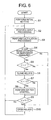
- FIG. 6 is a flowchart showing deceleration control operation of each of the first calculation portion 36 of FIG. 2 and the second calculation portion 37 of FIG. 2 .
- the first calculation portion 36 and the second calculation portion 37 perform the processings shown in FIG. 6 at the same time and in tandem with each other.
- the first calculation portion 36 and the second calculation portion 37 first perform initial settings of a plurality of parameters required for the processings (Step S1).
- a speed V0 [m/s] of the car 1 which is used to determine whether or not the car 1 is stopped a speed V1 [m/s] of the car 1 at which deceleration control is stopped, a threshold I0 [A] of the current value of the brake coil 15, a first threshold ⁇ 1 [m/s 2 ] of the degree of deceleration of the car 1, and a second threshold ⁇ 2 [m/s 2 ] of the degree of deceleration of the car 1 ( ⁇ 1 ⁇ ⁇ 2) are set as the parameters.
- each of the first calculation portion 36 and the second calculation portion 37 acquires signals from the first encoder 27 and the second encoder 28 and signals from the first current detector 25 and the second current detector 26 at predetermined period (Step S2). Then, the first calculation portion 36 and the second calculation portion 37 calculate the position y [m] of the car 1, the speed V [m/s] of the car 1, and the deceleration ⁇ [m/s 2 ] of the car 1 based on the signals from the first encoder 27 and the second encoder 28 (Step S3).
- the first calculation portion 36 and the second calculation portion 37 determine whether or not the car 1 is in emergency stop operation (Step S4). More specifically, when the speed of the car 1 (rotational speed of the motor) is higher than the speed V0 for determining whether or not the car 1 is stopped and the current value of the brake coil 15 is smaller than the current value I0 for determining whether or not the car 1 is stopped, the first calculation portion 36 and the second calculation portion 37 determine that the car 1 is in emergency stop operation. When the car 1 is not in emergency stop operation, the first calculation portion 36 and the second calculation portion 37 open all the electromagnetic relays 29a, 29b, 31a, and 31b (Step S10).
- the first calculation portion 36 and the second calculation portion 37 determine whether or not the deceleration ⁇ of the car 1 is higher than the first threshold ⁇ 1 (Step S5).
- the first calculation portion 36 and the second calculation portion 37 open all the electromagnetic relays 29a, 29b, 31a, and 31b (Step S10).
- ⁇ > ⁇ 1 the first calculation portion 36 and the second calculation portion 37 close all the electromagnetic relays 29a, 29b, 31a, and 31b (Step S6).
- the supply of a current to the motor 6 is also shut off. Therefore, the car 1 may be accelerated or decelerated due to an imbalance between a load on the car 1 side and a load of the counterweight 2 from a moment when an emergency stop command is issued to a moment when a braking force is actually applied.
- the first calculation portion 36 and the second calculation portion 37 determine that the car 1 is accelerated immediately after the issuance of the emergency stop command, and open the electromagnetic relays 29a, 29b, 31a, and 31b to apply the braking force swiftly.
- the first calculation portion 36 and the second calculation portion 37 determine that the car 1 is decelerated, and close the electromagnetic relays 29a, 29b, 31a, and 31b to perform deceleration control, with a view to preventing the degree of deceleration of the car 1 from becoming excessively high.
- the first calculation portion 36 and the second calculation portion 37 determine whether or not the deceleration ⁇ of the car 1 is higher than the second threshold ⁇ 2 (Step S7).
- the first calculation portion 36 and the second calculation portion 37 turn the deceleration control switches 32 and 33 ON/OFF with a preset switching duty (e.g., 50%) to suppress the deceleration ⁇ of the car 1 (Step S8).
- a preset switching duty e.g. 50%
- the first calculation portion 36 and the second calculation portion 37 hold the deceleration control switches 32 and 33 open. After that, the first calculation portion 36 and the second calculation portion 37 determine whether to stop control or not (Step S9). In determining whether to stop control or not, the first calculation portion 36 and the second calculation portion 37 determine whether or not the speed V of the car 1 is equal to or lower than a threshold V1. When V ⁇ V1, the first calculation portion 36 and the second calculation portion 37 directly return to an input processing (Step S2). When V ⁇ V1, the first calculation portion 36 and the second calculation portion 37 open all the electromagnetic relays 29a, 29b, 31a, and 31b (Step S10), and then return to the input processing (Step S2).
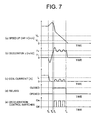
- FIG. 7 is an explanatory diagram showing how the speed of the car 1, the degree of deceleration of the car 1, the current of the brake coil 15, the states of the electromagnetic relays 29a, 29b, 31a, and 31b, and the states of the deceleration control switches 32 and 33 change with time in the case where the car 1 accelerates immediately after the issuance of an emergency stop command.
- the car 1 When the emergency stop command is issued, the car 1 is accelerated temporarily. After that, when a braking force is applied to the car 1, the car 1 is decelerated. Then, when the degree of deceleration of the car 1 reaches ⁇ 1 at a time instant T2, the electromagnetic relays 29a, 29b, 31a, and 31b are closed. When the degree of deceleration of the car 1 reaches ⁇ 2 at a time instant T3, the deceleration control switches 32 and 33 are turned ON/OFF. After that, when the speed of the car 1 becomes lower than V1, the electromagnetic relays 29a, 29b, 31a, and 31b are opened, so deceleration control performed by the deceleration control switches 32 and 33 is stopped.
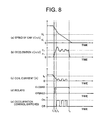
- FIG. 8 is an explanatory diagram showing how the speed of the car 1, the degree of deceleration of the car 1, the current of the brake coil 15, the states of the electromagnetic relays 29a, 29b, 31a, and 31b, and the states of the deceleration control switches 32 and 33 change with time in the case where the car 1 decelerates immediately after the issuance of an emergency stop command.
- the car 1 starts decelerating immediately. Then, when the degree of deceleration of the car 1 reaches ⁇ 1 at the time instant T2, the electromagnetic relays 29a, 29b, 31a, and 31b are closed. When the degree of deceleration of the car 1 reaches ⁇ 2 at the time instant T3, the deceleration control switches 32 and 33 are turned ON/OFF. After that, when the speed of the car 1 becomes lower than V1, the electromagnetic relays 29a, 29b, 31a, and 31b are opened, so deceleration control performed by the deceleration control switches 32 and 33 is stopped.
- FIG. 9 is a flowchart showing abnormality diagnosis operation of each of the first calculation portion 36 and the second calculation portion 37 of FIG. 2 .
- the first calculation portion 36 and the second calculation portion 37 call diagnosis processings shown in FIG. 9 as soon as the processings following the input processing (Step S2) of FIG. 6 are completed.
- the first calculation portion 36 and the second calculation portion 37 make a determination on the consistency of values input from the sensors and values calculated by the calculation portions 36 and 37 (Step S11). More specifically, when the difference between the input values and the difference between the calculated values are within each of predetermined ranges, the first calculation portion 36 and the second calculation portion 37 determine that there is no abnormality, and return to the subsequent processing shown in FIG. 6 . When the difference between the input values or the difference between the calculated values exceeds a corresponding one of the predetermined ranges, the first calculation portion 36 and the second calculation portion 37 determine that there is an abnormality, open the electromagnetic relays 29a, 29b, 31a, and 31b (Step S12), and output malfunction detection signals to the malfunction reporting portion 55 (Step S13).
- the brake control device 11 has the first brake control portion 13 and the second brake control portion 14, and the second brake control portion 14 detects emergency braking operation of the brake device 9 independently of the first brake control portion 13. Therefore, while the degree of deceleration of the car 1 at the time of emergency braking can be suppressed, the car 1 can be stopped more reliably even in the event of a malfunction in the second brake control portion 14 serving as the deceleration control portion.
- the second brake control portion 14 monitors the speed of the car 1 and the current of the brake coil 15 to detect that the brake device 9 has started emergency braking operation. Therefore, emergency braking operation of the brake device 9 can be detected with ease. In addition, when the speed of the car 1 is higher than the predetermined speed V0 and the current of the brake coil 15 is smaller than the predetermined value I0, the second brake control portion 14 determines that the brake device 9 is in emergency stop operation. Therefore, emergency braking operation can be detected more reliably.
- the second brake control portion 14 compares the signals from the first encoder 27 and the second encoder 28 with each other to detect a malfunction in at least one of the encoders 27 and 28, and compares the signals from the first current detector 25 and the second current detector 26 with each other to detect a malfunction in at least one of the current detectors 25 and 26. Therefore, enhancement of reliability can be achieved.
- the second brake control portion 14 invalidates deceleration control performed thereby, so the car 1 can be stopped more reliably even in the event of a malfunction in at least one of the sensors.
- the second brake control portion 14 has the first calculation portion 36 and the second calculation portion 37 that perform both the operation of determining whether or not the brake device 9 has started emergency braking operation and the operation of reducing the braking force of the brake device 9 independently of each other through the calculation processings. Therefore, enhancement of reliability can be achieved. Still further, the first calculation portion 36 and the second calculation portion 37 compare calculation results thereof with each other to detect the occurrence of a malfunction in at least one of the first calculation portion 36 and the second calculation portion 37. Therefore, further enhancement of reliability can be achieved. When a malfunction occurs in at least one of the first calculation portion 36 and the second calculation portion 37, the second brake control portion 14 invalidates deceleration control performed thereby. Therefore, the car 1 can be stopped more reliably even in the event of a malfunction in at least one of the calculation portions 36 and 37.
- the second brake control portion 14 can detect an abnormality in the operation of opening/closing the electromagnetic relays 29a, 29b, 31a, and 31b. Therefore, enhancement of reliability can be achieved. Still further, the second brake control portion 14 has the discharge diode 35 that is connected in parallel to the brake coil 15 by closing all the electromagnetic relays 29a, 29b, 31a, and 31b. Therefore, a back electromotive force generated as a result of an inductance of the brake coil 15 can be suppressed when the deceleration control switches 32 and 33 are repeatedly turned ON/OFF.
- the second brake control portion 14 validates the control of the degree of deceleration of the car 1 immediately, so the degree of deceleration of the car 1 can be prevented more reliably from becoming excessively high.
- the second brake control portion 14 validates the control of the degree of deceleration of the car 1 after the car 1 starts decelerating. Therefore, a braking force can be applied to the car 1 swiftly, and the braking distance of the car 1 can be prevented from becoming long.
- the encoders 27 and 28 provided on the motor 6 are exemplified as the speed sensors.
- the speed sensors may be provided at another location, for example, on a speed governor, as long as each of the speed sensors can generate a signal corresponding to a speed of the car 1.
- the determination on emergency stop is made from the speed of the car 1 and the current value of the brake coil 15.
- the determination on emergency stop may be made in consideration of a derivative value of the current value of the brake coil 15 as well as the aforementioned values.
- the current of the brake coil 15 is smaller than a predetermined value, and the derivative value of the current value of the brake coil 15 is negative, it is determined that the car 1 is being stopped as an emergency measure.
- the occurrence of erroneous detection resulting from vibrations within the car 1 in the process of stopping the car 1 can be avoided.
- the brake device 9 is provided on the hoisting machine 4.
- the brake device 9 may be provided at another location.
- the brake device may be a car brake mounted on the car, or a rope brake for gripping the main rope to brake the car.
Landscapes
- Engineering & Computer Science (AREA)
- Automation & Control Theory (AREA)
- Elevator Control (AREA)
- Maintenance And Inspection Apparatuses For Elevators (AREA)
- Regulating Braking Force (AREA)
Applications Claiming Priority (1)
| Application Number | Priority Date | Filing Date | Title |
|---|---|---|---|
| PCT/JP2006/314888 WO2008012896A1 (fr) | 2006-07-27 | 2006-07-27 | Dispositif d'ascenseur |
Publications (3)
| Publication Number | Publication Date |
|---|---|
| EP2048104A1 true EP2048104A1 (fr) | 2009-04-15 |
| EP2048104A4 EP2048104A4 (fr) | 2014-01-01 |
| EP2048104B1 EP2048104B1 (fr) | 2014-08-20 |
Family
ID=38981211
Family Applications (1)
| Application Number | Title | Priority Date | Filing Date |
|---|---|---|---|
| EP06781799.9A Expired - Fee Related EP2048104B1 (fr) | 2006-07-27 | 2006-07-27 | Dispositif d'ascenseur |
Country Status (6)
| Country | Link |
|---|---|
| US (1) | US7938231B2 (fr) |
| EP (1) | EP2048104B1 (fr) |
| JP (1) | JP4955556B2 (fr) |
| KR (1) | KR100973881B1 (fr) |
| CN (1) | CN101268003B (fr) |
| WO (1) | WO2008012896A1 (fr) |
Cited By (3)
| Publication number | Priority date | Publication date | Assignee | Title |
|---|---|---|---|---|
| EP2147883A4 (fr) * | 2007-05-24 | 2013-12-18 | Mitsubishi Electric Corp | Ascenseur |
| EP2246285A4 (fr) * | 2008-02-28 | 2014-07-16 | Mitsubishi Electric Corp | Système d'ascenseur |
| EP2407410A4 (fr) * | 2009-03-13 | 2017-10-18 | Mitsubishi Electric Corporation | Dispositif d'ascenseur |
Families Citing this family (41)
| Publication number | Priority date | Publication date | Assignee | Title |
|---|---|---|---|---|
| WO2007099633A1 (fr) * | 2006-03-02 | 2007-09-07 | Mitsubishi Denki Kabushiki Kaisha | Dispositif d'ascenseur |
| US7891466B2 (en) * | 2006-03-17 | 2011-02-22 | Mitsubishi Electric Corporation | Elevator apparatus for emergency braking |
| WO2008012896A1 (fr) * | 2006-07-27 | 2008-01-31 | Mitsubishi Electric Corporation | Dispositif d'ascenseur |
| US20100083429A1 (en) * | 2007-03-22 | 2010-04-08 | Carraro S.R.L. | Engineered textile yarn |
| US8167094B2 (en) * | 2007-04-26 | 2012-05-01 | Mitsubishi Electric Corporation | Elevator apparatus |
| WO2009013821A1 (fr) * | 2007-07-25 | 2009-01-29 | Mitsubishi Electric Corporation | Ascenseur |
| CN101903274B (zh) * | 2007-12-17 | 2013-10-02 | 三菱电机株式会社 | 电梯装置 |
| CN101910040B (zh) * | 2007-12-27 | 2013-08-21 | 三菱电机株式会社 | 电梯装置 |
| JP4508246B2 (ja) * | 2008-02-21 | 2010-07-21 | 株式会社デンソーウェーブ | ロボットの電磁ブレーキ制御装置およびロボットの電磁ブレーキの異常判定方法 |
| US8365872B2 (en) | 2008-04-15 | 2013-02-05 | Mitsubishi Electric Corporation | Elevator device having the plurality of hoisting machines |
| WO2009146717A1 (fr) * | 2008-06-03 | 2009-12-10 | Otis Elevator Company | Essai relatif à une seule mâchoire de frein (électrique) pour des ascenseurs |
| EP2287102B1 (fr) * | 2008-06-20 | 2016-07-20 | Mitsubishi Electric Corporation | Dispositif d'ascenseur |
| FI120986B (fi) * | 2008-11-03 | 2010-05-31 | Kone Corp | Järjestely ja menetelmä jarrun toiminnan valvomiseksi ja hissijärjestelmä |
| JPWO2011048664A1 (ja) * | 2009-10-20 | 2013-03-07 | 三菱電機株式会社 | エレベータの安全装置 |
| EP2502869B1 (fr) * | 2009-11-18 | 2017-01-25 | Mitsubishi Electric Corporation | Dispositif d'ascenseur |
| JP5360231B2 (ja) * | 2009-12-15 | 2013-12-04 | 三菱電機株式会社 | エレベータ装置 |
| US9637349B2 (en) | 2010-11-04 | 2017-05-02 | Otis Elevator Company | Elevator brake including coaxially aligned first and second brake members |
| EP2651808B1 (fr) * | 2010-12-17 | 2016-03-09 | Inventio AG | Appareil d'élévation à cabine et contrepoids |
| FI123238B (fi) * | 2011-02-02 | 2012-12-31 | Kone Corp | Menetelmä ja järjestely nostokoneiston jarrun jarrutusvoiman uudistamiseksi |
| WO2012105986A1 (fr) | 2011-02-04 | 2012-08-09 | Otis Elevator Company | Système permettant de séquencer l'arrêt d'un dispositif de freinage |
| BR112014002825B1 (pt) * | 2011-08-11 | 2021-04-20 | Inventio Ag | método de teste de uma instalação de elevadores e conjunto de monitoramento configurado para a realizar o método de teste |
| EP2763925B1 (fr) * | 2011-10-06 | 2020-11-25 | Otis Elevator Company | Commande de frein d'ascenseur |
| FI123348B (fi) * | 2011-10-07 | 2013-02-28 | Kone Corp | Hissin valvontajärjestely sekä menetelmä hissin valvomiseksi |
| WO2013088823A1 (fr) * | 2011-12-12 | 2013-06-20 | 三菱電機株式会社 | Dispositif de diagnostic de l'état d'un frein électromagnétique et procédé associé |
| FI123506B (fi) * | 2012-05-31 | 2013-06-14 | Kone Corp | Hissin käyttölaite sekä hissin turvajärjestely |
| EP2669233A1 (fr) * | 2012-05-31 | 2013-12-04 | Ziehl-Abegg AG | Circuit de commande de freinage pour un frein actionné de manière électromagnétique et module d'entraînement |
| CN102795524B (zh) * | 2012-07-27 | 2014-07-23 | 石家庄五龙制动器股份有限公司 | 电梯制动系统的abs制动控制电路 |
| CN102897627A (zh) * | 2012-10-30 | 2013-01-30 | 路文强 | 一种带有应急助推器的电梯 |
| CN102963784B (zh) * | 2012-11-28 | 2015-02-04 | 南京理工大学 | 电梯曳引机驱动、控制一体化系统的工作方法 |
| CN103663031A (zh) * | 2013-07-17 | 2014-03-26 | 太仓市鸿欣工业产品设计有限公司 | 电梯跌落急救装置 |
| CN103803366B (zh) | 2013-12-19 | 2016-04-27 | 西子奥的斯电梯有限公司 | 一种电梯抱闸力矩检测方法 |
| EP3006385B1 (fr) * | 2014-10-09 | 2017-05-31 | Kone Corporation | Dispositif de commande de frein et système d'ascenseur |
| WO2016085757A1 (fr) * | 2014-11-24 | 2016-06-02 | Otis Elevator Company | Système de frein électromagnétique |
| JP6393633B2 (ja) * | 2015-02-27 | 2018-09-19 | 株式会社日立製作所 | エレベーター |
| CN107922147B (zh) * | 2015-08-12 | 2019-11-19 | 因温特奥股份公司 | 用于电梯的防抱死制动装置以及用于对其进行控制的方法 |
| CN106081989A (zh) * | 2016-07-14 | 2016-11-09 | 杭州奥立达电梯有限公司 | 一种电梯抱闸检测装置及方法 |
| JP6452925B1 (ja) * | 2018-05-09 | 2019-01-16 | 三菱電機株式会社 | エレベーター装置および非常止め装置の試験方法 |
| EP3587325A1 (fr) * | 2018-06-29 | 2020-01-01 | KONE Corporation | Procédé de diagnostic et/ou de maintenance d'un frein d'un système de transport, programme logiciel et appareil de frein |
| US11866295B2 (en) | 2018-08-20 | 2024-01-09 | Otis Elevator Company | Active braking for immediate stops |
| US20210101782A1 (en) * | 2019-10-04 | 2021-04-08 | Otis Elevator Company | Electromagnetic brake temperature monitoring system and method |
| US11415191B2 (en) * | 2019-10-04 | 2022-08-16 | Otis Elevator Company | System and method configured to identify conditions indicative of electromagnetic brake temperature |
Family Cites Families (16)
| Publication number | Priority date | Publication date | Assignee | Title |
|---|---|---|---|---|
| US4984659A (en) * | 1988-02-01 | 1991-01-15 | Mitsubishi Denki Kabushiki Kaisha | Elevator control apparatus |
| JPH07157211A (ja) | 1993-12-03 | 1995-06-20 | Mitsubishi Electric Corp | エレベーターのブレーキ装置 |
| JPH07242377A (ja) * | 1994-03-04 | 1995-09-19 | Hitachi Ltd | エレベーター装置 |
| US6173814B1 (en) * | 1999-03-04 | 2001-01-16 | Otis Elevator Company | Electronic safety system for elevators having a dual redundant safety bus |
| JP4267335B2 (ja) * | 2003-01-30 | 2009-05-27 | 三菱電機株式会社 | エレベータの制動制御装置 |
| JP4456945B2 (ja) * | 2004-06-25 | 2010-04-28 | 三菱電機株式会社 | エレベータ装置 |
| WO2007013141A1 (fr) | 2005-07-26 | 2007-02-01 | Mitsubishi Denki Kabushiki Kaisha | Dispositif de commande d’un élévateur-transporteur |
| WO2007060733A1 (fr) * | 2005-11-25 | 2007-05-31 | Mitsubishi Denki Kabushiki Kaisha | Système d’arrêt d’urgence pour ascenseur |
| WO2007088599A1 (fr) * | 2006-02-01 | 2007-08-09 | Mitsubishi Denki Kabushiki Kaisha | Dispositif de porte pour ascenseur |
| WO2007099633A1 (fr) * | 2006-03-02 | 2007-09-07 | Mitsubishi Denki Kabushiki Kaisha | Dispositif d'ascenseur |
| EP1997765B1 (fr) * | 2006-03-20 | 2014-12-03 | Mitsubishi Electric Corporation | Dispositif d'ascenseur |
| WO2008012896A1 (fr) * | 2006-07-27 | 2008-01-31 | Mitsubishi Electric Corporation | Dispositif d'ascenseur |
| EP2048105A4 (fr) * | 2006-08-03 | 2017-08-02 | Mitsubishi Electric Corporation | Dispositif d'ascenseur |
| FR2904594B1 (fr) * | 2006-08-04 | 2008-10-17 | Pomagalski Sa | Procede de commande d'une unite de freinage d'une installation de transport par cable et unite de freinage. |
| US8167094B2 (en) * | 2007-04-26 | 2012-05-01 | Mitsubishi Electric Corporation | Elevator apparatus |
| KR101034926B1 (ko) * | 2007-06-14 | 2011-05-17 | 미쓰비시덴키 가부시키가이샤 | 엘리베이터 장치 |
-
2006
- 2006-07-27 WO PCT/JP2006/314888 patent/WO2008012896A1/fr active Application Filing
- 2006-07-27 KR KR1020087006369A patent/KR100973881B1/ko active IP Right Grant
- 2006-07-27 JP JP2007526087A patent/JP4955556B2/ja not_active Expired - Fee Related
- 2006-07-27 CN CN2006800342021A patent/CN101268003B/zh not_active Expired - Fee Related
- 2006-07-27 EP EP06781799.9A patent/EP2048104B1/fr not_active Expired - Fee Related
- 2006-07-27 US US12/064,394 patent/US7938231B2/en active Active
Non-Patent Citations (2)
| Title |
|---|
| No further relevant documents disclosed * |
| See also references of WO2008012896A1 * |
Cited By (3)
| Publication number | Priority date | Publication date | Assignee | Title |
|---|---|---|---|---|
| EP2147883A4 (fr) * | 2007-05-24 | 2013-12-18 | Mitsubishi Electric Corp | Ascenseur |
| EP2246285A4 (fr) * | 2008-02-28 | 2014-07-16 | Mitsubishi Electric Corp | Système d'ascenseur |
| EP2407410A4 (fr) * | 2009-03-13 | 2017-10-18 | Mitsubishi Electric Corporation | Dispositif d'ascenseur |
Also Published As
| Publication number | Publication date |
|---|---|
| JPWO2008012896A1 (ja) | 2009-12-17 |
| US20090255764A1 (en) | 2009-10-15 |
| EP2048104B1 (fr) | 2014-08-20 |
| US7938231B2 (en) | 2011-05-10 |
| CN101268003A (zh) | 2008-09-17 |
| EP2048104A4 (fr) | 2014-01-01 |
| JP4955556B2 (ja) | 2012-06-20 |
| KR20080047388A (ko) | 2008-05-28 |
| CN101268003B (zh) | 2010-08-18 |
| KR100973881B1 (ko) | 2010-08-03 |
| WO2008012896A1 (fr) | 2008-01-31 |
Similar Documents
| Publication | Publication Date | Title |
|---|---|---|
| EP2048104B1 (fr) | Dispositif d'ascenseur | |
| JP5214239B2 (ja) | エレベータ装置 | |
| EP1990305B1 (fr) | Dispositif d'ascenseur | |
| JP4980423B2 (ja) | エレベータ装置 | |
| US7730998B2 (en) | Elevator apparatus | |
| JP4705407B2 (ja) | エレベータ制御装置 | |
| JP5031767B2 (ja) | エレベータ装置 | |
| JP2009154988A (ja) | エレベータの戸開走行防止システム | |
| JP5114972B2 (ja) | エレベータの制御装置 | |
| JPWO2010125689A1 (ja) | エレベータ装置 | |
| CN105923477B (zh) | 电梯 | |
| EP2147883B1 (fr) | Ascenseur | |
| JP4537043B2 (ja) | エレベーターのブレーキ制御装置 | |
| KR101246994B1 (ko) | 엘리베이터 장치 | |
| KR19990076177A (ko) | 엘리베이터 제어 장치 및 방법 |
Legal Events
| Date | Code | Title | Description |
|---|---|---|---|
| PUAI | Public reference made under article 153(3) epc to a published international application that has entered the european phase |
Free format text: ORIGINAL CODE: 0009012 |
|
| 17P | Request for examination filed |
Effective date: 20080228 |
|
| AK | Designated contracting states |
Kind code of ref document: A1 Designated state(s): AT BE BG CH CY CZ DE DK EE ES FI FR GB GR HU IE IS IT LI LT LU LV MC NL PL PT RO SE SI SK TR |
|
| AX | Request for extension of the european patent |
Extension state: AL BA HR MK RS |
|
| DAX | Request for extension of the european patent (deleted) | ||
| RBV | Designated contracting states (corrected) |
Designated state(s): DE |
|
| A4 | Supplementary search report drawn up and despatched |
Effective date: 20131128 |
|
| RIC1 | Information provided on ipc code assigned before grant |
Ipc: B66B 1/32 20060101AFI20131122BHEP Ipc: B66B 5/02 20060101ALI20131122BHEP |
|
| GRAP | Despatch of communication of intention to grant a patent |
Free format text: ORIGINAL CODE: EPIDOSNIGR1 |
|
| INTG | Intention to grant announced |
Effective date: 20140228 |
|
| GRAS | Grant fee paid |
Free format text: ORIGINAL CODE: EPIDOSNIGR3 |
|
| GRAA | (expected) grant |
Free format text: ORIGINAL CODE: 0009210 |
|
| AK | Designated contracting states |
Kind code of ref document: B1 Designated state(s): DE |
|
| REG | Reference to a national code |
Ref country code: DE Ref legal event code: R096 Ref document number: 602006042772 Country of ref document: DE Effective date: 20141002 |
|
| REG | Reference to a national code |
Ref country code: DE Ref legal event code: R097 Ref document number: 602006042772 Country of ref document: DE |
|
| PLBE | No opposition filed within time limit |
Free format text: ORIGINAL CODE: 0009261 |
|
| STAA | Information on the status of an ep patent application or granted ep patent |
Free format text: STATUS: NO OPPOSITION FILED WITHIN TIME LIMIT |
|
| 26N | No opposition filed |
Effective date: 20150521 |
|
| REG | Reference to a national code |
Ref country code: DE Ref legal event code: R084 Ref document number: 602006042772 Country of ref document: DE |
|
| PGFP | Annual fee paid to national office [announced via postgrant information from national office to epo] |
Ref country code: DE Payment date: 20210629 Year of fee payment: 16 |
|
| REG | Reference to a national code |
Ref country code: DE Ref legal event code: R119 Ref document number: 602006042772 Country of ref document: DE |
|
| PG25 | Lapsed in a contracting state [announced via postgrant information from national office to epo] |
Ref country code: DE Free format text: LAPSE BECAUSE OF NON-PAYMENT OF DUE FEES Effective date: 20230201 |