EP2045820B1 - Hochpräzises haltungssteuerverfahren eines röntgenspiegels - Google Patents
Hochpräzises haltungssteuerverfahren eines röntgenspiegels Download PDFInfo
- Publication number
- EP2045820B1 EP2045820B1 EP07790860A EP07790860A EP2045820B1 EP 2045820 B1 EP2045820 B1 EP 2045820B1 EP 07790860 A EP07790860 A EP 07790860A EP 07790860 A EP07790860 A EP 07790860A EP 2045820 B1 EP2045820 B1 EP 2045820B1
- Authority
- EP
- European Patent Office
- Prior art keywords
- mirror
- ray
- light collection
- rays
- reflective surface
- Prior art date
- Legal status (The legal status is an assumption and is not a legal conclusion. Google has not performed a legal analysis and makes no representation as to the accuracy of the status listed.)
- Not-in-force
Links
Images


Classifications
-
- G—PHYSICS
- G21—NUCLEAR PHYSICS; NUCLEAR ENGINEERING
- G21K—TECHNIQUES FOR HANDLING PARTICLES OR IONISING RADIATION NOT OTHERWISE PROVIDED FOR; IRRADIATION DEVICES; GAMMA RAY OR X-RAY MICROSCOPES
- G21K1/00—Arrangements for handling particles or ionising radiation, e.g. focusing or moderating
- G21K1/06—Arrangements for handling particles or ionising radiation, e.g. focusing or moderating using diffraction, refraction or reflection, e.g. monochromators
-
- G—PHYSICS
- G02—OPTICS
- G02B—OPTICAL ELEMENTS, SYSTEMS OR APPARATUS
- G02B5/00—Optical elements other than lenses
- G02B5/08—Mirrors
- G02B5/10—Mirrors with curved faces
Definitions
- the present invention relate to an X-ray mirror and to a high precision posture control method of an X-ray mirror, more specifically to a high precision posture control method of an X-ray mirror for collecting X-rays, from hard X-rays to soft X-rays, used in radiation light facilities, for example, at a high spatial resolution with a light collection spot of 100 nm or less.
- X-rays with characteristics of high brightness, low emittance and high coherence have become available in various wavelength ranges covering from soft X-rays to hard X-rays in third-generation radiation light facilities as typified by SPring-8.
- This has dramatically enhanced diverse analysis sensitivities and spatial resolutions in fluorescent X-ray analysis, photoelectron spectroscopic analysis, X-ray diffraction and the like.
- X-ray analysis and X-ray microscopic methods using such radiation light offer high sensitivities and resolutions and allow nondestructive observations, and therefore are currently being used in the fields of medicine, biology, material science and the like.
- a reflective mirror is regarded as a most excellent light collection optical element, for the reason that there is no brightness or chromatic aberration.
- a light collection optical system with a reflective mirror is a Kirkpatrick and Baez (K-B) mirror (refer to Patent Document 1).
- K-B mirror arrangement is constituted by two full-reflective mirrors which have ellipsoidal forms with focal points at a light source and a collection point and collect light in vertical and horizontal directions, respectively.
- a reflective mirror collects X-rays from a light source at a point by fully reflecting the X-rays or reflecting the X-rays with a multilayer film. To maintain a best light collection state, it is necessary to make constant an angle between incident X-rays and a mirror (incident angle), which would be changed due to temperature drifts. Most observations using radiation light require long-duration measurements, and it is therefore imperative to keep collected beams in a uniform state in an X-ray microscope using a light collection optical system with an X-ray mirror. This issue has been handled so far only by maintaining uniform temperature environments, which is deemed to be a major drawback in light collection optical systems using an X-ray mirror.
- Patent Document 1 Japanese Unexamined Patent Publication No. 08-271697 Alignement of X-ray optics is also disclosed in JP 200 077305 .
- an object of the present invention is to provide a high precision posture control method of an X-ray mirror by which a posture of an ultrahigh precision X-ray mirror or X-ray optical element for collecting X-rays, from hard X-rays to soft X-rays, or changing a light path of X-rays, can be kept constant, particularly an incident angle of X-rays can be kept constant at 1 ⁇ rad or less.
- the present invention implements a high precision posture control method of an X-ray mirror for collecting X-rays, from hard X-rays to soft X-rays, at a high spatial resolution with a light collection spot of 100 nm or less, wherein: a longitudinal light collection mirror and a lateral light collection mirror, which include light collection surface zones formed of ellipsoidal reflective surfaces with focal points at a light source and a light collection surface, are orthogonal to each other in a K-B mirror arrangement; a pair of planar reflective surfaces constitutes an Fresnel mirror in the vicinities of an incident-side end and an outgoing-side end of the light collection surface zone in each of the light collection mirrors; interference fringes resulting from the Fresnel mirrors in the light collection mirrors are separately monitored at positions which are not influenced by beams collected at the light collection surface zones; and changes in the interference fringes are electrically detected, and detection signals are
- pulse-driven motors or actuators for incident angle regulation may get controlled.
- interference fringes resulting from the Fresnel mirrors are monitored by an imaging camera sensitive to target X-rays, an interference fringe at a smallest light collection spot is set as reference image data, and a detection signal is generated from a comparison between the reference image data and current sequential image data.
- interference fringes resulting from the Fresnel mirrors are monitored by an imaging camera sensitive to target X-rays, an interference fringe at a smallest light collection spot is set as reference image data, a change in sequential image data is detected with respect to the reference image data, and a pulse signal for driving the motors or actuators is generated until the sequential image data conforms to the reference image data in an allowable range.
- the imaging camera is preferably a CCD camera.
- the imaging camera is preferably an X-ray detector with a combination of a pinhole and a photo diode.
- the present invention implements a high precision posture control method of an X-ray mirror for collecting X-rays, from hard X-rays to soft X-rays, or changing a light path thereof by reflecting the X-rays on a strip-shaped reflective surface zone, wherein a pair of planar reflective surfaces constitutes a Fresnel double mirror in the vicinities of an incident-side end and an outgoing-side end of the reflective surface zone in the X-ray mirror; an interference fringe resulting from the Fresnel double mirror is monitored at a position which is not influenced by X-ray beams reflected on the reflective surface zone; a change in the interference fringe is electrically detected; and a detection signal is used as a feedback signal for posture control of the X-ray mirror.
- the present invention provides an X-ray mirror according to claim 8.
- an X-ray mirror for collecting or reflecting X-rays, from hard X-rays to soft X-rays includes a light collection surface zone and a reflective surface zone which perform original functions of the X-ray mirror, and an Fresnel mirror is constituted by a pair of planar reflective surfaces in the vicinities of an incident-side end and an outgoing-side end.
- X-rays emitted from the same light source are collected or reflected, and also reflected on the pair of planar reflective surfaces constituting the Fresnel mirror, a resulting Fresnel interference fringe is monitored, a change in the interference fringe is electrically detected, and a detection signal is used as a feedback signal for posture control of the X-ray mirror.
- the posture of the X-ray mirror can be controlled with high precision.
- the present invention also makes it possible to monitor and correct the posture of the X-ray mirror with a high precision of 1 ⁇ rad or less in real time while using the original functions of the X-ray mirror.
- FIG. 1 is a schematic view of a light collection optical system in which X-rays produced by a radiation light generator 1 such as SPring-8 or a free electron laser are collected by an X-ray light collector 2 with a K-B mirror arrangement.
- a radiation light generator 1 such as SPring-8 or a free electron laser
- X-ray beams 3 produced by the radiation light generator 1 are passed through a slit 4, and then collected at the X-ray light collector 2 with the K-B mirror arrangement in which a longitudinal light collection mirror 5 and a lateral light collection mirror 6 with ellipsoidal reflective surfaces are orthogonal to each other.
- the longitudinal light collection mirror 5 and the lateral light collection mirror 6 are produced by processing Si single-crystal blocks with nanometer-level form accuracy, forming in middle portions thereof light collection surface zones 7 and 8 which include ellipsoidal reflective surfaces with focal points at a light source and a light collection point, respectively, and coating the reflective surfaces with Pt 50 nm thick, so as to have an optical characteristic of collecting 15-keV X-rays at a large incident angle of 4 mrad.
- the longitudinal light collection mirror 5 and the lateral light collection mirror 6 are 100 mm long and have a relatively long operating distance of 100 mm in consideration of practical use in X-ray microscopes, to thereby achieve a light collection spot of 50 nm or less in diffraction-limited light collection.
- an incident angle means an angle of a mirror surface with respect to incident X-rays at a center of the mirror
- in-plane rotation refers to rotation around a normal vector at the center of the mirror.
- an inter-mirror orthogonality is expressed by a value that is obtained by defining normal vectors around the two mirrors and subtracting 90° from an angle formed by the two axes.
- a ray-trace simulator was used to estimate an incident angle, inter-mirror orthogonality and allowable angle margin in in-plane rotation.
- the allowable angle margin was calculated with the ray-trace simulator as described below.
- a beam size to be defined by a first inter-local minimum point distance in diffraction limits was calculated by an equation as follows:
- d 2.0 ⁇ f / D
- d denotes a first inter-local minimum point distance in a diffracted wave on the basis of a rectangular aperture, ⁇ a wave length of an X-ray, f a focal distance, and D a mirror aperture.
- a ray-trace simulator was used to calculate a relationship between an angle margin and a spot size defined by a maximum breadth.
- the allowable angle margin was defined to be within a range in which the spot size obtained by the ray-trace simulator is determined to be d or less from the above equation.
- the above calculation has revealed that precision required for incident angle alignment was ⁇ 0.7 ⁇ rad at the longitudinal light collection mirror 5 and ⁇ 0.3 ⁇ rad at the lateral light collection mirror 6.
- the allowable angle range was determined to be ⁇ 40 ⁇ rad in relation to the inter-mirror orthogonality.
- the allowable angle margin estimated by the ray-trace simulator will be more rigorous than in actual in the vicinities of the diffraction limits. Therefore, the incident angle requiring extremely strict alignment precision is to be stringently calculated in a wave-optical simulation. Since the ray-trace simulator approximates a wavelength to infinitesimal, it is impossible to strictly discuss collected beams in the vicinities of the diffraction limits in this method. In contrast to that, the wave-optical simulation uses a new simulator that can determine an intensity distribution profile of reflected beams by calculating Fresnel-Kirchhoffs diffraction integral.
- the X-ray light collector 2 highest-precision adjustment is needed to an incident angle of the X-ray mirrors, followed by inter-X-ray mirror orthogonality, and thus both of the incident angle and orthogonality need high-precision alignment.
- the X-ray mirrors need to be aligned in incident angle with a high precision of 1 ⁇ rad or less and kept in posture.
- the present invention thus provides a method for controlling an incident angle of an X-ray mirror with high precision.
- Light collection state is susceptible to an incident angle of radiated X-rays with respect to a mirror, and thus the mirror needs to be stabilized in posture at a 1- ⁇ rad level with respect to an optical axis.
- Proposed herein is a composite mirror in which small-sized Fresnel mirrors are incorporated into two portions of an X-ray mirror with an ellipsoidal form.
- a pair of planar reflective surfaces 9 and 10 is formed in the vicinities of the incident-side end and outgoing-side end of a light collection surface zone 7 in the middle portion of the longitudinal light collection mirror 5 to thereby constitute a Fresnel mirror.
- the Fresnel mirror is also called Fresnel's double mirror.
- a pair of planar reflective surfaces 11 and 12 is formed in the vicinities of the incident-side end and outgoing-side end of a light collection surface zone 8 in the middle portion of the lateral light collection mirror 6 to thereby constitute a Fresnel mirror.
- a Fresnel mirror refers to a pair of planar mirrors with different incident angles, which can generate an interference fringe.
- a destination of a reflected beam is changed with a change in incident angle, and therefore the change may be monitored.
- a Fresnel interference fringe changes in position at a 10- ⁇ m level with a change in angle of 0.1 ⁇ rad, and therefore it is possible to monitor a change in Fresnel interference fringe, read and feed back positional information.
- FIG. 2 illustrates a principle of the present invention on the basis of the longitudinal light collection mirror 5.
- X-ray beams emitted from an X-ray light source O are collected at a focal point F by the ellipsoidal light collection surface zone 7.
- the X-ray beams emitted from the X-ray light source O are reflected on the pair of planar reflective surfaces 9 and 10 constituting a Fresnel mirror, and then a Fresnel interference fringe 13 is generated at a position where the X-rays reflected on both of the planar reflective surfaces 9 and 10 intersect.
- the Fresnel interference fringe 13 is monitored, and a change in the interference fringe is electrically detected, and a detection signal is used as a feedback signal for posture control of the light collection mirror.
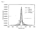
- FIG. 3 shows a relationship between an incident angle and an intensity profile. From the figure, it can be understood that a peak value becomes 2/3 with a deviation of 0.5 ⁇ rad from an ideal incident angle and that a collected beam profile is greatly collapsed in shape with a change in angle at a 1- ⁇ rad level. Meanwhile, FIG. 4 shows changes in Fresnel interference fringe and incident angle.
- an X-ray mirror (the longitudinal light collection mirror 5) is 400 mm long, a spacing between the incident-side planar reflective surface 9 and the outgoing-side reflective surface 10, both of which are 10-mm squares, is 380 mm, angles of both of the reflective surfaces (an angle of Fresnel mirror) are 3 ⁇ rad, and an incident angle of X-rays is 1 mrad.
- an X-ray mirror (the longitudinal light collection mirror 5) is 400 mm long, a spacing between the incident-side planar reflective surface 9 and the outgoing-side reflective surface 10, both of which are 10-mm squares, is 380 mm, angles of both of the reflective surfaces (an angle of Fresnel mirror) are 3 ⁇ rad, and an incident angle of X-rays is 1 mrad.
- FIG. 5 is a schematic view of an X-ray mirror according to the present invention, illustrating the longitudinal light collection mirror 5 as an example.
- This X-ray mirror is produced by forming the light collection surface zone 7 in a desired shape such as an ellipsoid in a middle portion of a Si single-crystal block with nano-level form accuracy.
- the pair of planar reflective surfaces 9 and 10 with a minute angle difference therebetween is formed in the vicinities of the incident-side end and outgoing-side end of the light collection surface zone 7, and both of the planar reflective surfaces 9 and 10 constitute a Fresnel mirror.
- a Fresnel interference fringe appears in parallel to a line of intersection of the planar reflective surfaces 9 and 10.
- the light collection surface zone 7 is of an ellipsoidal shape in this embodiment, the light collection surface zone 7 may be a cylindrical, paraboloidal, planar or any other optical functional surface.
- the Fresnel mirror integrally formed in the X-ray mirror it is possible to monitor an angle of the X-ray mirror and control a posture of the same.
- an X-ray mirror is shown as a typical example of an X-ray optical element, and further a K-B mirror is shown as a typical example of an X-ray mirror. It is obvious that a technical idea of the present invention of monitoring an interference fringe resulting from a Fresnel mirror integrally formed in an X-ray mirror to thereby control a posture of the X-ray mirror with high precision is not limited to X-ray mirrors but applicable to a wide variety of X-ray optical elements.
- the light collection surface zone 7 may be a strip-shaped reflective surface zone, may be a simple reflective surface zone which reflects X-rays only for changing a light path, or may be of a convex shape for diffusing or expanding X-rays.
- the light collection surface zone 7 or a reflective surface of a reflective surface zone may be a full-reflective surface or multilayer film.
- the light collection surface zone 7 and the reflective surface zone are strip-shaped because X-ray beams are favorably converged in this arrangement and thus the above zones need no high-precision processing.
- the X-ray light collector 2 with a K-B mirror arrangement reflects the incident X-ray beams 3 on the light collection surface zone 7 of the longitudinal light collection mirror 5 to thereby collect the beams in a longitudinal direction, reflects the beams on the light collection surface zone 8 of the lateral light collection mirror 6 to thereby collect the beams in a lateral direction, and then collects the beams at the focal point F common to the longitudinal light collection mirror 5 and the lateral light collection mirror 6.
- Fresnel fringes generated by the Fresnel mirrors incorporated into the longitudinal light collection mirror 5 and the lateral light collection mirror 6 are monitored, as shown in FIGs. 7 and 8 .
- the above is based on the assumption that the incident X-ray beam 3 with a certain spread enters the mirror, and a small or large portion of the beam reflects on the light collection surface zone 7 of the longitudinal light collection mirror 5, and the other portion goes off the light collection surface zone 7 and enters a side thereof. That is, as shown in FIG.
- the X-ray beam 3 also enters the pair of planar reflective surfaces 9 and 10 in the vicinities of the incident-side end and outgoing-side end of the light collection surface zone 7 in the longitudinal light collection mirror 5. Since the pair of planar reflective surfaces 9 and 10 constitutes a Fresnel mirror, the X-rays reflected on these reflective surfaces intersect at an intersection point V shown in the figure, and a Fresnel interference fringe is generated at this position.
- the X-ray beam 3 also enters directly the pair of planar reflective surfaces 11 and 12 in the vicinities of the incident-side end and outgoing-side end of the light collection surface zone 8 in the lateral light collection mirror 6. Since the pair of planar reflective surfaces 11 and 12 constitutes a Fresnel mirror, the X-rays reflected on these reflective surfaces intersect at an intersection point H shown in the figure, and a Fresnel interference fringe is generated at this position.
- an imaging camera 14 sensitive to target X-rays is disposed at the intersection point V
- an imaging camera 15 sensitive to X-rays is disposed at the intersection point H.
- the intersection point V spreads in a direction of an optical axis according to the sizes of the planar reflective surfaces 9 and 10. The same applies to the intersection point H.
- the imaging cameras 14 and 15 are CCD cameras which are disposed behind X-ray detection plates orthogonal to optical axes in the vicinities of the intersection points V and H, and acquire images, as electronic image data, which are affected by intensity distributions of X-rays from the detection plates.
- a change in Fresnel interference fringe is electrically detected, a detection signal is used as a feedback signal for posture control of the light collection mirrors, and the pulse-driven motors or actuators 16 and 17 for regulation of incident angles of the longitudinal light collection mirror 5 and lateral light collection mirror 6 are controlled to thereby regulate the incident angles with a precision of 1 ⁇ rad or less.
- X-ray detectors with a combination of a pinholes and a photo diode may be used as the imaging cameras 14 and 15 to acquire image data.
- Fresnel interference fringes resulting from the Fresnel mirrors are monitored by the imaging cameras 14 and 15, an interference fringe with the smallest light collection spot is set as reference image data, and a detection signal is generated through a comparison between the reference image data and current sequential image data. More specifically, a change in the sequential image data is detected with respect to the reference image data, and a pulse signal for driving the motors or actuators 16, 17 is generated until the sequential image data conforms to the reference image data in an allowable range, to thereby keep best postures of the longitudinal light collection mirror 5 and lateral light collection mirror 6.
Landscapes
- Physics & Mathematics (AREA)
- Spectroscopy & Molecular Physics (AREA)
- Engineering & Computer Science (AREA)
- General Engineering & Computer Science (AREA)
- High Energy & Nuclear Physics (AREA)
- General Physics & Mathematics (AREA)
- Optics & Photonics (AREA)
- Analysing Materials By The Use Of Radiation (AREA)
- Exposure Of Semiconductors, Excluding Electron Or Ion Beam Exposure (AREA)
Claims (8)
- Hochpräzises Lagesteuerungsverfahren eines Röntgenspiegels (5) zum Sammeln von Röntgenstrahlung (3) von harter Röntgenstrahlung bis zu weicher Röntgenstrahlung, oder zur Veränderung ihres Lichtwegs durch Reflexion der Röntgenstrahlung (3) an einer streifenförmigen reflektierenden Oberflächenzone (7), wobei ein Paar ebene reflektierende Oberflächen (9, 10) einen Fresnelschen Doppel-Spiegel bildet, wobei eine Oberfläche (9) des Paars von ebenen reflektierenden Oberflächen in der Nähe eines einfallseitigen Endes der reflektierenden Oberflächenzone ausgebildet ist und die andere Oberfläche (10) des Paars von ebenen reflektierenden Oberflächen in der Nähe eines austrittseitigen Endes der reflektierenden Oberflächenzone in dem Röntgenspiegel ausgebildet ist; wobei ein aus dem Fresnelschen Doppel-Spiegel resultierender Interferenzstreifen (13) in einer Position beobachtet wird, die nicht durch an der spiegelnden Oberflächenzone reflektierte Röntgenstrahlen beeinflusst wird; wobei eine Veränderung des Interferenzstreifens (13) elektrisch nachgewiesen wird; und wobei ein Nachweissignal als Rückführungssignal für die Lagesteuerung des Röntgenspiegels verwendet wird.
- Hochpräzises Lagesteuerungsverfahren eines Röntgenspiegels zum Sammeln von Röntgenstrahlung (3) von harter Röntgenstrahlung bis zu weicher Röntgenstrahlung bei hoher räumlicher Auflösung mit einem Fokusfleck von 100 nm oder weniger, wobei:ein longitudinaler Röntgensammelspiegel (5) so konfiguriert ist, dass er durch das hochpräzise Lagesteuerungsverfahren nach Anspruch 1 gesteuert wird, wobei eine streifenförmige reflektierende Oberfläche eine auf einer elliptischen reflektierenden Oberfläche ausgebildete Lichtsammlungs-Oberflächenzone (7) mit Brennpunkten an einer Lichtquelle und einer Lichtsammelfläche ist, und wobeiein seitlicher Lichtsammelspiegel (6) so konfiguriert ist, dass er durch das hochpräzise Lagesteuerungsverfahren nach Anspruch 1 gesteuert wird, wobei eine streifenförmige reflektierende Oberfläche eine auf einer elliptischen reflektierenden Oberfläche ausgebildete Lichtsammlungs-Oberflächenzone (8) mit Brennpunkten an einer Lichtquelle und einer Lichtsammelfläche ist, wobei der longitudinale Röntgensammelspiegel (5) und der seitliche Röntgensammelspiegel (6) in einer Kirkpatrick-Baez-Spiegelanordnung (2) senkrecht zueinander angeordnet sind; und wobeider longitudinale Lichtsammelspiegel (5) und der seitliche Lichtsammelspiegel (6) jeweils durch das hochpräzise Lagesteuerungsverfahren nach Anspruch 1 gesteuert werden.
- Hochpräzises Lagesteuerungsverfahren eines Röntgenspiegels nach Anspruch 2, wobei als Reaktion auf Nachweissignale von den am longitudinalen Röntgensammelspiegel (5) und am seitlichen Röntgensammelspiegel (6) vorgesehenen Fresnelschen Spiegeln impulsgesteuerte Motoren oder Stellantriebe (16, 17) zur Regulierung des Einfallswinkels gesteuert werden.
- Hochpräzises Lagesteuerungsverfahren eines Röntgenspiegels nach Anspruch 2 oder 3, wobei aus den Fresnelschen Spiegeln resultierende Interferenzstreifen (13) durch eine röntgenstrahlungsempfindliche bildgebende Kamera (14, 15) überwacht werden, ein Interferenzstreifen (13) an einem kleinsten Fokusfleck als Referenzbilddatenelement festgesetzt wird, und ein Nachweissignal aus einem Vergleich zwischen dem Referenzbilddatenelement und aktuellen sequentiellen Bilddaten generiert wird.
- Hochpräzises Lagesteuerungsverfahren eines Röntgenspiegels nach Anspruch 3, wobei aus den Fresnelschen Spiegeln resultierende Interferenzstreifen (13) durch eine röntgenstrahlungsempfindliche bildgebende Kamera (14, 15) überwacht werden, ein Interferenzstreifen an einem kleinsten Fokusfleck als Referenzbilddatenelement festgesetzt wird, eine Veränderung der sequentiellen Bilddaten bezüglich des Referenzbilddatenelements erfasst wird, und ein Impulssignal zum Ansteuern der Motoren oder Stellantriebe (16, 17) erzeugt wird, bis die sequentiellen Bilddaten dem Referenzbilddatenelement in einem zulässigen Bereich entsprechen.
- Hochpräzises Lagesteuerungsverfahren eines Röntgenspiegels nach Anspruch 4 oder 5, wobei die bildgebende Kamera (14, 15) eine CCD-Kamera ist.
- Hochpräzises Lagesteuerungsverfahren eines Röntgenspiegels nach Anspruch 4 oder 5, wobei die bildgebende Kamera ein Röntgenstrahlungsdetektor mit einer Kombination aus einem feinen Loch und einer Photodiode ist.
- Röntgenspiegel, der eine hochpräzise Lagesteuerung für das Sammeln von Röntgenstrahlung (3) oder für die Veränderung ihres Lichtwegs durch Reflexion der Röntgenstrahlung (3) ermöglicht,
wobei der Röntgenspiegel aufweist:eine streifenförmige reflektierende Oberflächenzone (7) und ein Paar ebene reflektierende Oberflächen (9, 10), wobei die streifenförmige reflektierende Oberflächenzone (7) so angeordnet ist, dass sie von einer Röntgenstrahlungsquelle (O) emittierte Röntgenstrahlen (3) reflektiert,wobei die streifenförmige reflektierende Oberflächenzone (7) in Längsrichtung ausgebildet ist und sich zwischen einem einfallseitigen Ende der streifenförmigen reflektierenden Oberflächenzone (7) und einem austrittseitigen Ende der streifenförmigen reflektierenden Oberflächenzone (7) erstreckt,und wobei eine ebene reflektierende Oberfläche (9) des Paars von ebenen reflektierenden Oberflächen in der Nähe des einfallseitigen Endes der reflektierenden Oberflächenzone ausgebildet ist und die andere (10) von dem Paar von ebenen reflektierenden Oberflächen in der Nähe des austrittseitigen Endes der reflektierenden Oberflächenzone ausgebildet ist,wobei der Röntgenspiegel dadurch gekennzeichnet ist, dass das Paar von ebenen reflektierenden Oberflächen (9, 10) so angeordnet ist, dass es einen Fresnelschen Doppel-Spiegel für Röntgenstrahlen (3) bildet, die von der Röntgenstrahlungsquelle (O) emittiert werden.
Applications Claiming Priority (2)
| Application Number | Priority Date | Filing Date | Title |
|---|---|---|---|
| JP2006221714A JP4557939B2 (ja) | 2006-07-18 | 2006-07-18 | X線ミラーの高精度姿勢制御法およびx線ミラー |
| PCT/JP2007/064098 WO2008010491A1 (en) | 2006-07-18 | 2007-07-17 | High precision posture control method of x-ray mirror |
Publications (3)
| Publication Number | Publication Date |
|---|---|
| EP2045820A1 EP2045820A1 (de) | 2009-04-08 |
| EP2045820A4 EP2045820A4 (de) | 2010-08-18 |
| EP2045820B1 true EP2045820B1 (de) | 2012-10-10 |
Family
ID=38956822
Family Applications (1)
| Application Number | Title | Priority Date | Filing Date |
|---|---|---|---|
| EP07790860A Not-in-force EP2045820B1 (de) | 2006-07-18 | 2007-07-17 | Hochpräzises haltungssteuerverfahren eines röntgenspiegels |
Country Status (4)
| Country | Link |
|---|---|
| US (1) | US8000443B2 (de) |
| EP (1) | EP2045820B1 (de) |
| JP (1) | JP4557939B2 (de) |
| WO (1) | WO2008010491A1 (de) |
Families Citing this family (7)
| Publication number | Priority date | Publication date | Assignee | Title |
|---|---|---|---|---|
| US8450475B2 (en) | 2008-08-04 | 2013-05-28 | Allergan, Inc. | Hyaluronic acid-based gels including lidocaine |
| JP5756982B2 (ja) * | 2009-12-28 | 2015-07-29 | 株式会社ジェイテック | X線集光方法、反射面形状制御ミラー装置及び反射面形状制御ミラーの製造方法 |
| CN102103255B (zh) * | 2011-01-28 | 2012-08-29 | 中国科学院高能物理研究所 | 同步辐射垂直聚焦镜的重力协弯方法 |
| FR2978824B1 (fr) * | 2011-08-05 | 2014-03-21 | Thales Sa | Systeme a detection de posture interferometrique |
| JP7343111B2 (ja) * | 2019-08-09 | 2023-09-12 | 株式会社ジェイテックコーポレーション | 対向型x線複合ミラー |
| CN111766713B (zh) * | 2020-06-30 | 2021-07-20 | 同济大学 | 一种非球面超高分辨kb显微镜的装调装置和装调方法 |
| JP7804278B2 (ja) * | 2022-02-04 | 2026-01-22 | 株式会社ジェイテックコーポレーション | 対向型x線複合ミラー及びそのアライメント装置 |
Family Cites Families (9)
| Publication number | Priority date | Publication date | Assignee | Title |
|---|---|---|---|---|
| US3772464A (en) * | 1972-04-17 | 1973-11-13 | Spectrotherm Corp | Rotating polygon mirror assembly with an interior motor |
| US5272570A (en) * | 1990-05-02 | 1993-12-21 | Asahi Kogaku Kogyo Kabushiki Kaisha | Illuminating reflection apparatus |
| JPH0445417A (ja) * | 1990-06-13 | 1992-02-14 | Fujitsu Ltd | 光線反射鏡 |
| JPH07253528A (ja) * | 1994-03-16 | 1995-10-03 | Olympus Optical Co Ltd | 光軸調整装置 |
| JPH08271697A (ja) | 1995-03-28 | 1996-10-18 | Canon Inc | X線顕微鏡用光学装置 |
| JP2000077305A (ja) * | 1998-08-31 | 2000-03-14 | Nikon Corp | 反射マスクおよびx線投影露光装置 |
| DE10162093A1 (de) * | 2001-12-18 | 2003-07-10 | Bruker Axs Gmbh | Röntgen-optisches System mit Blende im Fokus einer Röntgen-Spiegels |
| US7126671B2 (en) * | 2003-04-04 | 2006-10-24 | Asml Netherlands B.V. | Lithographic apparatus and device manufacturing method |
| JP4278108B2 (ja) * | 2006-07-07 | 2009-06-10 | 株式会社リガク | 超小角x線散乱測定装置 |
-
2006
- 2006-07-18 JP JP2006221714A patent/JP4557939B2/ja not_active Expired - Fee Related
-
2007
- 2007-07-17 US US12/374,137 patent/US8000443B2/en not_active Expired - Fee Related
- 2007-07-17 EP EP07790860A patent/EP2045820B1/de not_active Not-in-force
- 2007-07-17 WO PCT/JP2007/064098 patent/WO2008010491A1/ja not_active Ceased
Non-Patent Citations (1)
| Title |
|---|
| GRANT R. FOWLES: "Introduction to Modern Optics", 1 January 1989, DOVER PUBLICATIONS, pages: 62 * |
Also Published As
| Publication number | Publication date |
|---|---|
| JP2008026294A (ja) | 2008-02-07 |
| US8000443B2 (en) | 2011-08-16 |
| US20100002838A1 (en) | 2010-01-07 |
| EP2045820A1 (de) | 2009-04-08 |
| EP2045820A4 (de) | 2010-08-18 |
| WO2008010491A1 (en) | 2008-01-24 |
| JP4557939B2 (ja) | 2010-10-06 |
Similar Documents
| Publication | Publication Date | Title |
|---|---|---|
| EP2045820B1 (de) | Hochpräzises haltungssteuerverfahren eines röntgenspiegels | |
| US10712667B2 (en) | Optical device and associated system | |
| US7122814B2 (en) | Arrangement for the stabilization of the radiation emission of a plasma | |
| US7599071B2 (en) | Determining positional error of an optical component using structured light patterns | |
| EP0411966B1 (de) | Verfahren und Vorrichtung zur Positionsbestimmung | |
| US8120996B2 (en) | Device and method for microstructuring a storage medium and storage medium comprising a microstructured region | |
| US11099400B2 (en) | Beam propagation camera and method for light beam analysis | |
| EP0020076A1 (de) | Vorrichtung zum optischen Abtasten | |
| CA2620941A1 (en) | Imaging system and method | |
| JP6048867B2 (ja) | X線光学システム | |
| JP6576435B2 (ja) | ビーム誘導光学系から誘導される光線を分析するためのシステム及び方法 | |
| EP2439589B1 (de) | Röntgenstrahlbild-Fotografierverfahren und Röntgenstrahlbild-Fotografiervorrichtung | |
| JP3902796B2 (ja) | 回折測距システム用可変ピッチ格子 | |
| Ding et al. | A compact and high-precision method for active beam stabilization system | |
| US11409199B2 (en) | Pattern drawing device | |
| JP7656311B2 (ja) | 光学装置 | |
| Hofmann et al. | Model-based analysis of highly dynamic laser beam shaping using deformable mirrors | |
| TWI431321B (zh) | 形塑雷射光束的輪廓的光學系統及方法 | |
| WO2023161390A1 (en) | Telescope with optical alignment system | |
| Tian et al. | An active piezoelectric plane X-ray focusing mirror with a linearly changing thickness | |
| US20110001948A1 (en) | Illumination system for a microlithography projection exposure apparatus | |
| Beckers et al. | Planning The National New Technology Telescope (NNTT) IV. Coalignment/Cophasing System | |
| Zhou et al. | At-wavelength metrology of an X-ray mirror using a downstream wavefront modulator | |
| Leonov et al. | Measurement setup for quality control of a Fresnel zone plate with pinholes | |
| Wang et al. | A novel extreme ultraviolet four channels normal incidence imaging system for plasma diagnostics of Z-pinch facility |
Legal Events
| Date | Code | Title | Description |
|---|---|---|---|
| PUAI | Public reference made under article 153(3) epc to a published international application that has entered the european phase |
Free format text: ORIGINAL CODE: 0009012 |
|
| 17P | Request for examination filed |
Effective date: 20090126 |
|
| AK | Designated contracting states |
Kind code of ref document: A1 Designated state(s): AT BE BG CH CY CZ DE DK EE ES FI FR GB GR HU IE IS IT LI LT LU LV MC MT NL PL PT RO SE SI SK TR |
|
| AX | Request for extension of the european patent |
Extension state: AL BA HR MK RS |
|
| A4 | Supplementary search report drawn up and despatched |
Effective date: 20100720 |
|
| 17Q | First examination report despatched |
Effective date: 20110628 |
|
| GRAP | Despatch of communication of intention to grant a patent |
Free format text: ORIGINAL CODE: EPIDOSNIGR1 |
|
| DAX | Request for extension of the european patent (deleted) | ||
| GRAS | Grant fee paid |
Free format text: ORIGINAL CODE: EPIDOSNIGR3 |
|
| GRAA | (expected) grant |
Free format text: ORIGINAL CODE: 0009210 |
|
| RIN1 | Information on inventor provided before grant (corrected) |
Inventor name: OKADA, HIROMI Inventor name: YAMAUCHI, KAZUTO Inventor name: MIMURA, HIDEKAZU |
|
| AK | Designated contracting states |
Kind code of ref document: B1 Designated state(s): AT BE BG CH CY CZ DE DK EE ES FI FR GB GR HU IE IS IT LI LT LU LV MC MT NL PL PT RO SE SI SK TR |
|
| REG | Reference to a national code |
Ref country code: GB Ref legal event code: FG4D |
|
| REG | Reference to a national code |
Ref country code: AT Ref legal event code: REF Ref document number: 579282 Country of ref document: AT Kind code of ref document: T Effective date: 20121015 Ref country code: CH Ref legal event code: EP |
|
| REG | Reference to a national code |
Ref country code: IE Ref legal event code: FG4D |
|
| REG | Reference to a national code |
Ref country code: DE Ref legal event code: R096 Ref document number: 602007026018 Country of ref document: DE Effective date: 20121206 |
|
| PG25 | Lapsed in a contracting state [announced via postgrant information from national office to epo] |
Ref country code: SI Free format text: LAPSE BECAUSE OF FAILURE TO SUBMIT A TRANSLATION OF THE DESCRIPTION OR TO PAY THE FEE WITHIN THE PRESCRIBED TIME-LIMIT Effective date: 20121010 |
|
| REG | Reference to a national code |
Ref country code: NL Ref legal event code: VDEP Effective date: 20121010 |
|
| REG | Reference to a national code |
Ref country code: AT Ref legal event code: MK05 Ref document number: 579282 Country of ref document: AT Kind code of ref document: T Effective date: 20121010 |
|
| REG | Reference to a national code |
Ref country code: LT Ref legal event code: MG4D |
|
| PG25 | Lapsed in a contracting state [announced via postgrant information from national office to epo] |
Ref country code: IS Free format text: LAPSE BECAUSE OF FAILURE TO SUBMIT A TRANSLATION OF THE DESCRIPTION OR TO PAY THE FEE WITHIN THE PRESCRIBED TIME-LIMIT Effective date: 20130210 Ref country code: ES Free format text: LAPSE BECAUSE OF FAILURE TO SUBMIT A TRANSLATION OF THE DESCRIPTION OR TO PAY THE FEE WITHIN THE PRESCRIBED TIME-LIMIT Effective date: 20130121 Ref country code: SE Free format text: LAPSE BECAUSE OF FAILURE TO SUBMIT A TRANSLATION OF THE DESCRIPTION OR TO PAY THE FEE WITHIN THE PRESCRIBED TIME-LIMIT Effective date: 20121010 Ref country code: FI Free format text: LAPSE BECAUSE OF FAILURE TO SUBMIT A TRANSLATION OF THE DESCRIPTION OR TO PAY THE FEE WITHIN THE PRESCRIBED TIME-LIMIT Effective date: 20121010 Ref country code: NL Free format text: LAPSE BECAUSE OF FAILURE TO SUBMIT A TRANSLATION OF THE DESCRIPTION OR TO PAY THE FEE WITHIN THE PRESCRIBED TIME-LIMIT Effective date: 20121010 Ref country code: LT Free format text: LAPSE BECAUSE OF FAILURE TO SUBMIT A TRANSLATION OF THE DESCRIPTION OR TO PAY THE FEE WITHIN THE PRESCRIBED TIME-LIMIT Effective date: 20121010 |
|
| PG25 | Lapsed in a contracting state [announced via postgrant information from national office to epo] |
Ref country code: PL Free format text: LAPSE BECAUSE OF FAILURE TO SUBMIT A TRANSLATION OF THE DESCRIPTION OR TO PAY THE FEE WITHIN THE PRESCRIBED TIME-LIMIT Effective date: 20121010 Ref country code: GR Free format text: LAPSE BECAUSE OF FAILURE TO SUBMIT A TRANSLATION OF THE DESCRIPTION OR TO PAY THE FEE WITHIN THE PRESCRIBED TIME-LIMIT Effective date: 20130111 Ref country code: BE Free format text: LAPSE BECAUSE OF FAILURE TO SUBMIT A TRANSLATION OF THE DESCRIPTION OR TO PAY THE FEE WITHIN THE PRESCRIBED TIME-LIMIT Effective date: 20121010 Ref country code: PT Free format text: LAPSE BECAUSE OF FAILURE TO SUBMIT A TRANSLATION OF THE DESCRIPTION OR TO PAY THE FEE WITHIN THE PRESCRIBED TIME-LIMIT Effective date: 20130211 Ref country code: CY Free format text: LAPSE BECAUSE OF FAILURE TO SUBMIT A TRANSLATION OF THE DESCRIPTION OR TO PAY THE FEE WITHIN THE PRESCRIBED TIME-LIMIT Effective date: 20121010 Ref country code: LV Free format text: LAPSE BECAUSE OF FAILURE TO SUBMIT A TRANSLATION OF THE DESCRIPTION OR TO PAY THE FEE WITHIN THE PRESCRIBED TIME-LIMIT Effective date: 20121010 |
|
| PG25 | Lapsed in a contracting state [announced via postgrant information from national office to epo] |
Ref country code: AT Free format text: LAPSE BECAUSE OF FAILURE TO SUBMIT A TRANSLATION OF THE DESCRIPTION OR TO PAY THE FEE WITHIN THE PRESCRIBED TIME-LIMIT Effective date: 20121010 |
|
| PG25 | Lapsed in a contracting state [announced via postgrant information from national office to epo] |
Ref country code: EE Free format text: LAPSE BECAUSE OF FAILURE TO SUBMIT A TRANSLATION OF THE DESCRIPTION OR TO PAY THE FEE WITHIN THE PRESCRIBED TIME-LIMIT Effective date: 20121010 Ref country code: BG Free format text: LAPSE BECAUSE OF FAILURE TO SUBMIT A TRANSLATION OF THE DESCRIPTION OR TO PAY THE FEE WITHIN THE PRESCRIBED TIME-LIMIT Effective date: 20130110 Ref country code: DK Free format text: LAPSE BECAUSE OF FAILURE TO SUBMIT A TRANSLATION OF THE DESCRIPTION OR TO PAY THE FEE WITHIN THE PRESCRIBED TIME-LIMIT Effective date: 20121010 Ref country code: SK Free format text: LAPSE BECAUSE OF FAILURE TO SUBMIT A TRANSLATION OF THE DESCRIPTION OR TO PAY THE FEE WITHIN THE PRESCRIBED TIME-LIMIT Effective date: 20121010 Ref country code: CZ Free format text: LAPSE BECAUSE OF FAILURE TO SUBMIT A TRANSLATION OF THE DESCRIPTION OR TO PAY THE FEE WITHIN THE PRESCRIBED TIME-LIMIT Effective date: 20121010 |
|
| PLBE | No opposition filed within time limit |
Free format text: ORIGINAL CODE: 0009261 |
|
| STAA | Information on the status of an ep patent application or granted ep patent |
Free format text: STATUS: NO OPPOSITION FILED WITHIN TIME LIMIT |
|
| PG25 | Lapsed in a contracting state [announced via postgrant information from national office to epo] |
Ref country code: IT Free format text: LAPSE BECAUSE OF FAILURE TO SUBMIT A TRANSLATION OF THE DESCRIPTION OR TO PAY THE FEE WITHIN THE PRESCRIBED TIME-LIMIT Effective date: 20121010 Ref country code: RO Free format text: LAPSE BECAUSE OF FAILURE TO SUBMIT A TRANSLATION OF THE DESCRIPTION OR TO PAY THE FEE WITHIN THE PRESCRIBED TIME-LIMIT Effective date: 20121010 |
|
| 26N | No opposition filed |
Effective date: 20130711 |
|
| REG | Reference to a national code |
Ref country code: DE Ref legal event code: R097 Ref document number: 602007026018 Country of ref document: DE Effective date: 20130711 |
|
| PG25 | Lapsed in a contracting state [announced via postgrant information from national office to epo] |
Ref country code: MC Free format text: LAPSE BECAUSE OF FAILURE TO SUBMIT A TRANSLATION OF THE DESCRIPTION OR TO PAY THE FEE WITHIN THE PRESCRIBED TIME-LIMIT Effective date: 20121010 |
|
| REG | Reference to a national code |
Ref country code: CH Ref legal event code: PL |
|
| REG | Reference to a national code |
Ref country code: IE Ref legal event code: MM4A |
|
| PG25 | Lapsed in a contracting state [announced via postgrant information from national office to epo] |
Ref country code: LI Free format text: LAPSE BECAUSE OF NON-PAYMENT OF DUE FEES Effective date: 20130731 Ref country code: CH Free format text: LAPSE BECAUSE OF NON-PAYMENT OF DUE FEES Effective date: 20130731 |
|
| PG25 | Lapsed in a contracting state [announced via postgrant information from national office to epo] |
Ref country code: IE Free format text: LAPSE BECAUSE OF NON-PAYMENT OF DUE FEES Effective date: 20130717 |
|
| PG25 | Lapsed in a contracting state [announced via postgrant information from national office to epo] |
Ref country code: TR Free format text: LAPSE BECAUSE OF FAILURE TO SUBMIT A TRANSLATION OF THE DESCRIPTION OR TO PAY THE FEE WITHIN THE PRESCRIBED TIME-LIMIT Effective date: 20121010 Ref country code: MT Free format text: LAPSE BECAUSE OF FAILURE TO SUBMIT A TRANSLATION OF THE DESCRIPTION OR TO PAY THE FEE WITHIN THE PRESCRIBED TIME-LIMIT Effective date: 20121010 |
|
| REG | Reference to a national code |
Ref country code: FR Ref legal event code: PLFP Year of fee payment: 9 |
|
| PG25 | Lapsed in a contracting state [announced via postgrant information from national office to epo] |
Ref country code: HU Free format text: LAPSE BECAUSE OF FAILURE TO SUBMIT A TRANSLATION OF THE DESCRIPTION OR TO PAY THE FEE WITHIN THE PRESCRIBED TIME-LIMIT; INVALID AB INITIO Effective date: 20070717 Ref country code: LU Free format text: LAPSE BECAUSE OF NON-PAYMENT OF DUE FEES Effective date: 20130717 |
|
| REG | Reference to a national code |
Ref country code: FR Ref legal event code: PLFP Year of fee payment: 10 |
|
| REG | Reference to a national code |
Ref country code: FR Ref legal event code: PLFP Year of fee payment: 11 |
|
| REG | Reference to a national code |
Ref country code: FR Ref legal event code: PLFP Year of fee payment: 12 |
|
| PGFP | Annual fee paid to national office [announced via postgrant information from national office to epo] |
Ref country code: FR Payment date: 20200624 Year of fee payment: 14 |
|
| PGFP | Annual fee paid to national office [announced via postgrant information from national office to epo] |
Ref country code: DE Payment date: 20200729 Year of fee payment: 14 Ref country code: GB Payment date: 20200708 Year of fee payment: 14 |
|
| REG | Reference to a national code |
Ref country code: DE Ref legal event code: R119 Ref document number: 602007026018 Country of ref document: DE |
|
| GBPC | Gb: european patent ceased through non-payment of renewal fee |
Effective date: 20210717 |
|
| PG25 | Lapsed in a contracting state [announced via postgrant information from national office to epo] |
Ref country code: GB Free format text: LAPSE BECAUSE OF NON-PAYMENT OF DUE FEES Effective date: 20210717 Ref country code: DE Free format text: LAPSE BECAUSE OF NON-PAYMENT OF DUE FEES Effective date: 20220201 |
|
| PG25 | Lapsed in a contracting state [announced via postgrant information from national office to epo] |
Ref country code: FR Free format text: LAPSE BECAUSE OF NON-PAYMENT OF DUE FEES Effective date: 20210731 |