EP2043570B1 - Elastische vorrichtung - Google Patents
Elastische vorrichtung Download PDFInfo
- Publication number
- EP2043570B1 EP2043570B1 EP07812764.4A EP07812764A EP2043570B1 EP 2043570 B1 EP2043570 B1 EP 2043570B1 EP 07812764 A EP07812764 A EP 07812764A EP 2043570 B1 EP2043570 B1 EP 2043570B1
- Authority
- EP
- European Patent Office
- Prior art keywords
- working
- working portion
- anchoring
- equivalent diameter
- wire
- Prior art date
- Legal status (The legal status is an assumption and is not a legal conclusion. Google has not performed a legal analysis and makes no representation as to the accuracy of the status listed.)
- Not-in-force
Links
Images


Classifications
-
- A—HUMAN NECESSITIES
- A61—MEDICAL OR VETERINARY SCIENCE; HYGIENE
- A61F—FILTERS IMPLANTABLE INTO BLOOD VESSELS; PROSTHESES; DEVICES PROVIDING PATENCY TO, OR PREVENTING COLLAPSING OF, TUBULAR STRUCTURES OF THE BODY, e.g. STENTS; ORTHOPAEDIC, NURSING OR CONTRACEPTIVE DEVICES; FOMENTATION; TREATMENT OR PROTECTION OF EYES OR EARS; BANDAGES, DRESSINGS OR ABSORBENT PADS; FIRST-AID KITS
- A61F6/00—Contraceptive devices; Pessaries; Applicators therefor
- A61F6/06—Contraceptive devices; Pessaries; Applicators therefor for use by females
- A61F6/08—Pessaries, i.e. devices worn in the vagina to support the uterus, remedy a malposition or prevent conception, e.g. combined with devices protecting against contagion
-
- A—HUMAN NECESSITIES
- A61—MEDICAL OR VETERINARY SCIENCE; HYGIENE
- A61F—FILTERS IMPLANTABLE INTO BLOOD VESSELS; PROSTHESES; DEVICES PROVIDING PATENCY TO, OR PREVENTING COLLAPSING OF, TUBULAR STRUCTURES OF THE BODY, e.g. STENTS; ORTHOPAEDIC, NURSING OR CONTRACEPTIVE DEVICES; FOMENTATION; TREATMENT OR PROTECTION OF EYES OR EARS; BANDAGES, DRESSINGS OR ABSORBENT PADS; FIRST-AID KITS
- A61F2/00—Filters implantable into blood vessels; Prostheses, i.e. artificial substitutes or replacements for parts of the body; Appliances for connecting them with the body; Devices providing patency to, or preventing collapsing of, tubular structures of the body, e.g. stents
- A61F2/0004—Closure means for urethra or rectum, i.e. anti-incontinence devices or support slings against pelvic prolapse
- A61F2/0031—Closure means for urethra or rectum, i.e. anti-incontinence devices or support slings against pelvic prolapse for constricting the lumen; Support slings for the urethra
- A61F2/005—Closure means for urethra or rectum, i.e. anti-incontinence devices or support slings against pelvic prolapse for constricting the lumen; Support slings for the urethra with pressure applied to urethra by an element placed in the vagina
-
- A—HUMAN NECESSITIES
- A61—MEDICAL OR VETERINARY SCIENCE; HYGIENE
- A61F—FILTERS IMPLANTABLE INTO BLOOD VESSELS; PROSTHESES; DEVICES PROVIDING PATENCY TO, OR PREVENTING COLLAPSING OF, TUBULAR STRUCTURES OF THE BODY, e.g. STENTS; ORTHOPAEDIC, NURSING OR CONTRACEPTIVE DEVICES; FOMENTATION; TREATMENT OR PROTECTION OF EYES OR EARS; BANDAGES, DRESSINGS OR ABSORBENT PADS; FIRST-AID KITS
- A61F6/00—Contraceptive devices; Pessaries; Applicators therefor
- A61F6/06—Contraceptive devices; Pessaries; Applicators therefor for use by females
- A61F6/08—Pessaries, i.e. devices worn in the vagina to support the uterus, remedy a malposition or prevent conception, e.g. combined with devices protecting against contagion
- A61F6/12—Inserters or removers
-
- Y—GENERAL TAGGING OF NEW TECHNOLOGICAL DEVELOPMENTS; GENERAL TAGGING OF CROSS-SECTIONAL TECHNOLOGIES SPANNING OVER SEVERAL SECTIONS OF THE IPC; TECHNICAL SUBJECTS COVERED BY FORMER USPC CROSS-REFERENCE ART COLLECTIONS [XRACs] AND DIGESTS
- Y10—TECHNICAL SUBJECTS COVERED BY FORMER USPC
- Y10T—TECHNICAL SUBJECTS COVERED BY FORMER US CLASSIFICATION
- Y10T29/00—Metal working
- Y10T29/49—Method of mechanical manufacture
- Y10T29/49826—Assembling or joining
Definitions
- the present invention relates to a resilient device. More specifically, this invention relates to a device that has a working portion having a variable equivalent diameter, and an anchoring mechanism.
- the device is useful, e.g., for reducing or preventing urinary incontinence.
- Stress urinary incontinence is a problem for many women. It is characterized by leakage of urine during a stressing event, such as a cough or a sneeze. Many devices have been designed to reduce or prevent stress urinary incontinence.
- US Pat. No. 5,603,685 teaches inflatable devices and a means to provide a device that is small for insertion into the vagina and enlarges to a required shape and pressure to reduce or prevent urinary incontinence.
- US Pat. No. 6,090,098 teaches tampon-like devices, each made with a combination of absorbing and/or non-absorbing fibrous materials.
- US Pat. No. 6,645,137 teaches a coil that expands in the vagina.
- US Pat. No. 5,036,867 teaches a compressible resilient pessary.
- US Pat. No. 6,460,542 teaches a highly shaped rigid pessary. Many patents are drawn to stents that are sized and designed to keep
- WO 2006/097935 (prior art under Art. 54(3) EPC) and WO 2005/087154 disclose an apparatus for treating urinary incontinence, comprising: a node; a support section adapted for providing urethral support; an anchoring section for resisting movement of the apparatus; an insert, a portion of which is adapted to be positioned where the support section attaches to the node; and, wherein the insert urges the support section radially outwards from a central axis of the apparatus.
- WO2004103213 discusses a device for controlling urinary incontinence adapted for being inserted into the vagina comprising both a pressure providing member and an anchoring member to prevent slippage of the device in the vagina.
- US5036867 and EP0264258 discuss an intra-vaginal device to aid in controlling urinary incontinence, the device includes a central portion of an arcuate configuration to be positioned within the vagina in an upwardly convex orientation, a pair of rearward projections which engage the posterior vaginal wall, a pair of forward projections which engage the anterior vaginal wall adjacent the bladder neck to lift the bladder adjacent thereto, a bladder neck cradle to cradle the bladder neck, with the device being formed of resilient material so as to flex into engagement with the vaginal wall to be retained in position.
- an intravaginal device includes a working portion and an anchoring portion.
- the anchoring portion has at least one member extending beyond at least one end of the working portion to maintain the working portion in place during use.
- an intravaginal urinary incontinence device in another embodiment, includes a stent having a working portion having opposed faces to provide support to an associated urinary system; and an anchoring portion to maintain the stent in place during use.
- the anchoring portion has at least one member extending beyond at least one end of the working portion.
- wire form and variants thereof relate to a structure formed of at least one wire or wire-like material that is manipulated and optionally secured (e.g., by welding) in a desired three-dimensional structure.
- shape memory material and variants thereof relate to materials that can be shaped into an initial shape, which initial shape can be subsequently formed into a stable second shape.
- the material is capable of substantially reverting to its initial shape upon exposure to an appropriate event, including without limitation mechanical deformation and a change in temperature.
- the term "stent” and variants thereof relate to a device used to support a bodily orifice, cavity, vessel, and the like.
- the stent is resilient, flexible, and collapsible with memory.
- the stent has a wire form.
- a “stent” is a device used to support a bodily orifice, cavity, vessel, and the like.
- the stent is resilient, flexible, and collapsible with memory.
- the stent has a wire form.
- the device 10 has a working portion 1 which is generally cylindrical in shape and contains working surfaces 9a and 9b.
- Working portion 1 has an initial equivalent diameter d ranging from about 20 mm to about 170 mm and a length L1 ranging from about 15 mm to about 60 mm. Where the working portion is non-cylindrical, the equivalent diameter is the maximum distance in millimeters between the opposed working surfaces.
- working portion 1 has an insertion (in an applicator or other device for insertion) equivalent diameter d 2 ranging from about 5 mm to about 20 mm.
- working portion 1 has a use equivalent diameter (in the vagina) d 3 ranging from about 5 mm to about 40 mm.
- Working portion 1 may be made of any elastic material that compresses and recovers with sufficient force to provide the desired effect.
- the working portion 1 is made of Nitinol wire 20 and comprises alternating sinusoidal struts 2, 3 which intersect and form a strut angle ⁇ . Alternating struts 2, 3 have a length L2 and L3 equal to the working portion length.
- the working pressure exerted by working portion 1 is determined by the thickness of the wire, the number of wires, the length of the struts and the strut angle, and the number of times the working portion is heat-treated.
- the number of wires may range from about 1 to about 20.
- the wires may be separate, twisted, or braided.
- the working portion exerts a pressure of from about 5 to about 250 cm H 2 O in the working state.
- Device 10 has anchoring means, e.g., anchoring portion 4.
- Anchoring portion 4 is designed to keep the device in place when in use.
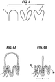
- Anchoring portion 4 is shaped suitable to keep the device in place while in use. Suitable shapes include, but are not limited to, a basket handle 5, rabbit ears 6, and a dog bone 7, as shown in FIG. 5 .
- the anchoring portion is made of the same material as the working portion, i.e. a shape memory alloy.
- the working portion and anchoring portion may be made as a uni-body construction, or may be made separately and joined by attachment means, such as silicone tubing 22.
- the devices may be treated to provide improved biocompatibility.
- the device may be placed inside tubing, for example silicone tubing, or may be dip coated in suitable polymeric materials.
- Devices according to the present invention may be useful for treating or preventing urinary incontinence.
- the device is sized to fit comfortably in the vagina. All of the devices described below may have working portions with initial equivalent diameters of from about 20 to about 170 mm.
- the working portion has a generally cylindrical working portion that may have an initial equivalent diameter ranging from about 20 to about 170 mm, preferably about 20 to about 45 mm, or more preferably about 30 mm; an insertion equivalent diameter ranging from about 5 to about 25 mm, preferably about 10 to about 20 mm, or more preferably about 18 mm; a use equivalent diameter ranging from about 20 to about 40 mm, preferably about 25 to about 30 mm, or more preferably about 25 mm; and a length ranging from about 20 to about 60 mm, preferably about 20 to about 30 mm, or more preferably about 25 mm.
- the anchoring portion extends beyond the working portion and may have an initial equivalent diameter ranging from about 20 to about 60 mm, preferably about 40 to about 60 mm, or more preferably about 50 mm; an insertion equivalent diameter ranging from about 10 to about 25 mm, preferably about 10 to about 20 mm, or more preferably about 18 mm; a use equivalent diameter ranging from about 20 to about 60 mm, preferably about 40 to about 60 mm, or more preferably about 50 mm; and a length ranging from about 10 to about 50 mm, preferably about 20 to about 40 mm, or more preferably about 30 mm.
- the working portion of the device has a length and equivalent diameter in the insertion state, the working state, and the removal state.
- the insertion state length may range from about 20 to about 30 mm, for example about 25 mm.
- the insertion state equivalent diameter may range from about 5 to about 20 mm, for example about 18 mm.
- the working state length at rest and during a cough may range from about 20 to about 30 mm, for example about 25 mm.
- the working state equivalent diameter at rest may range from about 20 to about 30 mm, for example about 25 mm.
- the working state equivalent diameter during a cough may range from about 15 to about 25 mm, for example about 20 mm.
- the removal state length may range from about 20 to about 30 mm, for example about 25 mm.
- the removal state equivalent diameter may range from about 15 to about 20 mm, for example about 18 mm.
- the anchoring portion of the device has a length and width in the insertion state, the working state, and the removal state.
- the insertion state length may range from about 25 to about 40 mm, for example about 30 mm.
- the insertion state width may range from about 15 to about 20 mm, for example about 18 mm.
- the working state length at rest and during a cough may range from about 25 to about 40 mm, for example about 30 mm.
- the working state width at rest and during a cough may range from about 25 to about 35 mm, for example about 30 mm.
- the removal state length may range from about 30 to about 50 mm, for example about 40 mm.
- the removal state width may range from about 15 to about 20 mm, for example about 18 mm.
- the working portion of the device has a length and equivalent diameter in the insertion state, the working state, and the removal state.
- the insertion state length may range from about 25 to about 60 mm, for example about 45 mm.
- the insertion state equivalent diameter may range from about 5 to about 20 mm, for example about 18 mm.
- the working state length at rest and during a cough may range from about 25 to about 60 mm, for example about 45 mm.
- the working state equivalent diameter at rest may range from about 20 to about 30 mm, for example about 25 mm.
- the working state equivalent diameter during a cough may range from about 15 to about 25 mm, for example about 20 mm.
- the removal state length may range from about 25 to about 60 mm, for example about 45 mm.
- the removal state equivalent diameter may range from about 15 to about 20 mm, for example about 18 mm.
- the working portion of the device has a length and equivalent diameter in the insertion state, the working state, and the removal state.
- the insertion state length may range from about 20 to about 30 mm, for example about 25 mm.
- the insertion state equivalent diameter may range from about 10 to about 20 mm, for example about 15 mm.
- the working state length at rest and during a cough may range from about 20 to about 30 mm, for example about 25 mm.
- the working state equivalent diameter at rest and during a cough may range from about 10 to about 30 mm, for example about 18 mm.
- the removal state length may range from about 20 to about 30 mm, for example about 25 mm.
- the removal state equivalent diameter may range from about 10 to about 20 mm, for example about 15 mm.
- the height of the working portion in all states may range from about 20 to about 30 mm, for example about 25 mm.
- the anchoring portion of the device has a length and width in the insertion state, the working state, and the removal state.
- the insertion state length may range from about 20 to about 50 mm, for example about 30 mm.
- the insertion width may range from about 10 to about 20 mm, for example about 18 mm.
- the working state length at rest and during a cough may range from about 20 to about 50 mm, for example about 30 mm.
- the working state width at rest and during a cough may range from about 20 to about 60 mm, for example about 50 mm at the top and from about 10 to about 50 mm, for example about 25 mm at the bottom.
- the removal state length may range from about 20 to about 50 mm, for example about 30 mm.
- the removal state width may range from about 10 to about 20 mm, for example about 18 mm.
- the working portion of the device has a length and equivalent diameter in the insertion state, the working state, and the removal state.
- the insertion state length may range from about 20 to about 30 mm, for example about 25 mm.
- the insertion state equivalent diameter may range from about 10 to about 20 mm, for example about 15 mm.
- the working state length at rest and during a cough may range from about 20 to about 30 mm, for example about 25 mm.
- the working state equivalent diameter at rest may range from about 20 to about 35 mm, for example about 25 mm.
- the working state equivalent diameter during a cough may range from about 15 to about 30 mm, for example about 20 mm.
- the removal state length may range from about 20 to about 30 mm, for example about 25 mm.
- the removal state equivalent diameter may range from about 10 to about 20 mm, for example about 15 mm.
- the anchoring portion of the device has a length and width in the insertion state, the working state, and the removal state.
- the insertion state length may range from about 20 to about 50 mm, for example about 30 mm.
- the insertion width may range from about 10 to about 20 mm, for example about 18 mm.
- the working state length at rest and during a cough may range from about 20 to about 60 mm, for example about 30 mm.
- the working state width at rest and during a cough may range from about 20 to about 60 mm, for example about 30 mm at the top and from about 10 to about 50 mm, for example about 20 mm at the bottom.
- the removal state length may range from about 20 to about 60 mm, for example about 30 mm.
- the removal state width may range from about 10 to about 20 mm, for example about 18 mm.
- the working portion of the intravaginal devices is a stent.
- the working portion may be a suppository, a vaginal tampon, a bladder support, and a combination thereof.
- Elements of the devices of the present invention may be made from any elastic or supereleastic material and are made of shape memory polymers (SMPs).
- Shape memory is the ability of a material to remember its original shape, either after mechanical deformation, which is a one-way effect, or by cooling and heating which is a two-way effect. This phenomenon is based on a structural phase transformation.
- the first materials to have these properties were shape memory metal alloys including NiTi (Nitinol), CuZnAI (the first copper based SMA to be commercially exploited and the alloys typically contain 15-30 wt% Zn and 3-7 wt% Al), CuAINi (may now be preferred to the CuZnAI; Cu13Al4Ni is one that is often used commercially), CuAIBe (a Cu12AI doped with less than 0.5% of beryllium), and FeNiAl alloys.
- NiTi NiTi
- CuZnAI the first copper based SMA to be commercially exploited and the alloys typically contain 15-30 wt% Zn and 3-7 wt% Al
- CuAINi may now be preferred to the CuZnAI; Cu13A
- suitable alloys further include Algiloy, Stainless Steel, for example 304 stainless steel, and carbon spring steels.
- the structure phase transformation of these materials is known as martensitic transformation.
- SMPs are light, high in shape memory recovery ability, easy to manipulate and process, and economical compared to shape memory alloys. These materials are used for devices according to the present invention. There are few ways to achieve the shape memory properties.
- SMPs are characterized as phase segregated linear block co-polymers (e.g., thermoplastic elastomers) having a hard segment and soft segment that form physical cross-links.
- the hard segment is typically crystalline with a defined melting point
- the soft segment is typically amorphous with a defined glass transition temperature.
- the transition temperature of the soft segment is substantially less than the transition temperature of the hard segment.
- SMPs are also formed by covalently cross-linked irreversible formation of the permanent shape. Different parameters that can be tailored for these materials are mechanical properties of permanent and temporary shape, customized thermal transitions, and kinetics of shape memory effect. SMPs can be biostable and bioabsorbable. Biostable SMPs are generally polyurethanes, polyethers, polyacrylates, polyamides, polysiloxanes, and their copolymers. Bioabsorbable SMPs are relatively new and include thermoplastic and thermoset materials. Shape memory thermosets may include poly (caprolactone) dimethyacrylates; and shape memory thermoplastics may include combinations of different monomers to prepare polyester based copolymers.
- the material When the SMP is heated above the melting point of the hard segment, the material can be shaped.
- This "original" shape can be memorized by cooling the SMP below the melting point of the hard segment.
- a new "temporary" shape is fixed.
- the original shape is recovered by heating the material above the glass transition temperature of the soft segment but below the melting point of the hard segment.
- the recovery of the original shape induced by an increase of temperature is called the thermal shape memory effect.
- Several physical properties of SMPs other than ability to memorize shape are significantly altered in response to external changes in temperature and stress, particularly at the glass transition of the soft segment. These properties include elastic modulus, hardness, and flexibility.
- the modulus of SMP can change by a factor of up to 200 when heated above the glass transition temperature of the soft segment.
- thermal transitions such that the material will have high modulus at use temperature.
- the transition temperature may be higher than 37° C (example 45-50° C) so that upon cooling to 37° C the modulus is high and thereby providing sufficient stiffness.
- the device may also be important to design the device such that it will compensate for lower physical properties compared to shape memory metal alloys.
- Some of the design features may include higher wall thickness; short connectors; or hinge points at appropriate locations.
- SMP can also be prepared by using TPEs prepared from hydrophilic polymers so that the phase transition can be also occur by physical changes due to moisture absorption.
- TPEs prepared from hydrophilic polymers so that the phase transition can be also occur by physical changes due to moisture absorption.
- TPEs hydrophilic polymer ester amide (Pebax) and hydrophilic polyurethanes prepared by Elf Atochem and CardioTec International, respectively. Devices prepared from these materials will be soft and will be easier to remove after its use.
- the shape memory materials may be formed of or at least enclosed within biocompatible materials, preferably materials that are approved for use in the human body.
- biocompatible materials preferably materials that are approved for use in the human body.
- medical grade silicone rubber may enclose a wire form device. This may be achieved through one or more tubular sheaths about the wire or as a coating prepared on the wire.
- the device may be made as a uni-body construction, or it may be a composite device, e.g., the working portion and anchoring portion may be made separately and joined by attachment means, such as silicone tubing. Additional elements features may be included to provide desired characteristics. In addition to improved biocompatibility, polymeric materials may cushion the device to minimize the risk of tissue damage.
- each working surface may have a pad 30 to distribute the forces directed toward the vaginal walls, thereby reducing the unit pressure applied by the device.
- This soft, resilient cushion could be made out of various types of medical grade sponges and foams (such as those formed from HYPOLTM Hydrophilic Polyurethane Prepolymers from Dow Chemical Company), thermoplastic elastomers (“TPE”), silicones, fibers, and the like.
- the device includes a wire form 50 formed into an elastic structure having an anchoring portion 52 and a working portion 54.
- the wire form 50 has a biocompatible polymer coating 56 disposed thereon.
- the coating 56 has enlarged regions, each forming a pad 58 on one of the working surfaces of the working portion 54.
- the device may replace the full coating of FIG. 8 with tubing 56' and a single compressible foam working portion 54'.
- FIG. 9B employs two separate pad elements 58" as the working portion 54".
- the wire form 50" that extends to form the anchoring portion 52" provides elasticity to the pad elements 58" to support the urinary system.
- FIG. 9C incorporates the Rabbit stent anchoring portion 52"' and replaces the working portion wire form with an enlarged pad structure 54"'. Again, this enlarged pad structure may be formed of any appropriate resilient material including foams, fibrous structures, and the like.
- the pessary 10 may be loaded with various pharmacological compounds and additives, such as hormones and/or alpha-adrenoceptor agonists, urethra selective stimulators, prostaglandins, anticholinergics, hormones, nicotine, cytostatics, tranquilizers, local anaesthetics and other compounds, such as pharmacologically active alpha-[tertiary-aminomethyl]-benzenemethanol derivatives and other compounds as disclosed in US Pat. No. 5,527,821 to Willman et al. , as well as toxin inhibitors such as glyceryl monolaurate and related compounds as disclosed in Brown-Skrobot et al., US Pat. No. 5,547,985 .
- topical medications, ointments or creams can be associated with pessary 10 by infusion (injection), coating or absorption into the pores of a sponge-like material of the medication of the pessary 10 and slowly released, within a day or two, into the vaginal cavity.
- This embodiment of the invention may be used for treating dryness, irritation, or other local conditions.
- the ointment, cream, etc. can be replenished into the pessary on an as needed basis.
- the intravaginal devices also may be enclosed in a sheet-like material 60 that may reduce friction during deployment, shield a wire form from view (to be aesthetically pleasing), help control the device during insertion and removal, help the device to stay in place, contain absorbent fibers of a tampon, contain a suppository substance, and/or create more contact area for applying pressure to the bladder neck.
- the sheet-like material may be formed into a cover or flexible bag 62 that may also provide increased friction against the vaginal epithelium in comparison to a silicone-coated wire form to reduce the likelihood of undesired movement during use, e.g., becoming skewed.
- any medically appropriate sheet-like materials may be used to form the cover or bag, and depending upon the desired end-use, it may be opaque, light, and/or breathable.
- Useful sheet-like materials include those used in the manufacture of tampons, such as nonwoven fabrics and plastic film, including apertured films.
- the cover or bag itself may also be apertured.
- the device preferably includes a withdrawal element such as a removal string 64. This may be crisscrossed between the struts of the device to create a "cinch sac" mechanism. Any string or cord known in the sanitary protection art may be useful for this purpose. As the strings are pulled during removal, the struts are gathered together to create a smaller diameter device during removal. Cinching the device at its base may make removal of the device more comfortable and easier as it makes the diameter of the device smaller and the shape conducive to remove easily.
- a withdrawal element such as a removal string 64. This may be crisscrossed between the struts of the device to create a "cinch sac" mechanism. Any string or cord known in the sanitary protection art may be useful for this purpose. As the strings are pulled during removal, the struts are gathered together to create a smaller diameter device during removal. Cinching the device at its base may make removal of the device more comfortable and easier as it makes the diameter of the device smaller and the shape conducive to remove easily.
- the device may be contained within an applicator 66 similar to those known for use in delivering tampons and suppositories as shown in FIG. 2 .
- the applicator may be a push-type applicator or a retractable applicator.
- a collar 68 may be added to control the depth of insertion.
- Prototype devices were modeled in shape and scale after existing, predicate vaginal pessary devices. There were two geometries presented for this device.
- the expanded stent device was approximately 35 mm in diameter and 55 mm long.
- the first of the proposed geometries was a simple S-shaped stent like a ring; the second resembled the form of a handled basket and was modeled in the form of the classic "ring" pessary. In its design the “basket” portion was approximately 25 mm high and the "handle” made up the balance of the overall length.
- the collapsed vaginal stents were enclosed in a commercial plastic tampon applicator.
- the working assemblies were made up of a nickel-titanium wire form (Nitinol), which was covered by a medical grade silicone rubber (silastic) tube.
- This covered wire form "stent” was placed in a heat-sealed bag made of the same standard non-woven polypropylene material used in tampon covers. This covered device was made to be easily removable by the addition of a tampon cotton string, as a cinch and removal pull.
- the nickel-titanium wire used in these prototypes was the same alloy as used in vascular systems. Post-shape-setting processing of the metal does not effect corrosion and biocompatibility of the device.
- the silicone tubing was also a known medical grade material.
- the silastic tubing was Dow Q7-4750.
- the general procedure was to shape an SE508 NiTi into the design on a form using one or multiple steps heating the fixture and form to about 500°C for at least one minute for each step. Any excess wire was cut from the form.
- the wire may be chemically etched to provide further biocompatibility.
- the wire was enclosed in a rubbery polymer coating such as silicone assuring to fasten the wire ends such that they may not puncture the surface.
- the clamp was tightened to keep the wires in position, but not so much as to compress the wires to the surface of the fixture.
- the wound wire was heat treated on the fixture for 3 minutes in a 505C (calibrated) salt pot, then quenched with water.
- the heat-treated wire was removed from the fixture by unwinding it.
- the wire was trimmed at point P3 allowing for overlap along the "ear” and the overlapping wires were wrapped to hold them together with NiCr wire.
- a secondary heat treatment fixture 102 shown in FIG. 12 was made according to methods known in the art.
- the wire was aligned to form onto the fixture. The ends of the wire were ground to remove sharp and jagged edges.
- the wire form component was passivated by methods known in the art to optimize biocompatibility. Some wire form components were etched or chemically processed to optimize biocompatibility. The parts were moved to a clean room and dipped in denatured alcohol before being placed on a clean table. All tools were cleaned with isopropyl alcohol as well as gloved hands before touching parts from denatured alcohol solution. Tubing was cleaned with Isopropyl alcohol by dripping through with a disposable pipette. The tube was dried by wicking onto a paper towel. The tube was filled with 2-4 inches of lubricant mineral oil from a syringe. Pressed fingers were run along the tube to spread the oil evenly along the inside.
- the tubing was slid over the wire carefully paying attention that the wire ends did not poke through the tubing.
- the tubing was pulled back to expose both wire ends. The ends were lined up so that the ear rests naturally. Forceps were used to hold the tubing back from the wire ends.
- Shrink tube was placed across the wire ends and heated to hold wire ends in place. The tubing was slid over the shrink tube section. Tubing ends were overlapped by at least 0.5 cm by pressing the ends together.
- the tool 100 pictured in FIG. 11 was made using conventional techniques known in stent art. In a smooth upswing, the wire was wrapped around the pins in the following order to create the pattern: P6, P3, P1CC, P3, P6, P4, P7, P6, P3, P1CC, P3, P6, P4, P7, P5, P2CC, P5, P7, P4, P6, P3, P1CC, P3, P5, P2CC, P5, P7, P4, P6, P3, P1CC, and P3.
- the zigzag-wrapping pattern was smoothly discontinued and the final end of the wire was poked through holes in the fixture to secure it.
- a large hose clamp was wrapped around the fixture, over the zigzag portion. The clamp was tightened to keep the wires in position, but not so much as to compress the wires to the surface of the fixture.
- the wound wire was heat treated on the fixture for 3 minutes in a 505C (calibrated) salt pot, then quenched with water.
- the heat-treated wire was removed from the fixture by unwinding it.
- the wire was trimmed at point P3 allowing for overlap along the "ear” and the overlapping wires were wrapped to hold them together with NiCr wire.
- a secondary heat treatment fixture 102 shown in FIG. 12 was made according to methods known in the art. The wire was aligned to form onto the fixture. The ends of the wire were ground to remove sharp and jagged edges.
- the wire form component was passivated by methods known in the art to optimize biocompatibility. Some wire form components were etched or chemically processed to optimize biocompatibility. The parts were moved to a clean room and dipped in denatured alcohol before being placed on a clean table. All tools were cleaned with isopropyl alcohol as well as gloved hands before touching parts from denatured alcohol solution. Tubing was cleaned with Isopropyl alcohol by dripping through with a disposable pipette. The tube was dried by wicking onto a paper towel. The tube was filled with 2-4 inches of lubricant mineral oil from a syringe. Pressed fingers were run along the tube to spread the oil evenly along the inside.
- the tubing was slid over the wire carefully paying attention that the wire ends did not poke through the tubing.
- the tubing was pulled back to expose both wire ends. The ends were lined up so that the ear rests naturally. Forceps were used to hold the tubing back from the wire ends.
- Shrink tube was placed across the wire ends and heated to hold wire ends in place. The tubing was slid over the shrink tube section. Tubing ends were overlapped by at least 0.5 cm by pressing the ends together.
- the level of severity of incontinence varies greatly from woman to woman and changes throughout a woman's life. Mechanically, this level is determined by the support of the pelvic floor musculature. When this muscle system is weakened, the urethra does not properly close when intra-abdominal pressure is exerted onto the bladder. In order to address the various levels of support of the pelvic floor musculature, there are three pressure levels of the device: Pressure 1 (for women who need minimal amount of support), Pressure 2 (for moderate support), and Pressure 3 (for women who need the greatest support).
- Example 2 was reproduced in these three different pressure levels: Pressure 1 was formed with two wires generally as described above in Example 2; Pressure 2 was formed with three wires; and Pressure 4 was formed with four wires.
- Example 2 The device of Example 2 was reproduced with the wire form working portion with a pair of separate foam pad elements.
- the wire form that extends to form the anchoring portion provides elasticity to the pad elements to support the urinary system.
- Each of the exemplary devices were tested to determine the outward pressure exerted as it expands from a compressed state as described below, and the resulting diameter vs. pressure curves are shown in FIGS. 13-16 .
- the expansion pressure test was used to determine the outward pressure the device was able to exert as it expanded from its compressed insertion state to its deployed or use state in the body. Equilibrium of the expansion pressure and the internal resistance of the body determined the diameter of the device in place.
- the outward pressure the device exerts at various compression states was measured using a simple linear scale (Mettler PK 4800 scale).
- the pressure the device exerted as well as the diameter of the device were measured and recorded.
- the device is tested by placing the device between the scale and a custom-made arm that compresses the device at known, incremental distances, measured in mm.
- the device was measured first at its free state (i.e., for rabbit: 20 mm) and then slowly compressed in increments (i.e. 1 mm or 5 mm).
- the force that the device exerts on the scale at known compression increments was measured in grams.
- the pressure was calculated by converting the force measurement from grams to pounds-force.
- the pounds-force was then converted to PSI units by dividing the pound-force by the contact area of the device.
- the contact area of the device was defined as the working portion of the device.
- the PSI units were then converted into cm H 2 O pressure.
- the resulting device diameter (mm) versus pressure (cm H 2 O) was then graphed.
- This Pressure Curve Slope illustrates outward pressure that the device exerts on the body varies with device compression. This pressure increases as compression increases and reduces as the device is unloaded. This is an important behavior of our device because at rest, the pressure in the vagina is low (approximately 35 cm H 2 O). When a woman has a stress event such as coughing or sneezing, high intra-abdominal pressure as much as over 140 cm H 2 O is exerted on the bladder in a very short time period. When this event occurs, the device needs to quickly react to this sudden increase in pressure.
- the device When the device is at rest, the device is compressed to about 20-25 mm. When a sudden intra-abdominal pressure is exerted on the device, the device is compressed down to 10-15 mm. At rest, it is important to that the pressure that the device exerts on the body is low for comfort and safety. When the device is compressed during high intra-abdominal pressure events, the device needs to exert adequate pressure quickly and then relax to its original low resting pressure when the stress event is completed.
- the devices similar to those of Example 3 may be used to illustrate the desired dynamic elasticity of the intravaginal urinary incontinence device.
- the following table illustrates desired Expansion Pressure targets when the Low-, Medium-, and High-support devices are compressed to the specified diameter - e.g., a Resting Diameter of 25 mm or a Compressed Diameter of 10 mm.
- the elastic working portion preferably has a first use equivalent diameter (a "Resting Diameter") of at least about 15 mm under an expansion pressure of 20 cm H 2 O. This reflects the device under normal use conditions.
- a more preferred first use equivalent diameter is at least about 20 mm under an expansion pressure of 35 cm H 2 O.
- a second use equivalent diameter of about 5 to about 25 mm under an expansion pressure of 100 cm H 2 O reflects the device under stress use conditions, such as a sneeze.
- a more preferred second use equivalent diameter is at least about 10 mm under an expansion pressure of 140 cm H 2 O.
- the second use equivalent diameter is less than the first use equivalent diameter. More preferably, the second use equivalent diameter is less than the first use equivalent diameter and at least about 20% of the first use equivalent diameter.
- a third use equivalent diameter of about 10 to about 20 under expansion pressure of 150 cm H 2 O reflects severe stress use conditions.
Claims (10)
- Intravaginale Harninkontinenzvorrichtung (10), umfassend:a) einen Arbeitsabschnitt (1) mit gegenüberliegenden bzw. entgegengesetzten Arbeitsflächen bzw. -oberflächen (9a, 9b), um einem assoziierten Harnsystem Unterstützung bereitzustellen; undb) einen Verankerungsabschnitt (4) zum Verankern des Arbeitsabschnitts an einer gewünschten Stelle in der Vagina eines Benutzers, die bzw. der operativ mit dem Arbeitsabschnitt ist, wobei der Verankerungsabschnitt zumindest ein Glied umfasst, das sich über zumindest ein Ende des Arbeitsabschnitts hinaus erstreckt, das in der Lage ist, die Vaginalwände des Benutzers in Eingriff zu nehmen, und dadurch gekennzeichnet, dass
der Verankerungsabschnitt eine Länge von 25 mm bis 40 mm aufweist,
der Arbeitsabschnitt eine Länge von 15 mm bis 60 mm aufweist und ein elastischer Arbeitsabschnitt ist, der einen einsetzäquivalenten Durchmesser (d2) im Bereich von etwa 10 bis etwa 20 mm aufweist, wobei der Arbeitsabschnitt in der Lage ist, sich zu vergrößern, um einen verwendungsäquivalenten Durchmesser bereitzustellen,
wobei der Arbeitsabschnitt einen verwendungsäquivalenten Durchmesser von etwa 20 mm bis etwa 35 mm unter einem Expansionsdruck von etwa 20 cm H2O bis etwa 150 cm H2O bereitstellt,
und wobei der Arbeitsabschnitt und der Verankerungsabschnitt eine Drahtform sind und aus einem Formgedächtnispolymer bestehen. - Vorrichtung nach Anspruch 1, wobei der Arbeitsabschnitt ein elastisches Element umfasst.
- Vorrichtung nach Anspruch 1, wobei der Verankerungsabschnitt ein elastisches Element umfasst.
- Vorrichtung nach Anspruch 1, wobei der Arbeitsabschnitt und der Verankerungsabschnitt eine einteilige Konstruktion umfassen.
- Vorrichtung nach Anspruch 1, wobei die Drahtform eine Vielzahl von sinusförmigen Streben (2, 3) umfasst, die gegenüberliegende bzw. entgegengesetzte Arbeitsflächen zumindest teilweise definieren und stützen bzw. tragen.
- Vorrichtung nach Anspruch 5, wobei der Arbeitsabschnitt ferner Mittel (64) zum Kollabieren des Arbeitsabschnitts umfasst.
- Vorrichtung nach Anspruch 5 oder 6, wobei der Arbeitsabschnitt ferner eine Rückholschnur umfasst, deren proximales Ende operativ mit zumindest zwei Streben verbunden ist und so angeordnet und konfiguriert ist, dass Spannung an einem distalen Ende der Rückholschnur die gegenüberliegenden Arbeitsflächen zusammendrängt.
- Vorrichtung nach Anspruch 1, wobei der Verankerungsabschnitt angeordnet und konfiguriert ist, in Wände der Vaginal-Fornices bzw. Vaginalgewölbe des Benutzers einzugreifen.
- Vorrichtung nach Anspruch 1, wobei der Verankerungsabschnitt zumindest zwei Verlängerungen bzw. Erstreckungen über das zumindest eine Ende des Arbeitsteils hinaus umfasst.
- Vorrichtung nach Anspruch 1, wobei der Verankerungsabschnitt eine Form umfasst, die aus der Gruppe bestehend aus einem Korbgriff bzw. Korbbogen, einem Hundeknochen, einem Kaninchenohr und Kombinationen davon ausgewählt ist.
Applications Claiming Priority (4)
| Application Number | Priority Date | Filing Date | Title |
|---|---|---|---|
| US11/456,390 US10004584B2 (en) | 2006-07-10 | 2006-07-10 | Resilient intravaginal device |
| US11/456,376 US8613698B2 (en) | 2006-07-10 | 2006-07-10 | Resilient device |
| US11/456,402 US10219884B2 (en) | 2006-07-10 | 2006-07-10 | Resilient device |
| PCT/US2007/073182 WO2008008794A2 (en) | 2006-07-10 | 2007-07-10 | Resilient device |
Publications (2)
| Publication Number | Publication Date |
|---|---|
| EP2043570A2 EP2043570A2 (de) | 2009-04-08 |
| EP2043570B1 true EP2043570B1 (de) | 2018-10-31 |
Family
ID=38819800
Family Applications (1)
| Application Number | Title | Priority Date | Filing Date |
|---|---|---|---|
| EP07812764.4A Not-in-force EP2043570B1 (de) | 2006-07-10 | 2007-07-10 | Elastische vorrichtung |
Country Status (8)
| Country | Link |
|---|---|
| US (2) | US9173768B2 (de) |
| EP (1) | EP2043570B1 (de) |
| JP (3) | JP5490533B2 (de) |
| CN (1) | CN104257450B (de) |
| AU (1) | AU2007272601B2 (de) |
| BR (1) | BRPI0714288B1 (de) |
| CA (1) | CA2657138C (de) |
| WO (1) | WO2008008794A2 (de) |
Families Citing this family (43)
| Publication number | Priority date | Publication date | Assignee | Title |
|---|---|---|---|---|
| US8177706B2 (en) * | 2006-07-10 | 2012-05-15 | Mcneil-Ppc, Inc. | Method of treating urinary incontinence |
| CA2657138C (en) | 2006-07-10 | 2014-08-26 | Mcneil-Ppc, Inc. | Resilient device |
| US10219884B2 (en) | 2006-07-10 | 2019-03-05 | First Quality Hygienic, Inc. | Resilient device |
| US10004584B2 (en) | 2006-07-10 | 2018-06-26 | First Quality Hygienic, Inc. | Resilient intravaginal device |
| US8613698B2 (en) * | 2006-07-10 | 2013-12-24 | Mcneil-Ppc, Inc. | Resilient device |
| US8230555B2 (en) * | 2008-03-19 | 2012-07-31 | GM Global Technology Operations LLC | Active material based fasteners including cable ties and twist ties |
| US7935098B2 (en) | 2008-03-31 | 2011-05-03 | Mcneil-Ppc, Inc. | Applicator for intravaginal devices |
| US8221374B2 (en) | 2008-03-31 | 2012-07-17 | Mcneil-Ppc, Inc. | Urinary incontinence device applicator |
| US9398984B2 (en) * | 2008-03-31 | 2016-07-26 | First Quality Hygienie, Inc. | Adjustable applicator for urinary incontinence devices |
| US8323176B2 (en) | 2009-05-28 | 2012-12-04 | Contine Corporation | Correction of stress urinary incontinence |
| US20110105830A1 (en) * | 2009-10-30 | 2011-05-05 | Mari Hou | Applicator for Self-Expanding Intravaginal Urinary Incontinence Devices |
| US20110152604A1 (en) * | 2009-12-23 | 2011-06-23 | Hull Jr Raymond J | Intravaginal incontinence device |
| US20110152605A1 (en) * | 2009-12-23 | 2011-06-23 | Hull Jr Raymond J | Intravaginal incontinence device |
| US20110200976A1 (en) * | 2010-02-12 | 2011-08-18 | Mari Hou | Method and apparatus for in vitro testing for medical devices |
| JPWO2011136356A1 (ja) * | 2010-04-30 | 2013-07-22 | ローム株式会社 | Ledモジュール |
| US8550979B2 (en) | 2010-06-15 | 2013-10-08 | Coloplast A/S | Method of treating incontinence |
| US20120136199A1 (en) * | 2010-11-30 | 2012-05-31 | Mari Hou | Cushioned Resilient Intravaginal Urinary Incontinence Device |
| US9022919B2 (en) * | 2010-12-23 | 2015-05-05 | Kimberly-Clark Worldwide, Inc. | Vaginal insert device having a support portion with plurality of struts |
| US9814630B2 (en) | 2010-12-23 | 2017-11-14 | Kimberly-Clark Worldwide, Inc. | Vaginal insert device having a support portion with plurality of foldable areas |
| US20120259162A1 (en) * | 2011-04-11 | 2012-10-11 | Nancy Karapasha | Pessary device with improved pressure profile |
| US20120259167A1 (en) * | 2011-04-11 | 2012-10-11 | Nancy Karapasha | Single use pessary devices |
| BR112013031022A2 (pt) | 2011-06-03 | 2016-11-29 | Mcneil Ppc Inc | dispositivo para incontinência urinária intravaginal resiliente acolchoado e método para fabricação do mesmo |
| US8911344B2 (en) * | 2011-12-20 | 2014-12-16 | Kimberly-Clark Worldwide, Inc. | Vaginal insert device having perpendicular segments |
| US9717582B2 (en) * | 2012-10-17 | 2017-08-01 | Ams Research Corporation | Adjustable pessary device and method |
| DE102013018608A1 (de) * | 2013-11-07 | 2015-05-07 | Ralf Tunn | Therapeutisches Pessar |
| US9475671B2 (en) | 2013-12-20 | 2016-10-25 | Kimberly-Clark Worldwide, Inc. | Vaginal insert method of manufacture |
| US10159550B2 (en) | 2013-12-20 | 2018-12-25 | Kimberly-Clark Worldwide, Inc. | Vaginal insert method of manufacture |
| US10219955B2 (en) | 2014-06-06 | 2019-03-05 | The Procter & Gamble Company | Flexible manufacturing and article arrays from the same |
| KR101721040B1 (ko) * | 2015-12-23 | 2017-03-29 | 주식회사 엘지생활건강 | 요실금 방지 장치 |
| KR102445656B1 (ko) * | 2016-02-23 | 2022-09-20 | 주식회사 엘지생활건강 | 사이즈 조절이 가능 요실금 방지기 |
| ES2842380T3 (es) * | 2016-07-25 | 2021-07-13 | Ovala Inc | Dispositivo de incontinencia |
| BR112019001393B1 (pt) | 2016-07-25 | 2023-04-25 | Ovala, Inc | Dispositivo de incontinência |
| WO2018037412A1 (en) * | 2016-08-25 | 2018-03-01 | Gynotech Ltd. | Feedback mechanism in a pessary |
| EP3551140A4 (de) | 2016-12-09 | 2020-07-08 | Zenflow, Inc. | Systeme, vorrichtungen und verfahren zur präzisen freisetzung eines implantats in der prostatischen harnröhre |
| KR101791059B1 (ko) * | 2016-12-12 | 2017-11-20 | 이화정 | 질 삽입용 요도 및 방광 지지구 |
| EP4074284A3 (de) | 2017-01-24 | 2022-10-26 | Liv Labs Inc. | Stressharninkontinenz(sui)-vorrichtung |
| BR112019020676A2 (pt) | 2017-04-26 | 2020-05-12 | Rinovum Subsidiary 2, LLC | Introdutor de dispositivo de incontinência urinária e método de introdução do mesmo |
| USD833009S1 (en) | 2017-07-24 | 2018-11-06 | Rinovum Subsidiary 2, LLC | Incontinence device |
| USD832437S1 (en) | 2017-07-24 | 2018-10-30 | Rinovum Subsidiary 2, LLC | Incontinence device |
| US10603152B2 (en) | 2017-08-31 | 2020-03-31 | Kimberly-Clark Worldwide, Inc. | Multi-component vaginal insert |
| US10603151B2 (en) | 2018-08-27 | 2020-03-31 | Kimberly-Clark Worldwide, Inc. | Multi-component vaginal insert |
| EP4061292A4 (de) | 2019-11-19 | 2023-12-27 | Zenflow, Inc. | Systeme, vorrichtungen und verfahren zur präzisen freisetzung und bildgebung eines implantats in der prostatischen harnröhre |
| WO2021142537A1 (en) * | 2020-01-14 | 2021-07-22 | Cntrl+ Inc. | Intravaginal device |
Family Cites Families (251)
| Publication number | Priority date | Publication date | Assignee | Title |
|---|---|---|---|---|
| US1926518A (en) | 1928-11-16 | 1933-09-12 | Daue Surgical Appliance Corp | Pessary construction |
| US3726277A (en) | 1970-08-31 | 1973-04-10 | S Hirschman | Feminine hygienic pad |
| US3706311A (en) | 1970-11-27 | 1972-12-19 | Procter & Gamble | Self-spreading catamenial tampon |
| US4019498A (en) | 1975-06-27 | 1977-04-26 | The University Of Iowa Research Foundation | Device for control of female urinary incontinence |
| US4048998A (en) | 1976-02-19 | 1977-09-20 | The Gillette Company | Tampon inserter |
| US4139006A (en) | 1977-03-18 | 1979-02-13 | Corey Arthur E | Female incontinence device |
| US4347209A (en) | 1979-07-19 | 1982-08-31 | Yoshino Kogyosho Co., Ltd. | Method for molding elongated parisons |
| US4320751A (en) | 1980-02-19 | 1982-03-23 | Contracap, Inc. | Cervical cap with foam lining |
| US4290420A (en) | 1980-06-09 | 1981-09-22 | Alberto Manetta | Stress incontinence diagnostic and treatment device |
| CA1242124A (en) | 1983-09-27 | 1988-09-20 | Thomas G. Eakin | Incontienence devices for women |
| US4677967A (en) * | 1984-11-01 | 1987-07-07 | New Mexico State University Foundation | Intravaginal anchor |
| US4669478A (en) | 1985-03-21 | 1987-06-02 | Robertson Jack R | Device for diagnosing and relieving female incontinence |
| US4733665C2 (en) | 1985-11-07 | 2002-01-29 | Expandable Grafts Partnership | Expandable intraluminal graft and method and apparatus for implanting an expandable intraluminal graft |
| US5102417A (en) | 1985-11-07 | 1992-04-07 | Expandable Grafts Partnership | Expandable intraluminal graft, and method and apparatus for implanting an expandable intraluminal graft |
| US4920986A (en) * | 1986-10-14 | 1990-05-01 | Zedlani Pty. Limited | Urinary incontinence device |
| GB8713938D0 (en) | 1987-06-15 | 1987-07-22 | West H R | Female urinary incontinence devices |
| CA1322628C (en) | 1988-10-04 | 1993-10-05 | Richard A. Schatz | Expandable intraluminal graft |
| US4856516A (en) | 1989-01-09 | 1989-08-15 | Cordis Corporation | Endovascular stent apparatus and method |
| US5007894A (en) | 1989-02-10 | 1991-04-16 | Goran Enhorning | Female incontinence device |
| US4986823A (en) | 1989-05-05 | 1991-01-22 | Anderson Verne M | Urinary aid for human females |
| US5477864A (en) | 1989-12-21 | 1995-12-26 | Smith & Nephew Richards, Inc. | Cardiovascular guidewire of enhanced biocompatibility |
| ATE120377T1 (de) | 1990-02-08 | 1995-04-15 | Howmedica | Aufblasbarer dilatator. |
| DK124690D0 (da) | 1990-05-18 | 1990-05-18 | Henning Rud Andersen | Klapprotes til implantering i kroppen for erstatning af naturlig klap samt kateter til brug ved implantering af en saadan klapprotese |
| US5041077A (en) | 1990-10-26 | 1991-08-20 | George Kulick | Intravaginal incontinence prosthesis |
| US5116365A (en) | 1991-02-22 | 1992-05-26 | Cordis Corporation | Stent apparatus and method for making |
| US5366504A (en) | 1992-05-20 | 1994-11-22 | Boston Scientific Corporation | Tubular medical prosthesis |
| US5354309A (en) | 1991-10-11 | 1994-10-11 | Angiomed Ag | Apparatus for widening a stenosis in a body cavity |
| NL9200308A (nl) * | 1992-02-19 | 1993-09-16 | Technology Dev Group Inc | Intra-uterine en/of intra-vaginale inrichting. |
| US6189535B1 (en) | 1992-03-19 | 2001-02-20 | Goran E. Enhorning | Deflatable vaginal pessary |
| US5224494A (en) | 1992-03-19 | 1993-07-06 | Enhorning Goran E | Vaginal pessary |
| WO1993022986A1 (en) | 1992-05-08 | 1993-11-25 | Schneider (Usa) Inc. | Esophageal stent and delivery tool |
| US5342387A (en) | 1992-06-18 | 1994-08-30 | American Biomed, Inc. | Artificial support for a blood vessel |
| US5306294A (en) | 1992-08-05 | 1994-04-26 | Ultrasonic Sensing And Monitoring Systems, Inc. | Stent construction of rolled configuration |
| US5494029A (en) | 1992-09-29 | 1996-02-27 | Hood Laboratories | Laryngeal stents |
| FR2698781B1 (fr) | 1992-12-07 | 1995-04-07 | Chanez Jean Francois | Dispositif destiné à remédier aux incontinences urinaires légères chez la femme. |
| ES2166370T3 (es) | 1993-01-19 | 2002-04-16 | Schneider Usa Inc | Filamento implantable en material compuesto. |
| AU694420B2 (en) | 1993-03-11 | 1998-07-23 | Medinol Ltd | Stent |
| WO1994023786A1 (en) | 1993-04-13 | 1994-10-27 | Boston Scientific Corporation | Prosthesis delivery system |
| IT1276342B1 (it) | 1993-06-04 | 1997-10-30 | Ist Naz Stud Cura Dei Tumori | Stent metallico rivestito con materiale polimerico biocompatibile |
| US5425765A (en) | 1993-06-25 | 1995-06-20 | Tiefenbrun; Jonathan | Surgical bypass method |
| DK95193D0 (da) * | 1993-08-20 | 1993-08-20 | Coloplast As | Indretning til hindring af ufrivillig vandladning |
| US5387206A (en) | 1993-08-27 | 1995-02-07 | Merocel Corporation | Mechanical treatment of dry sponge material to impart flexibility |
| GB2281865B (en) | 1993-09-16 | 1997-07-30 | Cordis Corp | Endoprosthesis having multiple laser welded junctions,method and procedure |
| US5913897A (en) | 1993-09-16 | 1999-06-22 | Cordis Corporation | Endoprosthesis having multiple bridging junctions and procedure |
| US5545209A (en) | 1993-09-30 | 1996-08-13 | Texas Petrodet, Inc. | Controlled deployment of a medical device |
| DE4334140C2 (de) | 1993-10-07 | 1996-04-18 | Angiomed Ag | Stent und Vorrichtung mit Stent |
| EP0663197B1 (de) | 1994-01-13 | 1998-12-30 | Eckehard Dr. Hammersen | Aufblasbarer, ballonartiger Stützkörper |
| AU686315B2 (en) | 1994-02-07 | 1998-02-05 | Kabushikikaisya Igaki Iryo Sekkei | Stent device and stent supply system |
| US5507769A (en) | 1994-10-18 | 1996-04-16 | Stentco, Inc. | Method and apparatus for forming an endoluminal bifurcated graft |
| SI0821920T2 (sl) | 1994-02-25 | 2006-08-31 | Fischell Robert | Opora |
| US5643312A (en) | 1994-02-25 | 1997-07-01 | Fischell Robert | Stent having a multiplicity of closed circular structures |
| DK171585B1 (da) | 1994-04-18 | 1997-02-10 | Coloplast As | Tampon- eller lukke-indretning til legemskanaler hos dyr eller mennesker |
| WO1995029646A1 (en) | 1994-04-29 | 1995-11-09 | Boston Scientific Corporation | Medical prosthetic stent and method of manufacture |
| GB9425578D0 (en) | 1994-12-19 | 1995-02-15 | Connolly John G | redial treatment of urinary incontinence |
| US5603685A (en) | 1994-07-01 | 1997-02-18 | Tutrone, Jr.; Donald F. | Inflatable vaginal pessary |
| US5788979A (en) | 1994-07-22 | 1998-08-04 | Inflow Dynamics Inc. | Biodegradable coating with inhibitory properties for application to biocompatible materials |
| JPH0847540A (ja) * | 1994-08-09 | 1996-02-20 | Olympus Optical Co Ltd | 管腔内留置用ステント及びその製造方法 |
| US6013036A (en) | 1994-08-25 | 2000-01-11 | Caillouette; James C. | Vaginal multiple condition detection apparatus and method |
| US5501063A (en) | 1994-09-06 | 1996-03-26 | Kimberly-Clark Corporation | Apparatus and method of reducing the force to expel a tampon from a tampon applicator and the applicator itself |
| US6015429A (en) | 1994-09-08 | 2000-01-18 | Gore Enterprise Holdings, Inc. | Procedures for introducing stents and stent-grafts |
| FR2724313A1 (fr) | 1994-09-12 | 1996-03-15 | Peters | Prothese retzius plastie pour cure d'incontinence urinaire d'effort chez la femme |
| US5723003A (en) | 1994-09-13 | 1998-03-03 | Ultrasonic Sensing And Monitoring Systems | Expandable graft assembly and method of use |
| FR2725360A1 (fr) | 1994-10-05 | 1996-04-12 | Sci Ulysse Pharmaceutical | Nouveau dispositif destine a remedier aux incontinences urinaires legeres |
| DE4446036C2 (de) | 1994-12-23 | 1999-06-02 | Ruesch Willy Ag | Platzhalter zum Anordnen in einer Körperröhre |
| US5514176A (en) | 1995-01-20 | 1996-05-07 | Vance Products Inc. | Pull apart coil stent |
| EP0810845A2 (de) | 1995-02-22 | 1997-12-10 | Menlo Care Inc. | Expandierbarer netzstent mit einer umhüllung |
| DE19508805C2 (de) | 1995-03-06 | 2000-03-30 | Lutz Freitag | Stent zum Anordnen in einer Körperröhre mit einem flexiblen Stützgerüst aus mindestens zwei Drähten mit unterschiedlicher Formgedächtnisfunktion |
| EP0813397A4 (de) | 1995-03-10 | 1999-10-06 | Cardiovascular Concepts Inc | Rohrförmige endoluminare prothese mit abgeschrägten enden |
| US6602281B1 (en) | 1995-06-05 | 2003-08-05 | Avantec Vascular Corporation | Radially expansible vessel scaffold having beams and expansion joints |
| US5593442A (en) | 1995-06-05 | 1997-01-14 | Localmed, Inc. | Radially expansible and articulated vessel scaffold |
| BR9609355A (pt) | 1995-06-06 | 1999-12-21 | Corvita Corp | Aparelho de medição endovascular, dispositivo de desdobramento e de abastecimento |
| US5591199A (en) | 1995-06-07 | 1997-01-07 | Porter; Christopher H. | Curable fiber composite stent and delivery system |
| RU2157146C2 (ru) | 1995-06-13 | 2000-10-10 | ВИЛЬЯМ КУК Европа, A/S | Устройство для имплантации в сосудах и полых органах (его варианты) |
| US5833707A (en) | 1995-07-05 | 1998-11-10 | Advanced Cardiovascular Systems, Inc. | Removable stent and method of deployment |
| US5749918A (en) | 1995-07-20 | 1998-05-12 | Endotex Interventional Systems, Inc. | Intraluminal graft and method for inserting the same |
| US6176872B1 (en) | 1995-08-15 | 2001-01-23 | Ethicon, Inc. | Radial strength stent |
| US5776161A (en) | 1995-10-16 | 1998-07-07 | Instent, Inc. | Medical stents, apparatus and method for making same |
| WO1997014375A1 (en) | 1995-10-20 | 1997-04-24 | Bandula Wijay | Vascular stent |
| US6287315B1 (en) | 1995-10-30 | 2001-09-11 | World Medical Manufacturing Corporation | Apparatus for delivering an endoluminal prosthesis |
| BE1009746A3 (fr) | 1995-11-07 | 1997-07-01 | Dereume Jean Pierre Georges Em | Dispositif de capture a introduire dans une cavite d'un corps humain ou animal. |
| US5628788A (en) | 1995-11-07 | 1997-05-13 | Corvita Corporation | Self-expanding endoluminal stent-graft |
| US6110099A (en) | 1995-11-13 | 2000-08-29 | Benderev; Theodore V. | Devices and methods for assessment and treatment of urinary and fecal incontinence |
| DE69526857T2 (de) | 1995-11-27 | 2003-01-02 | Schneider Europ Gmbh Buelach | Stent zur Anwendung in einem körperlichen Durchgang |
| US6090063A (en) | 1995-12-01 | 2000-07-18 | C. R. Bard, Inc. | Device, system and method for implantation of filaments and particles in the body |
| US5980553A (en) | 1996-12-20 | 1999-11-09 | Cordis Corporation | Axially flexible stent |
| US5895406A (en) | 1996-01-26 | 1999-04-20 | Cordis Corporation | Axially flexible stent |
| US5938682A (en) | 1996-01-26 | 1999-08-17 | Cordis Corporation | Axially flexible stent |
| JPH09215753A (ja) | 1996-02-08 | 1997-08-19 | Schneider Usa Inc | チタン合金製自己拡張型ステント |
| US5879381A (en) | 1996-03-10 | 1999-03-09 | Terumo Kabushiki Kaisha | Expandable stent for implanting in a body |
| US5988169A (en) | 1996-03-29 | 1999-11-23 | Iotek, Inc. | Vaginal insert and method for treating urogenital disorders |
| US6030375A (en) | 1996-03-29 | 2000-02-29 | Iotek, Inc. | Compressible vaginal insert and method for treating urogenital disorders |
| US6702846B2 (en) | 1996-04-09 | 2004-03-09 | Endocare, Inc. | Urological stent therapy system and method |
| US5891191A (en) | 1996-04-30 | 1999-04-06 | Schneider (Usa) Inc | Cobalt-chromium-molybdenum alloy stent and stent-graft |
| US5785640A (en) | 1996-05-23 | 1998-07-28 | Kresch; Arnold J. | Method for treating female incontinence |
| US5813973A (en) | 1996-05-30 | 1998-09-29 | Gloth; David | Device and method for alleviating female urinary incontinence |
| US5697971A (en) | 1996-06-11 | 1997-12-16 | Fischell; Robert E. | Multi-cell stent with cells having differing characteristics |
| US5843161A (en) | 1996-06-26 | 1998-12-01 | Cordis Corporation | Endoprosthesis assembly for percutaneous deployment and method of deploying same |
| US5820918A (en) | 1996-07-11 | 1998-10-13 | Hercules Incorporated | Medical devices containing in-situ generated medical compounds |
| US5741326A (en) | 1996-07-15 | 1998-04-21 | Cordis Corporation | Low profile thermally set wrapped cover for a percutaneously deployed stent |
| US5922020A (en) | 1996-08-02 | 1999-07-13 | Localmed, Inc. | Tubular prosthesis having improved expansion and imaging characteristics |
| US5795346A (en) | 1996-08-12 | 1998-08-18 | Kimberly-Clark Worldwide, Inc. | Tampon having a resilient member |
| US5755682A (en) | 1996-08-13 | 1998-05-26 | Heartstent Corporation | Method and apparatus for performing coronary artery bypass surgery |
| US6123712A (en) | 1996-08-23 | 2000-09-26 | Scimed Life Systems, Inc. | Balloon catheter with stent securement means |
| US5911752A (en) | 1996-09-13 | 1999-06-15 | Intratherapeutics, Inc. | Method for collapsing a stent |
| US5843176A (en) | 1996-10-17 | 1998-12-01 | Cordis Corporation | Self-expanding endoprosthesis |
| US6530951B1 (en) | 1996-10-24 | 2003-03-11 | Cook Incorporated | Silver implantable medical device |
| EP1723931B1 (de) | 1996-11-04 | 2012-01-04 | Advanced Stent Technologies, Inc. | Vorrichtung zum Ausdehnnen eines Stents und Verfahren zu seiner Entfaltung |
| AU721415B2 (en) | 1996-11-08 | 2000-07-06 | Converge Medical, Inc. | Percutaneous bypass graft and securing system |
| US6035238A (en) | 1997-08-13 | 2000-03-07 | Surx, Inc. | Noninvasive devices, methods, and systems for shrinking of tissues |
| WO1998020810A1 (en) | 1996-11-12 | 1998-05-22 | Medtronic, Inc. | Flexible, radially expansible luminal prostheses |
| CN1626048B (zh) * | 1997-01-24 | 2012-09-12 | 帕拉贡知识产权有限责任公司 | 具有双稳态弹簧结构的可膨胀的装置 |
| JP3523765B2 (ja) | 1997-01-24 | 2004-04-26 | テルモ株式会社 | 生体器官拡張器具 |
| US5976152A (en) | 1997-01-28 | 1999-11-02 | Regan Stent, Inc. | Method and system for deploying shape memory prostheses with heated fluid |
| US5827321A (en) | 1997-02-07 | 1998-10-27 | Cornerstone Devices, Inc. | Non-Foreshortening intraluminal prosthesis |
| ATE284732T1 (de) | 1997-02-07 | 2005-01-15 | Biobedded Systems Gmbh | Tampon, insbesondere zur anwendung bei harn- inkontinenz von frauen |
| US6254633B1 (en) | 1997-02-12 | 2001-07-03 | Corvita Corporation | Delivery device for a medical device having a constricted region |
| US5830230A (en) | 1997-03-07 | 1998-11-03 | Micro Therapeutics, Inc. | Method of intracranial vascular embolotherapy using self anchoring coils |
| US5911732A (en) | 1997-03-10 | 1999-06-15 | Johnson & Johnson Interventional Systems, Co. | Articulated expandable intraluminal stent |
| US6003216A (en) | 1997-03-31 | 1999-12-21 | Mcneil-Ppc, Inc. | Domed compressed tampons |
| US5925353A (en) | 1997-04-01 | 1999-07-20 | Set Ltd | Targeted radioimmunotherapy |
| US5957949A (en) | 1997-05-01 | 1999-09-28 | World Medical Manufacturing Corp. | Percutaneous placement valve stent |
| DK0988008T3 (da) | 1997-05-06 | 2005-01-24 | Codan Steritex Aps | Indretning til hindring af ufrivillig vandladning |
| US6183456B1 (en) | 1997-06-16 | 2001-02-06 | The Procter & Gamble Company | Feminine hygiene system and kit using an absorbent interlabial device |
| JP2000513988A (ja) | 1997-06-18 | 2000-10-24 | ボストン サイエンティフィック リミテッド | 抗血栓性コーティングのためのポリカーボネート−ポリウレタン分散液 |
| US5855600A (en) | 1997-08-01 | 1999-01-05 | Inflow Dynamics Inc. | Flexible implantable stent with composite design |
| US6070589A (en) | 1997-08-01 | 2000-06-06 | Teramed, Inc. | Methods for deploying bypass graft stents |
| US6245103B1 (en) | 1997-08-01 | 2001-06-12 | Schneider (Usa) Inc | Bioabsorbable self-expanding stent |
| US6254627B1 (en) | 1997-09-23 | 2001-07-03 | Diseno Y Desarrollo Medico S.A. De C.V. | Non-thrombogenic stent jacket |
| US6342049B1 (en) | 1997-12-10 | 2002-01-29 | Laura L. Nichols | Female urine collection device |
| US6190406B1 (en) | 1998-01-09 | 2001-02-20 | Nitinal Development Corporation | Intravascular stent having tapered struts |
| US6129755A (en) | 1998-01-09 | 2000-10-10 | Nitinol Development Corporation | Intravascular stent having an improved strut configuration |
| AU754966B2 (en) | 1998-02-12 | 2002-11-28 | Thomas R. Marotta | Endovascular prosthesis |
| US6450989B2 (en) | 1998-04-27 | 2002-09-17 | Artemis Medical, Inc. | Dilating and support apparatus with disease inhibitors and methods for use |
| PL186960B1 (pl) | 1998-05-04 | 2004-04-30 | Adamed Sp Z Oo | Zestaw dopochwowy |
| EP1079740B1 (de) * | 1998-05-21 | 2007-08-29 | Christopher J. Walshe | System zum fixieren von gewebe |
| JP4741728B2 (ja) | 1998-06-04 | 2011-08-10 | ニューヨーク・ユニバーシティ | 血管内薄膜デバイスおよびストロークの予防治療法 |
| AU749930B2 (en) | 1998-07-10 | 2002-07-04 | Shin Ishimaru | Stent (or stent graft) indwelling device |
| US6669707B1 (en) | 1998-07-21 | 2003-12-30 | Lee L. Swanstrom | Method and apparatus for attaching or locking an implant to an anatomic vessel or hollow organ wall |
| US6605294B2 (en) | 1998-08-14 | 2003-08-12 | Incept Llc | Methods of using in situ hydration of hydrogel articles for sealing or augmentation of tissue or vessels |
| US6048306A (en) | 1998-08-14 | 2000-04-11 | Theodore E. Spielberg | Non-invasive dual acting urological press for the prevention of female incontinence |
| WO2000010488A1 (en) | 1998-08-21 | 2000-03-02 | Providence Health System - Oregon | Insertable stent and methods of making and using same |
| RU2150919C1 (ru) | 1998-08-24 | 2000-06-20 | Сибирский государственный медицинский университет | Устройство для консервативного лечения недержания мочи у женщин |
| US6290728B1 (en) | 1998-09-10 | 2001-09-18 | Percardia, Inc. | Designs for left ventricular conduit |
| US6158435A (en) | 1998-09-14 | 2000-12-12 | Dorsey; Denis P. | Pessary |
| US6019779A (en) | 1998-10-09 | 2000-02-01 | Intratherapeutics Inc. | Multi-filar coil medical stent |
| US6190403B1 (en) | 1998-11-13 | 2001-02-20 | Cordis Corporation | Low profile radiopaque stent with increased longitudinal flexibility and radial rigidity |
| US6183681B1 (en) | 1998-12-07 | 2001-02-06 | Centurion International, Inc. | Multi-stage insert molding method |
| US6090098A (en) * | 1998-12-21 | 2000-07-18 | Kimberly-Clark Worldwide, Inc. | Method for alleviating female urinary incontinence |
| US6142928A (en) | 1998-12-21 | 2000-11-07 | Kimberly-Clark Worldwide, Inc. | Urinary incontinence device and a method of making the same |
| US6090038A (en) | 1998-12-21 | 2000-07-18 | Kimberly-Clark Worldwide, Inc. | Expandable dome-shaped urinary incontinence device and a method of making the same |
| US6896690B1 (en) | 2000-01-27 | 2005-05-24 | Viacor, Inc. | Cardiac valve procedure methods and devices |
| US7018401B1 (en) | 1999-02-01 | 2006-03-28 | Board Of Regents, The University Of Texas System | Woven intravascular devices and methods for making the same and apparatus for delivery of the same |
| US6695876B1 (en) | 1999-02-12 | 2004-02-24 | Thomas R. Marotta | Endovascular prosthesis |
| US6251134B1 (en) | 1999-02-28 | 2001-06-26 | Inflow Dynamics Inc. | Stent with high longitudinal flexibility |
| US7214229B2 (en) | 1999-03-18 | 2007-05-08 | Fossa Medical, Inc. | Radially expanding stents |
| US6312419B1 (en) | 1999-04-03 | 2001-11-06 | Maxie A. Durel-Crain | Tampon string tab and method for attachment |
| US6319275B1 (en) | 1999-04-07 | 2001-11-20 | Medtronic Ave, Inc. | Endolumenal prosthesis delivery assembly and method of use |
| US6325825B1 (en) | 1999-04-08 | 2001-12-04 | Cordis Corporation | Stent with variable wall thickness |
| US6375676B1 (en) | 1999-05-17 | 2002-04-23 | Advanced Cardiovascular Systems, Inc. | Self-expanding stent with enhanced delivery precision and stent delivery system |
| US20010047200A1 (en) | 1999-10-13 | 2001-11-29 | Raymond Sun | Non-foreshortening intraluminal prosthesis |
| US6462169B1 (en) | 1999-11-30 | 2002-10-08 | Poly-Med, Inc. | Amorphous polymeric polyaxial initiators and compliant crystalline copolymers therefrom |
| SI1255506T1 (en) | 2000-02-18 | 2004-02-29 | E.V.R. Endovascular Researches S.A. | Endolumenal device for delivering and deploying an endolumenal expandable prosthesis |
| US6436428B1 (en) | 2000-03-21 | 2002-08-20 | Enhance Pharmaceuticals, Inc. | Device and method for treating urinary incontinence in females |
| US7374532B2 (en) | 2000-04-14 | 2008-05-20 | Attenuex Technologies, Inc. | High vapor pressure attenuation device |
| US6423091B1 (en) | 2000-05-16 | 2002-07-23 | Cordis Corporation | Helical stent having flat ends |
| US6749614B2 (en) | 2000-06-23 | 2004-06-15 | Vertelink Corporation | Formable orthopedic fixation system with cross linking |
| US6716252B2 (en) | 2000-06-30 | 2004-04-06 | Wit Ip Corporation | Prostatic stent with localized tissue engaging anchoring means and methods for inhibiting obstruction of the prostatic urethra |
| US6540775B1 (en) | 2000-06-30 | 2003-04-01 | Cordis Corporation | Ultraflexible open cell stent |
| GB0017033D0 (en) | 2000-07-12 | 2000-08-30 | Pendry Carole | Inco-stop |
| US6572643B1 (en) | 2000-07-19 | 2003-06-03 | Vascular Architects, Inc. | Endoprosthesis delivery catheter assembly and method |
| US6969401B1 (en) | 2000-08-18 | 2005-11-29 | Marotta Thomas R | Endovascular prosthesis |
| US6470890B1 (en) | 2000-09-18 | 2002-10-29 | Ananias Diokno | Device and a method for mechanical installation and removal of inflatable vaginal pessary |
| US6645136B1 (en) | 2000-09-28 | 2003-11-11 | Kimberly-Clark Worldwide, Inc. | Incontinence insert applicators and methods for their use |
| US6679831B1 (en) | 2000-09-28 | 2004-01-20 | Kimberly-Clark Worldwide, Inc. | Resilient incontinence insert and a method of making the same |
| DE60124285T3 (de) | 2000-09-29 | 2011-03-17 | Cordis Corp., Miami Lakes | Beschichtete medizinische geräte |
| US6503190B1 (en) | 2000-09-29 | 2003-01-07 | Ethicon Endo-Surgery, Inc. | Vaginal pessary |
| AU2002225589A1 (en) | 2000-10-05 | 2002-04-15 | Boston Scientific Limited | Stent delivery system with membrane |
| US20020087176A1 (en) | 2000-10-10 | 2002-07-04 | Greenhalgh E. Skott | Anastomosis device |
| US6562064B1 (en) | 2000-10-27 | 2003-05-13 | Vascular Architects, Inc. | Placement catheter assembly |
| WO2002058578A1 (en) | 2000-11-13 | 2002-08-01 | Wit Ip Corporation | Treatment catheters with thermally insulated regions |
| US6418930B1 (en) | 2000-11-14 | 2002-07-16 | Mayo Foundation For Medical Education And Research | Anatomic incontinence pessary |
| US20020138134A1 (en) | 2000-12-29 | 2002-09-26 | Kim Young Kon | Thermostent for biomedical use |
| US6460542B1 (en) * | 2001-01-03 | 2002-10-08 | Medical Technology & Innovations, Inc. | Female incontinence control device |
| US7208002B2 (en) | 2001-01-04 | 2007-04-24 | Boston Scientific Scimed, Inc. | Expansion-assisting delivery system for self-expanding stent |
| US6699274B2 (en) | 2001-01-22 | 2004-03-02 | Scimed Life Systems, Inc. | Stent delivery system and method of manufacturing same |
| US6612977B2 (en) | 2001-01-23 | 2003-09-02 | American Medical Systems Inc. | Sling delivery system and method of use |
| US6786904B2 (en) | 2002-01-10 | 2004-09-07 | Triton Biosystems, Inc. | Method and device to treat vulnerable plaque |
| JP3910020B2 (ja) | 2001-03-08 | 2007-04-25 | 敏行 ▲高▼木 | 人工括約筋 |
| US20020143303A1 (en) | 2001-03-30 | 2002-10-03 | Antoinette Intravartolo | Removal string attachment for intravaginal devices |
| US6478726B1 (en) | 2001-04-19 | 2002-11-12 | Kimberly-Clark Worldwide, Inc. | Method for alleviating female urinary incontinence |
| US6458072B1 (en) | 2001-04-19 | 2002-10-01 | Kimberly-Clark Worldwide, Inc. | Urinary incontinence device |
| US6676692B2 (en) | 2001-04-27 | 2004-01-13 | Intek Technology L.L.C. | Apparatus for delivering, repositioning and/or retrieving self-expanding stents |
| US6796960B2 (en) | 2001-05-04 | 2004-09-28 | Wit Ip Corporation | Low thermal resistance elastic sleeves for medical device balloons |
| FR2824257B1 (fr) | 2001-05-07 | 2004-01-30 | Bernard Guerquin | Dispositif intra-vaginal de prevention de l'incontinence urinaire feminine a l'effort |
| US7087088B2 (en) | 2001-05-24 | 2006-08-08 | Torax Medical, Inc. | Methods and apparatus for regulating the flow of matter through body tubing |
| US7056278B2 (en) | 2001-06-01 | 2006-06-06 | Adamed Sp. Z.O.O. | Method of treating overactive bladder in women |
| US6558370B2 (en) | 2001-06-05 | 2003-05-06 | Kimberly-Clark Worldwide, Inc. | Urinary incontinence device |
| US6415484B1 (en) | 2001-06-05 | 2002-07-09 | Kimberly-Clark Worldwide, Inc. | Method of forming a urinary incontinence device |
| US6562067B2 (en) | 2001-06-08 | 2003-05-13 | Cordis Corporation | Stent with interlocking elements |
| US6585755B2 (en) | 2001-06-29 | 2003-07-01 | Advanced Cardiovascular | Polymeric stent suitable for imaging by MRI and fluoroscopy |
| DE10135661B4 (de) | 2001-07-21 | 2008-12-18 | Kolbus Gmbh & Co. Kg | Vorrichtung zum Beschicken eines Anlegermagazins |
| US20040267280A1 (en) | 2001-09-28 | 2004-12-30 | Takuji Nishide | Stent delivery catheter |
| DE10148185B4 (de) | 2001-09-28 | 2005-08-11 | Alveolus, Inc. | Instrument zum Implantieren von Gefäßprothesen |
| IL146534A (en) | 2001-11-15 | 2007-06-17 | Gynotech Ltd | Adjustable vaginal pessary |
| US6695763B2 (en) | 2002-01-02 | 2004-02-24 | Kimberly-Clark Worldwide, Inc. | Incontinence insert device and method of using same |
| CA2371974C (en) | 2002-02-15 | 2003-05-13 | Farrell Medical Incorporated | Incontinence inhibiting or prevention device |
| CA2373761C (en) | 2002-02-27 | 2007-01-16 | Itw Canada Inc. | Two shot molding method and fastener clip with seal made thereby |
| US7691461B1 (en) | 2002-04-01 | 2010-04-06 | Advanced Cardiovascular Systems, Inc. | Hybrid stent and method of making |
| US6676694B1 (en) | 2002-06-06 | 2004-01-13 | Mitchell Weiss | Method for installing a stent graft |
| EP1521550A4 (de) | 2002-06-12 | 2011-02-23 | Mitral Interventions Inc | Verfahren und vorrichtung für eine gewebeverbindung |
| US7217252B2 (en) | 2002-06-14 | 2007-05-15 | Mcneil-Ppc, Inc. | Applicator device for medicated materials |
| US6770025B2 (en) | 2002-09-18 | 2004-08-03 | Kimberly-Clark Worldwide, Inc. | Molar shaped vaginal incontinence insert |
| US6676594B1 (en) | 2002-09-18 | 2004-01-13 | Kimberly-Clark Worldwide, Inc. | C-shaped vaginal incontinence insert |
| US20040078013A1 (en) | 2002-10-21 | 2004-04-22 | Kimberly-Clark Worldwide, Inc. | Lubricated incontinence device applicator |
| US6939289B2 (en) | 2002-10-21 | 2005-09-06 | Kimberly-Clark Worldwide, Inc. | Ellipitcal applicator system |
| CA2512203C (en) | 2002-12-02 | 2012-10-23 | Gi Dynamics, Inc. | Bariatric sleeve |
| US7766973B2 (en) * | 2005-01-19 | 2010-08-03 | Gi Dynamics, Inc. | Eversion resistant sleeves |
| US6808485B2 (en) | 2002-12-23 | 2004-10-26 | Kimberly-Clark Worldwide, Inc. | Compressible resilient incontinence insert |
| US6852122B2 (en) | 2003-01-23 | 2005-02-08 | Cordis Corporation | Coated endovascular AAA device |
| JP4575361B2 (ja) | 2003-02-26 | 2010-11-04 | ボストン サイエンティフィック リミテッド | バルーンカテーテル |
| US7947070B2 (en) | 2003-05-16 | 2011-05-24 | Boston Scientific Scimed, Inc. | Dilatation and stent delivery system and related methods |
| DE602004025814D1 (de) | 2003-05-19 | 2010-04-15 | Septrx Inc | Gewebeweitungsvorrichtung und verwandte verfahren für die therapeutische intervention |
| EP1631211B1 (de) * | 2003-05-22 | 2017-01-04 | Kimberly-Clark Worldwide, Inc. | Vorrichtung zur verhinderung von harninkontinenz bei frauen |
| US20050247320A1 (en) | 2003-10-10 | 2005-11-10 | Stack Richard S | Devices and methods for retaining a gastro-esophageal implant |
| US8057533B2 (en) | 2003-10-29 | 2011-11-15 | Boston Scientific Scimed, Inc. | Apparatus with visual marker for guiding deployment of implantable prosthesis |
| EP1708641A1 (de) * | 2003-12-09 | 2006-10-11 | GI Dynamics, Inc. | Intestinale hülse |
| US20050268573A1 (en) | 2004-01-20 | 2005-12-08 | Avantec Vascular Corporation | Package of sensitive articles |
| JP2007529261A (ja) | 2004-03-18 | 2007-10-25 | コンティピ リミテッド | 女性骨盤臓器脱出症治療装置 |
| ATE499902T1 (de) * | 2004-03-18 | 2011-03-15 | Contipi Ltd | Gerät zur prävention von harninkontinenz bei frauen |
| US8047982B2 (en) | 2004-05-07 | 2011-11-01 | Ethicon, Inc. | Mesh tape with wing-like extensions for treating female urinary incontinence |
| MX345807B (es) | 2005-03-17 | 2017-02-15 | Kimberly-Clark Worldwide Inc * | Aparatos para el mejoramiento de la incontinencia urinaria en mujeres. |
| BRPI0609831A2 (pt) * | 2005-03-17 | 2011-10-11 | Contipi Ltd | mecanismo para melhoria de incontinência urinária em mulheres |
| IL176883A (en) | 2005-09-22 | 2013-09-30 | Eliahu Eliachar | Devices for reducing urine leakage in women |
| JP4783158B2 (ja) | 2006-01-16 | 2011-09-28 | 本田技研工業株式会社 | シール一体型薄板の製造方法 |
| DE202006004901U1 (de) | 2006-03-24 | 2006-06-22 | Olho Sinsheim Gmbh | Vorrichtung zum Herstellen von Kunststoffteilen |
| US7553273B2 (en) | 2006-05-01 | 2009-06-30 | Duodyn Technology, Llc | Apparatus and method for managing incontinence |
| US8177706B2 (en) | 2006-07-10 | 2012-05-15 | Mcneil-Ppc, Inc. | Method of treating urinary incontinence |
| US10219884B2 (en) | 2006-07-10 | 2019-03-05 | First Quality Hygienic, Inc. | Resilient device |
| CA2657138C (en) | 2006-07-10 | 2014-08-26 | Mcneil-Ppc, Inc. | Resilient device |
| US10004584B2 (en) | 2006-07-10 | 2018-06-26 | First Quality Hygienic, Inc. | Resilient intravaginal device |
| US8613698B2 (en) | 2006-07-10 | 2013-12-24 | Mcneil-Ppc, Inc. | Resilient device |
| US20080234831A1 (en) | 2007-03-20 | 2008-09-25 | Medtronic Vascular, Inc. | Bioresorbable Stent and Method of Making |
| WO2008152628A1 (en) | 2007-06-11 | 2008-12-18 | Contipi Ltd. | Adjustable tension ring for amelioration of urinary incontinence in females |
| WO2009044394A2 (en) | 2007-10-01 | 2009-04-09 | Contipi Ltd. | Management of urinary incontinence in females |
| US20110066137A1 (en) | 2007-12-18 | 2011-03-17 | Osel, Inc. | Applicator for applying powder formulations and uses thereof |
| US8449446B2 (en) | 2008-02-06 | 2013-05-28 | Contipi Ltd. | Female urinary incontinence devices |
| US8651109B2 (en) | 2008-04-23 | 2014-02-18 | Contipi Ltd. | Pessaries for prolapse alleviation |
| US20110152605A1 (en) | 2009-12-23 | 2011-06-23 | Hull Jr Raymond J | Intravaginal incontinence device |
| US20110152604A1 (en) | 2009-12-23 | 2011-06-23 | Hull Jr Raymond J | Intravaginal incontinence device |
| US20120136199A1 (en) | 2010-11-30 | 2012-05-31 | Mari Hou | Cushioned Resilient Intravaginal Urinary Incontinence Device |
| BR112013031022A2 (pt) | 2011-06-03 | 2016-11-29 | Mcneil Ppc Inc | dispositivo para incontinência urinária intravaginal resiliente acolchoado e método para fabricação do mesmo |
-
2007
- 2007-07-10 CA CA2657138A patent/CA2657138C/en not_active Expired - Fee Related
- 2007-07-10 BR BRPI0714288-9A patent/BRPI0714288B1/pt not_active IP Right Cessation
- 2007-07-10 JP JP2009519639A patent/JP5490533B2/ja not_active Expired - Fee Related
- 2007-07-10 AU AU2007272601A patent/AU2007272601B2/en not_active Ceased
- 2007-07-10 CN CN201410520637.3A patent/CN104257450B/zh not_active Expired - Fee Related
- 2007-07-10 WO PCT/US2007/073182 patent/WO2008008794A2/en active Application Filing
- 2007-07-10 EP EP07812764.4A patent/EP2043570B1/de not_active Not-in-force
- 2007-07-11 US US11/776,178 patent/US9173768B2/en not_active Expired - Fee Related
-
2013
- 2013-02-20 US US13/771,648 patent/US8753258B2/en active Active
-
2014
- 2014-02-25 JP JP2014033688A patent/JP5960177B2/ja not_active Expired - Fee Related
-
2016
- 2016-06-22 JP JP2016123568A patent/JP6373903B2/ja not_active Expired - Fee Related
Non-Patent Citations (1)
| Title |
|---|
| None * |
Also Published As
| Publication number | Publication date |
|---|---|
| AU2007272601B2 (en) | 2014-01-16 |
| JP2016165616A (ja) | 2016-09-15 |
| CA2657138C (en) | 2014-08-26 |
| JP6373903B2 (ja) | 2018-08-15 |
| US8753258B2 (en) | 2014-06-17 |
| WO2008008794A2 (en) | 2008-01-17 |
| WO2008008794A3 (en) | 2008-03-06 |
| BRPI0714288B1 (pt) | 2018-06-26 |
| AU2007272601A1 (en) | 2008-01-17 |
| JP5490533B2 (ja) | 2014-05-14 |
| US20130160272A1 (en) | 2013-06-27 |
| JP5960177B2 (ja) | 2016-08-02 |
| CA2657138A1 (en) | 2008-01-17 |
| EP2043570A2 (de) | 2009-04-08 |
| US20080033230A1 (en) | 2008-02-07 |
| CN104257450B (zh) | 2017-05-10 |
| JP2009543606A (ja) | 2009-12-10 |
| BRPI0714288A2 (pt) | 2013-03-05 |
| US9173768B2 (en) | 2015-11-03 |
| CN104257450A (zh) | 2015-01-07 |
| JP2014121638A (ja) | 2014-07-03 |
Similar Documents
| Publication | Publication Date | Title |
|---|---|---|
| EP2043570B1 (de) | Elastische vorrichtung | |
| AU2007272602B2 (en) | Method for treating urinary incontinence | |
| US9050183B2 (en) | Resilient device | |
| US10004584B2 (en) | Resilient intravaginal device | |
| AU2013273839B2 (en) | Resilient device | |
| AU2012230099B2 (en) | Method for treating urinary incontinence | |
| RU2432927C2 (ru) | Упругое устройство |
Legal Events
| Date | Code | Title | Description |
|---|---|---|---|
| PUAI | Public reference made under article 153(3) epc to a published international application that has entered the european phase |
Free format text: ORIGINAL CODE: 0009012 |
|
| 17P | Request for examination filed |
Effective date: 20090210 |
|
| AK | Designated contracting states |
Kind code of ref document: A2 Designated state(s): AT BE BG CH CY CZ DE DK EE ES FI FR GB GR HU IE IS IT LI LT LU LV MC MT NL PL PT RO SE SI SK TR |
|
| AX | Request for extension of the european patent |
Extension state: AL BA HR MK RS |
|
| DAX | Request for extension of the european patent (deleted) | ||
| 17Q | First examination report despatched |
Effective date: 20131121 |
|
| RAP1 | Party data changed (applicant data changed or rights of an application transferred) |
Owner name: FIRST QUALITY HYGENIC, INC. |
|
| GRAP | Despatch of communication of intention to grant a patent |
Free format text: ORIGINAL CODE: EPIDOSNIGR1 |
|
| STAA | Information on the status of an ep patent application or granted ep patent |
Free format text: STATUS: GRANT OF PATENT IS INTENDED |
|
| INTG | Intention to grant announced |
Effective date: 20180518 |
|
| GRAS | Grant fee paid |
Free format text: ORIGINAL CODE: EPIDOSNIGR3 |
|
| GRAA | (expected) grant |
Free format text: ORIGINAL CODE: 0009210 |
|
| STAA | Information on the status of an ep patent application or granted ep patent |
Free format text: STATUS: THE PATENT HAS BEEN GRANTED |
|
| AK | Designated contracting states |
Kind code of ref document: B1 Designated state(s): AT BE BG CH CY CZ DE DK EE ES FI FR GB GR HU IE IS IT LI LT LU LV MC MT NL PL PT RO SE SI SK TR |
|
| REG | Reference to a national code |
Ref country code: CH Ref legal event code: EP Ref country code: GB Ref legal event code: FG4D |
|
| REG | Reference to a national code |
Ref country code: AT Ref legal event code: REF Ref document number: 1058493 Country of ref document: AT Kind code of ref document: T Effective date: 20181115 |
|
| REG | Reference to a national code |
Ref country code: DE Ref legal event code: R096 Ref document number: 602007056688 Country of ref document: DE |
|
| REG | Reference to a national code |
Ref country code: IE Ref legal event code: FG4D |
|
| REG | Reference to a national code |
Ref country code: NL Ref legal event code: MP Effective date: 20181031 |
|
| REG | Reference to a national code |
Ref country code: LT Ref legal event code: MG4D |
|
| REG | Reference to a national code |
Ref country code: AT Ref legal event code: MK05 Ref document number: 1058493 Country of ref document: AT Kind code of ref document: T Effective date: 20181031 |
|
| PG25 | Lapsed in a contracting state [announced via postgrant information from national office to epo] |
Ref country code: FI Free format text: LAPSE BECAUSE OF FAILURE TO SUBMIT A TRANSLATION OF THE DESCRIPTION OR TO PAY THE FEE WITHIN THE PRESCRIBED TIME-LIMIT Effective date: 20181031 Ref country code: IS Free format text: LAPSE BECAUSE OF FAILURE TO SUBMIT A TRANSLATION OF THE DESCRIPTION OR TO PAY THE FEE WITHIN THE PRESCRIBED TIME-LIMIT Effective date: 20190228 Ref country code: AT Free format text: LAPSE BECAUSE OF FAILURE TO SUBMIT A TRANSLATION OF THE DESCRIPTION OR TO PAY THE FEE WITHIN THE PRESCRIBED TIME-LIMIT Effective date: 20181031 Ref country code: LT Free format text: LAPSE BECAUSE OF FAILURE TO SUBMIT A TRANSLATION OF THE DESCRIPTION OR TO PAY THE FEE WITHIN THE PRESCRIBED TIME-LIMIT Effective date: 20181031 Ref country code: LV Free format text: LAPSE BECAUSE OF FAILURE TO SUBMIT A TRANSLATION OF THE DESCRIPTION OR TO PAY THE FEE WITHIN THE PRESCRIBED TIME-LIMIT Effective date: 20181031 Ref country code: ES Free format text: LAPSE BECAUSE OF FAILURE TO SUBMIT A TRANSLATION OF THE DESCRIPTION OR TO PAY THE FEE WITHIN THE PRESCRIBED TIME-LIMIT Effective date: 20181031 Ref country code: BG Free format text: LAPSE BECAUSE OF FAILURE TO SUBMIT A TRANSLATION OF THE DESCRIPTION OR TO PAY THE FEE WITHIN THE PRESCRIBED TIME-LIMIT Effective date: 20190131 Ref country code: PL Free format text: LAPSE BECAUSE OF FAILURE TO SUBMIT A TRANSLATION OF THE DESCRIPTION OR TO PAY THE FEE WITHIN THE PRESCRIBED TIME-LIMIT Effective date: 20181031 |
|
| PG25 | Lapsed in a contracting state [announced via postgrant information from national office to epo] |
Ref country code: SE Free format text: LAPSE BECAUSE OF FAILURE TO SUBMIT A TRANSLATION OF THE DESCRIPTION OR TO PAY THE FEE WITHIN THE PRESCRIBED TIME-LIMIT Effective date: 20181031 Ref country code: NL Free format text: LAPSE BECAUSE OF FAILURE TO SUBMIT A TRANSLATION OF THE DESCRIPTION OR TO PAY THE FEE WITHIN THE PRESCRIBED TIME-LIMIT Effective date: 20181031 Ref country code: PT Free format text: LAPSE BECAUSE OF FAILURE TO SUBMIT A TRANSLATION OF THE DESCRIPTION OR TO PAY THE FEE WITHIN THE PRESCRIBED TIME-LIMIT Effective date: 20190301 Ref country code: GR Free format text: LAPSE BECAUSE OF FAILURE TO SUBMIT A TRANSLATION OF THE DESCRIPTION OR TO PAY THE FEE WITHIN THE PRESCRIBED TIME-LIMIT Effective date: 20190201 |
|
| PG25 | Lapsed in a contracting state [announced via postgrant information from national office to epo] |
Ref country code: CZ Free format text: LAPSE BECAUSE OF FAILURE TO SUBMIT A TRANSLATION OF THE DESCRIPTION OR TO PAY THE FEE WITHIN THE PRESCRIBED TIME-LIMIT Effective date: 20181031 Ref country code: DK Free format text: LAPSE BECAUSE OF FAILURE TO SUBMIT A TRANSLATION OF THE DESCRIPTION OR TO PAY THE FEE WITHIN THE PRESCRIBED TIME-LIMIT Effective date: 20181031 Ref country code: IT Free format text: LAPSE BECAUSE OF FAILURE TO SUBMIT A TRANSLATION OF THE DESCRIPTION OR TO PAY THE FEE WITHIN THE PRESCRIBED TIME-LIMIT Effective date: 20181031 |
|
| REG | Reference to a national code |
Ref country code: DE Ref legal event code: R097 Ref document number: 602007056688 Country of ref document: DE |
|
| PG25 | Lapsed in a contracting state [announced via postgrant information from national office to epo] |
Ref country code: EE Free format text: LAPSE BECAUSE OF FAILURE TO SUBMIT A TRANSLATION OF THE DESCRIPTION OR TO PAY THE FEE WITHIN THE PRESCRIBED TIME-LIMIT Effective date: 20181031 Ref country code: RO Free format text: LAPSE BECAUSE OF FAILURE TO SUBMIT A TRANSLATION OF THE DESCRIPTION OR TO PAY THE FEE WITHIN THE PRESCRIBED TIME-LIMIT Effective date: 20181031 Ref country code: SK Free format text: LAPSE BECAUSE OF FAILURE TO SUBMIT A TRANSLATION OF THE DESCRIPTION OR TO PAY THE FEE WITHIN THE PRESCRIBED TIME-LIMIT Effective date: 20181031 |
|
| PLBE | No opposition filed within time limit |
Free format text: ORIGINAL CODE: 0009261 |
|
| STAA | Information on the status of an ep patent application or granted ep patent |
Free format text: STATUS: NO OPPOSITION FILED WITHIN TIME LIMIT |
|
| 26N | No opposition filed |
Effective date: 20190801 |
|
| PG25 | Lapsed in a contracting state [announced via postgrant information from national office to epo] |
Ref country code: SI Free format text: LAPSE BECAUSE OF FAILURE TO SUBMIT A TRANSLATION OF THE DESCRIPTION OR TO PAY THE FEE WITHIN THE PRESCRIBED TIME-LIMIT Effective date: 20181031 |
|
| PGFP | Annual fee paid to national office [announced via postgrant information from national office to epo] |
Ref country code: DE Payment date: 20190731 Year of fee payment: 13 |
|
| PG25 | Lapsed in a contracting state [announced via postgrant information from national office to epo] |
Ref country code: MC Free format text: LAPSE BECAUSE OF FAILURE TO SUBMIT A TRANSLATION OF THE DESCRIPTION OR TO PAY THE FEE WITHIN THE PRESCRIBED TIME-LIMIT Effective date: 20181031 |
|
| REG | Reference to a national code |
Ref country code: CH Ref legal event code: PL |
|
| GBPC | Gb: european patent ceased through non-payment of renewal fee |
Effective date: 20190710 |
|
| PG25 | Lapsed in a contracting state [announced via postgrant information from national office to epo] |
Ref country code: TR Free format text: LAPSE BECAUSE OF FAILURE TO SUBMIT A TRANSLATION OF THE DESCRIPTION OR TO PAY THE FEE WITHIN THE PRESCRIBED TIME-LIMIT Effective date: 20181031 |
|
| REG | Reference to a national code |
Ref country code: BE Ref legal event code: MM Effective date: 20190731 |
|
| PG25 | Lapsed in a contracting state [announced via postgrant information from national office to epo] |
Ref country code: GB Free format text: LAPSE BECAUSE OF NON-PAYMENT OF DUE FEES Effective date: 20190710 |
|
| PG25 | Lapsed in a contracting state [announced via postgrant information from national office to epo] |
Ref country code: BE Free format text: LAPSE BECAUSE OF NON-PAYMENT OF DUE FEES Effective date: 20190731 Ref country code: LU Free format text: LAPSE BECAUSE OF NON-PAYMENT OF DUE FEES Effective date: 20190710 Ref country code: LI Free format text: LAPSE BECAUSE OF NON-PAYMENT OF DUE FEES Effective date: 20190731 Ref country code: CH Free format text: LAPSE BECAUSE OF NON-PAYMENT OF DUE FEES Effective date: 20190731 |
|
| PG25 | Lapsed in a contracting state [announced via postgrant information from national office to epo] |
Ref country code: FR Free format text: LAPSE BECAUSE OF NON-PAYMENT OF DUE FEES Effective date: 20190731 |
|
| PG25 | Lapsed in a contracting state [announced via postgrant information from national office to epo] |
Ref country code: IE Free format text: LAPSE BECAUSE OF NON-PAYMENT OF DUE FEES Effective date: 20190710 |
|
| REG | Reference to a national code |
Ref country code: DE Ref legal event code: R119 Ref document number: 602007056688 Country of ref document: DE |
|
| PG25 | Lapsed in a contracting state [announced via postgrant information from national office to epo] |
Ref country code: CY Free format text: LAPSE BECAUSE OF FAILURE TO SUBMIT A TRANSLATION OF THE DESCRIPTION OR TO PAY THE FEE WITHIN THE PRESCRIBED TIME-LIMIT Effective date: 20181031 Ref country code: DE Free format text: LAPSE BECAUSE OF NON-PAYMENT OF DUE FEES Effective date: 20210202 |
|
| PG25 | Lapsed in a contracting state [announced via postgrant information from national office to epo] |
Ref country code: MT Free format text: LAPSE BECAUSE OF FAILURE TO SUBMIT A TRANSLATION OF THE DESCRIPTION OR TO PAY THE FEE WITHIN THE PRESCRIBED TIME-LIMIT Effective date: 20181031 Ref country code: HU Free format text: LAPSE BECAUSE OF FAILURE TO SUBMIT A TRANSLATION OF THE DESCRIPTION OR TO PAY THE FEE WITHIN THE PRESCRIBED TIME-LIMIT; INVALID AB INITIO Effective date: 20070710 |