EP2042686B1 - Elément de flexibilité - Google Patents
Elément de flexibilité Download PDFInfo
- Publication number
- EP2042686B1 EP2042686B1 EP07019019A EP07019019A EP2042686B1 EP 2042686 B1 EP2042686 B1 EP 2042686B1 EP 07019019 A EP07019019 A EP 07019019A EP 07019019 A EP07019019 A EP 07019019A EP 2042686 B1 EP2042686 B1 EP 2042686B1
- Authority
- EP
- European Patent Office
- Prior art keywords
- tubular body
- hollow
- hollow profile
- element according
- tubular
- Prior art date
- Legal status (The legal status is an assumption and is not a legal conclusion. Google has not performed a legal analysis and makes no representation as to the accuracy of the status listed.)
- Active
Links
- 239000004567 concrete Substances 0.000 claims abstract description 10
- 230000002787 reinforcement Effects 0.000 claims abstract description 4
- 229910000639 Spring steel Inorganic materials 0.000 claims description 9
- 150000001875 compounds Chemical class 0.000 claims 1
- 230000002093 peripheral effect Effects 0.000 abstract 1
- 239000002131 composite material Substances 0.000 description 13
- 238000003780 insertion Methods 0.000 description 10
- 230000037431 insertion Effects 0.000 description 10
- 238000010276 construction Methods 0.000 description 9
- 239000011378 shotcrete Substances 0.000 description 4
- 230000006835 compression Effects 0.000 description 3
- 238000007906 compression Methods 0.000 description 3
- 239000011435 rock Substances 0.000 description 3
- 230000010354 integration Effects 0.000 description 2
- 230000003014 reinforcing effect Effects 0.000 description 1
- 125000006850 spacer group Chemical group 0.000 description 1
- 238000003466 welding Methods 0.000 description 1
Images


Classifications
-
- E—FIXED CONSTRUCTIONS
- E21—EARTH OR ROCK DRILLING; MINING
- E21D—SHAFTS; TUNNELS; GALLERIES; LARGE UNDERGROUND CHAMBERS
- E21D11/00—Lining tunnels, galleries or other underground cavities, e.g. large underground chambers; Linings therefor; Making such linings in situ, e.g. by assembling
- E21D11/04—Lining with building materials
- E21D11/05—Lining with building materials using compressible insertions
-
- E—FIXED CONSTRUCTIONS
- E21—EARTH OR ROCK DRILLING; MINING
- E21D—SHAFTS; TUNNELS; GALLERIES; LARGE UNDERGROUND CHAMBERS
- E21D11/00—Lining tunnels, galleries or other underground cavities, e.g. large underground chambers; Linings therefor; Making such linings in situ, e.g. by assembling
- E21D11/04—Lining with building materials
- E21D11/08—Lining with building materials with preformed concrete slabs
-
- E—FIXED CONSTRUCTIONS
- E21—EARTH OR ROCK DRILLING; MINING
- E21D—SHAFTS; TUNNELS; GALLERIES; LARGE UNDERGROUND CHAMBERS
- E21D11/00—Lining tunnels, galleries or other underground cavities, e.g. large underground chambers; Linings therefor; Making such linings in situ, e.g. by assembling
- E21D11/14—Lining predominantly with metal
- E21D11/18—Arch members ; Network made of arch members ; Ring elements; Polygon elements; Polygon elements inside arches
Definitions
- the invention relates to a compliance element for integration in an underground composite construction of channel profiles or lattice girders and a concrete shell according to the features in the preamble of claim 1.
- a compliance element is basically within the scope of EP 1 762 698 A1 known. It is used in the construction of elongated underground structures such as tunnels or tunnels.
- the compliance element is designed so that it can be compressed under the influence of rock pressure. It is honeycomb-shaped and has intermediate layers and spacers which form gaps. The gaps are offset from each other and are reduced when compressed.
- the gutter profiles or lattice girders are embedded by means of shotcrete or shotcrete in a concrete shell inserted on the circumference of the tunnel or the track.
- the known compliance element has basically proven itself in practice. For example, during the construction phase of a tunnel or a route, the person skilled in the art can already see which force from the mountain acts on the composite structure. In particular, however, which force rests on the compliance element. Consequently, a compliance element is mainly used in fault zones or in a pressure rock. The number of each to be integrated in a composite expansion compliance elements depends on the local conditions.
- the invention is - based on the prior art - the object to provide a compliance element for integration into an underground composite structure, which has an increased resistance to the force from the mountains.
- At least one hollow profile is now inserted into at least one tubular body of a compliance element.
- a hollow profile is inserted or whether only in selected tubular bodies hollow sections are provided or whether more than one hollow section is used in a tubular body depends on the local Conditions from. In this case, it is conceivable for the person skilled in the art to insert hollow sections into the tubular body as needed on site. If the local conditions are already known in advance, then the compliance elements can already be appropriately prepared at the factory and provided in a suitable manner with hollow profiles in the tubular bodies.
- the hollow profile is suitably fixed in position in the tubular body according to claim 2. In this way, it keeps its intended position until the composite construction is completed in its entirety.
- the hollow profile consists of a slot tube which is frictionally and positively pressed into the tubular body.
- the hollow profile can also consist of a circumferentially closed tube with preferably circular cross-section, which is clamped by means of fastening elements in the tubular body. But there are also other cross-sections of a hollow profile conceivable.
- the fastening elements consist of fixed in the hollow profile wires.
- two wires such as welding wires, dotted and provided on the opposite ends of the protruding ends with bent legs, wherein the forward leg in the insertion direction are bent by about 160 °, so that they when inserting a hollow profile in a Tube bodies are compressed and slide on the inner wall of the tubular body.
- the legs in the insertion direction are bent by about 90 °. If these legs contact the rear end wall of the tubular body, the legs lying in the direction of insertion are exposed in front of the end face of the tubular body and can spring open, so that the hollow profile is then fixed in position over the legs in the longitudinal direction of the tubular body.
- fasteners consist of insertable between the tubular body and the hollow profile spring steel strips.
- two spring steel strips which are preferably provided in an opposing arrangement, are also bent in two layers and inserted into the gap between the hollow profile and the tubular body.
- inserting the hollow profile in the tubular body slide the spring steel strips in the tubular body and ultimately tense due to the inherent spreading force in the use position, the hollow section in the tubular body.
- a particularly advantageous embodiment of the invention according to claim 7 is that between the support plates at least two layers are provided with tubular bodies and hollow sections inserted therein, wherein between two layers, a separating plate is arranged.
- the number of tube body layers and separating plates required depends on the respective local conditions. For example, three or four layers are conceivable. Also, the number of tubular body with hollow profiles in the individual layers may vary from application point to application point.
- the tube body and / or the hollow profiles in a position compared to the tubular bodies and / or the hollow sections in a different position have different wall thicknesses and / or diameter.
- the upper layer does not provide hollow sections in the tubular bodies, the middle and lower layers but have hollow sections in the tubular bodies, but the wall thicknesses of the hollow profiles in the lower layer are greater than that of the Hollow profiles in the tubular bodies of the middle layer.
- the wall thickness can be varied within the scope of the invention with different diameters of the hollow profiles.
- a combination of the diameter of the tubular body and its wall thicknesses with the diameters and / or Wall thickness of the hollow sections done.
- the number of hollow sections in the tubular bodies may vary from one point of use to another.
- a controlled compliance behavior can be achieved, wherein the carrying capacity of a compliance element can be exactly matched to that of the adjacent channel profiles or lattice girders.
- the compliance element also begins to deform and absorb load.
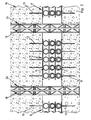
- FIG. 1 a composite structure for a tunnel called.
- the illustration shows the composite structure 1 seen from the tunnel longitudinal axis in the direction of the mountains.
- the composite structure 1 comprises a curved construction 2 from end-to-end channel profiles 3, which are clamped together in the overlapping area 4 by clamping means 5 which are not illustrated in greater detail, so that the channel profiles 3 can slide relative to one another at a correspondingly high rock pressure.
- the composite construction 1 further comprises a concrete shell applied to the mountains by means of shotcrete or shotcrete in which the gutter profiles 3 are also embedded.
- each compliance element 8 In a recessed area 7 of the concrete shell 6 are located next to the channel profiles 3 compliance elements 8. As in this context, the FIGS. 3 and 4 can be seen closer, each compliance element 8, a lower support plate 9 and an upper support plate 10. On the underside 11 of the lower support plate 9 and the top 12 of the upper support plate 10 reinforcing elements 13 are welded in the form of U-shaped bent wires, which, like the FIG. 1 can recognize, in the concrete shell 6 protrude.
- the support plates 9, 10 are connected in non-illustrated manner with the channel profiles 3.
- tubular body 16 In the height range between the two support plates 9, 10 are two separating plates 14, 15. Between the support plates 9, 10 and the separating plates 14, 15 are tubular body 16 is welded with a circular cross-section. Thus, three layers L, L1 and L2 are formed with tubular bodies 16. At the Embodiment, all tubular body 16 have the same diameter D and the same wall thickness WD. However, it is also conceivable that the diameter D and / or the wall thickness WD of the tubular bodies 16 vary from position L, L1 to position L1, L2.
- yielding element 8 is also in the composite construction 1a of FIG. 2 used. This differs from the Verbundausbau 1 of FIG. 1 only in that instead of the gutter profiles 3 lattice girders 18 are used as a sheet expansion 2a. Thus, on a further description of the FIG. 2 waived.
- the hollow profile 17a according to the FIGS. 5 and 6 consist of a slotted tube.
- the slotted hollow section 17a is widened so that it fits for insertion into the tubular body 16 according to FIG. 5 must be compressed. In the compressed state, it can then in the tubular body 16 according to FIG. 5 be pushed in, so that it ultimately according to the representation of the FIG. 7 is applied by spring force to the inner wall 19 of the tubular body 16 and thus properly clamped in the tubular body 16.
- FIGS. 8 and 9 are used to fix the position of a circumferentially closed hollow section 17 in a tubular body 16 spring wires 20.
- two spring wires 20 are stapled punctually in opposite arrangement to the inner surface 21 of a hollow section 17.
- the insertion direction ER of the hollow section 17 forward ends 22 of the spring wires 20 protrude beyond the end face 23 of the hollow section 17 and are according to FIG. 9 Bent V-shaped.
- rear ends 24 of the spring wires 20 are bent by almost 90 ° to the outside.
- spring steel bands 27 are used for fixing a circumferentially closed hollow section 17 in a tubular body 16 .
- These opposing spring steel strips 27 are first bent over two layers and inserted when inserting a hollow section 17 in a tubular body 16 in the gap 28 between the hollow section 17 and the tubular body 16 with.
- the spring steel strips 27 brace due to their inherent spring force the hollow section 17 in the tubular body 16.
- the spring steel bands 27 may be fixed selectively before the insertion of the hollow section 17 in the tubular body 16 on the outer surface 29 of the hollow section 17.
Landscapes
- Engineering & Computer Science (AREA)
- Mining & Mineral Resources (AREA)
- Architecture (AREA)
- Structural Engineering (AREA)
- Life Sciences & Earth Sciences (AREA)
- Civil Engineering (AREA)
- General Life Sciences & Earth Sciences (AREA)
- Geochemistry & Mineralogy (AREA)
- Geology (AREA)
- Mechanical Engineering (AREA)
- Lining And Supports For Tunnels (AREA)
- Tents Or Canopies (AREA)
- Bidet-Like Cleaning Device And Other Flush Toilet Accessories (AREA)
- Semiconductor Memories (AREA)
- Separation By Low-Temperature Treatments (AREA)
Claims (8)
- Elément de flexibilité conçu pour être intégré dans une structure composite souterraine (1, 1a) constituée d'une coque de béton (6) et de profilés rainurés (3) ou de supports en treillis (18), ledit élément comprenant au moins deux tôles de support (9, 10) disposées à distance l'une de l'autre, et plusieurs corps tubulaires (16) distants les uns des autres et prévus entre les tôles de support (9, 10), sachant que lesdites tôles de support (9, 10), pouvant être verrouillées à demeure sur les profilés rainurés (3) ou sur les supports en treillis (18), sont pourvues d'armatures (13) pénétrant dans la coque de béton (6), caractérisé par le fait qu'au moins un profilé creux (17, 17a) est intégré dans au moins un corps tubulaire (16).
- Elément de flexibilité selon la revendication 1, caractérisé par le fait que le profilé creux (17, 17a) est bloqué à demeure dans le corps tubulaire (16).
- Elément de flexibilité selon la revendication 1 ou 2, caractérisé par le fait que le profilé creux (17a) est constitué d'un tube fendu emmanché dans le corps tubulaire (16), par frottement et par concordance de formes.
- Elément de flexibilité selon la revendication 1 ou 2, caractérisé par le fait que le profilé creux (17) est constitué d'un tube à pourtour fermé, coincé dans le corps tubulaire (16) au moyen d'éléments de fixation (20, 27).
- Elément de flexibilité selon la revendication 4, caractérisé par le fait que les éléments de fixation (20) se présentent comme des fils métalliques verrouillés à demeure dans le profilé creux (17).
- Elément de flexibilité selon la revendication 4, caractérisé par le fait que les éléments de fixation (27) se présentent comme des rubans (27) en acier à ressorts, pouvant être insérés entre le corps tubulaire (16) et le profilé creux (17).
- Elément de flexibilité selon l'une des revendications 1 à 6, caractérisé par la présence, entre les tôles de support (9, 10), d'au moins deux couches (L, L1, L2) composées de corps tubulaires (16) et de profilés creux (17, 17a) intégrés dans ces derniers, une tôle de séparation (14, 15) étant interposée entre deux couches (L, L1 ; L1, L2).
- Elément de flexibilité selon la revendication 7, caractérisé par le fait que les corps tubulaires (16) et/ou les profilés creux (17, 17a) situés dans une couche (L, L1, L2) présentent, comparativement aux corps tubulaires (16) et/ou aux profilés creux (17, 17a) situés dans une autre couche (L1, L2), des épaisseurs de parois (WD, WD1, WD2) et/ou des diamètres (D) qui diffèrent les un(e)s des autres.
Priority Applications (4)
| Application Number | Priority Date | Filing Date | Title |
|---|---|---|---|
| DE502007001042T DE502007001042D1 (de) | 2007-09-27 | 2007-09-27 | Nachgiebigkeitselement |
| AT07019019T ATE435965T1 (de) | 2007-09-27 | 2007-09-27 | Nachgiebigkeitselement |
| EP07019019A EP2042686B1 (fr) | 2007-09-27 | 2007-09-27 | Elément de flexibilité |
| AU2008229738A AU2008229738B2 (en) | 2007-09-27 | 2008-09-26 | Yielding element |
Applications Claiming Priority (1)
| Application Number | Priority Date | Filing Date | Title |
|---|---|---|---|
| EP07019019A EP2042686B1 (fr) | 2007-09-27 | 2007-09-27 | Elément de flexibilité |
Publications (2)
| Publication Number | Publication Date |
|---|---|
| EP2042686A1 EP2042686A1 (fr) | 2009-04-01 |
| EP2042686B1 true EP2042686B1 (fr) | 2009-07-08 |
Family
ID=39078488
Family Applications (1)
| Application Number | Title | Priority Date | Filing Date |
|---|---|---|---|
| EP07019019A Active EP2042686B1 (fr) | 2007-09-27 | 2007-09-27 | Elément de flexibilité |
Country Status (4)
| Country | Link |
|---|---|
| EP (1) | EP2042686B1 (fr) |
| AT (1) | ATE435965T1 (fr) |
| AU (1) | AU2008229738B2 (fr) |
| DE (1) | DE502007001042D1 (fr) |
Cited By (4)
| Publication number | Priority date | Publication date | Assignee | Title |
|---|---|---|---|---|
| WO2011069480A2 (fr) | 2009-12-10 | 2011-06-16 | Bochumer Eisenhütte Heintzmann GmbH & Co. KG | Cuvelage à élément élastique intégré |
| DE202014000435U1 (de) | 2013-12-27 | 2015-04-01 | Sz Schacht- Und Streckenausbau Gmbh | Nachgiebigkeitselement |
| DE102014000594A1 (de) | 2013-12-27 | 2015-07-02 | Sz Schacht- Und Streckenausbau Gmbh | Nachgiebigkeitselement |
| EP2918772A2 (fr) | 2014-03-14 | 2015-09-16 | Bochumer Eisenhütte Heintzmann GmbH&Co. Kg | Système d'aménagement pour tunnel ou voies souterraines |
Families Citing this family (8)
| Publication number | Priority date | Publication date | Assignee | Title |
|---|---|---|---|---|
| EP2834462B1 (fr) * | 2012-04-03 | 2018-08-01 | Constructions Mécaniques Consultants | Système et procédé d'amortissement de la convergence d'un terrain, procédé de fabrication d'un tel système |
| FR2988770B1 (fr) * | 2012-04-03 | 2014-04-25 | Assistance Et Conseil Ind | Systeme et procede d'amortissement de la convergence d'un terrain |
| FR3012513B1 (fr) * | 2013-10-31 | 2016-10-14 | Constructions Mec Consultants | Dispositif et systeme d'amortissement de la convergence d'un terrain, procedes de fabrication de tels dispositif et systeme |
| CN103573273B (zh) * | 2013-11-14 | 2015-08-26 | 山东科技大学 | 沿空留巷巷旁柔强双层复合支护高强材料适宜性评价方法 |
| DE102017008627A1 (de) * | 2017-09-14 | 2019-03-14 | Sz Schacht- Und Streckenausbau Gmbh | Nachgiebigkeitselement |
| CN107780951B (zh) * | 2017-11-01 | 2024-03-01 | 中交第一公路勘察设计研究院有限公司 | 高地应力软岩大变形初期支护体系 |
| CN109339817B (zh) * | 2018-08-30 | 2020-07-03 | 上海隧道工程有限公司 | 用于机械法联络通道曲面管片的切削控制方法 |
| CN113530560A (zh) * | 2021-07-16 | 2021-10-22 | 中国建筑第六工程局有限公司 | 一种先盾后井的管廊施工方法 |
Family Cites Families (6)
| Publication number | Priority date | Publication date | Assignee | Title |
|---|---|---|---|---|
| DE3210530C2 (de) * | 1982-03-23 | 1984-01-05 | Bergwerksverband Gmbh, 4300 Essen | Nachgiebiger Betonsegmentausbau |
| DE4221656A1 (de) * | 1992-02-18 | 1993-08-19 | Voss Kurt Heinz Dipl Berging | Nachgiebige hinterfuellung fuer den streckenausbau im bergbau |
| US5992118A (en) * | 1995-09-29 | 1999-11-30 | Git Tunnelbau Gmbh | Segment for lining cavities |
| AT406893B (de) * | 1997-11-28 | 2000-10-25 | Schubert Wulf Dipl Ing Dr | Vorrichtung zum gegenseitigen abstützen zweier segmente einer in umfangsrichtung durch kontraktionsfugen unterteilten tunnelauskleidung |
| ATE380925T1 (de) * | 2004-02-16 | 2007-12-15 | Kalman Kovari | Verfahren und einrichtung zum stabilisieren eines beim untertagebau ausgebrochenen hohlraumes |
| DE502005006010D1 (de) * | 2005-09-08 | 2009-01-02 | Amberg Engineering Ag | Nachgiebigkeitselement für einen Untertageraum |
-
2007
- 2007-09-27 EP EP07019019A patent/EP2042686B1/fr active Active
- 2007-09-27 DE DE502007001042T patent/DE502007001042D1/de active Active
- 2007-09-27 AT AT07019019T patent/ATE435965T1/de active
-
2008
- 2008-09-26 AU AU2008229738A patent/AU2008229738B2/en not_active Ceased
Cited By (8)
| Publication number | Priority date | Publication date | Assignee | Title |
|---|---|---|---|---|
| WO2011069480A2 (fr) | 2009-12-10 | 2011-06-16 | Bochumer Eisenhütte Heintzmann GmbH & Co. KG | Cuvelage à élément élastique intégré |
| DE102009057521A1 (de) | 2009-12-10 | 2011-06-16 | Bochumer Eisenhütte Heintzmann GmbH & Co. KG | Tübbing-Ausbau mit integriertem Nachgiebigkeitselement |
| DE102009057521B4 (de) * | 2009-12-10 | 2011-07-21 | Bochumer Eisenhütte Heintzmann GmbH & Co. KG, 44793 | Tübbing-Ausbau mit integriertem Nachgiebigkeitselement |
| DE202014000435U1 (de) | 2013-12-27 | 2015-04-01 | Sz Schacht- Und Streckenausbau Gmbh | Nachgiebigkeitselement |
| DE102014000594A1 (de) | 2013-12-27 | 2015-07-02 | Sz Schacht- Und Streckenausbau Gmbh | Nachgiebigkeitselement |
| DE102014000594B4 (de) * | 2013-12-27 | 2015-12-31 | Sz Schacht- Und Streckenausbau Gmbh | Nachgiebigkeitselement |
| EP2918772A2 (fr) | 2014-03-14 | 2015-09-16 | Bochumer Eisenhütte Heintzmann GmbH&Co. Kg | Système d'aménagement pour tunnel ou voies souterraines |
| DE102014103477A1 (de) | 2014-03-14 | 2015-09-17 | Bochumer Eisenhütte Heintzmann GmbH & Co. KG | Ausbausystem für untertägige Tunnel oder Strecken, Ausbaueinheit sowie Bogensegment |
Also Published As
| Publication number | Publication date |
|---|---|
| ATE435965T1 (de) | 2009-07-15 |
| AU2008229738A1 (en) | 2009-04-23 |
| EP2042686A1 (fr) | 2009-04-01 |
| DE502007001042D1 (de) | 2009-08-20 |
| AU2008229738B2 (en) | 2010-05-27 |
Similar Documents
| Publication | Publication Date | Title |
|---|---|---|
| EP2042686B1 (fr) | Elément de flexibilité | |
| DE102004050300B4 (de) | Profilschelle | |
| EP2918772A2 (fr) | Système d'aménagement pour tunnel ou voies souterraines | |
| EP2631392A1 (fr) | Dispositif d'introduction de force dans des éléments de traction à partir de lamelles de bandes plates en matière synthétique renforcées en fibres | |
| EP1762698B1 (fr) | Elément souple pour une cavité souterraine | |
| DE3012613C2 (de) | Ankerausbau für Strecken des untertägigen Bergbaus, Tunnel o.dgl. | |
| DE3023411A1 (de) | Spreizanker | |
| EP2520728A1 (fr) | Module encastrable et procédé de montage d'une introduction de lignes d'un dispositif de drainage | |
| DE4418937C2 (de) | Klappgelenkmatte | |
| DE3243852A1 (de) | Verbundausbau | |
| DE102014000594B4 (de) | Nachgiebigkeitselement | |
| EP2080841B1 (fr) | Elément de pose de dalles en console | |
| EP1701002A1 (fr) | Dispositif avec une cage pour un cuvelage en béton armé | |
| EP0182777B1 (fr) | Clou | |
| DE3017428A1 (de) | Streckenausbau des berg- und tunnelbaus | |
| DE3116850A1 (de) | Spreizhuelse fuer bauwerksteile | |
| EP1688545A1 (fr) | Ancrage d'injection ou précontrainte pour la construction en surface et la construction souterraine | |
| DE102011001894A1 (de) | Verfahren zur Herstellung einer Spreizhülse, Spreizhülse und Baureihe von Spreizhülsen | |
| DE4003678C2 (fr) | ||
| DE102009049178A1 (de) | Schalung | |
| EP2090703B1 (fr) | Dormant pour la réception d'un recouvrement | |
| DE2554899C3 (de) | Nachgiebiger Streckenausbau aus Stahl | |
| DE2515166B1 (de) | Spannverbindung fuer ineinander liegende enden bodenabgestuetzter rinnenprofile von grubenausbaurahmen | |
| CH420024A (de) | Formkörper zum Bilden einer gelochten Hülse oder eines gelochten Rohres | |
| CH709036A2 (de) | Nachgiebigkeitselement zur Integration in einem untertägigen Verbundausbau. |
Legal Events
| Date | Code | Title | Description |
|---|---|---|---|
| GRAP | Despatch of communication of intention to grant a patent |
Free format text: ORIGINAL CODE: EPIDOSNIGR1 |
|
| GRAS | Grant fee paid |
Free format text: ORIGINAL CODE: EPIDOSNIGR3 |
|
| PUAI | Public reference made under article 153(3) epc to a published international application that has entered the european phase |
Free format text: ORIGINAL CODE: 0009012 |
|
| 17P | Request for examination filed |
Effective date: 20080402 |
|
| AK | Designated contracting states |
Kind code of ref document: A1 Designated state(s): AT BE BG CH CY CZ DE DK EE ES FI FR GB GR HU IE IS IT LI LT LU LV MC MT NL PL PT RO SE SI SK TR |
|
| AX | Request for extension of the european patent |
Extension state: AL BA HR MK RS |
|
| GRAA | (expected) grant |
Free format text: ORIGINAL CODE: 0009210 |
|
| AK | Designated contracting states |
Kind code of ref document: B1 Designated state(s): AT BE BG CH CY CZ DE DK EE ES FI FR GB GR HU IE IS IT LI LT LU LV MC MT NL PL PT RO SE SI SK TR |
|
| AX | Request for extension of the european patent |
Extension state: BA |
|
| REG | Reference to a national code |
Ref country code: GB Ref legal event code: FG4D Free format text: NOT ENGLISH |
|
| REG | Reference to a national code |
Ref country code: CH Ref legal event code: EP |
|
| REG | Reference to a national code |
Ref country code: IE Ref legal event code: FG4D |
|
| REF | Corresponds to: |
Ref document number: 502007001042 Country of ref document: DE Date of ref document: 20090820 Kind code of ref document: P |
|
| REG | Reference to a national code |
Ref country code: CH Ref legal event code: NV Representative=s name: PATENTANWAELTE SCHAAD, BALASS, MENZL & PARTNER AG |
|
| REG | Reference to a national code |
Ref country code: GR Ref legal event code: EP Ref document number: 20090402249 Country of ref document: GR |
|
| PG25 | Lapsed in a contracting state [announced via postgrant information from national office to epo] |
Ref country code: SI Free format text: LAPSE BECAUSE OF FAILURE TO SUBMIT A TRANSLATION OF THE DESCRIPTION OR TO PAY THE FEE WITHIN THE PRESCRIBED TIME-LIMIT Effective date: 20090708 |
|
| NLV1 | Nl: lapsed or annulled due to failure to fulfill the requirements of art. 29p and 29m of the patents act | ||
| AKX | Designation fees paid |
Designated state(s): AT BE BG CH CY CZ DE DK EE ES FI FR GB GR HU IE IS IT LI LT LU LV MC MT NL PL PT RO SE SI SK TR |
|
| AXX | Extension fees paid |
Extension state: BA Payment date: 20080807 |
|
| PG25 | Lapsed in a contracting state [announced via postgrant information from national office to epo] |
Ref country code: ES Free format text: LAPSE BECAUSE OF FAILURE TO SUBMIT A TRANSLATION OF THE DESCRIPTION OR TO PAY THE FEE WITHIN THE PRESCRIBED TIME-LIMIT Effective date: 20091019 Ref country code: LT Free format text: LAPSE BECAUSE OF FAILURE TO SUBMIT A TRANSLATION OF THE DESCRIPTION OR TO PAY THE FEE WITHIN THE PRESCRIBED TIME-LIMIT Effective date: 20090708 Ref country code: IS Free format text: LAPSE BECAUSE OF FAILURE TO SUBMIT A TRANSLATION OF THE DESCRIPTION OR TO PAY THE FEE WITHIN THE PRESCRIBED TIME-LIMIT Effective date: 20091108 Ref country code: FI Free format text: LAPSE BECAUSE OF FAILURE TO SUBMIT A TRANSLATION OF THE DESCRIPTION OR TO PAY THE FEE WITHIN THE PRESCRIBED TIME-LIMIT Effective date: 20090708 |
|
| REG | Reference to a national code |
Ref country code: IE Ref legal event code: FD4D |
|
| PG25 | Lapsed in a contracting state [announced via postgrant information from national office to epo] |
Ref country code: NL Free format text: LAPSE BECAUSE OF FAILURE TO SUBMIT A TRANSLATION OF THE DESCRIPTION OR TO PAY THE FEE WITHIN THE PRESCRIBED TIME-LIMIT Effective date: 20090708 Ref country code: PL Free format text: LAPSE BECAUSE OF FAILURE TO SUBMIT A TRANSLATION OF THE DESCRIPTION OR TO PAY THE FEE WITHIN THE PRESCRIBED TIME-LIMIT Effective date: 20090708 Ref country code: LV Free format text: LAPSE BECAUSE OF FAILURE TO SUBMIT A TRANSLATION OF THE DESCRIPTION OR TO PAY THE FEE WITHIN THE PRESCRIBED TIME-LIMIT Effective date: 20090708 |
|
| BERE | Be: lapsed |
Owner name: BOCHUMER EISENHUTTE HEINTZMANN G.M.B.H. & CO. KG Effective date: 20090930 |
|
| PG25 | Lapsed in a contracting state [announced via postgrant information from national office to epo] |
Ref country code: BG Free format text: LAPSE BECAUSE OF FAILURE TO SUBMIT A TRANSLATION OF THE DESCRIPTION OR TO PAY THE FEE WITHIN THE PRESCRIBED TIME-LIMIT Effective date: 20091008 Ref country code: PT Free format text: LAPSE BECAUSE OF FAILURE TO SUBMIT A TRANSLATION OF THE DESCRIPTION OR TO PAY THE FEE WITHIN THE PRESCRIBED TIME-LIMIT Effective date: 20091109 |
|
| PG25 | Lapsed in a contracting state [announced via postgrant information from national office to epo] |
Ref country code: RO Free format text: LAPSE BECAUSE OF FAILURE TO SUBMIT A TRANSLATION OF THE DESCRIPTION OR TO PAY THE FEE WITHIN THE PRESCRIBED TIME-LIMIT Effective date: 20090708 Ref country code: MC Free format text: LAPSE BECAUSE OF NON-PAYMENT OF DUE FEES Effective date: 20090930 Ref country code: DK Free format text: LAPSE BECAUSE OF FAILURE TO SUBMIT A TRANSLATION OF THE DESCRIPTION OR TO PAY THE FEE WITHIN THE PRESCRIBED TIME-LIMIT Effective date: 20090708 Ref country code: CZ Free format text: LAPSE BECAUSE OF FAILURE TO SUBMIT A TRANSLATION OF THE DESCRIPTION OR TO PAY THE FEE WITHIN THE PRESCRIBED TIME-LIMIT Effective date: 20090708 Ref country code: EE Free format text: LAPSE BECAUSE OF FAILURE TO SUBMIT A TRANSLATION OF THE DESCRIPTION OR TO PAY THE FEE WITHIN THE PRESCRIBED TIME-LIMIT Effective date: 20090708 Ref country code: IE Free format text: LAPSE BECAUSE OF FAILURE TO SUBMIT A TRANSLATION OF THE DESCRIPTION OR TO PAY THE FEE WITHIN THE PRESCRIBED TIME-LIMIT Effective date: 20090708 |
|
| PLBE | No opposition filed within time limit |
Free format text: ORIGINAL CODE: 0009261 |
|
| STAA | Information on the status of an ep patent application or granted ep patent |
Free format text: STATUS: NO OPPOSITION FILED WITHIN TIME LIMIT |
|
| PG25 | Lapsed in a contracting state [announced via postgrant information from national office to epo] |
Ref country code: SK Free format text: LAPSE BECAUSE OF FAILURE TO SUBMIT A TRANSLATION OF THE DESCRIPTION OR TO PAY THE FEE WITHIN THE PRESCRIBED TIME-LIMIT Effective date: 20090708 |
|
| 26N | No opposition filed |
Effective date: 20100409 |
|
| PG25 | Lapsed in a contracting state [announced via postgrant information from national office to epo] |
Ref country code: BE Free format text: LAPSE BECAUSE OF NON-PAYMENT OF DUE FEES Effective date: 20090930 |
|
| PG25 | Lapsed in a contracting state [announced via postgrant information from national office to epo] |
Ref country code: IT Free format text: LAPSE BECAUSE OF FAILURE TO SUBMIT A TRANSLATION OF THE DESCRIPTION OR TO PAY THE FEE WITHIN THE PRESCRIBED TIME-LIMIT Effective date: 20090708 |
|
| PG25 | Lapsed in a contracting state [announced via postgrant information from national office to epo] |
Ref country code: MT Free format text: LAPSE BECAUSE OF FAILURE TO SUBMIT A TRANSLATION OF THE DESCRIPTION OR TO PAY THE FEE WITHIN THE PRESCRIBED TIME-LIMIT Effective date: 20090708 |
|
| PG25 | Lapsed in a contracting state [announced via postgrant information from national office to epo] |
Ref country code: HU Free format text: LAPSE BECAUSE OF FAILURE TO SUBMIT A TRANSLATION OF THE DESCRIPTION OR TO PAY THE FEE WITHIN THE PRESCRIBED TIME-LIMIT Effective date: 20100109 |
|
| PG25 | Lapsed in a contracting state [announced via postgrant information from national office to epo] |
Ref country code: TR Free format text: LAPSE BECAUSE OF FAILURE TO SUBMIT A TRANSLATION OF THE DESCRIPTION OR TO PAY THE FEE WITHIN THE PRESCRIBED TIME-LIMIT Effective date: 20090708 |
|
| PG25 | Lapsed in a contracting state [announced via postgrant information from national office to epo] |
Ref country code: CY Free format text: LAPSE BECAUSE OF FAILURE TO SUBMIT A TRANSLATION OF THE DESCRIPTION OR TO PAY THE FEE WITHIN THE PRESCRIBED TIME-LIMIT Effective date: 20090708 |
|
| GBPC | Gb: european patent ceased through non-payment of renewal fee |
Effective date: 20110927 |
|
| PG25 | Lapsed in a contracting state [announced via postgrant information from national office to epo] |
Ref country code: GB Free format text: LAPSE BECAUSE OF NON-PAYMENT OF DUE FEES Effective date: 20110927 |
|
| PG25 | Lapsed in a contracting state [announced via postgrant information from national office to epo] |
Ref country code: SE Free format text: LAPSE BECAUSE OF FAILURE TO SUBMIT A TRANSLATION OF THE DESCRIPTION OR TO PAY THE FEE WITHIN THE PRESCRIBED TIME-LIMIT Effective date: 20090708 |
|
| REG | Reference to a national code |
Ref country code: FR Ref legal event code: PLFP Year of fee payment: 9 |
|
| REG | Reference to a national code |
Ref country code: FR Ref legal event code: PLFP Year of fee payment: 10 |
|
| REG | Reference to a national code |
Ref country code: FR Ref legal event code: PLFP Year of fee payment: 11 |
|
| PGFP | Annual fee paid to national office [announced via postgrant information from national office to epo] |
Ref country code: ES Payment date: 20170830 Year of fee payment: 11 Ref country code: LU Payment date: 20170921 Year of fee payment: 11 |
|
| REG | Reference to a national code |
Ref country code: FR Ref legal event code: PLFP Year of fee payment: 12 |
|
| PG25 | Lapsed in a contracting state [announced via postgrant information from national office to epo] |
Ref country code: LU Free format text: LAPSE BECAUSE OF NON-PAYMENT OF DUE FEES Effective date: 20180927 |
|
| PG25 | Lapsed in a contracting state [announced via postgrant information from national office to epo] |
Ref country code: GR Free format text: LAPSE BECAUSE OF NON-PAYMENT OF DUE FEES Effective date: 20190402 |
|
| PGFP | Annual fee paid to national office [announced via postgrant information from national office to epo] |
Ref country code: AT Payment date: 20230921 Year of fee payment: 17 |
|
| PGFP | Annual fee paid to national office [announced via postgrant information from national office to epo] |
Ref country code: FR Payment date: 20230928 Year of fee payment: 17 Ref country code: DE Payment date: 20230928 Year of fee payment: 17 |
|
| PGFP | Annual fee paid to national office [announced via postgrant information from national office to epo] |
Ref country code: CH Payment date: 20231001 Year of fee payment: 17 |