EP2042686B1 - Nachgiebigkeitselement - Google Patents
Nachgiebigkeitselement Download PDFInfo
- Publication number
- EP2042686B1 EP2042686B1 EP07019019A EP07019019A EP2042686B1 EP 2042686 B1 EP2042686 B1 EP 2042686B1 EP 07019019 A EP07019019 A EP 07019019A EP 07019019 A EP07019019 A EP 07019019A EP 2042686 B1 EP2042686 B1 EP 2042686B1
- Authority
- EP
- European Patent Office
- Prior art keywords
- tubular body
- hollow
- hollow profile
- element according
- tubular
- Prior art date
- Legal status (The legal status is an assumption and is not a legal conclusion. Google has not performed a legal analysis and makes no representation as to the accuracy of the status listed.)
- Active
Links
- 239000004567 concrete Substances 0.000 claims abstract description 10
- 230000002787 reinforcement Effects 0.000 claims abstract description 4
- 229910000639 Spring steel Inorganic materials 0.000 claims description 9
- 150000001875 compounds Chemical class 0.000 claims 1
- 230000002093 peripheral effect Effects 0.000 abstract 1
- 239000002131 composite material Substances 0.000 description 13
- 238000003780 insertion Methods 0.000 description 10
- 230000037431 insertion Effects 0.000 description 10
- 238000010276 construction Methods 0.000 description 9
- 239000011378 shotcrete Substances 0.000 description 4
- 230000006835 compression Effects 0.000 description 3
- 238000007906 compression Methods 0.000 description 3
- 239000011435 rock Substances 0.000 description 3
- 230000010354 integration Effects 0.000 description 2
- 230000003014 reinforcing effect Effects 0.000 description 1
- 125000006850 spacer group Chemical group 0.000 description 1
- 238000003466 welding Methods 0.000 description 1
Images


Classifications
-
- E—FIXED CONSTRUCTIONS
- E21—EARTH OR ROCK DRILLING; MINING
- E21D—SHAFTS; TUNNELS; GALLERIES; LARGE UNDERGROUND CHAMBERS
- E21D11/00—Lining tunnels, galleries or other underground cavities, e.g. large underground chambers; Linings therefor; Making such linings in situ, e.g. by assembling
- E21D11/04—Lining with building materials
- E21D11/05—Lining with building materials using compressible insertions
-
- E—FIXED CONSTRUCTIONS
- E21—EARTH OR ROCK DRILLING; MINING
- E21D—SHAFTS; TUNNELS; GALLERIES; LARGE UNDERGROUND CHAMBERS
- E21D11/00—Lining tunnels, galleries or other underground cavities, e.g. large underground chambers; Linings therefor; Making such linings in situ, e.g. by assembling
- E21D11/04—Lining with building materials
- E21D11/08—Lining with building materials with preformed concrete slabs
-
- E—FIXED CONSTRUCTIONS
- E21—EARTH OR ROCK DRILLING; MINING
- E21D—SHAFTS; TUNNELS; GALLERIES; LARGE UNDERGROUND CHAMBERS
- E21D11/00—Lining tunnels, galleries or other underground cavities, e.g. large underground chambers; Linings therefor; Making such linings in situ, e.g. by assembling
- E21D11/14—Lining predominantly with metal
- E21D11/18—Arch members ; Network made of arch members ; Ring elements; Polygon elements; Polygon elements inside arches
Definitions
- the invention relates to a compliance element for integration in an underground composite construction of channel profiles or lattice girders and a concrete shell according to the features in the preamble of claim 1.
- a compliance element is basically within the scope of EP 1 762 698 A1 known. It is used in the construction of elongated underground structures such as tunnels or tunnels.
- the compliance element is designed so that it can be compressed under the influence of rock pressure. It is honeycomb-shaped and has intermediate layers and spacers which form gaps. The gaps are offset from each other and are reduced when compressed.
- the gutter profiles or lattice girders are embedded by means of shotcrete or shotcrete in a concrete shell inserted on the circumference of the tunnel or the track.
- the known compliance element has basically proven itself in practice. For example, during the construction phase of a tunnel or a route, the person skilled in the art can already see which force from the mountain acts on the composite structure. In particular, however, which force rests on the compliance element. Consequently, a compliance element is mainly used in fault zones or in a pressure rock. The number of each to be integrated in a composite expansion compliance elements depends on the local conditions.
- the invention is - based on the prior art - the object to provide a compliance element for integration into an underground composite structure, which has an increased resistance to the force from the mountains.
- At least one hollow profile is now inserted into at least one tubular body of a compliance element.
- a hollow profile is inserted or whether only in selected tubular bodies hollow sections are provided or whether more than one hollow section is used in a tubular body depends on the local Conditions from. In this case, it is conceivable for the person skilled in the art to insert hollow sections into the tubular body as needed on site. If the local conditions are already known in advance, then the compliance elements can already be appropriately prepared at the factory and provided in a suitable manner with hollow profiles in the tubular bodies.
- the hollow profile is suitably fixed in position in the tubular body according to claim 2. In this way, it keeps its intended position until the composite construction is completed in its entirety.
- the hollow profile consists of a slot tube which is frictionally and positively pressed into the tubular body.
- the hollow profile can also consist of a circumferentially closed tube with preferably circular cross-section, which is clamped by means of fastening elements in the tubular body. But there are also other cross-sections of a hollow profile conceivable.
- the fastening elements consist of fixed in the hollow profile wires.
- two wires such as welding wires, dotted and provided on the opposite ends of the protruding ends with bent legs, wherein the forward leg in the insertion direction are bent by about 160 °, so that they when inserting a hollow profile in a Tube bodies are compressed and slide on the inner wall of the tubular body.
- the legs in the insertion direction are bent by about 90 °. If these legs contact the rear end wall of the tubular body, the legs lying in the direction of insertion are exposed in front of the end face of the tubular body and can spring open, so that the hollow profile is then fixed in position over the legs in the longitudinal direction of the tubular body.
- fasteners consist of insertable between the tubular body and the hollow profile spring steel strips.
- two spring steel strips which are preferably provided in an opposing arrangement, are also bent in two layers and inserted into the gap between the hollow profile and the tubular body.
- inserting the hollow profile in the tubular body slide the spring steel strips in the tubular body and ultimately tense due to the inherent spreading force in the use position, the hollow section in the tubular body.
- a particularly advantageous embodiment of the invention according to claim 7 is that between the support plates at least two layers are provided with tubular bodies and hollow sections inserted therein, wherein between two layers, a separating plate is arranged.
- the number of tube body layers and separating plates required depends on the respective local conditions. For example, three or four layers are conceivable. Also, the number of tubular body with hollow profiles in the individual layers may vary from application point to application point.
- the tube body and / or the hollow profiles in a position compared to the tubular bodies and / or the hollow sections in a different position have different wall thicknesses and / or diameter.
- the upper layer does not provide hollow sections in the tubular bodies, the middle and lower layers but have hollow sections in the tubular bodies, but the wall thicknesses of the hollow profiles in the lower layer are greater than that of the Hollow profiles in the tubular bodies of the middle layer.
- the wall thickness can be varied within the scope of the invention with different diameters of the hollow profiles.
- a combination of the diameter of the tubular body and its wall thicknesses with the diameters and / or Wall thickness of the hollow sections done.
- the number of hollow sections in the tubular bodies may vary from one point of use to another.
- a controlled compliance behavior can be achieved, wherein the carrying capacity of a compliance element can be exactly matched to that of the adjacent channel profiles or lattice girders.
- the compliance element also begins to deform and absorb load.
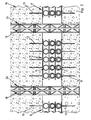
- FIG. 1 a composite structure for a tunnel called.
- the illustration shows the composite structure 1 seen from the tunnel longitudinal axis in the direction of the mountains.
- the composite structure 1 comprises a curved construction 2 from end-to-end channel profiles 3, which are clamped together in the overlapping area 4 by clamping means 5 which are not illustrated in greater detail, so that the channel profiles 3 can slide relative to one another at a correspondingly high rock pressure.
- the composite construction 1 further comprises a concrete shell applied to the mountains by means of shotcrete or shotcrete in which the gutter profiles 3 are also embedded.
- each compliance element 8 In a recessed area 7 of the concrete shell 6 are located next to the channel profiles 3 compliance elements 8. As in this context, the FIGS. 3 and 4 can be seen closer, each compliance element 8, a lower support plate 9 and an upper support plate 10. On the underside 11 of the lower support plate 9 and the top 12 of the upper support plate 10 reinforcing elements 13 are welded in the form of U-shaped bent wires, which, like the FIG. 1 can recognize, in the concrete shell 6 protrude.
- the support plates 9, 10 are connected in non-illustrated manner with the channel profiles 3.
- tubular body 16 In the height range between the two support plates 9, 10 are two separating plates 14, 15. Between the support plates 9, 10 and the separating plates 14, 15 are tubular body 16 is welded with a circular cross-section. Thus, three layers L, L1 and L2 are formed with tubular bodies 16. At the Embodiment, all tubular body 16 have the same diameter D and the same wall thickness WD. However, it is also conceivable that the diameter D and / or the wall thickness WD of the tubular bodies 16 vary from position L, L1 to position L1, L2.
- yielding element 8 is also in the composite construction 1a of FIG. 2 used. This differs from the Verbundausbau 1 of FIG. 1 only in that instead of the gutter profiles 3 lattice girders 18 are used as a sheet expansion 2a. Thus, on a further description of the FIG. 2 waived.
- the hollow profile 17a according to the FIGS. 5 and 6 consist of a slotted tube.
- the slotted hollow section 17a is widened so that it fits for insertion into the tubular body 16 according to FIG. 5 must be compressed. In the compressed state, it can then in the tubular body 16 according to FIG. 5 be pushed in, so that it ultimately according to the representation of the FIG. 7 is applied by spring force to the inner wall 19 of the tubular body 16 and thus properly clamped in the tubular body 16.
- FIGS. 8 and 9 are used to fix the position of a circumferentially closed hollow section 17 in a tubular body 16 spring wires 20.
- two spring wires 20 are stapled punctually in opposite arrangement to the inner surface 21 of a hollow section 17.
- the insertion direction ER of the hollow section 17 forward ends 22 of the spring wires 20 protrude beyond the end face 23 of the hollow section 17 and are according to FIG. 9 Bent V-shaped.
- rear ends 24 of the spring wires 20 are bent by almost 90 ° to the outside.
- spring steel bands 27 are used for fixing a circumferentially closed hollow section 17 in a tubular body 16 .
- These opposing spring steel strips 27 are first bent over two layers and inserted when inserting a hollow section 17 in a tubular body 16 in the gap 28 between the hollow section 17 and the tubular body 16 with.
- the spring steel strips 27 brace due to their inherent spring force the hollow section 17 in the tubular body 16.
- the spring steel bands 27 may be fixed selectively before the insertion of the hollow section 17 in the tubular body 16 on the outer surface 29 of the hollow section 17.
Landscapes
- Engineering & Computer Science (AREA)
- Mining & Mineral Resources (AREA)
- Architecture (AREA)
- Structural Engineering (AREA)
- Life Sciences & Earth Sciences (AREA)
- Civil Engineering (AREA)
- General Life Sciences & Earth Sciences (AREA)
- Geochemistry & Mineralogy (AREA)
- Geology (AREA)
- Mechanical Engineering (AREA)
- Lining And Supports For Tunnels (AREA)
- Bidet-Like Cleaning Device And Other Flush Toilet Accessories (AREA)
- Semiconductor Memories (AREA)
- Separation By Low-Temperature Treatments (AREA)
- Tents Or Canopies (AREA)
Description
- Die Erfindung betrifft ein Nachgiebigkeitselement zur Integration in einen untertägigen Verbundausbau aus Rinnenprofilen oder Gitterträgern und einer Betonschale gemäß den Merkmalen im Oberbegriff des Anspruchs 1.
- Ein Nachgiebigkeitselement ist grundsätzlich im Umfang der
EP 1 762 698 A1 bekannt. Es wird beim Ausbau lang gestreckter Untertageräume, wie zum Beispiel Strecken oder Tunnel, eingesetzt. Das Nachgiebigkeitselement ist so ausgebildet, dass es unter dem Einfluss des Gebirgsdrucks zusammengedrückt werden kann. Es ist wabenförmig ausgebildet und weist Zwischenlagen und Abstandselemente auf, die Lücken bilden. Die Lücken sind zueinander versetzt und werden beim Zusammendrücken verkleinert. - Eine Weiterbildung des Nachgiebigkeitselements der
EP 1 762 698 A1 ist im Umfang des Prospekts "Stauchelement" der Bochumer Eisenhütte Heintzmann GmbH & Co. KG bekannt. Dieses Stauchelement umfasst mindestens zwei im Abstand zueinander angeordnete Tragbleche und mehrere zwischen den Tragblechen vorgesehene, zueinander distanzierte Rohrkörper. Ein solches Stauchelement wird vorwiegend zwischen zwei Bogenausbauen aus nachgiebigen Rinnenprofilen oder Gitterträgern eingesetzt. Ferner kann es hinter solchen Bogenausbauen zum Gebirgsmantel hin vorgesehen werden. Jeweils das obere und untere Tragblech weisen Befestigungselemente auf, die der Montage am Bogenausbau dienen. Darüber hinaus besitzen die Tragbleche in die Betonschale fassende Bewehrungen. - Die Rinnenprofile oder Gitterträger werden mittels Ort- oder Spritzbeton in eine umfangsseitig des Tunnels oder der Strecke eingebrachte Betonschale eingebettet.
- Das bekannte Nachgiebigkeitselement hat sich in der Praxis grundsätzlich bewährt. Der Fachmann kann beispielsweise schon während der Bauphase eines Tunnels oder einer Strecke erkennen, welche Kraft aus dem Gebirge auf den Verbundausbau wirkt. Insbesondere jedoch, welche Kraft auf dem Nachgiebigkeitselement lastet. Demzufolge kommt ein Nachgiebigkeitselement vorwiegend in Störungszonen oder bei einem druckhaften Gebirge zum Einsatz. Die Anzahl der jeweils in einen Verbundausbau zu integrierenden Nachgiebigkeitselemente hängt von den örtlichen Gegebenheiten ab.
- Die Dokumente
WO 99/28162 DE 4 221 656 A1 offenbaren weitere Nachgiebigkeitselemente. - Der Erfindung liegt - ausgehend vom Stand der Technik - die Aufgabe zu Grunde, ein Nachgiebigkeitselement zur Integration in einen untertägigen Verbundausbau zu schaffen, das ein erhöhtes Widerstandsvermögen gegenüber der Kraft aus dem Gebirge aufweist.
- Die Lösung dieser Aufgabe besteht nach der Erfindung in den Merkmalen des Anspruchs 1.
- Danach ist nunmehr in wenigstens einen Rohrkörper eines Nachgiebigkeitselements mindestens ein Hohlprofil eingefügt. Ob in diesem Zusammenhang in jeden Rohrkörper ein Hohlprofil eingefügt wird oder ob nur in ausgewählten Rohrkörpern Hohlprofile vorgesehen werden bzw. ob in einen Rohrkörper mehr als ein Hohlprofil eingesetzt wird, hängt von den örtlichen Gegebenheiten ab. Hierbei ist es denkbar, dass der Fachmann unmittelbar vor Ort nach Bedarf Hohlprofile in die Rohrkörper einschiebt. Sind schon vorab die örtlichen Verhältnisse bekannt, so können die Nachgiebigkeitselemente bereits werkseitig entsprechend vorbereitet und in geeigneter Weise mit Hohlprofilen in den Rohrkörpern bereit gestellt werden.
- Um die Position eines Hohlprofils in einem Rohrkörper zu sichern, wird das Hohlprofil nach Anspruch 2 im Rohrkörper zweckmäßig lagefixiert. Auf diese Weise behält es seine vorgesehene Position, bis der Verbundausbau insgesamt fertig gestellt ist.
- Gemäß den Merkmalen des Anspruchs 3 besteht das Hohlprofil aus einem Schlitzrohr, das reib- und formschlüssig in den Rohrkörper gepresst ist.
- Nach den Merkmalen des Anspruchs 4 kann das Hohlprofil aber auch aus einem umfangsseitig geschlossenen Rohr mit bevorzugt kreisrundem Querschnitt bestehen, das mittels Befestigungselementen im Rohrkörper verklemmt ist. Es sind aber auch andere Querschnitte eines Hohlprofils vorstellbar.
- Entsprechend Anspruch 5 ist es in diesem Zusammenhang möglich, dass die Befestigungselemente aus im Hohlprofil fixierten Drähten bestehen. Beispielsweise werden in jedem Hohlprofil einander gegenüberliegend zwei Drähte, beispielsweise Schweißdrähte, angepunktet und an den gegenüber den Stirnseiten vorstehenden Enden mit abgebogenen Schenkeln versehen, wobei die in Einschubrichtung vorne liegenden Schenkel um etwa 160° abgebogen sind, so dass sie beim Einführen eines Hohlprofils in einen Rohrkörper zusammengedrückt werden und an der Innenwand des Rohrkörpers gleiten. Die in Einschubrichtung hinten liegenden Schenkel sind um etwa 90° abgebogen. Kontaktieren diese Schenkel die hintere Stirnwand des Rohrkörpers, liegen die in Einschubrichtung vorne liegenden Schenkel frei vor der Stirnseite des Rohrkörpers und können auffedern, so dass dann das Hohlprofil über die Schenkel in Längsrichtung des Rohrkörpers lagefixiert ist.
- Eine weitere Ausführungsform von Befestigungselementen wird in den Merkmalen des Anspruchs 6 gesehen. Danach bestehen die Befestigungselemente aus zwischen den Rohrkörper und das Hohlprofil einschiebbaren Federstahlbändern. Beim Einführen eines Hohlprofils in einen Rohrkörper werden auch hierbei zwei bevorzugt in gegenüberliegender Anordnung vorgesehene Federstahlbänder zweilagig abgebogen und in den Spalt zwischen dem Hohlprofil und dem Rohrkörper eingefügt. Beim Einschieben des Hohlprofils in den Rohrkörper gleiten die Federstahlbänder im Rohrkörper und verspannen letztlich aufgrund der ihnen innewohnenden Spreizkraft in der Einsatzposition das Hohlprofil im Rohrkörper.
- Eine besonders vorteilhafte Ausführungsform der Erfindung besteht gemäß Anspruch 7 darin, dass zwischen den Tragblechen mindestens zwei Lagen mit Rohrkörpern und darin eingefügten Hohlprofilen vorgesehen sind, wobei zwischen jeweils zwei Lagen ein Trennblech angeordnet ist. Wie viele Rohrkörperlagen und Trennbleche erforderlich sind, hängt von den jeweiligen örtlichen Gegebenheiten ab. Denkbar sind beispielsweise drei oder vier Lagen. Auch die Anzahl der Rohrkörper mit Hohlprofilen in den einzelnen Lagen kann von Einsatzpunkt zu Einsatzpunkt variieren.
- Schließlich bildet es entsprechend den Merkmalen des Anspruchs 8 eine grundsätzliche Weiterbildung des erfindungsgemäßen Grundgedankens, dass die Rohrkörper und/oder die Hohlprofile in einer Lage im Vergleich zu den Rohrkörpern und/oder den Hohlprofilen in einer anderen Lage voneinander abweichende Wanddicken und/oder Durchmesser aufweisen. So ist es beispielsweise denkbar, dass bei einem Nachgiebigkeitselement mit drei Lagen die obere Lage keine Hohlprofile in den Rohrkörpern vorsieht, die mittlere und untere Lage aber Hohlprofile in den Rohrkörpern aufweisen, wobei jedoch die Wanddicken der Hohlprofile in der unteren Lage größer sind als die der Hohlprofile in den Rohrkörpern der mittleren Lage. Die Wanddicke kann im Rahmen der Erfindung auch mit verschiedenen Durchmessern der Hohlprofile variiert werden. Darüber hinaus kann eine Kombination der Durchmesser der Rohrkörper und ihrer Wanddicken mit den Durchmessern und/oder Wanddicken der Hohlprofile erfolgen. Auch die Anzahl der Hohlprofile in den Rohrkörpern kann von Einsatzpunkt zu Einsatzpunkt variieren.
- Im Rahmen der erfindungsgemäßen Maßnahmen kann mithin ein kontrolliertes Nachgiebigkeitsverhalten erzielt werden, wobei die Tragfähigkeit eines Nachgiebigkeitselements auf die der benachbarten Rinnenprofile oder Gitterträger exakt abgestimmt werden kann. Wenn mithin ein Bogenausbau aus Rinnenprofilen beginnt, sich hinsichtlich der Rinnenprofile relativ zueinander zu verschieben oder Gitterträger eines Ausbaus beginnen einzuknicken, so beginnt auch das Nachgiebigkeitselement sich zu verformen und Last aufzunehmen.
- Die Erfindung ist nachfolgend anhand von in den Zeichnungen dargestellten Ausführungsbeispielen näher erläutert. Es zeigen:
- Figur 1
- eine Ansicht auf einen Abschnitt eines Verbundausbaus mit Rinnenprofilen in einem Tunnel;
- Figur 2
- eine Ansicht auf einen Abschnitt eines Verbundausbaus mit Gitterträgern in einem Tunnel;
- Figur 3
- in der Frontalansicht ein Nachgiebigkeitselement für einen Verbundausbau gemäß den
Figuren 1 und2 ; - Figur 4
- eine Stirnansicht auf das Nachgiebigkeitselement der
Figur 3 ; - Figur 5
- eine Stirnansicht auf einen Rohrkörper;
- Figur 6
- eine Stirnansicht auf ein Hohlprofil für den Rohrkörper der
Figur 5 ; - Figur 7
- eine Stirnansicht auf den Rohrkörper der
Figur 5 mit eingesetztem Hohlprofil gemäßFigur 6 ; - Figur 8
- in vertikalem Längsschnitt eine Montagesituation eines Hohlprofils in einem Rohrkörper;
- Figur 9
- ein komplett in einen Rohrkörper eingeschobenes Hohlprofil;
- Figur 10
- in vertikalem Längsschnitt eine Montagesituation eines Hohlprofils und eines Rohrkörpers gemäß einer weiteren Ausführungsform und
- Figur 11
- in vertikalem Längsschnitt ein komplett in einen Rohrkörper eingeschobenes Hohlprofil.
- Mit 1 ist in der
Figur 1 ein Verbundausbau für einen Tunnel bezeichnet. Die Darstellung zeigt den Verbundausbau 1 von der Tunnellängsachse aus in Richtung auf das Gebirge gesehen. Der Verbundausbau 1 umfasst einen Bogenausbau 2 aus endseitig ineinander gelegten Rinnenprofilen 3, die in dem Überlappungsbereich 4 mittels nicht näher veranschaulichter Klemmmittel 5 so miteinander verspannt sind, dass bei entsprechend hohem Gebirgsdruck die Rinnenprofile 3 relativ zueinander gleiten können. - Der Verbundausbau 1 umfasst ferner eine auf das Gebirge mittels Ort- oder Spritzbeton aufgebrachte Betonschale, in die auch die Rinnenprofile 3 eingebettet sind.
- In einem ausgesparten Bereich 7 der Betonschale 6 befinden sich neben den Rinnenprofilen 3 Nachgiebigkeitselemente 8. Wie in diesem Zusammenhang die
Figuren 3 und 4 näher erkennen lassen, weist jedes Nachgiebigkeitselement 8 ein unteres Tragblech 9 und ein oberes Tragblech 10 auf. Auf die Unterseite 11 des unteren Tragblechs 9 bzw. die Oberseite 12 des oberen Tragblechs 10 sind Bewehrungselemente 13 in Form von U-förmig gebogenen Drähten geschweißt, die, wie dieFigur 1 erkennen lässt, in die Betonschale 6 ragen. - Die Tragbleche 9, 10 sind in nicht näher veranschaulichter Weise mit den Rinnenprofile 3 verbunden.
- Im Höhenbereich zwischen den beiden Tragblechen 9, 10 befinden sich zwei Trennbleche 14, 15. Zwischen die Tragbleche 9, 10 und die Trennbleche 14, 15 sind Rohrkörper 16 mit einem kreisrunden Querschnitt eingeschweißt. Somit werden drei Lagen L, L1 und L2 mit Rohrkörpern 16 gebildet. Beim Ausführungsbeispiel haben alle Rohrkörper 16 denselben Durchmesser D und dieselbe Wanddicke WD. Es ist aber auch denkbar, dass der Durchmesser D und/oder die Wanddicke WD der Rohrkörper 16 von Lage L, L1 zu Lage L1, L2 variieren.
- In die untere Lage L und die mittlere Lage L1 der Rohrkörper 16 sind kreisförmige Hohlprofile 17 mit einem demgegenüber kleineren Durchmesser D1 eingesetzt. Es ist außerdem zu erkennen, dass die Hohlprofile 17 in der unteren Lage L eine größere Wanddicke WD1 im Vergleich zu der Wanddicke WD2 der Hohlprofile 17 in der mittleren Lage L1 aufweisen.
- Das anhand der
Figuren 3 und 4 erläuterte Nachgiebigkeitselement 8 wird auch bei dem Verbundausbau 1a derFigur 2 verwendet. Dieser unterscheidet sich von dem Verbundausbau 1 derFigur 1 lediglich darin, dass statt der Rinnenprofile 3 Gitterträger 18 als Bogenausbau 2a verwendet werden. Somit wird auf eine weitere Beschreibung derFigur 2 verzichtet. - Zur Lagefixierung eines Hohlprofils 17 in einem Rohrkörper 16 kann das Hohlprofil 17a gemäß den
Figuren 5 und 6 aus einem Schlitzrohr bestehen. Wie dieFigur 6 erkennen lässt, ist das geschlitzte Hohlprofil 17a so aufgeweitet, dass es zum Einfügen in den Rohrkörper 16 gemäßFigur 5 zusammengedrückt werden muss. Im zusammengedrückten Zustand kann es dann in den Rohrkörper 16 gemäßFigur 5 eingeschoben werden, so dass es sich letztlich entsprechend der Darstellung derFigur 7 unter Federkraft an die Innenwand 19 des Rohrkörpers 16 anlegt und folglich im Rohrkörper 16 einwandfrei verspannt ist. - Bei der Ausführungsform der
Figuren 8 und 9 werden zur Lagefixierung eines umfangsseitig geschlossenen Hohlprofils 17 in einem Rohrkörper 16 Federdrähte 20 verwendet. Hierbei werden zwei Federdrähte 20 in gegenüberliegender Anordnung an die innere Oberfläche 21 eines Hohlprofils 17 punktuell geheftet. Die in Einschubrichtung ER des Hohlprofils 17 vorne liegenden Enden 22 der Federdrähte 20 ragen über die Stirnseite 23 des Hohlprofils 17 vor und sind gemäßFigur 9 V-förmig gebogen. Die in Einschubrichtung ER des Hohlprofils 17 hinten liegenden Enden 24 der Federdrähte 20 sind um nahezu 90° nach außen gebogen. - Wird das Hohlprofil 17 in den Rohrkörper 16 geschoben, drücken sich die in Einschubrichtung ER vorne liegenden Enden 22 der Federdrähte 20, wie aus der
Figur 8 erkennbar, U-förmig zusammen, wobei die Endabschnitte 30 der Enden 22 an der Innenwand 19 des Rohrkörpers 16 gleiten. Haben die freien Endabschnitte 30 der Federdrähte 20 die Stirnseite 25 des Rohrkörpers 16 erreicht, können sie sich nach außen spreizen, so dass sie gemäß derFigur 9 an der Stirnseite 25 anliegen. Die hinteren Enden 24 der Federdrähte 20 liegen an der in Einschubrichtung ER hinteren Stirnseite 26 des Rohrkörpers 16. Das Hohlprofil 17 ist jetzt mit Hilfe der abgebogenen Enden 22, 24 in Längsrichtung des Rohrkörpers 16 lagefixiert. - Zur Fixierung eines umfangsseitig geschlossenen Hohlprofils 17 in einem Rohrkörper 16 können gemäß den
Figuren 10 und 11 aber auch Federstahlbänder 27 herangezogen werden. Diese einander gegenüber liegenden Federstahlbänder 27 werden zunächst zweilagig umgebogen und beim Einführen eines Hohlprofils 17 in einen Rohrkörper 16 in den Spalt 28 zwischen dem Hohlprofil 17 und dem Rohrkörper 16 mit eingefügt. Hat das Hohlprofil 17 seine Endposition gemäßFigur 11 im Rohrkörper 16 erreicht, verspannen die Federstahlbänder 27 aufgrund der ihnen innewohnenden Federkraft das Hohlprofil 17 im Rohrkörper 16. Die Federstahlbänder 27 können vor dem Einschieben des Hohlprofils 17 in den Rohrkörper 16 an der äußeren Oberfläche 29 des Hohlprofils 17 punktuell fixiert sein. -
- 1 -
- Verbundausbau 1a - Verbundausbau
- 2 -
- Bogenausbau 2a - Bogenausbau
- 3 -
- Rinnenprofile
- 4 -
- Überlappungsbereich
- 5 -
- Klemmmittel
- 6 -
- Betonschale
- 7 -
- freier Bereich v. 6
- 8 -
- Nachgiebigkeitselemente
- 9 -
- unteres Tragblech
- 10 -
- oberes Tragblech
- 11 -
- Oberseite v. 9
- 12 -
- Unterseite v. 10
- 13 -
- Bewehrungen
- 14 -
- unteres Trennblech
- 15 -
- oberes Trennblech
- 16 -
- Rohrkörper
- 17 -
- Hohlprofil 17a - Hohlprofil
- 18 -
- Gitterträger
- 19 -
- Innenwand v. 16
- 20 -
- Federdrähte
- 21 -
- innere Oberfläche v. 17
- 22 -
- Enden v. 20
- 23 -
- Stirnseite v. 17
- 24 -
- Enden v. 20
- 25 -
- Stirnseite v. 16
- 26 -
- Stirnseite v. 16
- 27 -
- Federstahlbänder
- 28 -
- Spalt zw. 16 u. 17
- 29 -
- äußere Oberfläche v. 17
- 30 -
- freie Endabschnitte v. 22
- D -
- Durchmesser v. 16
- D1 -
- Durchmesser v. 17
- ER -
- Einschubrichtung v. 17
- L -
- untere Lage
- L1 -
- mittlere Lage
- L2 -
- obere Lage
- WD -
- Wanddicke v. 16
- WD1 -
- Wanddicke v. 17 in L
- WD2 -
- Wanddicke v. 17 in L1
Claims (8)
- Nachgiebigkeitselement zur Integration in einen untertägigen Verbundausbau (1, 1a) aus Rinnenprofilen (3) oder Gitterträgern (18) und einer Betonschale (6), das mindestens zwei im Abstand zueinander angeordnete Tragbleche (9, 10) und mehrere zwischen den Tragblechen (9, 10) vorgesehene, zueinander distanzierte Rohrkörper (16) aufweist, wobei die an den Rinnenprofilen (3) oder an den Gitterträgern (18) festlegbaren Tragbleche (9, 10) mit in die Betonschale (6) fassenden Bewehrungen (13) versehen sind, dadurch gekennzeichnet, dass in wenigstens einen Rohrkörper (16) mindestens ein Hohlprofil (17, 17a) eingefügt ist.
- Nachgiebigkeitselement nach Anspruch 1, dadurch gekennzeichnet, dass das Hohlprofil (17, 17a) im Rohrkörper (16) lagefixiert ist.
- Nachgiebigkeitselement nach Anspruch 1 oder 2, dadurch gekennzeichnet, dass das Hohlprofil (17a) aus einem Schlitzrohr besteht, das reib- und formschlüssig in den Rohrkörper (16) gepresst ist.
- Nachgiebigkeitselement nach Anspruch 1 oder 2, dadurch gekennzeichnet, dass das Hohlprofil (17) aus einem umfangsseitig geschlossenen Rohr besteht, das mittels Befestigungselementen (20, 27) im Rohrkörper (16) verklemmt ist.
- Nachgiebigkeitselement nach Anspruch 4, dadurch gekennzeichnet, dass die Befestigungselemente (20) aus im Hohlprofil (17) fixierten Drähten bestehen.
- Nachgiebigkeitselement nach Anspruch 4, dadurch gekennzeichnet, dass die Befestigungselemente (27) aus zwischen den Rohrkörper (16) und das Hohlprofil (17) einschiebbaren Federstahlbändern (27) bestehen.
- Nachgiebigkeitselement nach einem der Ansprüche 1 bis 6, dadurch gekennzeichnet, dass zwischen den Tragblechen (9, 10) mindestens zwei Lagen (L, L1, L2) mit Rohrkörpern (16) und darin eingefügten Hohlprofilen (17, 17a) vorgesehen sind, wobei zwischen zwei Lagen (L, L1; L1, L2) ein Trennblech (14, 15) angeordnet ist.
- Nachgiebigkeitselement nach Anspruch 7, dadurch gekennzeichnet, dass die Rohrkörper (16) und/oder die Hohlprofile (17, 17a) in einer Lage (L, L1, L2) im Vergleich zu den Rohrkörpern (16) und/oder den Hohlprofilen (17, 17a) in einer anderen Lage (L1, L2) voneinander abeichende Wanddicken (WD, WD1, WD2) und/oder Durchmesser (D) aufweisen.
Priority Applications (4)
| Application Number | Priority Date | Filing Date | Title |
|---|---|---|---|
| EP07019019A EP2042686B1 (de) | 2007-09-27 | 2007-09-27 | Nachgiebigkeitselement |
| AT07019019T ATE435965T1 (de) | 2007-09-27 | 2007-09-27 | Nachgiebigkeitselement |
| DE502007001042T DE502007001042D1 (de) | 2007-09-27 | 2007-09-27 | Nachgiebigkeitselement |
| AU2008229738A AU2008229738B2 (en) | 2007-09-27 | 2008-09-26 | Yielding element |
Applications Claiming Priority (1)
| Application Number | Priority Date | Filing Date | Title |
|---|---|---|---|
| EP07019019A EP2042686B1 (de) | 2007-09-27 | 2007-09-27 | Nachgiebigkeitselement |
Publications (2)
| Publication Number | Publication Date |
|---|---|
| EP2042686A1 EP2042686A1 (de) | 2009-04-01 |
| EP2042686B1 true EP2042686B1 (de) | 2009-07-08 |
Family
ID=39078488
Family Applications (1)
| Application Number | Title | Priority Date | Filing Date |
|---|---|---|---|
| EP07019019A Active EP2042686B1 (de) | 2007-09-27 | 2007-09-27 | Nachgiebigkeitselement |
Country Status (4)
| Country | Link |
|---|---|
| EP (1) | EP2042686B1 (de) |
| AT (1) | ATE435965T1 (de) |
| AU (1) | AU2008229738B2 (de) |
| DE (1) | DE502007001042D1 (de) |
Cited By (4)
| Publication number | Priority date | Publication date | Assignee | Title |
|---|---|---|---|---|
| WO2011069480A2 (de) | 2009-12-10 | 2011-06-16 | Bochumer Eisenhütte Heintzmann GmbH & Co. KG | Tübbing-ausbau mit integriertem nachgiebigkeitselement |
| DE202014000435U1 (de) | 2013-12-27 | 2015-04-01 | Sz Schacht- Und Streckenausbau Gmbh | Nachgiebigkeitselement |
| DE102014000594A1 (de) | 2013-12-27 | 2015-07-02 | Sz Schacht- Und Streckenausbau Gmbh | Nachgiebigkeitselement |
| EP2918772A2 (de) | 2014-03-14 | 2015-09-16 | Bochumer Eisenhütte Heintzmann GmbH&Co. Kg | Ausbausystem für untertägige Tunnel oder Strecken |
Families Citing this family (8)
| Publication number | Priority date | Publication date | Assignee | Title |
|---|---|---|---|---|
| EP2834462B1 (de) * | 2012-04-03 | 2018-08-01 | Constructions Mécaniques Consultants | System und verfahren zur abschwächung der konvergenz von gelände und verfahren zur herstellung solch eines systems |
| FR2988770B1 (fr) * | 2012-04-03 | 2014-04-25 | Assistance Et Conseil Ind | Systeme et procede d'amortissement de la convergence d'un terrain |
| FR3012513B1 (fr) * | 2013-10-31 | 2016-10-14 | Constructions Mec Consultants | Dispositif et systeme d'amortissement de la convergence d'un terrain, procedes de fabrication de tels dispositif et systeme |
| CN103573273B (zh) * | 2013-11-14 | 2015-08-26 | 山东科技大学 | 沿空留巷巷旁柔强双层复合支护高强材料适宜性评价方法 |
| DE102017008627A1 (de) * | 2017-09-14 | 2019-03-14 | Sz Schacht- Und Streckenausbau Gmbh | Nachgiebigkeitselement |
| CN107780951B (zh) * | 2017-11-01 | 2024-03-01 | 中交第一公路勘察设计研究院有限公司 | 高地应力软岩大变形初期支护体系 |
| CN109339817B (zh) * | 2018-08-30 | 2020-07-03 | 上海隧道工程有限公司 | 用于机械法联络通道曲面管片的切削控制方法 |
| CN113530560A (zh) * | 2021-07-16 | 2021-10-22 | 中国建筑第六工程局有限公司 | 一种先盾后井的管廊施工方法 |
Family Cites Families (6)
| Publication number | Priority date | Publication date | Assignee | Title |
|---|---|---|---|---|
| DE3210530C2 (de) * | 1982-03-23 | 1984-01-05 | Bergwerksverband Gmbh, 4300 Essen | Nachgiebiger Betonsegmentausbau |
| DE4221656A1 (de) * | 1992-02-18 | 1993-08-19 | Voss Kurt Heinz Dipl Berging | Nachgiebige hinterfuellung fuer den streckenausbau im bergbau |
| ATE203305T1 (de) * | 1995-09-29 | 2001-08-15 | Git Tunnelbau Gmbh | Segment zur auskleidung von hohlräumen |
| AT406893B (de) * | 1997-11-28 | 2000-10-25 | Schubert Wulf Dipl Ing Dr | Vorrichtung zum gegenseitigen abstützen zweier segmente einer in umfangsrichtung durch kontraktionsfugen unterteilten tunnelauskleidung |
| EP1564369B1 (de) * | 2004-02-16 | 2007-12-12 | Kalman Prof. Dr. Kovari | Verfahren und Einrichtung zum Stabilisieren eines beim Untertagebau ausgebrochenen Hohlraumes |
| EP1762698B1 (de) * | 2005-09-08 | 2008-11-19 | Amberg Engineering AG | Nachgiebigkeitselement für einen Untertageraum |
-
2007
- 2007-09-27 EP EP07019019A patent/EP2042686B1/de active Active
- 2007-09-27 AT AT07019019T patent/ATE435965T1/de active
- 2007-09-27 DE DE502007001042T patent/DE502007001042D1/de active Active
-
2008
- 2008-09-26 AU AU2008229738A patent/AU2008229738B2/en not_active Ceased
Cited By (8)
| Publication number | Priority date | Publication date | Assignee | Title |
|---|---|---|---|---|
| WO2011069480A2 (de) | 2009-12-10 | 2011-06-16 | Bochumer Eisenhütte Heintzmann GmbH & Co. KG | Tübbing-ausbau mit integriertem nachgiebigkeitselement |
| DE102009057521A1 (de) | 2009-12-10 | 2011-06-16 | Bochumer Eisenhütte Heintzmann GmbH & Co. KG | Tübbing-Ausbau mit integriertem Nachgiebigkeitselement |
| DE102009057521B4 (de) * | 2009-12-10 | 2011-07-21 | Bochumer Eisenhütte Heintzmann GmbH & Co. KG, 44793 | Tübbing-Ausbau mit integriertem Nachgiebigkeitselement |
| DE202014000435U1 (de) | 2013-12-27 | 2015-04-01 | Sz Schacht- Und Streckenausbau Gmbh | Nachgiebigkeitselement |
| DE102014000594A1 (de) | 2013-12-27 | 2015-07-02 | Sz Schacht- Und Streckenausbau Gmbh | Nachgiebigkeitselement |
| DE102014000594B4 (de) * | 2013-12-27 | 2015-12-31 | Sz Schacht- Und Streckenausbau Gmbh | Nachgiebigkeitselement |
| EP2918772A2 (de) | 2014-03-14 | 2015-09-16 | Bochumer Eisenhütte Heintzmann GmbH&Co. Kg | Ausbausystem für untertägige Tunnel oder Strecken |
| DE102014103477A1 (de) | 2014-03-14 | 2015-09-17 | Bochumer Eisenhütte Heintzmann GmbH & Co. KG | Ausbausystem für untertägige Tunnel oder Strecken, Ausbaueinheit sowie Bogensegment |
Also Published As
| Publication number | Publication date |
|---|---|
| DE502007001042D1 (de) | 2009-08-20 |
| AU2008229738B2 (en) | 2010-05-27 |
| AU2008229738A1 (en) | 2009-04-23 |
| ATE435965T1 (de) | 2009-07-15 |
| EP2042686A1 (de) | 2009-04-01 |
Similar Documents
| Publication | Publication Date | Title |
|---|---|---|
| EP2042686B1 (de) | Nachgiebigkeitselement | |
| DE102004050300B4 (de) | Profilschelle | |
| EP2918772A2 (de) | Ausbausystem für untertägige Tunnel oder Strecken | |
| EP2631392A1 (de) | Vorrichtung zur Krafteinleitung in Zugglieder aus faserverstärkten Kunststoff-Flachbandlamellen | |
| EP1762698B1 (de) | Nachgiebigkeitselement für einen Untertageraum | |
| DE3012613C2 (de) | Ankerausbau für Strecken des untertägigen Bergbaus, Tunnel o.dgl. | |
| DE3023411A1 (de) | Spreizanker | |
| EP0193494A1 (de) | Verbindungs- und Druckverteilungselement für Betonbauteile | |
| EP2520728A1 (de) | Einlaufmodul und Verfahren zum Aufbau eines Linieneinlaufs einer Entwässerungsvorrichtung | |
| DE4418937C2 (de) | Klappgelenkmatte | |
| DE3243852A1 (de) | Verbundausbau | |
| EP0046818B1 (de) | Drucknachgiebige Spannverbindung sich überlappender und ineinanderliegender Ausbauprofilsegmente des Streckenausbaus im Berg- und Tunnelbau | |
| DE102014000594B4 (de) | Nachgiebigkeitselement | |
| EP1701002A1 (de) | Vorrichtung mit einem Stahlbetontübbingarmierungskorb | |
| EP0182777B1 (de) | Nagel | |
| DE3017428A1 (de) | Streckenausbau des berg- und tunnelbaus | |
| DE3116850A1 (de) | Spreizhuelse fuer bauwerksteile | |
| DE102011001894A1 (de) | Verfahren zur Herstellung einer Spreizhülse, Spreizhülse und Baureihe von Spreizhülsen | |
| EP2080841A2 (de) | Kragplattenanschlusselement | |
| DE102009049178A1 (de) | Schalung | |
| DE3320829C1 (de) | Umfangsnachgiebiger Ausbaubogen fuer Grubenstrecken,Tunnel oder dergleichen | |
| EP2090703B1 (de) | Zarge für die Aufnahme einer Abdeckung | |
| DE102005005227A1 (de) | Injektionsanker oder Verpreßkörper zur Übertragung von mechanischen Spannungen in Bauwerken im Hoch- und Tiefbau | |
| DE2554899C3 (de) | Nachgiebiger Streckenausbau aus Stahl | |
| DE2515166B1 (de) | Spannverbindung fuer ineinander liegende enden bodenabgestuetzter rinnenprofile von grubenausbaurahmen |
Legal Events
| Date | Code | Title | Description |
|---|---|---|---|
| GRAP | Despatch of communication of intention to grant a patent |
Free format text: ORIGINAL CODE: EPIDOSNIGR1 |
|
| GRAS | Grant fee paid |
Free format text: ORIGINAL CODE: EPIDOSNIGR3 |
|
| PUAI | Public reference made under article 153(3) epc to a published international application that has entered the european phase |
Free format text: ORIGINAL CODE: 0009012 |
|
| 17P | Request for examination filed |
Effective date: 20080402 |
|
| AK | Designated contracting states |
Kind code of ref document: A1 Designated state(s): AT BE BG CH CY CZ DE DK EE ES FI FR GB GR HU IE IS IT LI LT LU LV MC MT NL PL PT RO SE SI SK TR |
|
| AX | Request for extension of the european patent |
Extension state: AL BA HR MK RS |
|
| GRAA | (expected) grant |
Free format text: ORIGINAL CODE: 0009210 |
|
| AK | Designated contracting states |
Kind code of ref document: B1 Designated state(s): AT BE BG CH CY CZ DE DK EE ES FI FR GB GR HU IE IS IT LI LT LU LV MC MT NL PL PT RO SE SI SK TR |
|
| AX | Request for extension of the european patent |
Extension state: BA |
|
| REG | Reference to a national code |
Ref country code: GB Ref legal event code: FG4D Free format text: NOT ENGLISH |
|
| REG | Reference to a national code |
Ref country code: CH Ref legal event code: EP |
|
| REG | Reference to a national code |
Ref country code: IE Ref legal event code: FG4D |
|
| REF | Corresponds to: |
Ref document number: 502007001042 Country of ref document: DE Date of ref document: 20090820 Kind code of ref document: P |
|
| REG | Reference to a national code |
Ref country code: CH Ref legal event code: NV Representative=s name: PATENTANWAELTE SCHAAD, BALASS, MENZL & PARTNER AG |
|
| REG | Reference to a national code |
Ref country code: GR Ref legal event code: EP Ref document number: 20090402249 Country of ref document: GR |
|
| PG25 | Lapsed in a contracting state [announced via postgrant information from national office to epo] |
Ref country code: SI Free format text: LAPSE BECAUSE OF FAILURE TO SUBMIT A TRANSLATION OF THE DESCRIPTION OR TO PAY THE FEE WITHIN THE PRESCRIBED TIME-LIMIT Effective date: 20090708 |
|
| NLV1 | Nl: lapsed or annulled due to failure to fulfill the requirements of art. 29p and 29m of the patents act | ||
| AKX | Designation fees paid |
Designated state(s): AT BE BG CH CY CZ DE DK EE ES FI FR GB GR HU IE IS IT LI LT LU LV MC MT NL PL PT RO SE SI SK TR |
|
| AXX | Extension fees paid |
Extension state: BA Payment date: 20080807 |
|
| PG25 | Lapsed in a contracting state [announced via postgrant information from national office to epo] |
Ref country code: ES Free format text: LAPSE BECAUSE OF FAILURE TO SUBMIT A TRANSLATION OF THE DESCRIPTION OR TO PAY THE FEE WITHIN THE PRESCRIBED TIME-LIMIT Effective date: 20091019 Ref country code: LT Free format text: LAPSE BECAUSE OF FAILURE TO SUBMIT A TRANSLATION OF THE DESCRIPTION OR TO PAY THE FEE WITHIN THE PRESCRIBED TIME-LIMIT Effective date: 20090708 Ref country code: IS Free format text: LAPSE BECAUSE OF FAILURE TO SUBMIT A TRANSLATION OF THE DESCRIPTION OR TO PAY THE FEE WITHIN THE PRESCRIBED TIME-LIMIT Effective date: 20091108 Ref country code: FI Free format text: LAPSE BECAUSE OF FAILURE TO SUBMIT A TRANSLATION OF THE DESCRIPTION OR TO PAY THE FEE WITHIN THE PRESCRIBED TIME-LIMIT Effective date: 20090708 |
|
| REG | Reference to a national code |
Ref country code: IE Ref legal event code: FD4D |
|
| PG25 | Lapsed in a contracting state [announced via postgrant information from national office to epo] |
Ref country code: NL Free format text: LAPSE BECAUSE OF FAILURE TO SUBMIT A TRANSLATION OF THE DESCRIPTION OR TO PAY THE FEE WITHIN THE PRESCRIBED TIME-LIMIT Effective date: 20090708 Ref country code: PL Free format text: LAPSE BECAUSE OF FAILURE TO SUBMIT A TRANSLATION OF THE DESCRIPTION OR TO PAY THE FEE WITHIN THE PRESCRIBED TIME-LIMIT Effective date: 20090708 Ref country code: LV Free format text: LAPSE BECAUSE OF FAILURE TO SUBMIT A TRANSLATION OF THE DESCRIPTION OR TO PAY THE FEE WITHIN THE PRESCRIBED TIME-LIMIT Effective date: 20090708 |
|
| BERE | Be: lapsed |
Owner name: BOCHUMER EISENHUTTE HEINTZMANN G.M.B.H. & CO. KG Effective date: 20090930 |
|
| PG25 | Lapsed in a contracting state [announced via postgrant information from national office to epo] |
Ref country code: BG Free format text: LAPSE BECAUSE OF FAILURE TO SUBMIT A TRANSLATION OF THE DESCRIPTION OR TO PAY THE FEE WITHIN THE PRESCRIBED TIME-LIMIT Effective date: 20091008 Ref country code: PT Free format text: LAPSE BECAUSE OF FAILURE TO SUBMIT A TRANSLATION OF THE DESCRIPTION OR TO PAY THE FEE WITHIN THE PRESCRIBED TIME-LIMIT Effective date: 20091109 |
|
| PG25 | Lapsed in a contracting state [announced via postgrant information from national office to epo] |
Ref country code: RO Free format text: LAPSE BECAUSE OF FAILURE TO SUBMIT A TRANSLATION OF THE DESCRIPTION OR TO PAY THE FEE WITHIN THE PRESCRIBED TIME-LIMIT Effective date: 20090708 Ref country code: MC Free format text: LAPSE BECAUSE OF NON-PAYMENT OF DUE FEES Effective date: 20090930 Ref country code: DK Free format text: LAPSE BECAUSE OF FAILURE TO SUBMIT A TRANSLATION OF THE DESCRIPTION OR TO PAY THE FEE WITHIN THE PRESCRIBED TIME-LIMIT Effective date: 20090708 Ref country code: CZ Free format text: LAPSE BECAUSE OF FAILURE TO SUBMIT A TRANSLATION OF THE DESCRIPTION OR TO PAY THE FEE WITHIN THE PRESCRIBED TIME-LIMIT Effective date: 20090708 Ref country code: EE Free format text: LAPSE BECAUSE OF FAILURE TO SUBMIT A TRANSLATION OF THE DESCRIPTION OR TO PAY THE FEE WITHIN THE PRESCRIBED TIME-LIMIT Effective date: 20090708 Ref country code: IE Free format text: LAPSE BECAUSE OF FAILURE TO SUBMIT A TRANSLATION OF THE DESCRIPTION OR TO PAY THE FEE WITHIN THE PRESCRIBED TIME-LIMIT Effective date: 20090708 |
|
| PLBE | No opposition filed within time limit |
Free format text: ORIGINAL CODE: 0009261 |
|
| STAA | Information on the status of an ep patent application or granted ep patent |
Free format text: STATUS: NO OPPOSITION FILED WITHIN TIME LIMIT |
|
| PG25 | Lapsed in a contracting state [announced via postgrant information from national office to epo] |
Ref country code: SK Free format text: LAPSE BECAUSE OF FAILURE TO SUBMIT A TRANSLATION OF THE DESCRIPTION OR TO PAY THE FEE WITHIN THE PRESCRIBED TIME-LIMIT Effective date: 20090708 |
|
| 26N | No opposition filed |
Effective date: 20100409 |
|
| PG25 | Lapsed in a contracting state [announced via postgrant information from national office to epo] |
Ref country code: BE Free format text: LAPSE BECAUSE OF NON-PAYMENT OF DUE FEES Effective date: 20090930 |
|
| PG25 | Lapsed in a contracting state [announced via postgrant information from national office to epo] |
Ref country code: IT Free format text: LAPSE BECAUSE OF FAILURE TO SUBMIT A TRANSLATION OF THE DESCRIPTION OR TO PAY THE FEE WITHIN THE PRESCRIBED TIME-LIMIT Effective date: 20090708 |
|
| PG25 | Lapsed in a contracting state [announced via postgrant information from national office to epo] |
Ref country code: MT Free format text: LAPSE BECAUSE OF FAILURE TO SUBMIT A TRANSLATION OF THE DESCRIPTION OR TO PAY THE FEE WITHIN THE PRESCRIBED TIME-LIMIT Effective date: 20090708 |
|
| PG25 | Lapsed in a contracting state [announced via postgrant information from national office to epo] |
Ref country code: HU Free format text: LAPSE BECAUSE OF FAILURE TO SUBMIT A TRANSLATION OF THE DESCRIPTION OR TO PAY THE FEE WITHIN THE PRESCRIBED TIME-LIMIT Effective date: 20100109 |
|
| PG25 | Lapsed in a contracting state [announced via postgrant information from national office to epo] |
Ref country code: TR Free format text: LAPSE BECAUSE OF FAILURE TO SUBMIT A TRANSLATION OF THE DESCRIPTION OR TO PAY THE FEE WITHIN THE PRESCRIBED TIME-LIMIT Effective date: 20090708 |
|
| PG25 | Lapsed in a contracting state [announced via postgrant information from national office to epo] |
Ref country code: CY Free format text: LAPSE BECAUSE OF FAILURE TO SUBMIT A TRANSLATION OF THE DESCRIPTION OR TO PAY THE FEE WITHIN THE PRESCRIBED TIME-LIMIT Effective date: 20090708 |
|
| GBPC | Gb: european patent ceased through non-payment of renewal fee |
Effective date: 20110927 |
|
| PG25 | Lapsed in a contracting state [announced via postgrant information from national office to epo] |
Ref country code: GB Free format text: LAPSE BECAUSE OF NON-PAYMENT OF DUE FEES Effective date: 20110927 |
|
| PG25 | Lapsed in a contracting state [announced via postgrant information from national office to epo] |
Ref country code: SE Free format text: LAPSE BECAUSE OF FAILURE TO SUBMIT A TRANSLATION OF THE DESCRIPTION OR TO PAY THE FEE WITHIN THE PRESCRIBED TIME-LIMIT Effective date: 20090708 |
|
| REG | Reference to a national code |
Ref country code: FR Ref legal event code: PLFP Year of fee payment: 9 |
|
| REG | Reference to a national code |
Ref country code: FR Ref legal event code: PLFP Year of fee payment: 10 |
|
| REG | Reference to a national code |
Ref country code: FR Ref legal event code: PLFP Year of fee payment: 11 |
|
| PGFP | Annual fee paid to national office [announced via postgrant information from national office to epo] |
Ref country code: ES Payment date: 20170830 Year of fee payment: 11 Ref country code: LU Payment date: 20170921 Year of fee payment: 11 |
|
| REG | Reference to a national code |
Ref country code: FR Ref legal event code: PLFP Year of fee payment: 12 |
|
| PG25 | Lapsed in a contracting state [announced via postgrant information from national office to epo] |
Ref country code: LU Free format text: LAPSE BECAUSE OF NON-PAYMENT OF DUE FEES Effective date: 20180927 |
|
| PG25 | Lapsed in a contracting state [announced via postgrant information from national office to epo] |
Ref country code: GR Free format text: LAPSE BECAUSE OF NON-PAYMENT OF DUE FEES Effective date: 20190402 |
|
| PGFP | Annual fee paid to national office [announced via postgrant information from national office to epo] |
Ref country code: AT Payment date: 20230921 Year of fee payment: 17 |
|
| PGFP | Annual fee paid to national office [announced via postgrant information from national office to epo] |
Ref country code: FR Payment date: 20230928 Year of fee payment: 17 Ref country code: DE Payment date: 20230928 Year of fee payment: 17 |
|
| PGFP | Annual fee paid to national office [announced via postgrant information from national office to epo] |
Ref country code: CH Payment date: 20231001 Year of fee payment: 17 |