EP2042365A1 - Fahrzeuggeschwindigkeitssteuersystem - Google Patents
Fahrzeuggeschwindigkeitssteuersystem Download PDFInfo
- Publication number
- EP2042365A1 EP2042365A1 EP08014551A EP08014551A EP2042365A1 EP 2042365 A1 EP2042365 A1 EP 2042365A1 EP 08014551 A EP08014551 A EP 08014551A EP 08014551 A EP08014551 A EP 08014551A EP 2042365 A1 EP2042365 A1 EP 2042365A1
- Authority
- EP
- European Patent Office
- Prior art keywords
- host vehicle
- vehicle
- acceleration
- road shape
- unit
- Prior art date
- Legal status (The legal status is an assumption and is not a legal conclusion. Google has not performed a legal analysis and makes no representation as to the accuracy of the status listed.)
- Granted
Links
- 230000001133 acceleration Effects 0.000 claims abstract description 154
- 235000012976 tarts Nutrition 0.000 claims 1
- 230000006872 improvement Effects 0.000 abstract description 2
- 238000000034 method Methods 0.000 description 26
- 230000008569 process Effects 0.000 description 17
- 238000010586 diagram Methods 0.000 description 10
- 238000005516 engineering process Methods 0.000 description 7
- 230000008859 change Effects 0.000 description 4
- 230000001276 controlling effect Effects 0.000 description 2
- 238000012986 modification Methods 0.000 description 2
- 230000004048 modification Effects 0.000 description 2
- 206010039203 Road traffic accident Diseases 0.000 description 1
- 230000003044 adaptive effect Effects 0.000 description 1
- 238000010276 construction Methods 0.000 description 1
- 230000000881 depressing effect Effects 0.000 description 1
- 230000005484 gravity Effects 0.000 description 1
- 244000144985 peep Species 0.000 description 1
- 230000005855 radiation Effects 0.000 description 1
- 230000001105 regulatory effect Effects 0.000 description 1
- 238000010187 selection method Methods 0.000 description 1
Images


Classifications
-
- B—PERFORMING OPERATIONS; TRANSPORTING
- B60—VEHICLES IN GENERAL
- B60W—CONJOINT CONTROL OF VEHICLE SUB-UNITS OF DIFFERENT TYPE OR DIFFERENT FUNCTION; CONTROL SYSTEMS SPECIALLY ADAPTED FOR HYBRID VEHICLES; ROAD VEHICLE DRIVE CONTROL SYSTEMS FOR PURPOSES NOT RELATED TO THE CONTROL OF A PARTICULAR SUB-UNIT
- B60W30/00—Purposes of road vehicle drive control systems not related to the control of a particular sub-unit, e.g. of systems using conjoint control of vehicle sub-units
- B60W30/14—Adaptive cruise control
- B60W30/16—Control of distance between vehicles, e.g. keeping a distance to preceding vehicle
-
- B—PERFORMING OPERATIONS; TRANSPORTING
- B60—VEHICLES IN GENERAL
- B60K—ARRANGEMENT OR MOUNTING OF PROPULSION UNITS OR OF TRANSMISSIONS IN VEHICLES; ARRANGEMENT OR MOUNTING OF PLURAL DIVERSE PRIME-MOVERS IN VEHICLES; AUXILIARY DRIVES FOR VEHICLES; INSTRUMENTATION OR DASHBOARDS FOR VEHICLES; ARRANGEMENTS IN CONNECTION WITH COOLING, AIR INTAKE, GAS EXHAUST OR FUEL SUPPLY OF PROPULSION UNITS IN VEHICLES
- B60K31/00—Vehicle fittings, acting on a single sub-unit only, for automatically controlling vehicle speed, i.e. preventing speed from exceeding an arbitrarily established velocity or maintaining speed at a particular velocity, as selected by the vehicle operator
- B60K31/0066—Vehicle fittings, acting on a single sub-unit only, for automatically controlling vehicle speed, i.e. preventing speed from exceeding an arbitrarily established velocity or maintaining speed at a particular velocity, as selected by the vehicle operator responsive to vehicle path curvature
- B60K31/0075—Vehicle fittings, acting on a single sub-unit only, for automatically controlling vehicle speed, i.e. preventing speed from exceeding an arbitrarily established velocity or maintaining speed at a particular velocity, as selected by the vehicle operator responsive to vehicle path curvature responsive to vehicle steering angle
-
- B—PERFORMING OPERATIONS; TRANSPORTING
- B60—VEHICLES IN GENERAL
- B60K—ARRANGEMENT OR MOUNTING OF PROPULSION UNITS OR OF TRANSMISSIONS IN VEHICLES; ARRANGEMENT OR MOUNTING OF PLURAL DIVERSE PRIME-MOVERS IN VEHICLES; AUXILIARY DRIVES FOR VEHICLES; INSTRUMENTATION OR DASHBOARDS FOR VEHICLES; ARRANGEMENTS IN CONNECTION WITH COOLING, AIR INTAKE, GAS EXHAUST OR FUEL SUPPLY OF PROPULSION UNITS IN VEHICLES
- B60K31/00—Vehicle fittings, acting on a single sub-unit only, for automatically controlling vehicle speed, i.e. preventing speed from exceeding an arbitrarily established velocity or maintaining speed at a particular velocity, as selected by the vehicle operator
- B60K31/0066—Vehicle fittings, acting on a single sub-unit only, for automatically controlling vehicle speed, i.e. preventing speed from exceeding an arbitrarily established velocity or maintaining speed at a particular velocity, as selected by the vehicle operator responsive to vehicle path curvature
- B60K31/0083—Vehicle fittings, acting on a single sub-unit only, for automatically controlling vehicle speed, i.e. preventing speed from exceeding an arbitrarily established velocity or maintaining speed at a particular velocity, as selected by the vehicle operator responsive to vehicle path curvature responsive to centrifugal force acting on vehicle due to the path it is following
-
- B—PERFORMING OPERATIONS; TRANSPORTING
- B60—VEHICLES IN GENERAL
- B60W—CONJOINT CONTROL OF VEHICLE SUB-UNITS OF DIFFERENT TYPE OR DIFFERENT FUNCTION; CONTROL SYSTEMS SPECIALLY ADAPTED FOR HYBRID VEHICLES; ROAD VEHICLE DRIVE CONTROL SYSTEMS FOR PURPOSES NOT RELATED TO THE CONTROL OF A PARTICULAR SUB-UNIT
- B60W30/00—Purposes of road vehicle drive control systems not related to the control of a particular sub-unit, e.g. of systems using conjoint control of vehicle sub-units
- B60W30/18—Propelling the vehicle
- B60W30/18009—Propelling the vehicle related to particular drive situations
- B60W30/18145—Cornering
-
- B—PERFORMING OPERATIONS; TRANSPORTING
- B60—VEHICLES IN GENERAL
- B60W—CONJOINT CONTROL OF VEHICLE SUB-UNITS OF DIFFERENT TYPE OR DIFFERENT FUNCTION; CONTROL SYSTEMS SPECIALLY ADAPTED FOR HYBRID VEHICLES; ROAD VEHICLE DRIVE CONTROL SYSTEMS FOR PURPOSES NOT RELATED TO THE CONTROL OF A PARTICULAR SUB-UNIT
- B60W2520/00—Input parameters relating to overall vehicle dynamics
- B60W2520/12—Lateral speed
- B60W2520/125—Lateral acceleration
-
- B—PERFORMING OPERATIONS; TRANSPORTING
- B60—VEHICLES IN GENERAL
- B60W—CONJOINT CONTROL OF VEHICLE SUB-UNITS OF DIFFERENT TYPE OR DIFFERENT FUNCTION; CONTROL SYSTEMS SPECIALLY ADAPTED FOR HYBRID VEHICLES; ROAD VEHICLE DRIVE CONTROL SYSTEMS FOR PURPOSES NOT RELATED TO THE CONTROL OF A PARTICULAR SUB-UNIT
- B60W2520/00—Input parameters relating to overall vehicle dynamics
- B60W2520/14—Yaw
-
- B—PERFORMING OPERATIONS; TRANSPORTING
- B60—VEHICLES IN GENERAL
- B60W—CONJOINT CONTROL OF VEHICLE SUB-UNITS OF DIFFERENT TYPE OR DIFFERENT FUNCTION; CONTROL SYSTEMS SPECIALLY ADAPTED FOR HYBRID VEHICLES; ROAD VEHICLE DRIVE CONTROL SYSTEMS FOR PURPOSES NOT RELATED TO THE CONTROL OF A PARTICULAR SUB-UNIT
- B60W2540/00—Input parameters relating to occupants
- B60W2540/18—Steering angle
-
- B—PERFORMING OPERATIONS; TRANSPORTING
- B60—VEHICLES IN GENERAL
- B60W—CONJOINT CONTROL OF VEHICLE SUB-UNITS OF DIFFERENT TYPE OR DIFFERENT FUNCTION; CONTROL SYSTEMS SPECIALLY ADAPTED FOR HYBRID VEHICLES; ROAD VEHICLE DRIVE CONTROL SYSTEMS FOR PURPOSES NOT RELATED TO THE CONTROL OF A PARTICULAR SUB-UNIT
- B60W2552/00—Input parameters relating to infrastructure
- B60W2552/20—Road profile, i.e. the change in elevation or curvature of a plurality of continuous road segments
-
- B—PERFORMING OPERATIONS; TRANSPORTING
- B60—VEHICLES IN GENERAL
- B60W—CONJOINT CONTROL OF VEHICLE SUB-UNITS OF DIFFERENT TYPE OR DIFFERENT FUNCTION; CONTROL SYSTEMS SPECIALLY ADAPTED FOR HYBRID VEHICLES; ROAD VEHICLE DRIVE CONTROL SYSTEMS FOR PURPOSES NOT RELATED TO THE CONTROL OF A PARTICULAR SUB-UNIT
- B60W2552/00—Input parameters relating to infrastructure
- B60W2552/30—Road curve radius
-
- B—PERFORMING OPERATIONS; TRANSPORTING
- B60—VEHICLES IN GENERAL
- B60W—CONJOINT CONTROL OF VEHICLE SUB-UNITS OF DIFFERENT TYPE OR DIFFERENT FUNCTION; CONTROL SYSTEMS SPECIALLY ADAPTED FOR HYBRID VEHICLES; ROAD VEHICLE DRIVE CONTROL SYSTEMS FOR PURPOSES NOT RELATED TO THE CONTROL OF A PARTICULAR SUB-UNIT
- B60W2556/00—Input parameters relating to data
- B60W2556/45—External transmission of data to or from the vehicle
- B60W2556/50—External transmission of data to or from the vehicle of positioning data, e.g. GPS [Global Positioning System] data
-
- B—PERFORMING OPERATIONS; TRANSPORTING
- B60—VEHICLES IN GENERAL
- B60W—CONJOINT CONTROL OF VEHICLE SUB-UNITS OF DIFFERENT TYPE OR DIFFERENT FUNCTION; CONTROL SYSTEMS SPECIALLY ADAPTED FOR HYBRID VEHICLES; ROAD VEHICLE DRIVE CONTROL SYSTEMS FOR PURPOSES NOT RELATED TO THE CONTROL OF A PARTICULAR SUB-UNIT
- B60W2720/00—Output or target parameters relating to overall vehicle dynamics
- B60W2720/10—Longitudinal speed
- B60W2720/106—Longitudinal acceleration
Definitions
- the present invention relates to a vehicle speed control system.
- JP-A-2004-142686 as a result of focusing attention on the driver's motion in deceleration before entering a curve, a deceleration method including deceleration in two steps was adopted to improve the driving comfort to the driver during deceleration before entering a curve.
- a deceleration method including deceleration in two steps was adopted to improve the driving comfort to the driver during deceleration before entering a curve.
- no consideration was taken for improvement of the comfort to the driver by implementing acceleration control while the vehicle is running along the curve and coming out of it.
- JP-A-2005-309955 this technology is intended to estimate, before entering a curve, the driver's load while the vehicle passes through a curve and issue a warning and implement deceleration control to thereby reduce the driving load while traveling around a curve.
- this technology is intended to estimate, before entering a curve, the driver's load while the vehicle passes through a curve and issue a warning and implement deceleration control to thereby reduce the driving load while traveling around a curve.
- no consideration was taken to improve the driver's comfort during acceleration while the vehicle is running along and getting out of a curve.
- a vehicle speed control system configured to improve the comfort to the driver when the vehicle is accelerated as it drives through and out of a curve.
- a vehicle speed control system comprises a road shape recognition unit which recognizes a shape of a road; a target speed setting unit which sets a target speed according to the shape of a road; a speed control unit which controls a vehicle's speed according to the target speed; a parameter detecting unit which detects at least one of parameters representing the driver's steering rotation, a yaw rate of the host vehicle, and a rate of lateral acceleration of the host vehicle; and a first acceleration determining unit which, after the speed control unit has decelerated the host vehicle, determines whether or not to accelerate the host vehicle according to reference parameters based on the road shape and the host vehicle's speed and also parameters detected by the parameter detecting unit, wherein if the first acceleration determining unit has determined to accelerate the host vehicle, the target speed setting unit sets a target speed of the host vehicle according to a predetermined rate of acceleration.
- Fig. 1 is a block diagram showing the contents of the process in the present invention.
- the contents of the process are programmed in a computer installed on board a vehicle, and are executed repeatedly at predetermined periods.
- a road shape recognition unit 101 includes a first road shape recognizing unit 112 configured to recognize the road geometry according to map information, host-vehicle position information, and road information about the surrounding area of the host vehicle, provided by a car navigation system, for example, and a second road shape recognizing unit 113 configured to recognize the road shape according to image information from a camera, and information about recognized road shape is output to a curve-section determining unit 106.
- a radar laser, millimeter wave, infrared radiation
- the road shape that the road shape recognition unit 101 refers to, for example, curvature radius of the road, a distance between change-points in curvature radius, a distance from the host vehicle position to the distance between the change-points in curvature, a road inclination (tilt angle), a surface friction coefficient, a regulatory speed, road surface signs, such as stop-lines and pedestrian crossings.
- a foreseeing time memory unit 102 stores foreseeing times.
- a random access memory (RAM) installed in the computer is generally used.
- Foreseeing times are previously stored at 0.1-second intervals in a range from 1.0 to 2.0 seconds.
- the foreseeing times stored in the foreseeing time memory unit 102 can be changed by the driver.
- a foreseeing time correction unit 103 stores at least one of a plurality of parameters representing the host vehicle's speed, the driver's steering rotation, and the driver's accelerator operation amount, and corrects a foreseeing time stored in the foreseeing time memory unit according to a selected parameter and a road shape recognized by the road shape recognition unit 101.
- a foreseeing time based on parameters related to the running condition of the host vehicle and also based on the road shape, it is possible to estimate a foreseeing time according to the characteristics of individual drivers.
- parameters for correcting a foreseeing time a yaw rate, a rate of lateral acceleration, or the like may be used. Note that foreseeing times stored in the foreseeing time memory unit 102 may be updated to foreseeing times corrected by the foreseeing time correcting unit 103.
- a look-ahead distance estimating unit 104 estimates a look-ahead distance according to a foreseeing time, corrected by the foreseeing time correcting unit 103, and host vehicle's speed. Besides a foreseeing time corrected by the foreseeing time correcting unit 103, foreseeing times stored in the foreseeing time memory unit 102 may be used.
- a parameter detecting unit 105 detects at least one parameter out of parameters, such as a driver's steering rotation, and a yaw rate and a rate of lateral acceleration of the vehicle. Besides those parameters, the driver's accelerator operation amount and brake operation amount may be detected.
- a curve-section determining unit 106 determines whether the host vehicle is within a curve section or not based on a road shape ahead of the host vehicle, which is recognized by the road shape recognition unit 101.
- the curve section here refers to a curve section where the radius of curvature recognized by the road shape recognition unit 101 is a fixed value.
- An acceleration determining unit 107 includes a first acceleration determining unit 108 configured to determine whether or not to perform first acceleration according to the driver's steering rotation detected by the parameter detecting unit 105, and a second acceleration determining unit 109 configured to determine whether or not to perform second acceleration according to a look-ahead distance estimated by the look-ahead distance estimating unit 104.
- whether or not to accelerate the host vehicle is determined according to a road shape, and the driver's steering rotation and a look-ahead distance.
- a decision is made to determine whether to perform second acceleration according to the road shape recognized by the road shape recognition unit 101 and the look-ahead distance estimated by the look-ahead distance estimating unit 104.
- the first acceleration here refers to a partial acceleration in such a manner that the driver deactivates the brake and places a leg on the accelerator pedal
- the second acceleration refers to full acceleration performed by the driver.
- a decision may be made whether to perform second acceleration based on the driver's steering rotation.
- a decision may be made whether to perform first acceleration based on a road shape ahead of the host vehicle and a look-ahead distance.
- an acceleration notification unit 110 When the acceleration determining unit 107 has determined to accelerate the host vehicle by first acceleration or second acceleration, an acceleration notification unit 110, before the host vehicle accelerates, notifies the driver that the host vehicle will accelerate by using at least one of a display screen, a sound or an alarm on an on-board terminal device.
- a display screen of the on-board terminal device a car navigation display, a speed display on the instrument panel or a head-up display may be used instead.
- a warning sound such as a peep sound or a message that "The car is going to accelerate.” may be used.
- the speed control unit 111 sets a target speed for the host vehicle according to a road shape recognized by the road recognition unit 101, parameters detected by the parameter detecting unit 105, and a look-ahead distance estimated by the look-ahead distance estimating unit 104, and controls the speed of the host vehicle based on a set target speed. More specifically, the speed control unit 111 performs deceleration control when the host vehicle enters a curve, performs control while the host vehicle passes through a curve section, and performs acceleration control when the host vehicle comes out of a curve section, for example. Further, when there is a preceding vehicle in front of the host vehicle, the speed control unit 111 performs speed control according to an inter-vehicular distance relative to the preceding vehicle.
- Fig. 2 is a flowchart of the first acceleration determining unit 108 when the first acceleration is started based on a road shape and the driver's steering rotation.
- the first acceleration determining unit 108 reads the road shape and host-vehicle position information recognized by the road shape recognition unit 101 (step 201) and also reads parameters, such as the driver's steering rotation ⁇ and the host vehicle's speed VSP (step 202), and calculates a steering angle ⁇ from a steering rotation ⁇ and a steering ratio g (gear ratio) by using Eq. (1) (step 203).
- ⁇ ⁇ / g
- step 204 If the decision condition is established in step 204, since it is decided that the host vehicle is within the predetermined curve section, it is determined by using Eq. (3) whether or not the steering angle ⁇ calculated in step 203 has converged in a predetermined range ( ⁇ c ⁇ ⁇ ) (step 205). ⁇ c - ⁇ ⁇ ⁇ ⁇ ⁇ c + ⁇
- a time-measuring timer T1 starts measuring time (step 206).
- timer T1 has passed a predetermined time
- the timer T1 that has started measuring time in step 206 stops, at which the process in step 207 is stopped (step 208).
- step 204 If the decision condition is not established in step 204, since it is determined that the host vehicle is not running in the predetermined curve section, the operation of step 209 is executed, and the process is finished.
- a yaw rate ⁇ of the vehicle or a rate of lateral acceleration GL may be used for this purpose.
- Fig. 3 is a flowchart of the second acceleration determining unit 109 when the second acceleration is started according to the road shape ahead of the host vehicle and foreseeing time.
- the second acceleration determining unit 109 reads a road shape recognized by the road shape recognition unit 101 and host-vehicle position information (step 301), and also reads parameters, such as the driver's steering rotation ⁇ and a vehicle speed VSP (step 302), and the foreseeing time memory unit 102 estimates a look-ahead distance Ls by using Eq. (4).
- Tp denotes a foreseeing time stored in the foreseeing time memory unit 102 or a foreseeing time corrected by the foreseeing time correcting unit 103
- VSP denotes the host vehicle's speed.
- Ls Tp ⁇ VSP
- step 304 If the decision condition is established in step 304, since it is decided that the host vehicle is within the predetermined curve section, it is determined by using Eq. 5 whether or not the host vehicle has reached a point (look-ahead point) which is by the look-ahead distance Ls, estimated in step 303, backward from the exit point of the curve the host vehicle is running on(step 305).
- Fig. 4 is a flowchart of the acceleration determining unit 107 when the first and the second are started acceleration according to the road shape ahead of the host vehicle, the driver's steering rotation, and foreseeing time.
- the acceleration determining unit 107 reads the road shape and a vehicle position information recognized by the road shape recognition unit 101 (step 401), reads parameters, such as the driver's steering rotation ⁇ and a vehicle speed VSP, for example (step 402), the look-ahead distance estimating unit 104 estimates a look-ahead distance Ls by using Eq. (4)(step 403), the acceleration determining unit 107 calculates a steering angle ⁇ from a steering rotation ⁇ and a steering ratio g (gear ratio) by using Eq. (1)(step 404), compares a curve length Lc of a curve ahead of the host vehicle read in step 401 and a distance L from the host vehicle and the exit of the curve by using Eq.
- step 405 or 406 If the decision condition is not established in step 405 or 406, since it is determined that the host vehicle is not in the predetermined curve section or that the driver's steering rotation has not been completed in such a manner as to suit the shape of the road that the host vehicle is running on, the operation in step 414 is executed and the process is finished.
- a decision can be made whether or not to accelerate the host vehicle by the first acceleration according to the driver's steering rotation and whether or not to accelerate the host vehicle by the second acceleration according to the look-ahead distance.
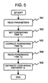
- Fig. 5 is a flowchart of the look-ahead distance estimating unit 104 when a look-ahead distance Ls is estimated according to the host vehicle's speed and a foreseeing time Tp of the driver.
- the look-ahead distance estimating unit 104 reads parameters, such as the driver's steering rotation ⁇ , a host vehicle's speed VSP, and the driver's accelerator operation (step 501), sets at least one of foreseeing times Tp stored in the foreseeing time memory unit 102 (step 502), and by selecting at least one of the parameters read in step 501, corrects the foreseeing time Tp selected in step 502 according to a selected parameter and a road shape recognized by the road shape recognition unit 101 (step 503) .
- parameters such as the driver's steering rotation ⁇ , a host vehicle's speed VSP, and the driver's accelerator operation
- the look-ahead distance estimating unit 104 reads the foreseeing time Tp corrected in step 503 (step 504).
- the foreseeing time Tp read in step 504 may be a foreseeing time set in step 502.
- a look-ahead distance Ls is estimated (step 505), with which the process is finished.
- Fig. 6 is a chart showing an example of a method for selecting a foreseeing time Tp [sec] stored in the foreseeing time memory unit 102.
- RAM random access memory
- Foreseeing times are previously stored in a range of 1.0 to 2.0 [sec]. Meanwhile, regarding foreseeing times Tp to be stored, foreseeing times may be values outside of the range of 1.0 to 2.0 [sec].
- a method for storing foreseeing times Tp at regular intervals in a predetermined range stored, for example, at intervals of 0.1 [sec] in a range of 1.0 to 2.0 [sec]
- foreseeing times Tp may be calculated based on a road shape and a running condition of the host vehicle recognized by the road shape recognition unit 101 to update the foreseeing times Tp in the foreseeing time memory unit 102.
- a foreseeing time is selected either manually by the driver, or automatically according to the road shape and the running condition of the host vehicle running through a curve.
- methods for selecting foreseeing time Tp by the driver there is a method of selecting at least one of foreseeing times Tp which are stored at a rate of one each for a predetermined range as shown in Fig. 6 , and another method for setting foreseeing times Tp by previously setting driving patterns according to the road shape, setting a foreseeing time Tp for each driving pattern, and selecting at least one driving pattern according to the shape of the road that the host vehicle is running on and also according to the running condition.
- a foreseeing time selection image is shown on the display screen on the on-board terminal device, and the driver selects at least one foreseeing time Tp.
- a button or a dial configured to select a foreseeing time Tp may be provided on the instrument panel, and the driver may select a foreseeing time Tp [sec].
- Fig. 6 shows a case a foreseeing time Tp is selected automatically according to a road shape recognized by the road shape recognition unit 101 and a running condition of the host vehicle detected by the parameter detecting unit 105, and illustrates an example of method of selecting a foreseeing time according to a curve length L[m] and the host vehicle's speed VSP[km/h] in this table, for example.
- a foreseeing time Tp[sec] is set according to a curve length L[m] (0 ⁇ Li ⁇ Lj ⁇ Lk ⁇ Lm) of the road the host vehicle is running on and the host vehicle speed VSP[km/h] (0 ⁇ Va ⁇ Vc ⁇ Ve ⁇ Vg) and when the curve length L[m] of the road the host vehicle is running on and the host vehicle speed VSP[km/h] are recognized, a relevant foreseeing time Tp is selected automatically from the table. Or, a foreseeing time Tp may be calculated according to the curve length L[m] of the road the host vehicle is running on and the host vehicle speed VSP[km/h], and a calculated foreseeing time Tp may be selected. Besides the curve length and the host vehicle's speed, other parameters, such as a yaw rate, a rate of lateral acceleration and either acceleration or deceleration may be used.
- a foreseeing time Tp can be selected according to a road shape and host vehicle's speed recognized by the road shape recognition unit 101.
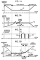
- Fig. 7 is a diagram showing a case where before entering a curve, the host vehicle starts to decelerate and stops decelerating a the entrance of a curve, and then accelerates according to the road shape, which is recognized by the road shape recognition unit 101 while passing through the curve, the driver's steering rotation detected by the parameter detecting unit 105, and the look-ahead distance estimated by the look-ahead distance estimating unit 104 (when the host vehicle drives through a curve and into a straight way).
- Fig. 7A shows the curvature radius R[m] (solid line 702) of the road shape that changes with the position of the running vehicle.
- Fig. 7B shows changes (solid line 704) in the driver's steering rotation (steering angle ⁇ ) according to the road shape while the vehicle is running.
- Fig. 7C shows how acceleration is notified to the driver (706, 707, 708) when the vehicle accelerates according to the driver's steering rotation (steering angle ⁇ ) and a look-ahead distance Ls estimated by the look-ahead distance estimating unit 104.
- Fig. 7D shows changes in the vehicle speed when the vehicle comes out of a straight path and enters a curve, comes out of the curve, and goes on to a straight road again.
- the dashed line 710 shows changes in vehicle speed during deceleration before entering the curve
- the solid line 711 indicates changes in vehicle speed when the vehicle runs through the curve at a constant speed
- the solid line 712 shows changes in speed when the vehicle performs the first acceleration according to the road shape and the steering angle ⁇
- the solid line 713 shows changes in speed when the vehicle performs the second acceleration according to the road shape and the look-ahead distance
- the dotted line illustrates changes in speed after coming out of the curve.
- the speed control unit 111 calculates a target speed according to a curvature radius R(solid line 702) of the road ahead of the host vehicle, recognized by the road shape recognition unit 101, and the vehicle decelerates in such a manner that the deceleration ends at the predetermined curve entrance A (dashed line 710). After the end of deceleration, after the vehicle enters the predetermined curve AB, as illustrated by the solid line 704, the vehicle runs at a constant speed of Vmin until the driver's steering rotation (steering angle ⁇ ) converges in a predetermined range ( ⁇ c ⁇ ⁇ ) (solid line 711).
- the first acceleration determining unit 108 issues a permission to accelerate.
- the speed control unit 111 calculates a target speed according to the road shape recognized by the road shape recognition unit 101 and also according to the first acceleration, the acceleration notification unit 110 notifies the driver that the first acceleration will start (acceleration notification 706), with which the vehicle starts the first acceleration (solid line 712).
- the second acceleration determining unit 109 determines whether or not to perform the second acceleration according to the predetermined curve exit B, recognized by the Ls estimated by the look-ahead distance estimating unit 104. After a lapse of a predetermined time T2 following the arrival of the host vehicle at a point (look-ahead point Q), which is by the look-ahead distance Ls backward from the predetermined curve exit B ahead of the vehicle, the second acceleration determining unit 109 permits the host vehicle to perform the second acceleration.
- the speed control unit calculates a target speed according to the road shape recognized by the road shape recognition unit 101 and also according to the second acceleration, the acceleration notification unit 110 notifies the driver that the second acceleration will start (acceleration notification 707), with which the vehicle starts the second acceleration (solid line 713).
- the acceleration notification unit 110 After the host vehicle has started the second acceleration, when the vehicle is passing the predetermined curve exit B, the acceleration notification unit 110 notifies the driver that the vehicle is getting out of the predetermined curve (acceleration notification 708), and even after the vehicle has come out of the predetermined curve AB, the vehicle continues the second acceleration until the target speed calculated by the speed control unit 111 (solid line 714) is reached. After the first acceleration and the second acceleration have started, if the driver accelerates the host vehicle by depressing the accelerator pedal, this acceleration by the driver's accelerator operation takes priority.
- the first acceleration is performed according to the driver's steering rotation
- a value detected by a yaw rate sensor may be used for the yaw rate ⁇ of the vehicle.
- VSP I ⁇ ⁇ m ⁇ G L m ⁇ VSP 2 / R
- K f and K r are the front wheel cornering power and the rear wheel cornering power
- m is a vehicle weight
- VSP is a vehicle speed.
- the recognition of the road shape by the road shape recognition unit 101 is performed on the on-board terminal device.
- the on-board terminal device a car navigation system or a camera is used.
- the predetermined curve exit B is recognized early from map information loaded in the car navigation system, but if there is an error in the distance from the host vehicle position up to the predetermined curve exit B, by recognition of the predetermined curve exit B through a camera, the error in the distance between the host vehicle position and the predetermined curve exit B is corrected. This enables the vehicle to accelerate without sacrificing the driving comfort when the vehicle is getting out of the predetermined curve.
- the vehicle when a vehicle drives through a curve or gets out of the curve, by controlling the acceleration of the vehicle according to a road shape recognized by the road shape recognition unit 101, the driver's steering rotation detected by the parameter detecting unit 105, and a look-ahead distance estimated by the look-ahead distance estimating unit 104, the vehicle can be accelerated with improved driving comfort for the driver.
- Fig. 8 is a schematic diagram illustrating an example of a case where the host vehicle is prohibited from accelerating in the acceleration determining unit 107 which determines whether or not to accelerate the vehicle according to a road shape recognized by the road shape determining unit 101, the driver's steering rotation detected by the parameter detecting unit 105, and a look-ahead distance estimated by the look-ahead distance estimating unit 104.
- a vehicle 804 is running on a road 801 consisting of straight sections 802a, 802b, and a curve 803.
- a distance 809 from a position P of the host vehicle up to the exit B of the curve is designated as L, a curve length 808 of a curve 803 as Lc, and a look-ahead distance 805 of the vehicle 804 as Ls.
- the road shape recognition unit 101 recognizes a curve 803 ahead of the host vehicle and as the deceleration ends at the entrance of the curve 803, the vehicle enters the curve 803.
- the vehicle speed is controlled based on a acceleration determination performed according to the driver's steering rotation, and a look-ahead distance 805 calculated from a foreseeing time and the host vehicle's speed. Under this situation, the vehicle 804 comes out of the curve 804 and goes on a straight road 802b.
- the case where the vehicle 804 is not accelerated may be as follows: when the driver has operated the accelerator pedal and the brake pedal, when there is a preceding vehicle ahead of the vehicle 803, when speed control by inter-vehicular distance control, such as ACC, takes priority, when the curve length 808 of the curve 803 is shorter than the look-ahead distance 805, when the on-board terminal device recognizes a sign of "Under Construction", for example in the curve 803 ahead of the vehicle 804, when the visibility ahead of the vehicle 804 is poor due to buildings in the vicinity of the curve 803, or when the forward visibility from the vehicle 804 is poor or the surface condition of the road 801 is poor due to a bad weather (rain, fog, snow, for example).
- the acceleration notification unit 110 may notify the driver that the vehicle 804 is not accelerated on the display screen of the on-board terminal device, or by a sound or an alarm.
- the host vehicle is prohibited from accelerating, thus improving the safety of the host vehicle and the driving comfort to the driver along a curve and on a road in the vicinity of the curve.
- Fig. 9 is a flowchart for setting a target speed in the speed control unit 111 when the host vehicle is running along a curve or coming out of a curve.
- the speed control unit 111 reads a road shape and a host vehicle position information recognized by the road shape recognition unit 101 (step 901), reads parameters, such as the driver's steering angle ⁇ , a vehicle speed VSP, ACC target speed Vacc (step 902), and reads an acceleration determination result by the acceleration determining unit 107 and a predetermined acceleration rate based on ACC (step 903).
- a comparison is made between an ACC target speed Vacc read in step 902 and a target speed Vn of the host vehicle calculated in step 905 by using Eq. (8), by which a target speed is selected for the host vehicle (step 906).
- step 906 If the decision condition is established in step 906, since it is determined that the target speed Vn calculated in step 905 is lower than the ACC target speed Vacc, the target speed Vn calculated in step 905 is set as the target speed for the host vehicle (step 907), with which the process is finished.
- step 906 If the decision condition is not established in step 906, since it is determined that the target speed Vn calculated in step 905 is higher than the ACC target speed Vacc, the ACC target speed Vacc read in step 902 is set as the target speed for the host vehicle (step 908), with which the process is finished.
- the current vehicle speed VSP of the host vehicle is set as the target speed for the host vehicle (step 909), with which the process is finished (acceleration is prohibited, running at constant speed).
- Fig. 10 is a diagram showing a relation between the look-ahead distance Ls and the host vehicle's speed.
- the vertical axis indicates the look-ahead distance Ls and the horizontal axis indicates the vehicle speed VSP, and the gradients of the respective straight lines indicate foreseeing times Tp.
- a look-ahead distance Ls which is used when the second acceleration determining unit 109 determines whether to accelerate the host vehicle at the second acceleration, is stored in the foreseeing time memory unit 102.
- the look-ahead distance Ls can be determined according to a foreseeing time Tp corrected by the foreseeing time correcting unit 103 and a vehicle speed VSP. For example, when a foreseeing time is 1.8[sec] (gradient of a straight line), if the vehicle speed VSP is 20[km/h], the look-ahead distance is about 10m, or if the vehicle speed VSP is 40[km/h], the look-ahead distance is about 20m, or if the vehicle speed is 60[km/h], the look-ahead distance is about 30m. So, there is a proportional relation between the look-ahead distance Ls and the vehicle speed VSP as illustrated in Fig. 10 .
- both a look-ahead distance Ls according to the host vehicle's speed VSP and a start point of the second acceleration associated with the look-ahead distance Ls can be determined uniquely.
- the foreseeing time TP may be estimated according to the road shape recognized by the road shape recognition unit 101 and the vehicle speed VSP. For example, when the host vehicle is running at a speed of 60[km/h], if the exit of the curve located at a point 30 m ahead of the host vehicle or a change point of the radius of curvature is recognized by the driver or by the car navigation system or a camera, since the look-ahead distance Ls is 30 m, a foreseeing time Tp can be determined uniquely as 1.8[sec].
- the look-ahead distance Ls may be estimated according to a result of recognition of a change point of the radius of curvature by the car navigation system or the camera in addition to by the look-ahead distance by the driver's foreseeing time.
- the upper-limit number of foreseeing times to be stored in the foreseeing time memory unit 102 can be determined from a road shape and the host vehicle's speed VSP recognized by the road shape recognition unit 101. For example, when the host vehicle is running at a speed of 40[km/h] along a short curve which is 20m in curve length, the foreseeing time Tp is in a range of 0[sec] to 1.8[sec].
- the upper limit of foreseeing time that can be selected from the graph is 1.7[sec]; therefore, the safety in accelerating the vehicle according to a foreseeing time can be ensured.
- a start point of the second acceleration according to the look-ahead distance used for the acceleration determining unit 107 to determine whether or not to perform the second acceleration can be determined according to a foreseeing time Tp and the host vehicle's speed VSP.
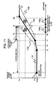
- Fig. 11 is a diagram of a case where the vehicle speed is controlled as illustrated.
- the first road shape recognition unit 112 that recognizes a road shape with reference to map information
- the distance from the host vehicle's position to the predetermined curve exit is corrected by using a road shape recognized by the second road shape recognition unit 113 that recognizes a road shape based on information other than map, and a look-ahead distance estimated by the look-ahead distance estimating unit 104, and the vehicle speed is controlled based on the curve exit point after the correction.
- a curve line from a solid line 1101 to a solid line 1102 shows the changes in the vehicle speed VSP. More specifically, the vehicle finishes deceleration at a specified curve entrance, runs at constant speed of Vmin, and starts the first acceleration at point G according to a steering rotation detected by the parameter detecting unit 105. After the first acceleration is started, the vehicle starts the second acceleration at point H according to a road shape recognized by the road shape recognition unit 101 and a look-ahead distance 1106 estimated by the look-ahead distance estimating unit 104, the vehicle speed VSP reaches a target speed Vn at point C, after which the vehicle speed VSP stays at constant speed Vn.
- a curve line from the solid line 1101 to a dashed line 1104 shows the changes of the host vehicle's speed. After the vehicle finishes decelerating at a predetermined curve entrance A, the vehicle runs at a constant speed of Vmin, and at point G, and starts the first acceleration according to the deriver's steering rotation detected by the parameter detecting unit 105.
- the predetermined curve exit recognized by the road shape recognizing unit 112 is taken as B1 and therefore the second acceleration is started at point H1 according to the look-ahead distance estimated by the look-ahead distance estimating unit 104, and therefore the vehicle speed will reach the target speed Vn at point C1.
- a curve from the solid line 1101 to the dashed line 1105 shows the changes in the vehicle speed CSP.
- the vehicle runs at constant speed of Vmin, and starts the first acceleration at point G according to the driver's steering rotation detected by the parameter detecting unit 105.
- the predetermined curve exit recognized by the first road shape recognizing unit 112 is taken as B2, and therefore the second acceleration is started at point H2 according to the look-ahead distance estimated by the look-ahead distance estimating unit 104, and therefore the vehicle speed will reach the target speed Vn at point C2.
- the predetermined curve exit based on the map information will be B1 or B2, and therefore the host vehicle's speed VSP is controlled as depicted by a line 1104 or 1105.
- the second road shape recognizing unit 113 recognizes a point where the radius of curvature ahead of the vehicle changes by a camera mounted on the vehicle (hereafter referred to as curvature change point), and estimates the predetermined curve exit B by utilizing the curvature change point recognized by the camera.
- the foreseeing time correcting unit 103 corrects a foreseeing time according to the distance between the host vehicle position and the predetermined exit B, and the look-ahead distance estimating unit 104 estimates a look-ahead distance 1106 by using a corrected foreseeing time.
- the predetermined curve exit in map information can be set at B, and the acceleration of the vehicle can be controlled (as shown by the solid line 1102) according to the predetermined curve exit B after the correction described above.
- the information other than map here refers to road information (white and yellow lines, guardrails, road sidewalls, other vehicles, signs, etc.) detected by using a radar (laser, millimeter waves, infrared rays, microwaves, etc.) as well as image information through the camera mounted on the vehicle. If a predetermined curve exit B ahead of the vehicle can be recognized directly by the camera, a foreseeing time may be corrected according to the directly-recognized predetermined curve exit B.
- a radar laser, millimeter waves, infrared rays, microwaves, etc.
- the picture-taking direction of the camera mounted on the vehicle may be in any direction other than in the front direction, such as in the lateral, backward or diagonal direction, namely, in all directions of the vehicle.
- the camera may be a single-lens camera that takes pictures with one camera, or a stereo camera that takes pictures with two cameras.
- a camera may be mounted in each of the left, right, front, and rear directions of the vehicle.
Landscapes
- Engineering & Computer Science (AREA)
- Transportation (AREA)
- Mechanical Engineering (AREA)
- Chemical & Material Sciences (AREA)
- Combustion & Propulsion (AREA)
- Automation & Control Theory (AREA)
- Traffic Control Systems (AREA)
- Control Of Driving Devices And Active Controlling Of Vehicle (AREA)
- Controls For Constant Speed Travelling (AREA)
Applications Claiming Priority (1)
| Application Number | Priority Date | Filing Date | Title |
|---|---|---|---|
| JP2007250389A JP4457136B2 (ja) | 2007-09-27 | 2007-09-27 | 走行制御システム |
Publications (2)
| Publication Number | Publication Date |
|---|---|
| EP2042365A1 true EP2042365A1 (de) | 2009-04-01 |
| EP2042365B1 EP2042365B1 (de) | 2011-07-27 |
Family
ID=40091822
Family Applications (1)
| Application Number | Title | Priority Date | Filing Date |
|---|---|---|---|
| EP08014551A Active EP2042365B1 (de) | 2007-09-27 | 2008-08-14 | Fahrzeuggeschwindigkeitssteuersystem |
Country Status (3)
| Country | Link |
|---|---|
| US (1) | US8170769B2 (de) |
| EP (1) | EP2042365B1 (de) |
| JP (1) | JP4457136B2 (de) |
Cited By (3)
| Publication number | Priority date | Publication date | Assignee | Title |
|---|---|---|---|---|
| DE202015002817U1 (de) * | 2015-04-17 | 2016-07-19 | GM GLOBAL TECHNOLOGY OPERATION LLC (n. d. Ges. d. Staates Delaware) | Abstandsregelungssystem, Kraftfahrzeug sowie Computerprogrammprodukt |
| WO2016146509A1 (de) * | 2015-03-16 | 2016-09-22 | Robert Bosch Gmbh | Verfahren und vorrichtung zur kurvenradiusabhängigen antriebsmomentenregelung für ein kraftfahrzeug während einer kurvenfahrt |
| CN110576849A (zh) * | 2018-06-08 | 2019-12-17 | 株式会社斯巴鲁 | 车辆的行驶控制装置 |
Families Citing this family (32)
| Publication number | Priority date | Publication date | Assignee | Title |
|---|---|---|---|---|
| US9493171B2 (en) * | 2008-10-30 | 2016-11-15 | Ford Global Technologies, Llc | Vehicle and method of advising a driver therein |
| CN102470867B (zh) * | 2009-07-02 | 2015-04-08 | 沃尔沃拉斯特瓦格纳公司 | 用于控制车辆巡航控制的方法和系统 |
| JP5363906B2 (ja) * | 2009-08-05 | 2013-12-11 | 株式会社アドヴィックス | 車両の速度制御装置 |
| US8886365B2 (en) * | 2009-10-30 | 2014-11-11 | Ford Global Technologies, Llc | Vehicle and method for advising driver of same |
| US8258934B2 (en) * | 2009-10-30 | 2012-09-04 | Ford Global Technologies, Llc | Vehicle and method of advising a driver therein |
| US8738228B2 (en) | 2009-10-30 | 2014-05-27 | Ford Global Technologies, Llc | Vehicle and method of tuning performance of same |
| GB2477341A (en) * | 2010-02-01 | 2011-08-03 | Gm Global Tech Operations Inc | A method of estimating a cornering limit of a vehicle |
| WO2011145165A1 (ja) * | 2010-05-17 | 2011-11-24 | トヨタ自動車株式会社 | 運転支援装置 |
| US9283968B2 (en) | 2010-06-08 | 2016-03-15 | Toyota Jidosha Kabushiki Kaisha | Driving model creating apparatus and driving support apparatus |
| JP5785416B2 (ja) * | 2011-03-29 | 2015-09-30 | 本田技研工業株式会社 | 車両用運転操作支援装置 |
| US8712691B2 (en) * | 2011-12-19 | 2014-04-29 | Ford Global Technologies | Fusion of road geometry model information gathered from disparate sources |
| US9187118B2 (en) * | 2011-12-30 | 2015-11-17 | C & P Technologies, Inc. | Method and apparatus for automobile accident reduction using localized dynamic swarming |
| KR101380888B1 (ko) * | 2012-07-24 | 2014-04-02 | 현대모비스 주식회사 | 차간 거리 산출 장치 및 방법 |
| JP6161942B2 (ja) * | 2013-04-19 | 2017-07-12 | 株式会社デンソーアイティーラボラトリ | カーブ形状モデル化装置、車両情報処理システム、カーブ形状モデル化方法、及びカーブ形状モデル化プログラム |
| GB2516933B (en) * | 2013-08-07 | 2017-06-28 | Jaguar Land Rover Ltd | Vehicle speed control system and method |
| US20150268665A1 (en) * | 2013-11-07 | 2015-09-24 | Google Inc. | Vehicle communication using audible signals |
| SE539254C2 (sv) * | 2014-05-21 | 2017-05-30 | Scania Cv Ab | Förfarande och system för anpassning av ett fordons hastighet vid kurvkörning |
| JP2017030578A (ja) * | 2015-08-02 | 2017-02-09 | 株式会社デンソー | 自動運転制御装置、自動運転制御方法 |
| JP6344695B2 (ja) * | 2015-10-28 | 2018-06-20 | 本田技研工業株式会社 | 車両制御装置、車両制御方法、および車両制御プログラム |
| US10379538B1 (en) * | 2017-03-20 | 2019-08-13 | Zoox, Inc. | Trajectory generation using motion primitives |
| US10449959B2 (en) * | 2017-10-30 | 2019-10-22 | Wipro Limited | System and method for navigating an autonomous vehicle |
| CN111133447B (zh) | 2018-02-18 | 2024-03-19 | 辉达公司 | 适于自主驾驶的对象检测和检测置信度的方法和系统 |
| WO2019168869A1 (en) | 2018-02-27 | 2019-09-06 | Nvidia Corporation | Real-time detection of lanes and boundaries by autonomous vehicles |
| US11537139B2 (en) | 2018-03-15 | 2022-12-27 | Nvidia Corporation | Determining drivable free-space for autonomous vehicles |
| DE112019006484T5 (de) | 2018-12-28 | 2021-10-21 | Nvidia Corporation | Detektion von abständen zu hindernissen in autonomen maschinenanwendungen |
| US11170299B2 (en) | 2018-12-28 | 2021-11-09 | Nvidia Corporation | Distance estimation to objects and free-space boundaries in autonomous machine applications |
| US11182916B2 (en) * | 2018-12-28 | 2021-11-23 | Nvidia Corporation | Distance to obstacle detection in autonomous machine applications |
| US11648945B2 (en) | 2019-03-11 | 2023-05-16 | Nvidia Corporation | Intersection detection and classification in autonomous machine applications |
| JP2019135150A (ja) * | 2019-04-25 | 2019-08-15 | 株式会社デンソー | 自動運転制御装置、自動運転制御方法 |
| WO2021042051A1 (en) | 2019-08-31 | 2021-03-04 | Nvidia Corporation | Map creation and localization for autonomous driving applications |
| US11978266B2 (en) | 2020-10-21 | 2024-05-07 | Nvidia Corporation | Occupant attentiveness and cognitive load monitoring for autonomous and semi-autonomous driving applications |
| JP7415975B2 (ja) * | 2021-02-12 | 2024-01-17 | トヨタ自動車株式会社 | 車両の走行支援システム、及び、車両の走行支援方法 |
Citations (4)
| Publication number | Priority date | Publication date | Assignee | Title |
|---|---|---|---|---|
| EP0798150A2 (de) * | 1996-03-26 | 1997-10-01 | Jaguar Cars Limited | Reisegeschwindigkeits-Steuerungssystem mit Fahrzeug-Folgemodalität |
| JP2004142686A (ja) | 2002-10-28 | 2004-05-20 | Hitachi Ltd | 自動車用走行制御装置および自動車の走行制御システム |
| JP2005309955A (ja) | 2004-04-23 | 2005-11-04 | Nissan Motor Co Ltd | 前方道路対応制御装置 |
| WO2007070160A2 (en) | 2005-12-09 | 2007-06-21 | Gm Global Technology Operations, Inc. | Speed control method for vehicle approaching and traveling on a curve |
Family Cites Families (4)
| Publication number | Priority date | Publication date | Assignee | Title |
|---|---|---|---|---|
| US5673039A (en) * | 1992-04-13 | 1997-09-30 | Pietzsch Ag | Method of monitoring vehicular traffic and of providing information to drivers and system for carring out the method |
| JP4494162B2 (ja) | 2004-10-15 | 2010-06-30 | 富士通テン株式会社 | 運転支援装置 |
| JP2006309966A (ja) | 2005-04-26 | 2006-11-09 | Shoji Komuro | 照明器具 |
| KR100793869B1 (ko) * | 2005-12-17 | 2008-01-15 | 현대자동차주식회사 | 차량의 차간거리 제어 시스템 |
-
2007
- 2007-09-27 JP JP2007250389A patent/JP4457136B2/ja active Active
-
2008
- 2008-08-14 EP EP08014551A patent/EP2042365B1/de active Active
- 2008-08-20 US US12/194,767 patent/US8170769B2/en active Active
Patent Citations (4)
| Publication number | Priority date | Publication date | Assignee | Title |
|---|---|---|---|---|
| EP0798150A2 (de) * | 1996-03-26 | 1997-10-01 | Jaguar Cars Limited | Reisegeschwindigkeits-Steuerungssystem mit Fahrzeug-Folgemodalität |
| JP2004142686A (ja) | 2002-10-28 | 2004-05-20 | Hitachi Ltd | 自動車用走行制御装置および自動車の走行制御システム |
| JP2005309955A (ja) | 2004-04-23 | 2005-11-04 | Nissan Motor Co Ltd | 前方道路対応制御装置 |
| WO2007070160A2 (en) | 2005-12-09 | 2007-06-21 | Gm Global Technology Operations, Inc. | Speed control method for vehicle approaching and traveling on a curve |
Cited By (3)
| Publication number | Priority date | Publication date | Assignee | Title |
|---|---|---|---|---|
| WO2016146509A1 (de) * | 2015-03-16 | 2016-09-22 | Robert Bosch Gmbh | Verfahren und vorrichtung zur kurvenradiusabhängigen antriebsmomentenregelung für ein kraftfahrzeug während einer kurvenfahrt |
| DE202015002817U1 (de) * | 2015-04-17 | 2016-07-19 | GM GLOBAL TECHNOLOGY OPERATION LLC (n. d. Ges. d. Staates Delaware) | Abstandsregelungssystem, Kraftfahrzeug sowie Computerprogrammprodukt |
| CN110576849A (zh) * | 2018-06-08 | 2019-12-17 | 株式会社斯巴鲁 | 车辆的行驶控制装置 |
Also Published As
| Publication number | Publication date |
|---|---|
| JP2009078732A (ja) | 2009-04-16 |
| US20090088941A1 (en) | 2009-04-02 |
| EP2042365B1 (de) | 2011-07-27 |
| US8170769B2 (en) | 2012-05-01 |
| JP4457136B2 (ja) | 2010-04-28 |
Similar Documents
| Publication | Publication Date | Title |
|---|---|---|
| EP2042365B1 (de) | Fahrzeuggeschwindigkeitssteuersystem | |
| US11680820B2 (en) | Map information system | |
| US6873911B2 (en) | Method and system for vehicle operator assistance improvement | |
| JP3167987B2 (ja) | カーブ進入制御装置 | |
| US6738705B2 (en) | Vehicle running control apparatus and map information data recording medium | |
| US7925413B2 (en) | Vehicle control system | |
| US20210188258A1 (en) | Vehicle control device | |
| US11091035B2 (en) | Automatic driving system | |
| US8150591B2 (en) | Vehicle travel speed control method | |
| US20170120909A1 (en) | Vehicle control apparatus, vehicle control method, and vehicle control program | |
| US11830364B2 (en) | Driving assist method and driving assist device | |
| RU2767216C1 (ru) | Способ управления движением транспортного средства и аппаратура управления движением транспортного средства | |
| JP2019084842A (ja) | 車両制御装置 | |
| JP4232806B2 (ja) | 車両制御装置 | |
| EP1085296B1 (de) | Kurvenannäherungssteuervorrichtung | |
| US20190263412A1 (en) | Vehicle control device and vehicle control method | |
| US20220073098A1 (en) | Method and apparatus for predicting lateral acceleration prior to an automated lane change | |
| JP2019138773A (ja) | 表示装置 | |
| US20190367032A1 (en) | Travelling control apparatus | |
| JP5660139B2 (ja) | 車両用情報処理装置及びデータベース | |
| JP2008213581A (ja) | 車両の運転支援方法及び車両の運転支援装置 | |
| US11427252B2 (en) | Automatic driving system | |
| JP7107095B2 (ja) | 自動運転システム | |
| JP2004219316A (ja) | 車両進行路推定装置 | |
| JP2006142904A (ja) | 車両のブレーキ制御装置 |
Legal Events
| Date | Code | Title | Description |
|---|---|---|---|
| PUAI | Public reference made under article 153(3) epc to a published international application that has entered the european phase |
Free format text: ORIGINAL CODE: 0009012 |
|
| 17P | Request for examination filed |
Effective date: 20080814 |
|
| AK | Designated contracting states |
Kind code of ref document: A1 Designated state(s): AT BE BG CH CY CZ DE DK EE ES FI FR GB GR HR HU IE IS IT LI LT LU LV MC MT NL NO PL PT RO SE SI SK TR |
|
| AX | Request for extension of the european patent |
Extension state: AL BA MK RS |
|
| AKX | Designation fees paid |
Designated state(s): DE FR GB IT |
|
| 17Q | First examination report despatched |
Effective date: 20091120 |
|
| GRAP | Despatch of communication of intention to grant a patent |
Free format text: ORIGINAL CODE: EPIDOSNIGR1 |
|
| GRAS | Grant fee paid |
Free format text: ORIGINAL CODE: EPIDOSNIGR3 |
|
| GRAA | (expected) grant |
Free format text: ORIGINAL CODE: 0009210 |
|
| AK | Designated contracting states |
Kind code of ref document: B1 Designated state(s): DE FR GB IT |
|
| REG | Reference to a national code |
Ref country code: GB Ref legal event code: FG4D |
|
| REG | Reference to a national code |
Ref country code: DE Ref legal event code: R096 Ref document number: 602008008470 Country of ref document: DE Effective date: 20110922 |
|
| PLBE | No opposition filed within time limit |
Free format text: ORIGINAL CODE: 0009261 |
|
| STAA | Information on the status of an ep patent application or granted ep patent |
Free format text: STATUS: NO OPPOSITION FILED WITHIN TIME LIMIT |
|
| 26N | No opposition filed |
Effective date: 20120502 |
|
| REG | Reference to a national code |
Ref country code: DE Ref legal event code: R097 Ref document number: 602008008470 Country of ref document: DE Effective date: 20120502 |
|
| PGFP | Annual fee paid to national office [announced via postgrant information from national office to epo] |
Ref country code: IT Payment date: 20120810 Year of fee payment: 5 |
|
| PGFP | Annual fee paid to national office [announced via postgrant information from national office to epo] |
Ref country code: GB Payment date: 20130814 Year of fee payment: 6 |
|
| PG25 | Lapsed in a contracting state [announced via postgrant information from national office to epo] |
Ref country code: IT Free format text: LAPSE BECAUSE OF NON-PAYMENT OF DUE FEES Effective date: 20130814 |
|
| GBPC | Gb: european patent ceased through non-payment of renewal fee |
Effective date: 20140814 |
|
| PG25 | Lapsed in a contracting state [announced via postgrant information from national office to epo] |
Ref country code: GB Free format text: LAPSE BECAUSE OF NON-PAYMENT OF DUE FEES Effective date: 20140814 |
|
| REG | Reference to a national code |
Ref country code: FR Ref legal event code: PLFP Year of fee payment: 9 |
|
| REG | Reference to a national code |
Ref country code: FR Ref legal event code: PLFP Year of fee payment: 10 |
|
| REG | Reference to a national code |
Ref country code: FR Ref legal event code: PLFP Year of fee payment: 11 |
|
| REG | Reference to a national code |
Ref country code: DE Ref legal event code: R081 Ref document number: 602008008470 Country of ref document: DE Owner name: HITACHI ASTEMO, LTD., HITACHINAKA-SHI, JP Free format text: FORMER OWNER: HITACHI AUTOMOTIVE SYSTEMS, LTD., HITACHINAKA-SHI, IBARAKI, JP Ref country code: DE Ref legal event code: R081 Ref document number: 602008008470 Country of ref document: DE Owner name: HITACHI ASTEMO, LTD., HITACHINAKA-SHI, JP Free format text: FORMER OWNER: HITACHI, LTD., TOKYO, JP |
|
| PGFP | Annual fee paid to national office [announced via postgrant information from national office to epo] |
Ref country code: FR Payment date: 20230703 Year of fee payment: 16 Ref country code: DE Payment date: 20230627 Year of fee payment: 16 |