EP2040933B1 - Dispenser with attachment system - Google Patents
Dispenser with attachment system Download PDFInfo
- Publication number
- EP2040933B1 EP2040933B1 EP07799432.5A EP07799432A EP2040933B1 EP 2040933 B1 EP2040933 B1 EP 2040933B1 EP 07799432 A EP07799432 A EP 07799432A EP 2040933 B1 EP2040933 B1 EP 2040933B1
- Authority
- EP
- European Patent Office
- Prior art keywords
- dispenser
- holding film
- lower member
- attachment mechanism
- film
- Prior art date
- Legal status (The legal status is an assumption and is not a legal conclusion. Google has not performed a legal analysis and makes no representation as to the accuracy of the status listed.)
- Active
Links
- 230000007246 mechanism Effects 0.000 claims description 32
- 239000000853 adhesive Substances 0.000 claims description 25
- 230000001070 adhesive effect Effects 0.000 claims description 25
- 230000004913 activation Effects 0.000 claims description 18
- 229920002943 EPDM rubber Polymers 0.000 claims description 6
- 229920002635 polyurethane Polymers 0.000 claims description 3
- 239000004814 polyurethane Substances 0.000 claims description 3
- 229920000642 polymer Polymers 0.000 claims 1
- 239000002023 wood Substances 0.000 description 6
- 239000011248 coating agent Substances 0.000 description 5
- 238000000576 coating method Methods 0.000 description 5
- 239000000463 material Substances 0.000 description 5
- 238000012360 testing method Methods 0.000 description 5
- 230000033001 locomotion Effects 0.000 description 4
- BRLQWZUYTZBJKN-UHFFFAOYSA-N Epichlorohydrin Chemical compound ClCC1CO1 BRLQWZUYTZBJKN-UHFFFAOYSA-N 0.000 description 3
- 239000004830 Super Glue Substances 0.000 description 3
- FGBJXOREULPLGL-UHFFFAOYSA-N ethyl cyanoacrylate Chemical compound CCOC(=O)C(=C)C#N FGBJXOREULPLGL-UHFFFAOYSA-N 0.000 description 3
- JOYRKODLDBILNP-UHFFFAOYSA-N Ethyl urethane Chemical compound CCOC(N)=O JOYRKODLDBILNP-UHFFFAOYSA-N 0.000 description 2
- KDLHZDBZIXYQEI-UHFFFAOYSA-N Palladium Chemical compound [Pd] KDLHZDBZIXYQEI-UHFFFAOYSA-N 0.000 description 2
- 239000003302 ferromagnetic material Substances 0.000 description 2
- 239000007788 liquid Substances 0.000 description 2
- 239000002184 metal Substances 0.000 description 2
- 229910052751 metal Inorganic materials 0.000 description 2
- 238000000034 method Methods 0.000 description 2
- 229920003031 santoprene Polymers 0.000 description 2
- 230000003746 surface roughness Effects 0.000 description 2
- 238000010998 test method Methods 0.000 description 2
- 239000004820 Pressure-sensitive adhesive Substances 0.000 description 1
- 235000013361 beverage Nutrition 0.000 description 1
- 239000002537 cosmetic Substances 0.000 description 1
- 238000005034 decoration Methods 0.000 description 1
- 230000001419 dependent effect Effects 0.000 description 1
- -1 e.g. Substances 0.000 description 1
- 229920001971 elastomer Polymers 0.000 description 1
- 238000004049 embossing Methods 0.000 description 1
- PCHJSUWPFVWCPO-UHFFFAOYSA-N gold Chemical compound [Au] PCHJSUWPFVWCPO-UHFFFAOYSA-N 0.000 description 1
- 239000010931 gold Substances 0.000 description 1
- 229910052737 gold Inorganic materials 0.000 description 1
- 230000003100 immobilizing effect Effects 0.000 description 1
- 238000009434 installation Methods 0.000 description 1
- 239000011810 insulating material Substances 0.000 description 1
- 239000004922 lacquer Substances 0.000 description 1
- 239000007769 metal material Substances 0.000 description 1
- 150000002739 metals Chemical class 0.000 description 1
- 230000003287 optical effect Effects 0.000 description 1
- 229910052763 palladium Inorganic materials 0.000 description 1
- 239000004033 plastic Substances 0.000 description 1
- 229920003023 plastic Polymers 0.000 description 1
- 239000002985 plastic film Substances 0.000 description 1
- 229920006255 plastic film Polymers 0.000 description 1
- 239000004014 plasticizer Substances 0.000 description 1
- 239000011527 polyurethane coating Substances 0.000 description 1
- 239000002990 reinforced plastic Substances 0.000 description 1
- 238000004439 roughness measurement Methods 0.000 description 1
- 239000005060 rubber Substances 0.000 description 1
- 238000007789 sealing Methods 0.000 description 1
- 238000007655 standard test method Methods 0.000 description 1
- 239000000758 substrate Substances 0.000 description 1
- 238000012876 topography Methods 0.000 description 1
Images


Classifications
-
- B—PERFORMING OPERATIONS; TRANSPORTING
- B42—BOOKBINDING; ALBUMS; FILES; SPECIAL PRINTED MATTER
- B42D—BOOKS; BOOK COVERS; LOOSE LEAVES; PRINTED MATTER CHARACTERISED BY IDENTIFICATION OR SECURITY FEATURES; PRINTED MATTER OF SPECIAL FORMAT OR STYLE NOT OTHERWISE PROVIDED FOR; DEVICES FOR USE THEREWITH AND NOT OTHERWISE PROVIDED FOR; MOVABLE-STRIP WRITING OR READING APPARATUS
- B42D5/00—Sheets united without binding to form pads or blocks
- B42D5/003—Note-pads
- B42D5/005—Supports for note-pads
- B42D5/006—Supports for note-pads combined with auxiliary devices
-
- B—PERFORMING OPERATIONS; TRANSPORTING
- B42—BOOKBINDING; ALBUMS; FILES; SPECIAL PRINTED MATTER
- B42D—BOOKS; BOOK COVERS; LOOSE LEAVES; PRINTED MATTER CHARACTERISED BY IDENTIFICATION OR SECURITY FEATURES; PRINTED MATTER OF SPECIAL FORMAT OR STYLE NOT OTHERWISE PROVIDED FOR; DEVICES FOR USE THEREWITH AND NOT OTHERWISE PROVIDED FOR; MOVABLE-STRIP WRITING OR READING APPARATUS
- B42D5/00—Sheets united without binding to form pads or blocks
- B42D5/003—Note-pads
- B42D5/005—Supports for note-pads
-
- B—PERFORMING OPERATIONS; TRANSPORTING
- B42—BOOKBINDING; ALBUMS; FILES; SPECIAL PRINTED MATTER
- B42D—BOOKS; BOOK COVERS; LOOSE LEAVES; PRINTED MATTER CHARACTERISED BY IDENTIFICATION OR SECURITY FEATURES; PRINTED MATTER OF SPECIAL FORMAT OR STYLE NOT OTHERWISE PROVIDED FOR; DEVICES FOR USE THEREWITH AND NOT OTHERWISE PROVIDED FOR; MOVABLE-STRIP WRITING OR READING APPARATUS
- B42D15/00—Printed matter of special format or style not otherwise provided for
- B42D15/0073—Printed matter of special format or style not otherwise provided for characterised by shape or material of the sheets
- B42D15/0093—Sheet materials
-
- B—PERFORMING OPERATIONS; TRANSPORTING
- B42—BOOKBINDING; ALBUMS; FILES; SPECIAL PRINTED MATTER
- B42F—SHEETS TEMPORARILY ATTACHED TOGETHER; FILING APPLIANCES; FILE CARDS; INDEXING
- B42F7/00—Filing appliances without fastening means
- B42F7/14—Boxes
-
- B—PERFORMING OPERATIONS; TRANSPORTING
- B65—CONVEYING; PACKING; STORING; HANDLING THIN OR FILAMENTARY MATERIAL
- B65D—CONTAINERS FOR STORAGE OR TRANSPORT OF ARTICLES OR MATERIALS, e.g. BAGS, BARRELS, BOTTLES, BOXES, CANS, CARTONS, CRATES, DRUMS, JARS, TANKS, HOPPERS, FORWARDING CONTAINERS; ACCESSORIES, CLOSURES, OR FITTINGS THEREFOR; PACKAGING ELEMENTS; PACKAGES
- B65D83/00—Containers or packages with special means for dispensing contents
- B65D83/08—Containers or packages with special means for dispensing contents for dispensing thin flat articles in succession
- B65D83/0805—Containers or packages with special means for dispensing contents for dispensing thin flat articles in succession through an aperture in a wall
- B65D83/0811—Containers or packages with special means for dispensing contents for dispensing thin flat articles in succession through an aperture in a wall with means for assisting dispensing
- B65D83/0817—Containers or packages with special means for dispensing contents for dispensing thin flat articles in succession through an aperture in a wall with means for assisting dispensing the articles being automatically urged towards the dispensing aperture, e.g. spring-loaded
-
- F—MECHANICAL ENGINEERING; LIGHTING; HEATING; WEAPONS; BLASTING
- F16—ENGINEERING ELEMENTS AND UNITS; GENERAL MEASURES FOR PRODUCING AND MAINTAINING EFFECTIVE FUNCTIONING OF MACHINES OR INSTALLATIONS; THERMAL INSULATION IN GENERAL
- F16B—DEVICES FOR FASTENING OR SECURING CONSTRUCTIONAL ELEMENTS OR MACHINE PARTS TOGETHER, e.g. NAILS, BOLTS, CIRCLIPS, CLAMPS, CLIPS OR WEDGES; JOINTS OR JOINTING
- F16B47/00—Suction cups for attaching purposes; Equivalent means using adhesives
-
- A—HUMAN NECESSITIES
- A47—FURNITURE; DOMESTIC ARTICLES OR APPLIANCES; COFFEE MILLS; SPICE MILLS; SUCTION CLEANERS IN GENERAL
- A47K—SANITARY EQUIPMENT NOT OTHERWISE PROVIDED FOR; TOILET ACCESSORIES
- A47K2201/00—Details of connections of bathroom accessories, e.g. fixing soap or towel holder to a wall
-
- Y—GENERAL TAGGING OF NEW TECHNOLOGICAL DEVELOPMENTS; GENERAL TAGGING OF CROSS-SECTIONAL TECHNOLOGIES SPANNING OVER SEVERAL SECTIONS OF THE IPC; TECHNICAL SUBJECTS COVERED BY FORMER USPC CROSS-REFERENCE ART COLLECTIONS [XRACs] AND DIGESTS
- Y10—TECHNICAL SUBJECTS COVERED BY FORMER USPC
- Y10T—TECHNICAL SUBJECTS COVERED BY FORMER US CLASSIFICATION
- Y10T428/00—Stock material or miscellaneous articles
- Y10T428/14—Layer or component removable to expose adhesive
- Y10T428/1481—Dissimilar adhesives
-
- Y—GENERAL TAGGING OF NEW TECHNOLOGICAL DEVELOPMENTS; GENERAL TAGGING OF CROSS-SECTIONAL TECHNOLOGIES SPANNING OVER SEVERAL SECTIONS OF THE IPC; TECHNICAL SUBJECTS COVERED BY FORMER USPC CROSS-REFERENCE ART COLLECTIONS [XRACs] AND DIGESTS
- Y10—TECHNICAL SUBJECTS COVERED BY FORMER USPC
- Y10T—TECHNICAL SUBJECTS COVERED BY FORMER US CLASSIFICATION
- Y10T428/00—Stock material or miscellaneous articles
- Y10T428/24—Structurally defined web or sheet [e.g., overall dimension, etc.]
- Y10T428/24008—Structurally defined web or sheet [e.g., overall dimension, etc.] including fastener for attaching to external surface
- Y10T428/24017—Hook or barb
-
- Y—GENERAL TAGGING OF NEW TECHNOLOGICAL DEVELOPMENTS; GENERAL TAGGING OF CROSS-SECTIONAL TECHNOLOGIES SPANNING OVER SEVERAL SECTIONS OF THE IPC; TECHNICAL SUBJECTS COVERED BY FORMER USPC CROSS-REFERENCE ART COLLECTIONS [XRACs] AND DIGESTS
- Y10—TECHNICAL SUBJECTS COVERED BY FORMER USPC
- Y10T—TECHNICAL SUBJECTS COVERED BY FORMER US CLASSIFICATION
- Y10T428/00—Stock material or miscellaneous articles
- Y10T428/24—Structurally defined web or sheet [e.g., overall dimension, etc.]
- Y10T428/24355—Continuous and nonuniform or irregular surface on layer or component [e.g., roofing, etc.]
Definitions
- the present invention pertains to dispensers used in conjunction with an attachment system.
- the attachment system when attached to a dispenser, allows for one-handed removal of a sheet disposed in the dispenser.
- suction cups can be used on a surface, such as windows and doors, for displaying decorations or to hold an item in a desired place.
- Typical suction cups have a circular rim and a concave surface that is intended to be in contact with a display surface once the suction cup is mounted. In many cases, the suction cup holds an item in place, whether on a vertical or horizontal surface.
- a user typically breaks the suction between the suction cup and the surface, by, e.g., wedging a device between the two.
- Other devices used for attaching an item to a surface include adhesive and ferro-magnetic materials. However, these materials have limitations regarding relative movement of the device and the types of surfaces that can be used. For example, use of ferro-magnetic materials as the attachment device would necessarily limit a display surface to a metal-based material.
- US Patent No. 5,014,946 discloses a holding, retaining, and adhering means comprising a holding member characterized by a flexible plate connected to a bottom surface of a comparatively rigid holding member at a fastening point located at an inner surface of the flexible plate.
- the flexible plate is adapted to an unevenness of a surface upon which it is placed such that when a tilting or tipping force is applied, a drawing-off force is likewise applied to the rigid holding member.
- US 5,180,132 describes a suction device which has a flexible cup member whose lower surface defines a flat central zone surrounded by an annular zone sloping inwardly and upwardly at an angle of 2° to 10° with the central zone.
- An article holder such as a beverage can receptacle, has a rigid circular base centrally secured to the upper surface of the cup member, opposite the central zone thereof.
- US 2002/0079417 describes a device for selectively immobilizing a container, such as a container containing a cosmetic product, on a surface which may include a sleeve having a free edge defining an opening for mounting the device on the container.
- US 4,907,825 describes a sheet including a layer of flexible polymeric material having a coating of repositionable pressure sensitive adhesive on a second end portion that is generally transparent when adhered to a substrate, while being free of adhesive along a visually distinctive first end portion.
- a pad of the sheets in a stack with adjacent ends of the sheets aligned and with the first and second ends of successive sheets adjacent can be disposed in a chamber partially defined by a top wall having a slot through which the first end portion of the uppermost sheet projects.
- US 5,358,141 describes a dispenser for flexible sheets from a stack of adhesive coated sheets disposed one on top of another.
- the dispenser comprises a first housing portion including a bottom wall, end walls, side walls and a first top wall portion; and a second housing portion comprising a second top wall portion mounted on the fist housing portion for movement between a normal position where the top wall portions define an outlet opening for the sheets between adjacent ends, and an open position with the second top wall portion spaced from the first wall portion to afford inserting a stack of sheets into the cavity.
- dispensers with other attachment systems that are easy to use and capable of being used on a variety of surfaces spanning from wood, to metals, to plastic surfaces.
- the present invention is defined by the features of independent claim 1. Further preferred embodiments of the invention are defined in the dependent claims.
- the dispensers of the present invention exhibit temporary attachment between a work surface, such as a table top.
- an attachment system comprising (a) a polymeric holding film having a first major surface and a flexural modulus of less than about 50 MPa, as measured according to ASTM D790 standard, and a roughness parameter, R a , of less than about 1 micrometer, as calculated according to ASME B46.1 standard, and (b) an attachment mechanism disposed on the first major surface of the holding film.
- the holding film has a first surface area.
- the attachment mechanism has a second surface area. The ratio of the first to second surface area is from about 10:1 to 3:1.
- the holding film is circular in geometry while the attachment mechanism is either square or circular.
- the present invention pertains to a dispenser as defined in claim 1.
- the attachment system of the dispenser allows to create a vacuum and cling to a wide variety of surfaces, from smooth surfaces such as metal based tables, to rougher surfaces such as wood based table tops.
- a dispenser is used in combination with the attachment system such that the holding film is in direct contact with a work surface, the dispenser is able to slide across the work surface. It is believed that the sliding motion may increase the vacuum.
- the vacuum keeps the dispenser in place when a sheet material is removed therefrom.
- One aspect of the present invention involves a dispenser with an attachment system that includes a polymeric holding film and an attachment mechanism. Unlike the traditional suction cup that holds an item in one place until the suction is broken, the attachment system allows the dispenser to remain stationary during dispensing while also allowing it to slide when pushed across a work surface.
- the holding film has a flexural modulus less than 50 mega pascals (MPa), preferably less than 25 MPa, more preferably less than 10 MPa, and most preferably in the range of 5 to 7 MPa, as tested according ASTM D790 Standard Test Methods for Flexural Properties of Unreinforced and Reinforced Plastics and Electrical Insulating Materials.
- MPa mega pascals
- this test method involves a three-point bend test where the test conditions includes a span of 16 mm and a cross-head speed of 5 mm per minute and where the sample had a width of 25.4 mm and a length of 50 mm.
- the holding film has an average roughness parameter (R a ) of less than 1 micrometer, calculated over the entire sample testing area.
- the roughness measurement is calculated according to ASME B46.1 standard.
- a sample of the holding film was first coated with a gold/palladium film (using a current of 40 mA and 10 second) and the film's surface topography or roughness was measured using a Wyko NT3300 optical interferometer operated in VSI mode with a 10x objection and a 2% modulation threshold.
- a useful polymeric holding film has a Shore A durometer of less than 70.
- the film has a thickness of 0.01 to 0.1 inch (0.25 to 2.5mm).
- the preferred ranges of flexural modulus, roughness, Shore A durometer, and thickness are characteristics of the polymeric film that tends to exhibit better drape of the film once attached to the dispenser.
- the holding film has minimal amount of plasticizers, which could, over time, alter the film's effectiveness to create and maintain a vacuum.
- the film should be sufficiently chemically inert over time so as not to stain the work surface upon which it is placed or to affect the attachment mechanism used to attach the film to the article.
- Suitable polymeric films include polyurethane and rubbers made with ethylene propylene diene monomers (EPDM).
- EPDM ethylene propylene diene monomers
- Commercially available EPDM films include those available from McMaster-Carr, Atlanta, Georgia under product numbers 8610 K81 and 8143 K11.
- the attachment mechanism can be mechanical based or adhesive based. Selection of the appropriate attachment mechanism depends on the user's preference as well as the article used.
- the attachment mechanism is located centrally on the holding film.
- a suitable mechanical based attachment systems include recloseable fasteners, such as those described in US Patent No. 6,972,141 (Bries et al. ).
- a suitable adhesive based attachment mechanism is a stretch release adhesive strip with a rounded non-adhesive end tab available from 3M Company under the CommandTM brand.
- the adhesive strip includes a double-sided adhesive portion where one side adheres to the exterior surface of the lower member while the other side adheres to the first surface of the holding film. By pulling on the non-adhesive end tab, the consumer disengages the stretch release adhesive from both surfaces. In this way, the holding film can be reused on a new dispenser, if desired.
- Yet another suitable adhesive based attachment mechanism is double sided tape, such as those commercially available from 3M Company under product number 4462W and 4466W.
- Yet another suitable adhesive based attachment mechanism involves the use of a cyanoacrylate adhesive, which is typically supplied in liquid form.
- the liquid adhesive can be dispensed on the holding film and applied to the exterior surface of the lower member where it will cure thereby bonding the two layers together.
- 3MTM Scotch-WeldTM Instant Adhesive, product designation CA40H is a suitable cyanoacrylate adhesive that can be used in the present invention. This particular adhesive cures at room temperature (about 23°C).
- the design and size of the attachment mechanism relative to the holding film can affect the vacuum between the film and the work surface when a substantially normal force is imposed on the article to which the attachment system is attached.
- holding films having circular geometries and attachment mechanism having either circular or square geometry are suitable.
- Other geometries for holding films and attachment mechanisms can also be used in the present invention.
- the ratio of the surface area of the holding film to the surface area of the attachment mechanism is from 10:1 to 3:1.
- the attachment mechanism is typically positioned nearly at the center of the holding film. After the holding film has been attached to the dispenser, a side view of the dispenser would show that the holding film crowns slightly toward the attachment site.
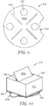
- FIG. 1 shows an exploded view of an exemplary dispenser of the present invention, which is particularly useful for dispensing a large number (greater than about 50 to 100) of sheets arranged in fan-fold (often referred to as "z" fold) stack 38.
- a sheet is disclosed in US Patent No. 4,907,825 (Miles et. al) .
- the dispenser includes a cover (also referred to as an "upper member") 20 having substantially a circular rim.
- the upper member has two side portions 22 extending from opposing halves of the circular rim and protrusion 24 disposed between the two side portions.
- the protrusion is formed by two sidewalls 25 that extend from the side portions.
- the protrusion also has two sloping walls 29 that end at opposing regions of the rim. At a top of the protrusion, there is an opening (commonly referred to as a "slot") 26 that is appropriately sized to allow for removal of a sheet in the stack.
- the upper member further includes a depression 27 and a cut-out section 28 on one side portion.
- the dispenser of Figure 1 further includes base (also referred to as a "lower member") 30 having a geometry that is substantially similar to that of the rim of cover 20.
- a housing is formed when the upper member is assembled to the lower member.
- the lower member also has cutout 31 that is substantially similar to and coinciding with cutout 28 of the upper member. When the upper and lower members are assembled, the two cutouts are generally aligned.
- the lower member has opposing interior surface 30a and exterior surface (not shown).
- Optional biasing mechanism in this case a spring 32, rests on the interior surface of the lower member.
- Optional plate 34 provides a platform for stack of sheets 38, which rests on a first surface 34a of the plate. The second surface of the plate contacts the spring.
- the plate further includes optional ribs 36 at its opposing ends 35.
- the ribs provide a stop for the stack as it shuttles from one end to the other when an individual sheet is removed.
- US Patent No. 4,907,825 discloses the shuttling concept in detail.
- the upper member is made of a transparent polymeric material and the lower member is made from cardstock that has a coating of heat activated adhesive on its rim, and the two parts are assembled together using heat sealing. Clear upper members can be used as they allow the users to see inside the housing.
- a holding film 50 is attached to the exterior surface of the lower member via an attachment mechanism 40.
- the combination of the holding film and the attachment mechanism make up the attachment system.
- the holding film is substantially circular and is generally of the same dimensions as the lower member, except that the holding film does not include a cut out section.
- the dispenser has a holding film diameter of 3 inches (7.62 cm) and the attachment mechanism is a one-inch (2.54 cm) square or one-inch circle attached centrally to the holding film.
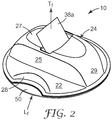
- FIG 2 shows an isometric view of dispenser 10 of Figure 1 assembled such that sheet 38a extends through the slot and is ready for dispensing.
- a portion of holding film 50 is exposed.
- the user wants to break the vacuum between the holding film and a work surface, the user lifts the exposed portion of the holding film.
- T f the user exerts a force on the dispenser by pulling on the sheet in the direction indicated generally by reference arrow, T f .
- the vacuum between the holding film and the work surface keeps the dispenser stationary allowing the user to remove the sheet with one hand. In other words, the user does not need to hold down the dispenser with his or her free hand while removing the sheet from the dispenser.
- the user can slide dispenser across a work surface. It is believed that this type of movement allows air that may be trapped between the holding film and the work surface to escape thereby increasing the vacuum.
- the dispenser can be used on horizontal and vertical work surfaces.
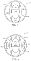
- Figure 3 is a top plan view of another dispenser 110 similar to the dispesner of Figure 1 , except that there are no cutouts in the upper or lower members.
- the upper member has two side portions 122 extending from opposing halves of the circular rim and a protrusion disposed therebetween.
- the protrusion includes two side walls 125 that extend from the side portion two sloping walls 129 that meet at the rim.
- a user can also break the suction of the holding film on the work surface by e.g., sliding the dispenser to an edge of the work surface to break the vacuum.
- Figure 4 is a top plan view of yet another dispenser 210 similar to the dispenser of Figure 1 , except that there are two cut outs, one on each side of side portions 222. A protrusion with two side walls 225 is disposed between the side portions. This particular design allows the user to break the suction on either side of the dispenser.
- the stacks shown in Figures 1 to 4 contain a plurality of elongated sheets releasably adhered to one another in a fan-fold configuration.
- Each sheet has a tab end portion, an adhesive end portion, and opposing first and second surfaces.
- the first surface is adhesive free and preferably writeable.
- the second surface includes a repositionable adhesive on its adhesive end portion, which is larger than the tab end portion and also transparent. If desired, the tab end portion may contain indicia and or may be brightly colored. If a sheet has a length L, the tab end portion is about 30 to 35% of the length while the adhesive end portion is about 65 to 70% of the sheet's length.
- the sheets are stacked such that for any two adjacent sheets, the tab end portion of one sheet lies at an opposing end of the stack relative to the next sheet.
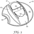
- Figure 5 shows an isometric view of another embodiment of another upper member 60 that can be used in the present invention.
- the upper member 60 is similar to the upper member 20 of Figure 1 , except that in top region 61 where slot 66 is disposed, two grooves 63 extend from each end of the slot. The grooves lie generally transverse to the slot along the length of the protrusion.
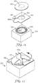
- FIG. 6 shows an exploded view of another dispenser of the present invention that is particularly suited for dispensing repositionable notes, such as Post-it® Notes commercially available from 3M Company.
- Such notes are paper based having a coating (typically a stripe) of repositionable adhesive across an edge of the note.
- the stripe of adhesive typically covers from 25% to 35% of the note's surface area.
- the dispenser includes an upper member 320 having a substantially box like shape with four side walls 325 disposed substantially orthogonal to one another and substantially orthogonal to a top 327.
- the sidewalls have top edge 325a and bottom edge 325b.
- a slot 326 is disposed on the top. The slot is sized to sufficiently wide to allow repositionable notes of desired width to be dispensed.
- the dispenser further includes substantially square lower member 330 having opposing interior surface 330a and exterior surface (not shown).
- the upper and lower members are integrally formed.
- Spring 332 disposed on the interior surface of the lower member, acts as the biasing mechanism to push stack of repositionable notes 338 against the inside surface of top 327.
- attachment mechanism 340 circular holding film 350 attaches to the exterior surface of the lower member. This particular embodiment shows that the geometry of the holding film can, but does not necessarily have to be similar to that of the lower member.
- Figure 7 shows an isometric view of dispenser 310 of Figure 6 assembled such that flag 338a extends through slot 326 and holding film 350 is attached to the lower member of the dispenser.
- the dispenser is measures 3.125 by 3.125 inch (7.9 by 7.9 cm) in length and width and has height of 11 ⁇ 2 inch (3.8 cm).
- a 3 inch (7.6 cm) diameter holding film and a 1 inch diameter (2.5 cm) circular double sided tape or cyanoacrylate adhesive is used to attach to the holding film and the lower member of the dispenser.
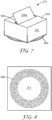
- Figure 8 shows a bottom plan view of the exterior surface of a lower member of yet another embodiment of the present invention.
- the exterior surface has a central planar area 331 for receiving the attachment mechanism.
- roughened region 332 Surrounding the central planar area is roughened region 332, which can be created by a variety of methods such as embossing or perforating the lower member.
- the roughened region includes a plurality of distinct raised dots.
- the roughened region can also result from applying a coating that would impart surface roughness to the exterior surface of the lower member. While this figure shows the roughened region as a circular pattern, other configurations and layouts can be used. For example, when using raised dots, they can be scattered throughout the exterior surface area of the lower member.
- the roughened region functions to reduce the contact surface area between the exterior surface of the lower member and the first surface of the holding film.
- the contact surface area between the second surface of the holding film to the work surface is larger than the contact surface area between the exterior surface of the lower member and the first surface of the holding film.
- Figure 9 shows a bottom plan view of another exemplary exterior surface 430b of lower member 430 having cut-out 431 that can be used in the present invention.
- the contact surface area between the exterior surface of the lower member and the first surface of the holding film has been reduced by use of holes 432.
- standoff bars 433 can also be used in addition to the holes.
- Figure 10 shows an isometric view of another exemplary dispenser where the dispenser of Figure 7 further includes an activation card 360 having a pull tab 360a.
- the pull tab can include pre-printed indicia (e.g., "Remove Before Using") instructing a consumer to remove the card before use.
- the activation card can be made from a variety of materials, including, e.g., paper and plastic film.
- the activation card lies between the holding film 350 and the exterior surface of the lower member, which in one embodiment, includes a roughened region like that shown in Figure 8 .
- Figure 11 shows an exploded view of the bottom of the dispenser of Figure 11 with holding film 350 having attachment mechanism 340 centrally located and shown in phantom.
- the activation card includes an aperture 364 sized and placed so as to accommodate the attachment mechanism.
- the aperture is generally slightly larger than the dimension of the attachment mechanism.
- the activation card further includes an angled slit 362 allowing for its installation to the dispenser 320. While the design of the activation card is particularly suited for the dispenser of Figure 7 , other designs can be used.
- the perimeter of the activation card is substantially the same size as the perimeter of the lower member and covers a portion, if not substantially all, of the roughened region 332 on the exterior surface of the lower member.
- the activation card is made from paper or polymeric film, is of square geometry having a side length of 3 inch, a central hole having a diameter of 1.5 inch, a slit length of 1 inch and a slit gap distance of 0.25 inch.
- the design for the activation card shown in Figure 11 can be made by die cutting the paper or polymeric film.
- Figure 12 schematically shows removing the activation card prior to using the dispenser.
- the pull tab generally in the direction indicated by the arrow
- the lifting of the activation card causes the holding film to curl away from exterior surface of the lower member.
- the activation card can be used in any dispenser.
- the holding films listed in Table 1 were then subjected to a test where tension force using an Instron machine using a cross head speed of 20 inch per minute.
- a three inch diameter circle of each type of film was taped using a one inch square double sided tape to a 3 inch circular shaped lower member of a dispenser similar to the one shown in Figure 1 .
- a one inch wide tape was attached to the top region of the dispenser, the tape functioning as a lead for the Instron jaw.
- the dispenser with the holding film was placed on a different work surfaces, such as panels of oak.
- the three types of work surfaces, all wood-based, tested included (a) cathedral cut oak veneer, (b) oak veneer with a polyurethane coating, and (c) an oak veneer with a lacquer coating.
- a cathedral cut oak veneer is one where the oak wood is sliced tangentially to the growth rings of the tree, thereby producing distinct peaks or spires in the grain pattern.
- the cathedral cut typically requires centering the wood grain to produce on the face of the veneer a substantially "V" figure resembling the spires of a cathedral.
- the cathedral cut veneer is the roughest.
- the amount of force needed to pull the dispenser off the work surface is then measured.
- the EPDM rubber consistently gave the highest force on all three types of work surface.
- the EDPM was the highest force values, followed by the urethane. As between the Santoprene, ECH, and PET, they all performed poorer than the urethane.
Landscapes
- Engineering & Computer Science (AREA)
- Mechanical Engineering (AREA)
- General Engineering & Computer Science (AREA)
- Details Of Rigid Or Semi-Rigid Containers (AREA)
- Containers And Packaging Bodies Having A Special Means To Remove Contents (AREA)
- Supports Or Holders For Household Use (AREA)
Applications Claiming Priority (5)
| Application Number | Priority Date | Filing Date | Title |
|---|---|---|---|
| US83076406P | 2006-07-14 | 2006-07-14 | |
| US83097906P | 2006-07-14 | 2006-07-14 | |
| US85162206P | 2006-10-13 | 2006-10-13 | |
| US86416906P | 2006-11-03 | 2006-11-03 | |
| PCT/US2007/073098 WO2008008742A1 (en) | 2006-07-14 | 2007-07-10 | Attachment system and dispensers used therewith |
Publications (3)
| Publication Number | Publication Date |
|---|---|
| EP2040933A1 EP2040933A1 (en) | 2009-04-01 |
| EP2040933A4 EP2040933A4 (en) | 2012-12-05 |
| EP2040933B1 true EP2040933B1 (en) | 2019-10-23 |
Family
ID=38923555
Family Applications (1)
| Application Number | Title | Priority Date | Filing Date |
|---|---|---|---|
| EP07799432.5A Active EP2040933B1 (en) | 2006-07-14 | 2007-07-10 | Dispenser with attachment system |
Country Status (6)
| Country | Link |
|---|---|
| US (2) | US8261937B2 (enExample) |
| EP (1) | EP2040933B1 (enExample) |
| JP (2) | JP5890084B2 (enExample) |
| KR (1) | KR101476457B1 (enExample) |
| CN (1) | CN101489802B (enExample) |
| WO (1) | WO2008008742A1 (enExample) |
Families Citing this family (27)
| Publication number | Priority date | Publication date | Assignee | Title |
|---|---|---|---|---|
| US20090108151A1 (en) * | 2007-10-26 | 2009-04-30 | Carnevali Jeffrey D | Transparent suction cup mounting platform |
| USD661740S1 (en) * | 2010-04-21 | 2012-06-12 | Jour David C T | Notepaper dispenser |
| USD683397S1 (en) | 2010-04-21 | 2013-05-28 | Avery Dennison Corporation | Pad of labels |
| US8528731B2 (en) | 2010-04-21 | 2013-09-10 | Ccl Label, Inc. | Labels, related pads thereof, and related methods |
| USD661741S1 (en) * | 2010-09-16 | 2012-06-12 | Jour David C T | Notepaper dispenser |
| US20120145744A1 (en) * | 2010-12-08 | 2012-06-14 | 3M Innovative Properties Company | Liquid dispenser |
| US8944279B2 (en) * | 2010-12-22 | 2015-02-03 | Kimberly-Clark Worldwide, Inc. | Wet wipe dispenser with improved arc-shaped dispensing partition |
| WO2013101808A1 (en) | 2011-12-28 | 2013-07-04 | 3M Innovative Properties Company | Easily sheet dispensing note pad |
| JP2013217475A (ja) * | 2012-04-11 | 2013-10-24 | Ferro-Carbon Enterprise Co Ltd | 吸盤 |
| ITMI20121329A1 (it) * | 2012-07-30 | 2014-01-31 | Prora Millenote S R L | Erogatore |
| DK178077B1 (en) * | 2013-11-18 | 2015-05-04 | Easystrap Holding Aps | Anordning til montering på overfladen af et køretøjs karrosseri |
| USD736315S1 (en) * | 2014-06-08 | 2015-08-11 | David C. T. Jour | Memo paper dispenser |
| USD736316S1 (en) * | 2014-06-09 | 2015-08-11 | David C. T. Jour | Memo paper dispenser |
| JP2016055890A (ja) * | 2014-09-09 | 2016-04-21 | 日本製紙クレシア株式会社 | 包装体 |
| US9181974B1 (en) * | 2015-01-26 | 2015-11-10 | Avery Aerospace Corporation | Suction cup attachment device |
| EP3419834B1 (en) * | 2016-02-22 | 2020-12-23 | 3M Innovative Properties Company | Assembly for dispensing full adhesive notes |
| USD862601S1 (en) | 2016-07-07 | 2019-10-08 | Ccl Label, Inc. | Carrier assembly |
| CN109788859A (zh) * | 2016-08-10 | 2019-05-21 | 爱德玛国际股份有限公司 | 供食垫 |
| CN107512472B (zh) * | 2017-09-14 | 2023-02-10 | 国网吉林省电力有限公司电力科学研究院 | 粉尘采样用无尘滤膜储备盒及其使用方法 |
| FR3073766B1 (fr) * | 2017-11-22 | 2019-10-25 | Coval | Dispositif de prehension avec surveillance de son etat de fonctionnement |
| USD876316S1 (en) | 2018-05-23 | 2020-02-25 | Annex Products Pty. Ltd. | Car mount |
| US10649492B2 (en) | 2018-05-31 | 2020-05-12 | Annex Products Pty. Ltd. | Mount for handheld electronic devices |
| US11498747B2 (en) * | 2020-01-08 | 2022-11-15 | Bobrick Washroom Equipment, Inc. | Liner dispenser |
| DE212021000309U1 (de) * | 2020-02-10 | 2022-10-19 | 3M Innovative Properties Company | Abgabestruktur und Abgabeanordnung |
| CN113844751A (zh) * | 2021-08-09 | 2021-12-28 | 贺琼 | 一种糖尿病血糖检测试纸保存盒 |
| US20230240396A1 (en) * | 2022-01-30 | 2023-08-03 | Jesse GARLAND | Contactless hand covering |
| US20240002134A1 (en) * | 2023-09-18 | 2024-01-04 | Leonard J. Dufrene | Electrical Wire Compression Connector Dispensing Container |
Family Cites Families (40)
| Publication number | Priority date | Publication date | Assignee | Title |
|---|---|---|---|---|
| US3068055A (en) * | 1960-05-24 | 1962-12-11 | Marie A Lenzi | Household napkin holder and dispenser |
| US3381853A (en) | 1966-11-22 | 1968-05-07 | Litton Business Systems Inc | Strip dispenser |
| US4003538A (en) * | 1975-09-02 | 1977-01-18 | Frye Bruce J | Article holding device |
| US4390576A (en) * | 1980-09-19 | 1983-06-28 | Physical Systems, Inc. | Adhesive attachment assembly |
| US4778702A (en) * | 1985-09-04 | 1988-10-18 | Physical Systems, Inc. | Adhesive attachment and mounting fixture |
| US4907825A (en) * | 1987-06-03 | 1990-03-13 | Minnesota Mining And Manufacturing Company | Sheet and dispenser package therefor |
| US4828303A (en) | 1987-12-18 | 1989-05-09 | Soria Rolando C | Automobile body protection apparatus and method |
| JPH02195098A (ja) | 1988-08-17 | 1990-08-01 | Bruno Gruber | 保持部材から成る吸着保留保持手段 |
| US5086946A (en) * | 1990-12-10 | 1992-02-11 | Minnesota Mining And Manufacturing Company | Sheet stack and dispenser package therefor |
| US5087005A (en) * | 1991-02-12 | 1992-02-11 | Holoff Richard S | Twist-cam suction cup assembly |
| US5180132A (en) * | 1991-11-22 | 1993-01-19 | Pearson Scott A | Self-setting suction holder device |
| DE69424804T2 (de) * | 1993-05-18 | 2001-01-11 | Minnesota Mining And Mfg. Co., Saint Paul | Blattspender mit wahlweiser stütz- oder befestigungsvorrichtung |
| US5358141A (en) * | 1993-05-18 | 1994-10-25 | Minnesota Mining And Manufacturing Company | Support or attachment means for a sheet dispenser |
| JP2600644Y2 (ja) * | 1993-06-24 | 1999-10-18 | 順彦 佐藤 | 吸盤用補助板 |
| US5411168A (en) | 1993-08-03 | 1995-05-02 | Minnesota Mining And Manufacturing Company | Sheet dispenser and dispenser subassemblies |
| US5397117A (en) | 1993-10-05 | 1995-03-14 | Minnesota Mining And Manufacturing Company | Sheet dispenser |
| US5785820A (en) * | 1994-01-07 | 1998-07-28 | Startec Ventures, Inc. | On-site manufacture of ultra-high-purity hydrofluoric acid for semiconductor processing |
| US5714215A (en) | 1994-03-14 | 1998-02-03 | Sheffield; Douglas | Unitary flexible information presentation board having self-suction |
| JP2687913B2 (ja) * | 1995-01-12 | 1997-12-08 | コクヨ株式会社 | 付箋紙収納容器 |
| JPH08230871A (ja) * | 1995-02-22 | 1996-09-10 | Hiroshi Nakanishi | ペーパーロール用容器及びペーパーロール包装品 |
| JPH11503700A (ja) | 1995-04-20 | 1999-03-30 | ミネソタ・マイニング・アンド・マニュファクチャリング・カンパニー | ディスペンサパッケージ |
| DE69610216T2 (de) | 1995-11-20 | 2001-04-26 | Anthony S. Hiscock | Lösbare montagevorrichtung |
| US5794815A (en) * | 1996-06-19 | 1998-08-18 | Minnesota Mining And Manufacturing Company | Dispensers with optional support or attachment means |
| JP3669802B2 (ja) * | 1997-01-31 | 2005-07-13 | 信越ポリマー株式会社 | 吸着性表面を有するシート状部材 |
| USD396492S (en) | 1997-08-22 | 1998-07-28 | Minnesota Mining And Manufacturing Company | Sheet dispenser |
| USD396247S (en) | 1997-08-22 | 1998-07-21 | Minnesota Mining And Manufacturing Company | Sheet dispenser |
| US6972141B1 (en) * | 1997-12-12 | 2005-12-06 | 3M Innovative Properties Company | Removable adhesive tape laminate and separable fastener |
| US6053356A (en) * | 1998-01-30 | 2000-04-25 | Michael J. Emoff | Coupon dispenser with suction cup mounting |
| AU2656199A (en) | 1998-02-18 | 1999-09-06 | Minnesota Mining And Manufacturing Company | Publication inserts |
| US6364099B2 (en) * | 1999-12-21 | 2002-04-02 | Michael J. Emoff | Coupon dispenser assembly and shroud |
| JP3071585U (ja) * | 2000-03-08 | 2000-09-14 | シーレックス株式会社 | 付箋紙収容箱 |
| US6858288B2 (en) * | 2000-05-23 | 2005-02-22 | Oji Paper Co., Ltd. | Wrap film |
| JP4730864B2 (ja) * | 2000-06-13 | 2011-07-20 | 旭化成ケミカルズ株式会社 | 吸引に用いるシート及びそれを用いた装置 |
| FR2814150B1 (fr) | 2000-09-21 | 2003-01-24 | Oreal | Dispositif pour la fixation reversible d'un recipient sur un support et recipient equipe d'un tel dispositif |
| JP2003117881A (ja) * | 2001-10-16 | 2003-04-23 | Nitomuzu:Kk | テープディスペンサ |
| US7186908B2 (en) * | 2003-08-27 | 2007-03-06 | Hodesh Mitchell J | Stringed musical instrument pick with inert adhesion |
| US20050109790A1 (en) * | 2003-11-25 | 2005-05-26 | Nick Hsu | Window tabs storage case |
| USD502740S1 (en) | 2004-02-26 | 2005-03-08 | Thomas Direct Sales, Inc. | Flag dispenser |
| US7121924B2 (en) * | 2004-04-20 | 2006-10-17 | 3M Innovative Properties Company | Abrasive articles, and methods of making and using the same |
| JP2006257191A (ja) * | 2005-03-16 | 2006-09-28 | Sumitomo Chemical Co Ltd | 粘着フィルムまたは粘着シート、その製造方法およびそれからなる粘着製品 |
-
2007
- 2007-07-10 JP JP2009520893A patent/JP5890084B2/ja not_active Expired - Fee Related
- 2007-07-10 US US11/775,276 patent/US8261937B2/en active Active
- 2007-07-10 KR KR1020097000634A patent/KR101476457B1/ko not_active Expired - Fee Related
- 2007-07-10 CN CN200780026661XA patent/CN101489802B/zh not_active Expired - Fee Related
- 2007-07-10 EP EP07799432.5A patent/EP2040933B1/en active Active
- 2007-07-10 WO PCT/US2007/073098 patent/WO2008008742A1/en not_active Ceased
-
2012
- 2012-08-23 US US13/592,681 patent/US20120321852A1/en not_active Abandoned
-
2013
- 2013-12-12 JP JP2013257357A patent/JP5981413B2/ja not_active Expired - Fee Related
Also Published As
| Publication number | Publication date |
|---|---|
| US8261937B2 (en) | 2012-09-11 |
| CN101489802A (zh) | 2009-07-22 |
| EP2040933A1 (en) | 2009-04-01 |
| US20120321852A1 (en) | 2012-12-20 |
| KR20090042234A (ko) | 2009-04-29 |
| JP5981413B2 (ja) | 2016-08-31 |
| CN101489802B (zh) | 2011-01-26 |
| JP2014061951A (ja) | 2014-04-10 |
| EP2040933A4 (en) | 2012-12-05 |
| US20080011626A1 (en) | 2008-01-17 |
| JP2009543744A (ja) | 2009-12-10 |
| KR101476457B1 (ko) | 2014-12-24 |
| JP5890084B2 (ja) | 2016-03-22 |
| WO2008008742A1 (en) | 2008-01-17 |
Similar Documents
| Publication | Publication Date | Title |
|---|---|---|
| EP2040933B1 (en) | Dispenser with attachment system | |
| JP3899382B2 (ja) | 圧縮可能なシートのディスペンサー | |
| KR0119544Y1 (ko) | 시이트 어셈블리의 스택 | |
| US5997229A (en) | Screw cover and method | |
| KR101455414B1 (ko) | 마킹 장치 | |
| KR101203374B1 (ko) | 선택적으로 활성화되는 접착제를 갖는 시트 | |
| WO2000029224A2 (en) | Tape strip pads and dispenser and method of dispensing individual tape strips | |
| WO2010056975A1 (en) | Stack of adhesive labels and method for applying same to substrates | |
| CN101374742A (zh) | 分配器组件 | |
| CA2603455C (en) | Tape dispenser | |
| US6688488B2 (en) | Blister spring for pop-up sheet material dispenser | |
| EP3419834B1 (en) | Assembly for dispensing full adhesive notes | |
| JP2000502641A (ja) | 収納部付き補充可能なシートディスペンサー | |
| JP2008501550A (ja) | 接着クリップアセンブリ | |
| EP2043879B1 (en) | Open top dispenser | |
| WO2010107898A2 (en) | Positionable masking article | |
| KR20100092514A (ko) | 양면 접착 테이프에 돌출 탭을 적용하기 위한 장치 및 사용 방법 | |
| CA1257622A (en) | Notepaper dispensing tray | |
| US20120168456A1 (en) | Pop-up label dispenser and method of use | |
| CA1102755A (en) | Partially wall abutting cantilever mounting twin bladed tape dispenser |
Legal Events
| Date | Code | Title | Description |
|---|---|---|---|
| PUAI | Public reference made under article 153(3) epc to a published international application that has entered the european phase |
Free format text: ORIGINAL CODE: 0009012 |
|
| 17P | Request for examination filed |
Effective date: 20090126 |
|
| AK | Designated contracting states |
Kind code of ref document: A1 Designated state(s): AT BE BG CH CY CZ DE DK EE ES FI FR GB GR HU IE IS IT LI LT LU LV MC MT NL PL PT RO SE SI SK TR |
|
| AX | Request for extension of the european patent |
Extension state: AL BA HR MK RS |
|
| DAX | Request for extension of the european patent (deleted) | ||
| A4 | Supplementary search report drawn up and despatched |
Effective date: 20121105 |
|
| RIC1 | Information provided on ipc code assigned before grant |
Ipc: B65D 83/08 20060101ALI20121029BHEP Ipc: B42D 5/00 20060101AFI20121029BHEP Ipc: F16B 47/00 20060101ALN20121029BHEP |
|
| STAA | Information on the status of an ep patent application or granted ep patent |
Free format text: STATUS: EXAMINATION IS IN PROGRESS |
|
| 17Q | First examination report despatched |
Effective date: 20180815 |
|
| GRAP | Despatch of communication of intention to grant a patent |
Free format text: ORIGINAL CODE: EPIDOSNIGR1 |
|
| STAA | Information on the status of an ep patent application or granted ep patent |
Free format text: STATUS: GRANT OF PATENT IS INTENDED |
|
| INTG | Intention to grant announced |
Effective date: 20190507 |
|
| GRAS | Grant fee paid |
Free format text: ORIGINAL CODE: EPIDOSNIGR3 |
|
| GRAA | (expected) grant |
Free format text: ORIGINAL CODE: 0009210 |
|
| STAA | Information on the status of an ep patent application or granted ep patent |
Free format text: STATUS: THE PATENT HAS BEEN GRANTED |
|
| AK | Designated contracting states |
Kind code of ref document: B1 Designated state(s): AT BE BG CH CY CZ DE DK EE ES FI FR GB GR HU IE IS IT LI LT LU LV MC MT NL PL PT RO SE SI SK TR |
|
| REG | Reference to a national code |
Ref country code: GB Ref legal event code: FG4D |
|
| REG | Reference to a national code |
Ref country code: CH Ref legal event code: EP |
|
| REG | Reference to a national code |
Ref country code: IE Ref legal event code: FG4D |
|
| REG | Reference to a national code |
Ref country code: DE Ref legal event code: R096 Ref document number: 602007059397 Country of ref document: DE |
|
| REG | Reference to a national code |
Ref country code: AT Ref legal event code: REF Ref document number: 1193236 Country of ref document: AT Kind code of ref document: T Effective date: 20191115 |
|
| REG | Reference to a national code |
Ref country code: NL Ref legal event code: MP Effective date: 20191023 |
|
| REG | Reference to a national code |
Ref country code: LT Ref legal event code: MG4D |
|
| PG25 | Lapsed in a contracting state [announced via postgrant information from national office to epo] |
Ref country code: PT Free format text: LAPSE BECAUSE OF FAILURE TO SUBMIT A TRANSLATION OF THE DESCRIPTION OR TO PAY THE FEE WITHIN THE PRESCRIBED TIME-LIMIT Effective date: 20200224 Ref country code: FI Free format text: LAPSE BECAUSE OF FAILURE TO SUBMIT A TRANSLATION OF THE DESCRIPTION OR TO PAY THE FEE WITHIN THE PRESCRIBED TIME-LIMIT Effective date: 20191023 Ref country code: SE Free format text: LAPSE BECAUSE OF FAILURE TO SUBMIT A TRANSLATION OF THE DESCRIPTION OR TO PAY THE FEE WITHIN THE PRESCRIBED TIME-LIMIT Effective date: 20191023 Ref country code: LV Free format text: LAPSE BECAUSE OF FAILURE TO SUBMIT A TRANSLATION OF THE DESCRIPTION OR TO PAY THE FEE WITHIN THE PRESCRIBED TIME-LIMIT Effective date: 20191023 Ref country code: NL Free format text: LAPSE BECAUSE OF FAILURE TO SUBMIT A TRANSLATION OF THE DESCRIPTION OR TO PAY THE FEE WITHIN THE PRESCRIBED TIME-LIMIT Effective date: 20191023 Ref country code: PL Free format text: LAPSE BECAUSE OF FAILURE TO SUBMIT A TRANSLATION OF THE DESCRIPTION OR TO PAY THE FEE WITHIN THE PRESCRIBED TIME-LIMIT Effective date: 20191023 Ref country code: GR Free format text: LAPSE BECAUSE OF FAILURE TO SUBMIT A TRANSLATION OF THE DESCRIPTION OR TO PAY THE FEE WITHIN THE PRESCRIBED TIME-LIMIT Effective date: 20200124 Ref country code: BG Free format text: LAPSE BECAUSE OF FAILURE TO SUBMIT A TRANSLATION OF THE DESCRIPTION OR TO PAY THE FEE WITHIN THE PRESCRIBED TIME-LIMIT Effective date: 20200123 Ref country code: LT Free format text: LAPSE BECAUSE OF FAILURE TO SUBMIT A TRANSLATION OF THE DESCRIPTION OR TO PAY THE FEE WITHIN THE PRESCRIBED TIME-LIMIT Effective date: 20191023 Ref country code: ES Free format text: LAPSE BECAUSE OF FAILURE TO SUBMIT A TRANSLATION OF THE DESCRIPTION OR TO PAY THE FEE WITHIN THE PRESCRIBED TIME-LIMIT Effective date: 20191023 |
|
| PG25 | Lapsed in a contracting state [announced via postgrant information from national office to epo] |
Ref country code: IS Free format text: LAPSE BECAUSE OF FAILURE TO SUBMIT A TRANSLATION OF THE DESCRIPTION OR TO PAY THE FEE WITHIN THE PRESCRIBED TIME-LIMIT Effective date: 20200224 |
|
| REG | Reference to a national code |
Ref country code: DE Ref legal event code: R097 Ref document number: 602007059397 Country of ref document: DE |
|
| PG2D | Information on lapse in contracting state deleted |
Ref country code: IS |
|
| PG25 | Lapsed in a contracting state [announced via postgrant information from national office to epo] |
Ref country code: EE Free format text: LAPSE BECAUSE OF FAILURE TO SUBMIT A TRANSLATION OF THE DESCRIPTION OR TO PAY THE FEE WITHIN THE PRESCRIBED TIME-LIMIT Effective date: 20191023 Ref country code: DK Free format text: LAPSE BECAUSE OF FAILURE TO SUBMIT A TRANSLATION OF THE DESCRIPTION OR TO PAY THE FEE WITHIN THE PRESCRIBED TIME-LIMIT Effective date: 20191023 Ref country code: CZ Free format text: LAPSE BECAUSE OF FAILURE TO SUBMIT A TRANSLATION OF THE DESCRIPTION OR TO PAY THE FEE WITHIN THE PRESCRIBED TIME-LIMIT Effective date: 20191023 Ref country code: RO Free format text: LAPSE BECAUSE OF FAILURE TO SUBMIT A TRANSLATION OF THE DESCRIPTION OR TO PAY THE FEE WITHIN THE PRESCRIBED TIME-LIMIT Effective date: 20191023 Ref country code: IS Free format text: LAPSE BECAUSE OF FAILURE TO SUBMIT A TRANSLATION OF THE DESCRIPTION OR TO PAY THE FEE WITHIN THE PRESCRIBED TIME-LIMIT Effective date: 20200223 |
|
| REG | Reference to a national code |
Ref country code: AT Ref legal event code: MK05 Ref document number: 1193236 Country of ref document: AT Kind code of ref document: T Effective date: 20191023 |
|
| PLBE | No opposition filed within time limit |
Free format text: ORIGINAL CODE: 0009261 |
|
| STAA | Information on the status of an ep patent application or granted ep patent |
Free format text: STATUS: NO OPPOSITION FILED WITHIN TIME LIMIT |
|
| PG25 | Lapsed in a contracting state [announced via postgrant information from national office to epo] |
Ref country code: IT Free format text: LAPSE BECAUSE OF FAILURE TO SUBMIT A TRANSLATION OF THE DESCRIPTION OR TO PAY THE FEE WITHIN THE PRESCRIBED TIME-LIMIT Effective date: 20191023 Ref country code: SK Free format text: LAPSE BECAUSE OF FAILURE TO SUBMIT A TRANSLATION OF THE DESCRIPTION OR TO PAY THE FEE WITHIN THE PRESCRIBED TIME-LIMIT Effective date: 20191023 |
|
| 26N | No opposition filed |
Effective date: 20200724 |
|
| PGFP | Annual fee paid to national office [announced via postgrant information from national office to epo] |
Ref country code: DE Payment date: 20200630 Year of fee payment: 14 |
|
| PG25 | Lapsed in a contracting state [announced via postgrant information from national office to epo] |
Ref country code: AT Free format text: LAPSE BECAUSE OF FAILURE TO SUBMIT A TRANSLATION OF THE DESCRIPTION OR TO PAY THE FEE WITHIN THE PRESCRIBED TIME-LIMIT Effective date: 20191023 Ref country code: SI Free format text: LAPSE BECAUSE OF FAILURE TO SUBMIT A TRANSLATION OF THE DESCRIPTION OR TO PAY THE FEE WITHIN THE PRESCRIBED TIME-LIMIT Effective date: 20191023 |
|
| PG25 | Lapsed in a contracting state [announced via postgrant information from national office to epo] |
Ref country code: MC Free format text: LAPSE BECAUSE OF FAILURE TO SUBMIT A TRANSLATION OF THE DESCRIPTION OR TO PAY THE FEE WITHIN THE PRESCRIBED TIME-LIMIT Effective date: 20191023 |
|
| REG | Reference to a national code |
Ref country code: CH Ref legal event code: PL |
|
| GBPC | Gb: european patent ceased through non-payment of renewal fee |
Effective date: 20200710 |
|
| REG | Reference to a national code |
Ref country code: BE Ref legal event code: MM Effective date: 20200731 |
|
| PG25 | Lapsed in a contracting state [announced via postgrant information from national office to epo] |
Ref country code: FR Free format text: LAPSE BECAUSE OF NON-PAYMENT OF DUE FEES Effective date: 20200731 Ref country code: GB Free format text: LAPSE BECAUSE OF NON-PAYMENT OF DUE FEES Effective date: 20200710 Ref country code: LU Free format text: LAPSE BECAUSE OF NON-PAYMENT OF DUE FEES Effective date: 20200710 Ref country code: LI Free format text: LAPSE BECAUSE OF NON-PAYMENT OF DUE FEES Effective date: 20200731 Ref country code: CH Free format text: LAPSE BECAUSE OF NON-PAYMENT OF DUE FEES Effective date: 20200731 |
|
| PG25 | Lapsed in a contracting state [announced via postgrant information from national office to epo] |
Ref country code: BE Free format text: LAPSE BECAUSE OF NON-PAYMENT OF DUE FEES Effective date: 20200731 |
|
| PG25 | Lapsed in a contracting state [announced via postgrant information from national office to epo] |
Ref country code: IE Free format text: LAPSE BECAUSE OF NON-PAYMENT OF DUE FEES Effective date: 20200710 |
|
| REG | Reference to a national code |
Ref country code: DE Ref legal event code: R119 Ref document number: 602007059397 Country of ref document: DE |
|
| PG25 | Lapsed in a contracting state [announced via postgrant information from national office to epo] |
Ref country code: DE Free format text: LAPSE BECAUSE OF NON-PAYMENT OF DUE FEES Effective date: 20220201 |
|
| PG25 | Lapsed in a contracting state [announced via postgrant information from national office to epo] |
Ref country code: TR Free format text: LAPSE BECAUSE OF FAILURE TO SUBMIT A TRANSLATION OF THE DESCRIPTION OR TO PAY THE FEE WITHIN THE PRESCRIBED TIME-LIMIT Effective date: 20191023 Ref country code: MT Free format text: LAPSE BECAUSE OF FAILURE TO SUBMIT A TRANSLATION OF THE DESCRIPTION OR TO PAY THE FEE WITHIN THE PRESCRIBED TIME-LIMIT Effective date: 20191023 Ref country code: CY Free format text: LAPSE BECAUSE OF FAILURE TO SUBMIT A TRANSLATION OF THE DESCRIPTION OR TO PAY THE FEE WITHIN THE PRESCRIBED TIME-LIMIT Effective date: 20191023 |