EP2040530B1 - Schneidkörper - Google Patents
Schneidkörper Download PDFInfo
- Publication number
- EP2040530B1 EP2040530B1 EP07785837A EP07785837A EP2040530B1 EP 2040530 B1 EP2040530 B1 EP 2040530B1 EP 07785837 A EP07785837 A EP 07785837A EP 07785837 A EP07785837 A EP 07785837A EP 2040530 B1 EP2040530 B1 EP 2040530B1
- Authority
- EP
- European Patent Office
- Prior art keywords
- cutting element
- element according
- rear side
- body part
- reinforcing
- Prior art date
- Legal status (The legal status is an assumption and is not a legal conclusion. Google has not performed a legal analysis and makes no representation as to the accuracy of the status listed.)
- Active
Links
Images
Classifications
-
- B—PERFORMING OPERATIONS; TRANSPORTING
- B02—CRUSHING, PULVERISING, OR DISINTEGRATING; PREPARATORY TREATMENT OF GRAIN FOR MILLING
- B02C—CRUSHING, PULVERISING, OR DISINTEGRATING IN GENERAL; MILLING GRAIN
- B02C18/00—Disintegrating by knives or other cutting or tearing members which chop material into fragments
- B02C18/06—Disintegrating by knives or other cutting or tearing members which chop material into fragments with rotating knives
- B02C18/16—Details
- B02C18/18—Knives; Mountings thereof
-
- A—HUMAN NECESSITIES
- A01—AGRICULTURE; FORESTRY; ANIMAL HUSBANDRY; HUNTING; TRAPPING; FISHING
- A01B—SOIL WORKING IN AGRICULTURE OR FORESTRY; PARTS, DETAILS, OR ACCESSORIES OF AGRICULTURAL MACHINES OR IMPLEMENTS, IN GENERAL
- A01B33/00—Tilling implements with rotary driven tools, e.g. in combination with fertiliser distributors or seeders, with grubbing chains, with sloping axles, with driven discs
- A01B33/08—Tools; Details, e.g. adaptations of transmissions or gearings
-
- A—HUMAN NECESSITIES
- A01—AGRICULTURE; FORESTRY; ANIMAL HUSBANDRY; HUNTING; TRAPPING; FISHING
- A01F—PROCESSING OF HARVESTED PRODUCE; HAY OR STRAW PRESSES; DEVICES FOR STORING AGRICULTURAL OR HORTICULTURAL PRODUCE
- A01F29/00—Cutting apparatus specially adapted for cutting hay, straw or the like
- A01F29/09—Details
- A01F29/095—Mounting or adjusting of knives
-
- A—HUMAN NECESSITIES
- A01—AGRICULTURE; FORESTRY; ANIMAL HUSBANDRY; HUNTING; TRAPPING; FISHING
- A01G—HORTICULTURE; CULTIVATION OF VEGETABLES, FLOWERS, RICE, FRUIT, VINES, HOPS OR SEAWEED; FORESTRY; WATERING
- A01G23/00—Forestry
- A01G23/02—Transplanting, uprooting, felling or delimbing trees
- A01G23/06—Uprooting or pulling up trees; Extracting or eliminating stumps
- A01G23/067—Uprooting or pulling up trees; Extracting or eliminating stumps by comminuting the tree stumps
-
- A—HUMAN NECESSITIES
- A01—AGRICULTURE; FORESTRY; ANIMAL HUSBANDRY; HUNTING; TRAPPING; FISHING
- A01G—HORTICULTURE; CULTIVATION OF VEGETABLES, FLOWERS, RICE, FRUIT, VINES, HOPS OR SEAWEED; FORESTRY; WATERING
- A01G3/00—Cutting implements specially adapted for horticultural purposes; Delimbing standing trees
- A01G3/002—Cutting implements specially adapted for horticultural purposes; Delimbing standing trees for comminuting plant waste
Definitions
- the invention relates to a cutting body for comminuting organic matter, organic materials, soils, vegetable crops od; Like., In particular for mulching, shredding and hacking, which is fixedly or detachably connectable with a crushing rotor, wherein the cutting body is connectable to a base member by means of a fastener, wherein the rotor fixedly connected to the base part has a corresponding edge, with at least one facing away from the cutting edge back / n of the cutting body for power transmission is engaged, and the cutting body forms a blade holder, protrude from the body part two parallel legs with holes for fittings, bolts, etc. and between the two legs another back is formed.
- Such cutting bodies are often on cylindrical rotors for the formation of cutting body surfaces Processing of organic materials, for processing soils, mulching, shredding, etc.
- a device of this kind is called Schlegel from the DE 94 02 062 U1 for equipment for the treatment of organic waste materials such.
- the flail consists of a holder connected to a rotating shaft and a shaft with the latter via a screw and clamp connection form-fitting and non-positively connected cutting part.
- an incisor which is held on the outer surface of a rotating cutter and is suitable for cutting down, mulching and grinding trees.
- the incisor consists of a front side cutting body with cutting tips, sides and back.
- the cutting body is mounted relative to the rotary cutter such that two of the three cutting tips remain in a reduced carrying position while a third of the three cutting tips is in a cutting position to cut trees.
- a roller-shaped cutting body which on the Scheid stressesober Design projecting base parts has, with each base part, at least one cutting plate carrying blade holder is connectable, wherein the blade holder is connectable to the base member by means of a rotary bearing, wherein the axis of the rotary bearing parallel or at an angle is aligned with the axis of rotation of the cutting body and the rotation between the blade holder and the base part is limited by means of a stop of the cutter holder or the base member against the direction of rotation of the cutting body.
- the present invention is therefore an object of the invention to provide a cutting body of the type mentioned, in which the service life significantly increased during operation and wear is minimized and the manufacturing cost to be minimized in reducing the total weight.
- a force application and power transmission to its holding part or the rotor should be optimized.
- the cutting body should be securely and stably connected to the rotor.
- the body part of the blade holder forms a reinforcing profile below the cutting edge.
- This reinforcing profile simultaneously strengthens the area below the cutting edge, in which a large part of the cutting forces must be absorbed and forms at the same time recording, as well as Auflagerung for power transmission via its back to the base part.
- V-like grooves, semicircular oval grooves are provided within the back of the reinforcing projection, in which fit correspondingly corresponding end faces of the flanks of the base part. In this way, a lateral stabilization of the cutting body as well as a vibration behavior relative to the base part and rotor is also significantly reduced.
- the back of the reinforcing profile and the back of the body part between the two legs preferably include a very obtuse angle ⁇ , so that it is ensured that the cutting body mounted on the plate-like base part, fixed with a bolt, screw od. Like. In the region of the legs can not move up or down. In this way, due to the geometric shape of the rear sides of the body part and the reinforcing projection, an additional mechanical anti-rotation protection against pivoting about a bolt or screw connection is ensured. This should also be within the scope of the present invention.
- corresponding chip-rejecting surfaces can be provided above the cutting edge in the body part. These may also be provided in a front side of the reinforcing projection below the cutting edge.
- the side surfaces of the reinforcing projection starting from the front side and cutting edge tapering towards the rear at an acute angle Y.
- the cutting edge itself is kept free via the geometric shape of the reinforcing projection, so that friction is reduced overall during operation and during use, thus reducing heating and tempering of the cutting body in use.
- the lateral limbs are provided on their outer upper side with corresponding reinforcing profiles which extend in an annular manner around the region of the bore and protrude outward in a star-like manner, one of the reinforcing profiles extending into the region of the Body part extends to ensure additional stability.
- the legs can be conically tapered, starting from the body part to the bore formed in order to create a weight-reducing cutting body while maintaining high absorption forces and stability.
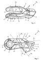
- a cutting body R 1 according to the invention has a blade holder 1 which accommodates at least one cutting edge 2 on a blade shoulder 3 in a front region, which blade is fixedly or releasably connected to the blade holder 1.
- the blade holder 1 essentially consists of a body part 4, from which protrude two mutually spaced trained leg 5.1, 5.2, wherein the inner surfaces 6 are formed parallel to each other.
- the two legs 5.1, 5.2, starting from the body part 4 to the bore 7.1, 7.2 taper slightly in thickness.
- annular reinforcements 9 are preferably provided around the bore 7.1, whereby a reinforcement of the annular reinforcement goes into the blade holder 1 or the body part 4.
- a cutting body R 1 is created, which is reduced in weight and at the same time by the correspondingly formed reinforcing profiles 9 a leg 5.1, 5.2 creates, which withstands very high loads.
- chip-deflecting surfaces 10 are formed from the body part 4 of the cutting-edge holder, which preferably extend at an acute angle.
- a reinforcing projection 11 is formed, which has a plurality of functions.
- chip-rejecting surfaces 10 which adapt approximately to the shape of the cutting edge 2.
- the reinforcing projection 11 formed from the body part 4 at the bottom, projects beyond the legs 5.1, 5.2 and forms a reinforcement for the force absorption of the forces which occur in the region of the cutting edge 2.
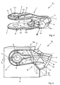
- a rear side 13 of the reinforcing projection 11 as a contact surface for a base part 14, which is the receptacle of the cutting body R 1 , as for example in FIG FIG. 4 is shown, serves.
- the two legs 5.1, 5.2 overlap the base part 14.
- a further rear side 15 is formed, which is also the system and power transmission to the correspondingly shaped base part 14, as it is in FIG. 4 is indicated serves.
- the base member 14 is plate-like and has corresponding flanks 16, and a corresponding bore 17 which are aligned when placing the cutter body R 1 and the spreading of the two legs 5.1, 5.2, wherein the back 15 of the body part 4 and the back 13 of the reinforcing projection 11 with the respective flanks 16 of the base part 4 preferably come into positive contact with the plant.
- flanks 16 of the base part 4 are adapted according to the geometry of the rear sides 13 and 15 of the reinforcing profile 11 and body part 4.
- the back 13 of the reinforcing profile 11 relative to a longitudinal axis A L of the cutting body R 1 is formed at an obtuse angle of about 90 ° to 160 °, preferably 125 °.
- the back 13 of the reinforcing projection 11 relative to the back 15 of the body part 4 also form at an obtuse angle form, wherein the angle of about 125 ° to 175 °, preferably 150 ° is selected.
- the longitudinal axis A L is viewed approximately centrally in the longitudinal direction through the legs 5.1, 5.2 as approximately bisector.
- corresponding side surfaces 18 of the reinforcing projection 8 are tapered starting from the front side 12 to the rear side 13 and preferably tapers tapered at an acute angle.
- the side surfaces 18 of the reinforcing projection 11 form an acute angle of about 15 ° to 35 °, preferably 25 °.
- the backs 13 and / or 15 of the reinforcing profile 11 and the body part 4 with a profiling 19, as shown in FIG. 3 is indicated, are provided.
- the profiles 19 may be groove-like, as angled grooves, V-like, oval-like, triangular grooves negative in the backs 13, 15th be formed or protrude as positive in appropriate form.
- the corresponding front sides of the flanks 16 of the base part are then shaped, so that the rear sides 13 and 15 of the reinforcing profile 11 and body part 4 fit flush against the base part 14 in a form-fitting manner and a force transition is optimized.
- the lateral stability during use of the cutting body is simultaneously increased significantly.
Landscapes
- Life Sciences & Earth Sciences (AREA)
- Environmental Sciences (AREA)
- Engineering & Computer Science (AREA)
- Biodiversity & Conservation Biology (AREA)
- Ecology (AREA)
- Forests & Forestry (AREA)
- Food Science & Technology (AREA)
- Mechanical Engineering (AREA)
- Soil Sciences (AREA)
- Harvester Elements (AREA)
- Crushing And Pulverization Processes (AREA)
- Milling Processes (AREA)
Priority Applications (1)
| Application Number | Priority Date | Filing Date | Title |
|---|---|---|---|
| PL07785837T PL2040530T3 (pl) | 2006-07-11 | 2007-06-22 | Element tnący |
Applications Claiming Priority (2)
| Application Number | Priority Date | Filing Date | Title |
|---|---|---|---|
| DE102006032295A DE102006032295A1 (de) | 2006-07-11 | 2006-07-11 | Schneidkörper |
| PCT/EP2007/005521 WO2008006457A1 (de) | 2006-07-11 | 2007-06-22 | Schneidkörper |
Publications (2)
| Publication Number | Publication Date |
|---|---|
| EP2040530A1 EP2040530A1 (de) | 2009-04-01 |
| EP2040530B1 true EP2040530B1 (de) | 2012-08-22 |
Family
ID=38645630
Family Applications (1)
| Application Number | Title | Priority Date | Filing Date |
|---|---|---|---|
| EP07785837A Active EP2040530B1 (de) | 2006-07-11 | 2007-06-22 | Schneidkörper |
Country Status (8)
| Country | Link |
|---|---|
| US (1) | US8231072B2 (da) |
| EP (1) | EP2040530B1 (da) |
| CA (1) | CA2657599C (da) |
| DE (1) | DE102006032295A1 (da) |
| DK (1) | DK2040530T3 (da) |
| PL (1) | PL2040530T3 (da) |
| RU (1) | RU2448443C2 (da) |
| WO (1) | WO2008006457A1 (da) |
Families Citing this family (30)
| Publication number | Priority date | Publication date | Assignee | Title |
|---|---|---|---|---|
| US8141804B1 (en) | 2009-05-22 | 2012-03-27 | Genesis Iii, Inc. | Curved hammer |
| DE202010014029U1 (de) * | 2010-10-08 | 2012-01-09 | Doppstadt Familienholding Gmbh | Schlegel mit geteilter Schlegelspitze |
| CN104470636B (zh) | 2012-05-18 | 2016-08-17 | 埃斯科公司 | 用于碎裂机器的锤 |
| US9686922B2 (en) * | 2012-05-18 | 2017-06-27 | Keith Cairns | Stump grinder cutting system |
| DE102012009852A1 (de) | 2012-05-21 | 2013-11-21 | Artur Willibald | Schneidvorrichtung |
| USD731564S1 (en) | 2013-05-17 | 2015-06-09 | Esco Corporatio | Hammer for shredding machines |
| US9802201B2 (en) * | 2013-10-31 | 2017-10-31 | Vermeer Manufacturing Company | Bale processor and flail for use with same |
| US9769987B2 (en) | 2014-05-29 | 2017-09-26 | Vermeer Manufacturing Company | Bale processor |
| USD731565S1 (en) | 2013-11-14 | 2015-06-09 | Esco Corporation | Stepped hammer for shredding machines |
| CN105052435B (zh) * | 2015-08-20 | 2018-04-10 | 日照市勇杰农业装备有限公司 | 电热式花生秧除膜揉切机 |
| US10646880B2 (en) | 2015-10-15 | 2020-05-12 | Daniel Gaudreault | Cutting tooth splitter apparatus and method |
| DE202016100953U1 (de) | 2016-02-23 | 2016-04-27 | Betek Gmbh & Co. Kg | Werkzeug |
| IT201600094638A1 (it) * | 2016-09-21 | 2018-03-21 | Seppi M Ag S P A | Utensile in un portautensile per trinciatrici/fresatrici |
| US10610870B2 (en) | 2017-08-21 | 2020-04-07 | Bliss Industries, Llc | Hot and cold forming hammer and method of assembly |
| US12138630B2 (en) | 2017-08-21 | 2024-11-12 | Bliss Industries, Llc | Hammermill hammer |
| USD905136S1 (en) | 2018-03-05 | 2020-12-15 | Bliss Industries, Llc | Hammermill hammer |
| US10207274B1 (en) | 2017-08-21 | 2019-02-19 | Roger Young | Non-forged hammermill hammer |
| US10486160B2 (en) | 2017-08-21 | 2019-11-26 | Bliss Industries, Llc | Method of replacing hammers and spacers |
| US10478824B2 (en) | 2017-08-21 | 2019-11-19 | Bliss Industries, Llc | System and method for installing hammers |
| USD839934S1 (en) | 2017-12-06 | 2019-02-05 | Roger Young | Swing hammer |
| USD861048S1 (en) | 2017-12-06 | 2019-09-24 | Roger Young | Swing hammer |
| USD840447S1 (en) | 2017-12-06 | 2019-02-12 | Roger Young | Swing hammer |
| CA3089984C (en) | 2018-02-07 | 2023-09-26 | Vermeer Manufacturing Company | Cutter mounting systems and cutters for the same |
| USD909436S1 (en) | 2019-01-17 | 2021-02-02 | Vermeer Manufacturing Company | Cutter |
| USD939599S1 (en) | 2019-02-07 | 2021-12-28 | Vermeer Manufacturing Company | Cutter |
| USD945505S1 (en) | 2019-08-07 | 2022-03-08 | Vermeer Manufacturing Company | Cutter |
| US12319388B2 (en) | 2020-04-08 | 2025-06-03 | JJB Solutions LLC | Load lifter assembly |
| US20220322618A1 (en) * | 2021-04-09 | 2022-10-13 | Jerrold Burr | Attachment for Stump Grinder |
| USD1055121S1 (en) | 2022-01-24 | 2024-12-24 | Vermeer Manufacturing Company | Cutter |
| USD1107081S1 (en) | 2024-09-12 | 2025-12-23 | Vermeer Manufacturing Company | Cutter |
Family Cites Families (16)
| Publication number | Priority date | Publication date | Assignee | Title |
|---|---|---|---|---|
| US1661692A (en) * | 1927-05-18 | 1928-03-06 | Everist Hubert | Rotary cutter |
| US2235919A (en) * | 1938-08-16 | 1941-03-25 | Dion Amedee | Cutter for ensilage and the like |
| SU906405A1 (ru) | 1979-04-09 | 1982-02-23 | Всесоюзный Научно-Исследовательский Институт Лесоводства И Механизации Лесного Хозяйства | Рабочий орган фрезерной почвообрабатывающей машины |
| DE9312059U1 (de) * | 1993-08-13 | 1994-01-20 | Betek Bergbau- und Hartmetalltechnik Karl-Heinz Simon GmbH & Co KG, 78733 Aichhalden | Schneidkörper |
| DE9402062U1 (de) * | 1994-02-08 | 1994-06-23 | J. Willibald GmbH Maschinenfabrik, 88639 Wald | Mehrteiliger Zerkleinerungsschlegel für organische Abfallmaterialien |
| IT1303489B1 (it) * | 1998-04-20 | 2000-11-06 | Seppi M S R L | Utensile per frese per il trattamento di terreni e/o rifiuti. |
| US6176445B1 (en) * | 1999-06-28 | 2001-01-23 | Rickey D. Shinn | Replaceable cutter tooth with three outwardly diverging cutting tips |
| US6517020B1 (en) * | 2000-09-08 | 2003-02-11 | Leward N. Smith | Replaceable raker assembly for processing tool of waste processing machine |
| DE10107776A1 (de) * | 2001-02-16 | 2003-05-08 | Claas Selbstfahr Erntemasch | Förderelemente und Zerkleinerungseinrichtung für landwirtschaftliche Arbeitsmaschine |
| US20020169011A1 (en) * | 2001-05-09 | 2002-11-14 | Wilson John Edward | Flail straw chopper blade |
| DE10215833B4 (de) * | 2002-04-10 | 2006-04-20 | Betek Bergbau- Und Hartmetalltechnik Karl-Heinz Simon Gmbh & Co. Kg | Schneidkörper mit einem Schlegel |
| RU2250045C2 (ru) | 2003-06-03 | 2005-04-20 | Открытое акционерное общество "Черкизовский мясоперерабатывающий завод" Минсельхозпрода РФ | Биологически активная мука из пивной дробины и способ ее получения |
| DE202005009859U1 (de) * | 2004-09-16 | 2006-01-26 | Doppstadt, Johann | Messerträger für Zerkleinerungsvorrichtungen |
| DE202005010337U1 (de) * | 2004-09-16 | 2006-02-02 | Doppstadt, Johann | Messerträger für Zerkleinerungsvorrichtungen |
| WO2006079207A1 (en) | 2005-01-26 | 2006-08-03 | Gyro-Trac Inc. | Cutting tooth for brush cutter |
| US20070095431A1 (en) * | 2005-11-03 | 2007-05-03 | Cummings Alan E | Method and apparatus for a cutting tooth |
-
2006
- 2006-07-11 DE DE102006032295A patent/DE102006032295A1/de not_active Withdrawn
-
2007
- 2007-06-22 DK DK07785837.1T patent/DK2040530T3/da active
- 2007-06-22 RU RU2008152239/13A patent/RU2448443C2/ru active
- 2007-06-22 WO PCT/EP2007/005521 patent/WO2008006457A1/de not_active Ceased
- 2007-06-22 EP EP07785837A patent/EP2040530B1/de active Active
- 2007-06-22 CA CA2657599A patent/CA2657599C/en active Active
- 2007-06-22 PL PL07785837T patent/PL2040530T3/pl unknown
- 2007-06-22 US US12/373,110 patent/US8231072B2/en active Active
Also Published As
| Publication number | Publication date |
|---|---|
| PL2040530T3 (pl) | 2013-01-31 |
| RU2008152239A (ru) | 2010-08-20 |
| CA2657599C (en) | 2014-09-23 |
| US20100090047A1 (en) | 2010-04-15 |
| WO2008006457A1 (de) | 2008-01-17 |
| DK2040530T3 (da) | 2012-12-10 |
| RU2448443C2 (ru) | 2012-04-27 |
| CA2657599A1 (en) | 2008-01-17 |
| EP2040530A1 (de) | 2009-04-01 |
| DE102006032295A1 (de) | 2008-01-24 |
| US8231072B2 (en) | 2012-07-31 |
Similar Documents
| Publication | Publication Date | Title |
|---|---|---|
| EP2040530A1 (de) | Schneidkörper | |
| EP2593233B1 (de) | Messerträger für zerkleinerungsvorrichtungen | |
| EP2512681B1 (de) | Schlegel mit einem schneideinsatz und einem grundkörper | |
| EP2624959B1 (de) | Schlegel mit geteilter schlegelspitze | |
| EP4208295A1 (de) | Fleischwolf | |
| EP2218829A2 (de) | Fräszahn für eine Schlitzwandfräse | |
| DE202015107131U1 (de) | Werkzeugbaugruppe für eine Zerkleinerungsvorrichtung | |
| AT390543B (de) | Zinken einer bodenbearbeitungsmaschine | |
| EP3219440A1 (de) | Bearbeitungssegment für eine bodenbearbeitungsmaschine, adaptersystem für eine bodenbearbeitungsmaschine, bodenbearbeitungsmaschine und werkzeug hierfür | |
| DE202008017394U1 (de) | Schraubwerkzeug | |
| DE202008007222U1 (de) | Hohlmesser | |
| DE102018106878B4 (de) | Zerkleinerer mit wenigstens einer Lochscheibe und mit wenigstens einem der Lochscheibe zugeordneten Messer | |
| EP1867226B1 (de) | Schneidwerk für Schnittgut | |
| DE3941836A1 (de) | Reibeeinrichtung | |
| DE102016106148A1 (de) | Bearbeitungswerkzeug | |
| EP0956902A1 (de) | Messersitzanordnung an einer Schneidwelle in einer Zerkleinerungsmaschine | |
| DE102010014799A1 (de) | Schneidplatte für eine Vorrichtung zum Zerkleinern von kompostierbarem Material | |
| DE202009005493U1 (de) | Zerkleinerungsmesser und Zerkleinerungsvorrichtung mit einem solchen | |
| EP1769663A1 (de) | Schneidvorsatz für Motorsensen und Freischneider | |
| DE102012005913A1 (de) | Messerhalteeinrichtung | |
| DE4405783A1 (de) | Zylindrischer Rotor | |
| EP1149631B1 (de) | Werkzeugbefestigung für eine Fräswalze | |
| DE9415108U1 (de) | Zerkleinerungsaggregat | |
| DE10352284A1 (de) | Rasenmäher | |
| DE3601796A1 (de) | Kachel, insbesondere ofenkachel |
Legal Events
| Date | Code | Title | Description |
|---|---|---|---|
| PUAI | Public reference made under article 153(3) epc to a published international application that has entered the european phase |
Free format text: ORIGINAL CODE: 0009012 |
|
| 17P | Request for examination filed |
Effective date: 20090204 |
|
| AK | Designated contracting states |
Kind code of ref document: A1 Designated state(s): AT BE BG CH CY CZ DE DK EE ES FI FR GB GR HU IE IS IT LI LT LU LV MC MT NL PL PT RO SE SI SK TR |
|
| AX | Request for extension of the european patent |
Extension state: AL BA HR MK RS |
|
| 17Q | First examination report despatched |
Effective date: 20100901 |
|
| GRAJ | Information related to disapproval of communication of intention to grant by the applicant or resumption of examination proceedings by the epo deleted |
Free format text: ORIGINAL CODE: EPIDOSDIGR1 |
|
| GRAP | Despatch of communication of intention to grant a patent |
Free format text: ORIGINAL CODE: EPIDOSNIGR1 |
|
| GRAC | Information related to communication of intention to grant a patent modified |
Free format text: ORIGINAL CODE: EPIDOSCIGR1 |
|
| GRAP | Despatch of communication of intention to grant a patent |
Free format text: ORIGINAL CODE: EPIDOSNIGR1 |
|
| DAX | Request for extension of the european patent (deleted) | ||
| RIC1 | Information provided on ipc code assigned before grant |
Ipc: A01F 29/09 20100101ALI20120314BHEP Ipc: B02C 18/18 20060101ALI20120314BHEP Ipc: A01F 12/40 20060101ALI20120314BHEP Ipc: A01G 23/06 20060101ALI20120314BHEP Ipc: A01B 35/28 20060101AFI20120314BHEP |
|
| GRAS | Grant fee paid |
Free format text: ORIGINAL CODE: EPIDOSNIGR3 |
|
| GRAA | (expected) grant |
Free format text: ORIGINAL CODE: 0009210 |
|
| AK | Designated contracting states |
Kind code of ref document: B1 Designated state(s): AT BE BG CH CY CZ DE DK EE ES FI FR GB GR HU IE IS IT LI LT LU LV MC MT NL PL PT RO SE SI SK TR |
|
| REG | Reference to a national code |
Ref country code: GB Ref legal event code: FG4D Free format text: NOT ENGLISH |
|
| REG | Reference to a national code |
Ref country code: CH Ref legal event code: EP |
|
| REG | Reference to a national code |
Ref country code: IE Ref legal event code: FG4D Free format text: LANGUAGE OF EP DOCUMENT: GERMAN |
|
| REG | Reference to a national code |
Ref country code: AT Ref legal event code: REF Ref document number: 571378 Country of ref document: AT Kind code of ref document: T Effective date: 20120915 |
|
| REG | Reference to a national code |
Ref country code: DE Ref legal event code: R096 Ref document number: 502007010425 Country of ref document: DE Effective date: 20121018 |
|
| REG | Reference to a national code |
Ref country code: DK Ref legal event code: T3 |
|
| REG | Reference to a national code |
Ref country code: NL Ref legal event code: T3 |
|
| REG | Reference to a national code |
Ref country code: LT Ref legal event code: MG4D Effective date: 20120822 |
|
| PG25 | Lapsed in a contracting state [announced via postgrant information from national office to epo] |
Ref country code: CY Free format text: LAPSE BECAUSE OF FAILURE TO SUBMIT A TRANSLATION OF THE DESCRIPTION OR TO PAY THE FEE WITHIN THE PRESCRIBED TIME-LIMIT Effective date: 20120822 Ref country code: LT Free format text: LAPSE BECAUSE OF FAILURE TO SUBMIT A TRANSLATION OF THE DESCRIPTION OR TO PAY THE FEE WITHIN THE PRESCRIBED TIME-LIMIT Effective date: 20120822 Ref country code: FI Free format text: LAPSE BECAUSE OF FAILURE TO SUBMIT A TRANSLATION OF THE DESCRIPTION OR TO PAY THE FEE WITHIN THE PRESCRIBED TIME-LIMIT Effective date: 20120822 Ref country code: IS Free format text: LAPSE BECAUSE OF FAILURE TO SUBMIT A TRANSLATION OF THE DESCRIPTION OR TO PAY THE FEE WITHIN THE PRESCRIBED TIME-LIMIT Effective date: 20121222 |
|
| REG | Reference to a national code |
Ref country code: PL Ref legal event code: T3 |
|
| PG25 | Lapsed in a contracting state [announced via postgrant information from national office to epo] |
Ref country code: SE Free format text: LAPSE BECAUSE OF FAILURE TO SUBMIT A TRANSLATION OF THE DESCRIPTION OR TO PAY THE FEE WITHIN THE PRESCRIBED TIME-LIMIT Effective date: 20120822 Ref country code: LV Free format text: LAPSE BECAUSE OF FAILURE TO SUBMIT A TRANSLATION OF THE DESCRIPTION OR TO PAY THE FEE WITHIN THE PRESCRIBED TIME-LIMIT Effective date: 20120822 Ref country code: GR Free format text: LAPSE BECAUSE OF FAILURE TO SUBMIT A TRANSLATION OF THE DESCRIPTION OR TO PAY THE FEE WITHIN THE PRESCRIBED TIME-LIMIT Effective date: 20121123 Ref country code: SI Free format text: LAPSE BECAUSE OF FAILURE TO SUBMIT A TRANSLATION OF THE DESCRIPTION OR TO PAY THE FEE WITHIN THE PRESCRIBED TIME-LIMIT Effective date: 20120822 Ref country code: PT Free format text: LAPSE BECAUSE OF FAILURE TO SUBMIT A TRANSLATION OF THE DESCRIPTION OR TO PAY THE FEE WITHIN THE PRESCRIBED TIME-LIMIT Effective date: 20121224 |
|
| PG25 | Lapsed in a contracting state [announced via postgrant information from national office to epo] |
Ref country code: EE Free format text: LAPSE BECAUSE OF FAILURE TO SUBMIT A TRANSLATION OF THE DESCRIPTION OR TO PAY THE FEE WITHIN THE PRESCRIBED TIME-LIMIT Effective date: 20120822 Ref country code: RO Free format text: LAPSE BECAUSE OF FAILURE TO SUBMIT A TRANSLATION OF THE DESCRIPTION OR TO PAY THE FEE WITHIN THE PRESCRIBED TIME-LIMIT Effective date: 20120822 Ref country code: ES Free format text: LAPSE BECAUSE OF FAILURE TO SUBMIT A TRANSLATION OF THE DESCRIPTION OR TO PAY THE FEE WITHIN THE PRESCRIBED TIME-LIMIT Effective date: 20121203 Ref country code: CZ Free format text: LAPSE BECAUSE OF FAILURE TO SUBMIT A TRANSLATION OF THE DESCRIPTION OR TO PAY THE FEE WITHIN THE PRESCRIBED TIME-LIMIT Effective date: 20120822 |
|
| PG25 | Lapsed in a contracting state [announced via postgrant information from national office to epo] |
Ref country code: IT Free format text: LAPSE BECAUSE OF FAILURE TO SUBMIT A TRANSLATION OF THE DESCRIPTION OR TO PAY THE FEE WITHIN THE PRESCRIBED TIME-LIMIT Effective date: 20120822 Ref country code: SK Free format text: LAPSE BECAUSE OF FAILURE TO SUBMIT A TRANSLATION OF THE DESCRIPTION OR TO PAY THE FEE WITHIN THE PRESCRIBED TIME-LIMIT Effective date: 20120822 |
|
| PLBE | No opposition filed within time limit |
Free format text: ORIGINAL CODE: 0009261 |
|
| STAA | Information on the status of an ep patent application or granted ep patent |
Free format text: STATUS: NO OPPOSITION FILED WITHIN TIME LIMIT |
|
| 26N | No opposition filed |
Effective date: 20130523 |
|
| PG25 | Lapsed in a contracting state [announced via postgrant information from national office to epo] |
Ref country code: BG Free format text: LAPSE BECAUSE OF FAILURE TO SUBMIT A TRANSLATION OF THE DESCRIPTION OR TO PAY THE FEE WITHIN THE PRESCRIBED TIME-LIMIT Effective date: 20121122 |
|
| REG | Reference to a national code |
Ref country code: DE Ref legal event code: R097 Ref document number: 502007010425 Country of ref document: DE Effective date: 20130523 |
|
| PG25 | Lapsed in a contracting state [announced via postgrant information from national office to epo] |
Ref country code: MC Free format text: LAPSE BECAUSE OF FAILURE TO SUBMIT A TRANSLATION OF THE DESCRIPTION OR TO PAY THE FEE WITHIN THE PRESCRIBED TIME-LIMIT Effective date: 20120822 |
|
| REG | Reference to a national code |
Ref country code: CH Ref legal event code: PL |
|
| REG | Reference to a national code |
Ref country code: IE Ref legal event code: MM4A |
|
| PG25 | Lapsed in a contracting state [announced via postgrant information from national office to epo] |
Ref country code: CH Free format text: LAPSE BECAUSE OF NON-PAYMENT OF DUE FEES Effective date: 20130630 Ref country code: IE Free format text: LAPSE BECAUSE OF NON-PAYMENT OF DUE FEES Effective date: 20130622 Ref country code: LI Free format text: LAPSE BECAUSE OF NON-PAYMENT OF DUE FEES Effective date: 20130630 |
|
| PG25 | Lapsed in a contracting state [announced via postgrant information from national office to epo] |
Ref country code: MT Free format text: LAPSE BECAUSE OF FAILURE TO SUBMIT A TRANSLATION OF THE DESCRIPTION OR TO PAY THE FEE WITHIN THE PRESCRIBED TIME-LIMIT Effective date: 20120822 |
|
| REG | Reference to a national code |
Ref country code: FR Ref legal event code: PLFP Year of fee payment: 9 |
|
| PG25 | Lapsed in a contracting state [announced via postgrant information from national office to epo] |
Ref country code: TR Free format text: LAPSE BECAUSE OF FAILURE TO SUBMIT A TRANSLATION OF THE DESCRIPTION OR TO PAY THE FEE WITHIN THE PRESCRIBED TIME-LIMIT Effective date: 20120822 |
|
| PG25 | Lapsed in a contracting state [announced via postgrant information from national office to epo] |
Ref country code: HU Free format text: LAPSE BECAUSE OF FAILURE TO SUBMIT A TRANSLATION OF THE DESCRIPTION OR TO PAY THE FEE WITHIN THE PRESCRIBED TIME-LIMIT; INVALID AB INITIO Effective date: 20070622 |
|
| REG | Reference to a national code |
Ref country code: FR Ref legal event code: PLFP Year of fee payment: 10 |
|
| REG | Reference to a national code |
Ref country code: FR Ref legal event code: PLFP Year of fee payment: 11 |
|
| REG | Reference to a national code |
Ref country code: DE Ref legal event code: R082 Ref document number: 502007010425 Country of ref document: DE Representative=s name: HERRMANN PATENTANWAELTE, DE Ref country code: DE Ref legal event code: R082 Ref document number: 502007010425 Country of ref document: DE Ref country code: DE Ref legal event code: R082 Ref document number: 502007010425 Country of ref document: DE Representative=s name: PATENT- UND RECHTSANWALTSKANZLEI DAUB, DE Ref country code: DE Ref legal event code: R081 Ref document number: 502007010425 Country of ref document: DE Owner name: PRINOTH GMBH, DE Free format text: FORMER OWNER: AHWI MASCHINENBAU GMBH, 88634 HERDWANGEN-SCHOENACH, DE |
|
| REG | Reference to a national code |
Ref country code: FR Ref legal event code: PLFP Year of fee payment: 12 |
|
| REG | Reference to a national code |
Ref country code: DE Ref legal event code: R082 Ref document number: 502007010425 Country of ref document: DE Representative=s name: HERRMANN PATENTANWAELTE, DE Ref country code: DE Ref legal event code: R082 Ref document number: 502007010425 Country of ref document: DE |
|
| REG | Reference to a national code |
Ref country code: DE Ref legal event code: R082 Ref document number: 502007010425 Country of ref document: DE Representative=s name: HERRMANN PATENTANWAELTE, DE |
|
| REG | Reference to a national code |
Ref country code: DE Ref legal event code: R039 Ref document number: 502007010425 Country of ref document: DE Ref country code: DE Ref legal event code: R008 Ref document number: 502007010425 Country of ref document: DE |
|
| REG | Reference to a national code |
Ref country code: DE Ref legal event code: R040 Ref document number: 502007010425 Country of ref document: DE |
|
| P01 | Opt-out of the competence of the unified patent court (upc) registered |
Effective date: 20230519 |
|
| PGFP | Annual fee paid to national office [announced via postgrant information from national office to epo] |
Ref country code: PL Payment date: 20250602 Year of fee payment: 19 Ref country code: DE Payment date: 20250618 Year of fee payment: 19 |
|
| PGFP | Annual fee paid to national office [announced via postgrant information from national office to epo] |
Ref country code: GB Payment date: 20250617 Year of fee payment: 19 Ref country code: DK Payment date: 20250619 Year of fee payment: 19 |
|
| PGFP | Annual fee paid to national office [announced via postgrant information from national office to epo] |
Ref country code: LU Payment date: 20250624 Year of fee payment: 19 Ref country code: NL Payment date: 20250624 Year of fee payment: 19 Ref country code: BE Payment date: 20250624 Year of fee payment: 19 |
|
| PGFP | Annual fee paid to national office [announced via postgrant information from national office to epo] |
Ref country code: FR Payment date: 20250624 Year of fee payment: 19 |
|
| PGFP | Annual fee paid to national office [announced via postgrant information from national office to epo] |
Ref country code: AT Payment date: 20250617 Year of fee payment: 19 |