EP2039936A1 - Scroll compressor - Google Patents
Scroll compressor Download PDFInfo
- Publication number
- EP2039936A1 EP2039936A1 EP07768242A EP07768242A EP2039936A1 EP 2039936 A1 EP2039936 A1 EP 2039936A1 EP 07768242 A EP07768242 A EP 07768242A EP 07768242 A EP07768242 A EP 07768242A EP 2039936 A1 EP2039936 A1 EP 2039936A1
- Authority
- EP
- European Patent Office
- Prior art keywords
- scroll
- orbital
- fixed
- volume ratio
- discharge hole
- Prior art date
- Legal status (The legal status is an assumption and is not a legal conclusion. Google has not performed a legal analysis and makes no representation as to the accuracy of the status listed.)
- Withdrawn
Links
Images

Classifications
-
- F—MECHANICAL ENGINEERING; LIGHTING; HEATING; WEAPONS; BLASTING
- F04—POSITIVE - DISPLACEMENT MACHINES FOR LIQUIDS; PUMPS FOR LIQUIDS OR ELASTIC FLUIDS
- F04C—ROTARY-PISTON, OR OSCILLATING-PISTON, POSITIVE-DISPLACEMENT MACHINES FOR LIQUIDS; ROTARY-PISTON, OR OSCILLATING-PISTON, POSITIVE-DISPLACEMENT PUMPS
- F04C18/00—Rotary-piston pumps specially adapted for elastic fluids
- F04C18/02—Rotary-piston pumps specially adapted for elastic fluids of arcuate-engagement type, i.e. with circular translatory movement of co-operating members, each member having the same number of teeth or tooth-equivalents
- F04C18/0207—Rotary-piston pumps specially adapted for elastic fluids of arcuate-engagement type, i.e. with circular translatory movement of co-operating members, each member having the same number of teeth or tooth-equivalents both members having co-operating elements in spiral form
- F04C18/0215—Rotary-piston pumps specially adapted for elastic fluids of arcuate-engagement type, i.e. with circular translatory movement of co-operating members, each member having the same number of teeth or tooth-equivalents both members having co-operating elements in spiral form where only one member is moving
-
- F—MECHANICAL ENGINEERING; LIGHTING; HEATING; WEAPONS; BLASTING
- F04—POSITIVE - DISPLACEMENT MACHINES FOR LIQUIDS; PUMPS FOR LIQUIDS OR ELASTIC FLUIDS
- F04C—ROTARY-PISTON, OR OSCILLATING-PISTON, POSITIVE-DISPLACEMENT MACHINES FOR LIQUIDS; ROTARY-PISTON, OR OSCILLATING-PISTON, POSITIVE-DISPLACEMENT PUMPS
- F04C18/00—Rotary-piston pumps specially adapted for elastic fluids
- F04C18/02—Rotary-piston pumps specially adapted for elastic fluids of arcuate-engagement type, i.e. with circular translatory movement of co-operating members, each member having the same number of teeth or tooth-equivalents
- F04C18/0207—Rotary-piston pumps specially adapted for elastic fluids of arcuate-engagement type, i.e. with circular translatory movement of co-operating members, each member having the same number of teeth or tooth-equivalents both members having co-operating elements in spiral form
- F04C18/0246—Details concerning the involute wraps or their base, e.g. geometry
- F04C18/0269—Details concerning the involute wraps
Definitions
- the present invention relates to a scroll compressor, and, more particularly, to a scroll compressor suitable for compression of a working fluid with a high working pressure.
- This kind of scroll compressor has a scroll unit which carries out a series of processes from suction of a working fluid to discharge thereof through compression thereof.
- the scroll unit includes a fixed scroll and an orbital scroll, which respectively have spiral laps to be engaged with each other, and end plates supporting the spiral laps.
- the orbital scroll makes a revolution movement about the axial of the fixed scroll without rotating, i.e., makes an orbital movement. This increases the space defined between the fixed and orbital scrolls or the volume of the compression chamber, thereby allowing the series of processes to be carried out.
- the discharge hole is positioned nearly at the center portion of the end plate to allow the compression chamber and the discharge chamber to communicate with each other at the end stage of compression of the working fluid, while a plurality of the communication passages are positioned near the discharge hole to allow the compression chamber and the discharge chamber to communicate with each other via a valve during compression of the working fluid.
- Patent documents 1 Japanese Patent No. 3635826
- the refrigeration cycle uses a working fluid which has a small global warming potential.
- a working fluid which has a small global warming potential.
- CO 2 carbonic acid
- the operation pressure of the CO 2 gas varies according to the outside air condition or the like. Therefore, the CO 2 gas may be excessively compressed, and such excessive compression lowers the performance of the refrigeration cycle.
- a scroll compressor having a scroll unit which carries out a series of processes from suction of a working fluid to discharge thereof through compression thereof, the scroll unit including a fixed scroll having a single discharge hole, and an orbital scroll that makes an orbital movement with respect to the fixed scroll and forms two transient compression chambers into which the working fluid is sucked, in cooperation with the fixed scroll, and then forms the transient compression chambers into a final compression chamber at a center portion of the scroll unit, wherein the transient compression chambers have a volume ratio of 0.5 or greater, which expresses a ratio of a volume of the transient compression chambers immediately before formation of the final compression chamber to a suction volume of the transient compression chambers at a time of sucking the working fluid.
- the volume ratio of the two transient compression chambers formed in the scroll unit is kept at 0.5 or greater until the final compression chamber is formed. Even in the case where the scroll unit compresses a working fluid with a high working pressure, therefore, the compression ratio of the working fluid is suppressed smaller, thus preventing excessive compression of the working fluid.
- the scroll unit merely has a single discharge hole, it is unnecessary to adopt the technique of the Patent Document 1 or processing a plurality of communication passages with respect to the fixed scroll, and a valve which opens or closes each of the communication passages. As a result, the configuration of the scroll unit becomes simpler and the manufacturing cost becomes lower.
- the fixed scroll according to the present invention can include a fixed end plate having the discharge hole formed therein, a fixed spiral lap projecting from the fixed end plate toward the orbital scroll, and a volume ratio determining portion formed as an inner peripheral end of the fixed spiral lap and positioned near the discharge hole.
- the volume ratio determining portion fills in space near the discharge hole, and has an outer shape partially surrounding an opening edge of the discharge hole.
- the volume ratio determining portion preferably has an inner wall adjoining the discharge hole, and an outer wall which connects the inner wall to the outer wall of the fixed spiral lap, and has an arc shape projecting outward as viewed in a radial direction of the fixed spiral lap.
- the volume ratio determining portion can easily be obtained by merely modifying the profile of an existing fixed spiral lap. This can make the manufacturing cost of the scroll compressor while keeping the performance thereof.
- the volume ratio determining portion have a cavity in which case the weight reduction of the scroll compressor can be achieved.
- the orbital scroll includes an orbital end plate facing the fixed end plate, and an orbital spiral lap projecting from the orbital end plate toward the fixed scroll and being engaged with the fixed spiral lap, wherein during the orbital movement of the orbital scroll, the orbital spiral lap has an inner peripheral end which periodically contacts the volume ratio determining portion.
- Such an orbital spiral lap can also be easily obtained by merely modifying the profile of an existing orbital spiral lap.
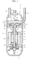
- a compressor 1 in Fig. 1 is inserted into a circulation path for circulating a working fluid in an air conditioner or a heat pump type water heater, etc., and uses, for example, a CO 2 refrigerant (hereinafter called "refrigerant") as the working fluid.
- the compressor 1 carries out suction of the refrigerant from a circulation path, compression of the sucked refrigerant, and discharge of the compressed refrigerant to the circulation path, thereby letting the refrigerant circulate in the circulation path.
- the compressor 1 has a housing 2.
- the housing 2 includes a cylindrical body portion 4 extending in the up and down direction, and an upper lid 6 and a lower lid 8 which respectively closes the upper end and lower end of the body portion 4 airtightly, defining an airtight chamber inside.
- the lower portion of the housing 2 is formed as an oil chamber 9 for storing a lubricant.
- An electric motor 10 is accommodated in the body portion 4, and has a hollow drive shaft 12 at the center thereof. When power is supplied to the motor 10, the drive shaft 12 is rotated in one direction.
- the upper end portion of the drive shaft 12 is rotatably supported by an upper frame 14 via a bearing 16, and the upper frame 14 is fixed to the body portion 4.
- the lower end portion of the drive shaft 12 is rotatably supported by a lower frame 18 via a bearing 20, and the lower frame 18 is also fixed to the body portion 4.
- An oil pump 22 is attached to the lower end of the drive shaft 12, and is driven by the rotation of the drive shaft 12. When the oil pump 22 is driven, the oil pump 22 sucks a lubricating oil in the oil chamber 9, and discharges the sucked lubricating oil into the drive shaft 12 or an oil passage 24 defined in the drive shaft 12.
- the oil passage 24 extends in the axial direction of the drive shaft 12, so that the lubricating oil discharged into the oil passage 24 is fed through the oil passage 24 toward the upper end of the drive shaft 12, and is then supplied to each sliding portion of the motor 10 and a scroll unit to be described later from the upper end of the drive shaft 12.
- the scroll unit 30 is arranged in the body portion 4, and positioned above the motor 10.
- the scroll unit 30 carries out a series of processes from suction of the refrigerant and discharge thereof through compression thereof.
- the scroll unit 30 includes an orbital scroll 52 and a fixed scroll 32.
- the orbital scroll 52 has an end plate 54 and a spiral lap 56 formed integral with the end plate 54 and projecting toward an end plate 34 of the fixed scroll 32 from the end plate 54.
- the fixed scroll 32 has the end plate 34 and a spiral lap 36 formed integral with the end plate 34 and projecting toward the end plate 54 of the orbital scroll 52.
- the spiral laps 34, 56 have spiral shapes to engage with each other, and the spiral shapes are defined substantially by the involution.
- the spiral laps 36, 56 cooperate to form a plurality of compression chambers. More specifically, a compression chamber is formed at the outer peripheries of the spiral laps 36, 56 by the revolution movement of the orbital scroll 52, and the volumes of the formed compression chamber decreases as it moves toward the centers of the spiral laps 36, 56.
- a boss 66 is formed at the bottom side of the end plate 54.
- the boss 66 is rotatably supported by an eccentric shaft 26 via a bearing 28, the eccentric shaft 26 projecting integrally from the upper end of the drive shaft 12.
- the rotation of the orbital scroll 52 is inhibited by a plurality of pins 68 which protrude toward the upper frame 14 from the end plate 54 and are positioned in holes of the upper frame 14.
- the orbital radius of the pins 68 is determined by the holes.
- the fixed scroll 32 is fixed to the upper frame 14, and a discharge chamber 80 is defined in the housing 2 between the end plate 34 of fixed scroll 32 and the upper lid 6.
- the end plate 34 has a single discharge hole 50 which is positioned slightly eccentric from the center of the end plate 34, and penetrates the end plate 34.
- a discharge valve 82 is attached to the end plate 34, and opens and closes a discharge hole 82.
- a suction pipe 84 is connected to the body portion 4 to guide the refrigerant into the body portion 4.
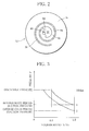
- the ratio of the volume V to the suction volume Vc or the volume ratio V/Vc is set to 0.5 or greater.
- This setting of the volume ratio V/Vc is optimal when a compressor for a heat pump type water heater, which is recently commercialized, is used to compress a CO 2 refrigerant.
- the scroll unit 30 of the embodiment has a volume ratio setting portion at the inner peripheral end of the spiral lap 36 to discharge the compressed refrigerant from the scroll unit 30 at the crank angle which determines the volume ratio V/Vc to 0.5 or greater, the position of the inner peripheral end of the spiral lap 56, i.e., the involute starting position of the spiral lap 56 is determined.
- the volume ratio setting portion of the spiral lap 36 is formed as a space filling potion 38 which increases the volume of the inner peripheral end of the spiral lap 36, and the space filling portion 38 fills the space at approximately the center portion of the end plate 34.
- the space filling portion 38 like the spiral lap 36, projects toward the orbital scroll 52 from the end plate 34.
- the outer shape of the space filling portion 38 is made by an inner wall 40 facing the discharge hole 50 side and an outer wall 42 with an arc shape projecting outward in the radial direction of the spiral lap 36.
- the inner wall 40 extends toward the discharge hole 50 from the inner peripheral surface of the spiral lap 36, then surrounds about a half of the opening edge of the discharge hole 50 (right-hand side of the opening edge of the discharge hole 50 in Fig. 2 ), and then extends toward the outer wall 42 from the discharge hole 50 to be connected to the terminal end of the outer wall 42.
- the inner peripheral end of the spiral lap 56 is formed as a retreat end 58 retreating in the spiral direction of the spiral lap 56 to avoid interference with the space filling portion 38.
- the retreat end 58 turns to come close and away from the inner wall 40 of the space filling portion 38 positioned above the discharge hole 50 shown in Fig. 4 .
- the spiral lap 56 and the space filling portion 38 of the spiral lap 36 cooperate to form a final compression chamber 74 which achieves the compression ratio of the refrigerant corresponding to the volume ratio V/Vc.
- the orbital scroll 52 when the drive shaft 12 is driven, the orbital scroll 52 makes an orbital movement with respect to the fixed scroll 32 without rotating.
- Such an orbital movement of the orbital scroll 52 allows the refrigerant in the body portion 4 to be sucked into the scroll unit 30 from the outer surface of the scroll unit 30, after which the scroll unit 30 initiates the compression process of the sucked refrigerant.
- the retreat end 58 of the spiral lap 56 contacts the inner wall 40 of the space filling portion 38, forming two compression chambers 70, 72 sandwiching the spiral lap 56. More specifically, the compression chamber 70 is positioned outside the spiral lap 56, while the compression chamber 72 is positioned inside the spiral lap 56. Those compression chambers 70, 72 are completely separated by the retreat end 58 of the spiral lap 56. With regard to the volumes of the compression chambers 70, 72, their volume ratios V/Vc both exceed 0.5.
- the compression chambers 70, 72 appears respectively at two refrigerant intake positions spaced apart from each other in the diametric direction of the scroll unit 30, and are moved to positions at the crank angle of 0°.
- the volume of the compression chamber 74 is reduced.
- the volume of the compression chamber 74 is reduced to a range of 0.5 times the suction volume Vc or less (see Fig. 3 ).
- the discharge valve 82 is opened.
- the compressed refrigerant in the compression chamber 74 is discharged into the discharge chamber 80 via the discharge valve 82.
- the discharge pressure of the refrigerant equivalent to the compression ratio of about 2.0 or greater is generated.
- the compressed refrigerant discharged into the discharge chamber 80 circulates in the housing 2, and is then fed out through a discharge pipe 86.
- the discharge pipe 86 is attached to the upper lid 6 to be connected to the discharge chamber 80. That is, in case of the embodiment, the discharge chamber 80 is not defined in the housing 2, and communicates with the inside of the body portion 4 accommodating the motor 10.
- the volume ratios of the volumes of the compression chambers 70, 72 immediately before the single compression chamber 74 is finally formed from the two compression chambers 70, 72 are set to 0.5 or greater. Therefore, even when the scroll unit 30 is operated in either the summer season where the compression efficiency of the refrigerant becomes lower or the winter season where the compression efficiency of the refrigerant is high due to a change in the density of the refrigerant, the discharge pressure of the refrigerant from the discharge hole of the scroll unit does not rise excessively, preventing excessive compression of the refrigerant.
- the scroll unit 30 needs only the single discharge hole 50, it is unnecessary to apply the technique of the Patent Document 1 to the scroll unit 30.
- the structure of the scroll unit 30 becomes simpler, the operational reliability thereof can be kept high, and further, the manufacturing cost of the scroll unit 30 becomes lower.
- the elimination of the need for communicating holes can make the discharge hole 50 larger.
- the increased diameter of the discharge hole 50 reduces the pressure loss in the discharge hole 50, which significantly contributes to reduction of the power needed by the scroll unit 30.
- the condition of determining the volume ratio V/Vc to 0.5 or greater is achieved merely by forming the space filling portion 38 at the inner peripheral end of the spiral lap 36 of the fixed scroll 32 and forming the retreat end 58 at the inner peripheral end of the spiral lap 56 of the orbital scroll 52. Therefore, excessive compression of the refrigerant is prevented merely by modifying the profiles of the existing spiral laps 36, 56. As a result, reduction in the manufacturing cost of the scroll unit 30 can be achieved surely while maintaining the performance of the unit 30.
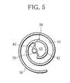
- the space filling portion 38 is not limited to be solid, but may have a cavity 43 at the center as shown in Fig. 5 . In this case, the weight of the fixed scroll 32 can be reduced.
- the starting angles of the spiral laps 36, 56 can be delayed by about 10° to about 45° in terms of the crank angle.
- forming the inner peripheral ends of the spiral laps 36, 56 as retreat ends can achieve the aforementioned condition of the volume ratio V/Vc.
- the present invention is applicable to an asymmetrical type of scroll unit which forms compression chambers 70, 72 with different shapes as well as a symmetrical type of scroll unit which forms compression chambers 70, 72 with similar shapes.
Landscapes
- Engineering & Computer Science (AREA)
- Mechanical Engineering (AREA)
- General Engineering & Computer Science (AREA)
- Rotary Pumps (AREA)
- Applications Or Details Of Rotary Compressors (AREA)
Applications Claiming Priority (2)
| Application Number | Priority Date | Filing Date | Title |
|---|---|---|---|
| JP2006189137A JP2008014288A (ja) | 2006-07-10 | 2006-07-10 | スクロール圧縮機 |
| PCT/JP2007/063493 WO2008007612A1 (fr) | 2006-07-10 | 2007-07-05 | compresseur à spirales |
Publications (1)
| Publication Number | Publication Date |
|---|---|
| EP2039936A1 true EP2039936A1 (en) | 2009-03-25 |
Family
ID=38923173
Family Applications (1)
| Application Number | Title | Priority Date | Filing Date |
|---|---|---|---|
| EP07768242A Withdrawn EP2039936A1 (en) | 2006-07-10 | 2007-07-05 | Scroll compressor |
Country Status (3)
| Country | Link |
|---|---|
| EP (1) | EP2039936A1 (ja) |
| JP (1) | JP2008014288A (ja) |
| WO (1) | WO2008007612A1 (ja) |
Cited By (1)
| Publication number | Priority date | Publication date | Assignee | Title |
|---|---|---|---|---|
| EP3816447A1 (en) * | 2019-11-04 | 2021-05-05 | Lennox Industries Inc. | Compressor for high efficiency heat pump system |
Families Citing this family (2)
| Publication number | Priority date | Publication date | Assignee | Title |
|---|---|---|---|---|
| JP5656691B2 (ja) * | 2011-03-04 | 2015-01-21 | 三菱電機株式会社 | 冷凍装置 |
| US11286931B2 (en) | 2019-08-27 | 2022-03-29 | Samsung Electronics Co., Ltd. | Scroll compressor having a shaft support portion including a closing portion |
Family Cites Families (5)
| Publication number | Priority date | Publication date | Assignee | Title |
|---|---|---|---|---|
| JPH0730682B2 (ja) * | 1990-03-23 | 1995-04-10 | 岩田塗装機工業株式会社 | スクロール式流体機械 |
| JP4192314B2 (ja) * | 1998-10-23 | 2008-12-10 | 株式会社デンソー | 超臨界冷凍サイクル |
| JP2001107881A (ja) * | 1999-10-06 | 2001-04-17 | Daikin Ind Ltd | 流体機械 |
| JP2002221169A (ja) * | 2001-01-25 | 2002-08-09 | Nippon Soken Inc | スクロール圧縮機 |
| JP2006009640A (ja) * | 2004-06-24 | 2006-01-12 | Matsushita Electric Ind Co Ltd | スクロール圧縮機 |
-
2006
- 2006-07-10 JP JP2006189137A patent/JP2008014288A/ja active Pending
-
2007
- 2007-07-05 WO PCT/JP2007/063493 patent/WO2008007612A1/ja active Application Filing
- 2007-07-05 EP EP07768242A patent/EP2039936A1/en not_active Withdrawn
Non-Patent Citations (1)
| Title |
|---|
| See references of WO2008007612A1 * |
Cited By (3)
| Publication number | Priority date | Publication date | Assignee | Title |
|---|---|---|---|---|
| EP3816447A1 (en) * | 2019-11-04 | 2021-05-05 | Lennox Industries Inc. | Compressor for high efficiency heat pump system |
| US11255325B2 (en) | 2019-11-04 | 2022-02-22 | Lennox Industries Inc. | Compressor for high efficiency heat pump system |
| US11499554B2 (en) | 2019-11-04 | 2022-11-15 | Lennox Industries Inc. | Compressor for high efficiency heat pump system |
Also Published As
| Publication number | Publication date |
|---|---|
| JP2008014288A (ja) | 2008-01-24 |
| WO2008007612A1 (fr) | 2008-01-17 |
Similar Documents
| Publication | Publication Date | Title |
|---|---|---|
| US7563080B2 (en) | Rotary compressor | |
| US8998596B2 (en) | Scroll compressor | |
| US9243636B2 (en) | Scroll compressor with differential pressure hole and communication hole | |
| US7462021B2 (en) | Rotary compressor, and car air conditioner and heat pump type water heater using the compressor | |
| US7335004B2 (en) | Apparatus for varying capacity in scroll compressor | |
| JP2008286095A (ja) | スクロール圧縮機 | |
| EP2581605A2 (en) | Scroll compressor with bypass hole | |
| EP2187060B1 (en) | Hermetic compressor and refrigeration cycle device having the same | |
| KR100715772B1 (ko) | 선회베인 압축기의 용량 가변장치 | |
| US7588428B2 (en) | Rotary fluid device performing compression and expansion of fluid within a common cylinder | |
| JP2010090859A (ja) | スクロール型流体機械 | |
| EP2039936A1 (en) | Scroll compressor | |
| EP3339647A1 (en) | Compressor | |
| JP3274900B2 (ja) | 圧縮機における給油ポンプ装置 | |
| JP6635095B2 (ja) | 回転式圧縮機 | |
| JP2009127517A (ja) | 密閉型圧縮機 | |
| JP4973148B2 (ja) | 回転式圧縮機 | |
| KR100635821B1 (ko) | 인버터 압축기의 급유량 제어장치 | |
| US20120009079A1 (en) | Single screw compressor | |
| WO2017115559A1 (ja) | スクロール圧縮機 | |
| JP2003184776A (ja) | 圧縮機 | |
| WO2021015115A1 (ja) | 圧縮機 | |
| JP2003184760A (ja) | 圧縮機 | |
| JP2000009065A (ja) | スクロール型圧縮機 | |
| JP2007092722A (ja) | スクロール圧縮機 |
Legal Events
| Date | Code | Title | Description |
|---|---|---|---|
| PUAI | Public reference made under article 153(3) epc to a published international application that has entered the european phase |
Free format text: ORIGINAL CODE: 0009012 |
|
| 17P | Request for examination filed |
Effective date: 20090107 |
|
| AK | Designated contracting states |
Kind code of ref document: A1 Designated state(s): AT BE BG CH CY CZ DE DK EE ES FI FR GB GR HU IE IS IT LI LT LU LV MC MT NL PL PT RO SE SI SK TR |
|
| AX | Request for extension of the european patent |
Extension state: AL BA HR MK RS |
|
| DAX | Request for extension of the european patent (deleted) | ||
| RBV | Designated contracting states (corrected) |
Designated state(s): DE FR GB |
|
| STAA | Information on the status of an ep patent application or granted ep patent |
Free format text: STATUS: THE APPLICATION IS DEEMED TO BE WITHDRAWN |
|
| 18D | Application deemed to be withdrawn |
Effective date: 20120201 |