EP2038470B1 - Klappe für ein Haushaltgerät - Google Patents
Klappe für ein Haushaltgerät Download PDFInfo
- Publication number
- EP2038470B1 EP2038470B1 EP07729924A EP07729924A EP2038470B1 EP 2038470 B1 EP2038470 B1 EP 2038470B1 EP 07729924 A EP07729924 A EP 07729924A EP 07729924 A EP07729924 A EP 07729924A EP 2038470 B1 EP2038470 B1 EP 2038470B1
- Authority
- EP
- European Patent Office
- Prior art keywords
- actuation
- door
- snap
- opening
- flap
- Prior art date
- Legal status (The legal status is an assumption and is not a legal conclusion. Google has not performed a legal analysis and makes no representation as to the accuracy of the status listed.)
- Not-in-force
Links
- 238000005406 washing Methods 0.000 claims description 34
- 230000001960 triggered effect Effects 0.000 claims description 11
- 238000010276 construction Methods 0.000 claims description 3
- 239000011521 glass Substances 0.000 description 14
- 230000002349 favourable effect Effects 0.000 description 11
- 230000008878 coupling Effects 0.000 description 6
- 238000010168 coupling process Methods 0.000 description 6
- 238000005859 coupling reaction Methods 0.000 description 6
- 238000007789 sealing Methods 0.000 description 5
- 125000006850 spacer group Chemical group 0.000 description 4
- 238000011161 development Methods 0.000 description 3
- 230000018109 developmental process Effects 0.000 description 3
- 238000004519 manufacturing process Methods 0.000 description 3
- 241000239290 Araneae Species 0.000 description 1
- 230000006978 adaptation Effects 0.000 description 1
- 230000001771 impaired effect Effects 0.000 description 1
- 238000002347 injection Methods 0.000 description 1
- 239000007924 injection Substances 0.000 description 1
- 230000002093 peripheral effect Effects 0.000 description 1
- XLYOFNOQVPJJNP-UHFFFAOYSA-N water Substances O XLYOFNOQVPJJNP-UHFFFAOYSA-N 0.000 description 1
Images


Classifications
-
- D—TEXTILES; PAPER
- D06—TREATMENT OF TEXTILES OR THE LIKE; LAUNDERING; FLEXIBLE MATERIALS NOT OTHERWISE PROVIDED FOR
- D06F—LAUNDERING, DRYING, IRONING, PRESSING OR FOLDING TEXTILE ARTICLES
- D06F39/00—Details of washing machines not specific to a single type of machines covered by groups D06F9/00 - D06F27/00
- D06F39/12—Casings; Tubs
- D06F39/14—Doors or covers; Securing means therefor
-
- E—FIXED CONSTRUCTIONS
- E05—LOCKS; KEYS; WINDOW OR DOOR FITTINGS; SAFES
- E05B—LOCKS; ACCESSORIES THEREFOR; HANDCUFFS
- E05B5/00—Handles completely let into the surface of the wing
- E05B5/003—Pop-out handles, e.g. sliding outwardly before rotation
Definitions
- the invention relates to a flap for a household appliance, in particular for a washing machine, comprising a movable opening element and a Schnäppervoriques comprising a movable Schnäpperbolzen and which is mechanically coupled to the opening element such that by operating the opening element in at least one actuation of the Schnäpperbolzen is movable ,
- the invention also relates to a laundry care device having such a flap.
- the assembly includes a latch pin and a handle member as an opening member rotatably disposed about a common axis fixed within the frame or flap.
- the latch bolt has a hook-like shape and is held by a spring against a stop in a rest position. In the rest position the catch bolt holds the closed window locked.
- the grip element By an actuation of the grip element, the grip element causes a movement of the Schnäpperbolzens out of its rest position, whereby the locking of the window is released and the window can be opened.
- the assembly is designed only for a possible type of actuation of the handle member, that is, the movement of the Schnäpperbolzens is only effected when the directed to the window center handle member is pulled forward or the handle member is rotated counterclockwise about its axis.
- Known front-loading washing machines have an assembly according to DE 38 09 998 A1 on, in which the latch bolt is arranged on a horizontal center line of a window opening of the washing machine and symmetrically to a vertical hinge axis of the window.
- the window can be uniformly pressed against a seal arranged between the window and the washing machine housing.
- the freedom of design of a window with such an assembly is significantly limited with respect to the handle assembly on the window, especially with regard to an ergonomic arrangement.
- a washing machine which has an opening element in the form of a handle element for actuating a Schnäppersches.
- a handle element for actuating a Schnäppersches.
- the grip element is arranged on a substantially annular window or window frame.
- the window or the flap is movably attached to the washing machine by means of a hinge device.
- the handle member is arranged asymmetrically to these hinge devices, whereby an ergonomically favorable opening operation is provided.
- the grip element is arranged substantially in a two-o'clock position on the annular window frame.
- the handle member may be actuated in a direction to actuate the latch lock, and the Schnappervoriques is formed only for the one type of actuation of the handle member.
- the Schnappervoriques is formed only for the one type of actuation of the handle member.
- only a very limited operation with regard to opening and / or closing of such a window of a washing machine is possible.
- the EP 728 861 A1 disclosed window construction is not suitable to provide the window with a handle member having a different from the handle element actuation. Therefore, for each design or equipment variant of the washing machine, which require a different type of actuation of the grip element, each a separate window variant must be created because different types of components of the Schnäppervortechnik must be provided for each variant.
- fewer identical parts can be used, whereby the creation of such design variants is costly.
- WO 2008/000595 A1 discloses a flap for a household appliance, in which a handle element is present, which points inwards, ie to the sight glass. This arrangement is common, but means that the movement to open ergonomically is not favorable.
- the actuation of the opening element for a user should be possible ergonomically favorable, without affecting the functionality of the flap is impaired, in particular, a sealing seat of the flap is to ensure a reliable to be closed with the same opening of the household appliance.
- a flap for a household appliance in particular a laundry care device, comprising an opening element and a Schnäppervoriques comprising a movable Schnäpperbolzen and which is mechanically coupled to the opening element such that by operating the opening element in at least one actuation of the latch bolt is movable
- the Schnäppervorraum is designed for a plurality of types of actuation and regardless of the type of actuation of the opening element of the Schnäpbolbolzen in only one direction is movable
- the Schnäpperbolzen are associated with a plurality of triggering elements, which are triggered for moving the Schnäpperbolzens by operating the opening element separately, depending on an actuation of the opening element in each case one of the triggering elements can be triggered.
- the invention is characterized in that the opening element is designed as a gripping element which, viewed from the middle of the flap, faces outward.
- the opening element is a grip element which is designed for a plurality of types of actuation, in particular for a first and for a second actuation type.
- an essential idea of the invention is that the Schnäppervortechnische formed for a plurality of types of actuation of the flap covered opening element and the Schnäppervorides is coupled to the opening element such that by operating the opening element in at least one actuation a Schnäppervortechnisch encompassed by the Schnäppervor Vietnamese movable regardless of the type of actuation of the opening element of the latch bolt is similar movable, that is, the latch bolt can only be moved in one direction. By the movement of the Schnäpperbolzens a lock of the flap is released, so that the flap can be opened.
- the Schnäpbolbolzen components of the domestic appliance, in particular the flap even for different flaps run the same and be placed on the household appliance. For example, only one closure device is required, which cooperates with the latch pin to hold and lock the flap to provide domestic appliance variants with a flap that differ in the manner of actuation of the flap opening element.
- an opening element can be arranged in different positions on the flap, which in addition it is easily possible to arrange the opening element at an ergonomically favorable for the user location.
- the Schnäpperbolzen several, in particular two, triggering elements assigned, which are separately triggered for moving the Schnäpperbolzens by pressing the opening element.
- one of the triggering elements can be triggered in each case.
- the Schnäppervoriques can thus be easily formed for multiple types of actuation, since for each type of actuation, the special trigger element and its coupling to the opening element can be adjusted individually.
- the Schnäppervorutter comprises a Schnäpperani on which the Schnäpperbolzen and the triggering elements are arranged, wherein the triggering elements are preferably formed as separate elements.
- a one-piece design of such a Schnäpper umans is particularly cheap and inexpensive, since it can be performed for example as an injection molded part.
- the opening element is arranged on the flap handle element, which allows only a single actuation for triggering one of the triggering elements or for moving the Schnäpperbolzens.
- the handle element required for this embodiment is simple and inexpensive representable, since it must be designed for one actuation only. It can be provided that the first triggering element can be triggered by a first actuation of the grip element for actuating the Schnäpperbolzens and the second triggering element can be triggered by a second actuation of another handle element for actuating the Schnäpperbolzens.
- the grip element arranged on the flap can be arbitrarily selected from a group of grip elements which comprises at least handle elements of the first actuation type and grip elements of the second actuation type.
- the mechanics of Schnäppervoriques thus ensures a high level of reliability with regard to the plurality of types of actuation possible handle elements.
- Design variants of the flap can therefore be formed by simply selecting a handle element which is preferred for the variant, as a result of which a multiplicity of different design variants of the flap are simply made possible.
- the opening element is a grip element which is designed for at least two different types of actuation, in particular for a first and for a second actuation type.
- different triggering elements can advantageously be triggered upon actuation of the one gripping element depending on the type of actuation.
- the Schnäppervorsch invention is thus operable in a variety of ways and triggered in a variable manner.
- the design of the Schnäppervoriques thereby allows a flexible operation. Therefore, the opening of the flap for a user can be made even more ergonomic, since the user can be advantageously provided several actuation options for opening the flap.
- the types of actuation of the gripping element or of the gripping elements are actuations in opposite directions.
- the at least two types of actuation are particularly favorably characterized in that one type of actuation essentially represents a rotational movement in a first direction about a handle axis.
- the second type of actuation is essentially a rotational movement in a second direction about the handle axis, wherein the second rotational movement may be formed opposite to the first rotational movement.
- the gripping element is arranged on the flap in such a way that the rotation of the gripping element about the gripping axis is generated, as it were, by a movement of the gripping element away from the center of the flap.
- This movement can be generated in accordance with the second type of actuation by a directed towards the center of the flap towards the movement of the handle member, whereby the rotational movement is generated around the handle axis in the opposite direction.
- the Schnäppervoriques can be actuated by simple operation of the handle member in a variable manner or the Schnäpbolbolzen be moved.
- the opening element is arranged on a handle element opening button with an actuation for triggering one of the triggering elements or for moving the Schnäpperbolzens. It can do that Handle element be both mobile as well as fixed. In particular, for moving a large and / or heavy flap, a gripping element fixed to the flap with the included opening button has proved favorable, which can absorb the forces required to move the flap well.
- the handle member may be formed in alternative embodiments by a frame of the flap or by a suitable for engaging behind flap area.
- the opening button can advantageously be formed on an ergonomically favorable for a user operating position on the handle element.
- the flap comprises according to a further advantageous embodiment, a hinge device which is rotatable about a substantially vertical hinge axis and with which the flap can be coupled to the household appliance.
- the latch bolt is arranged with the flap closed on a substantially horizontal center line of the flap to be closed by the opening of the household appliance.
- the Schnäpbolbolzen the Schnäppervorides and the opening element may be arranged substantially spatially separated from each other on the flap, thereby advantageously an ergonomically favorable for the actuation arrangement of the opening element of a tightly closing flap, in particular an arrangement of the opening element at a substantially above a center line the flap location is enabled.
- the position of the opening element is related to the horizontal center line of the flap, meaning the horizontal axis of symmetry of the flap part corresponding to the opening to be closed.
- the position of the latch bolt is related to the horizontal center line of the opening, since the outer contour of the flap can be offset from the opening to be closed for ergonomic or functional reasons.
- the latch bolt is rotatably mounted about a Schnäpperachse, which is arranged substantially parallel to the hinge axis, that is, that the Schnäpperachse has a substantially vertical orientation.
- the latch bolt when opening or closing the flap is inserted into a locking device of the household appliance cooperating with the catch bolt or executed therefrom without the latch bolt gripping or tilting on the locking device.
- the opening element is a grip element which can be rotated about a handle axis, the axis of rotation of which has a position on the flap deviating from the position of the catch axis.
- the Schnapperbolzen covered by the Schnäppervoriques can be arranged at the optimum for the tumbler or sealing seat of the flap position, even if the grip member is disposed at an ergonomic position above the horizontal center line of the opening. The Schnäpbolbolzen can thus be clearly spaced away from the handle element attached to the flap.
- the divergent position of the handle and Schnäpperachse is particularly advantageous for a flap having a held by a window ring window and in which the axes of the handle member and the Schnäpperbolzens are disposed on the window ring, since the handle member despite a spatial through the window ring predetermined restriction is very variable positioned on the window ring.
- the handle axis of the gripping element is preferably arranged at an angle ⁇ to a Schnäpperachse the Schnäppervorraum.
- the angle between the handle axis and the Schnäpperachse is about 75 °.
- the angle ⁇ is in the range of about 65 ° to 85 °, in particular in the range between 70 ° and 80 °.
- the Schnäpperachse is oriented substantially vertically. With such an arrangement of the axes, the gripping element can be arranged in an ergonomically favorable position.
- the grip element is advantageously arranged on a frame element of the flap.
- the Schnäppervoriques itself is preferably arranged on a support element of the flap.
- the support member and the handle member are preferably mechanically fixed together. It may further be provided that the flap is substantially annular and the support member is a so-called flap ring.
- the Schnappervoriques is preferably arranged opposite to the hinge device.
- the catch device and the hinge device are thus positioned substantially symmetrically to a vertical axis of symmetry of the flap part corresponding to the opening to be closed.
- the opening element and / or the grip element are preferably arranged asymmetrically to the hinge device. The asymmetry is given in relation to a vertical and / or horizontal symmetry line of the opening.
- the household appliance on which a flap according to the invention or one of the developments of this flap is arranged, is designed in particular as a domestic appliance for the care of laundry items or as a laundry care appliance.
- the laundry care device is preferably designed as a tumble dryer or a washing machine, wherein the flap for closing a feed opening of a laundry treatment room, in particular a laundry drum, is used.
- Laundry care appliances with a flap according to the invention are ergonomically favorable for a user to operate and at the same time have a flap with an optimum sealing seat on an opening of the laundry care appliance to be closed.
- the user need not to stoop to open a vertically arranged laundry flaps of a laundry care device, for example, in a so-called front loader, since the opening element and / or the handle element can be arranged correspondingly far above on such a flap.
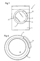
- Fig. 1 is a schematic representation of a perspective view of a household appliance for the care of laundry items shown.
- the household appliance is a washing machine 1.
- the washing machine 1 has on its front side 11 a charging opening, which can be closed by a flap 2.
- the flap 2 is designed as a loading door.
- the flap 2 is formed substantially annular and has an outer frame member 21 and a sight glass 22.
- the sight glass 22 is the corresponding to the opening to be closed flap portion which cooperates with a disposed between the opening and the sight glass 22 seal for sealing the opening.
- a handle element 23 according to the prior art as an opening element on the outer frame member 21 is arranged movable.
- the flap 2 is movably mounted on the washing machine 1 with a hinge device 24.
- the flap 2 can be pivoted about this hinge device 24, wherein a hinge axis 241 extends vertically in the embodiment.
- the prior art handle member 23 is an opening member and substantially asymmetrical to the hinge mechanism 24 in FIG With respect to a vertical and / or a horizontal axis of symmetry of the sight glass 22 is positioned.
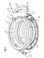
- Fig. 2 is an exploded perspective view of a flap 3 according to the invention, which also in FIG. 6 is shown.
- the flap 3 in this case comprises the outer frame element 21, on which the arc segment-like shaped handle element 33 is arranged to be movable.
- the gripping element 33 is rotatably movably arranged around a gripping axis shown on the gripping element 33.
- the flap 3 comprises the sight glass 22 and a spacer ring 25 on which the hinge device 24 is arranged. As can be seen, the spacer ring 25 is positioned between the outer frame member 21 and the sight glass 22.
- the flap 3 also has a flap ring 26, wherein the sight glass 22 is arranged in the peripheral edge region between the spacer ring 25 and the flap ring 26.
- a Schnäppervorraum 27 is arranged on the flap ring 26, .
- the catch device 27 is positioned substantially opposite the hinge device 24 and has a catch axis 271 extending substantially parallel to the hinge axis 241.
- the Schnäppervoriques 27 includes a Schnäpperani 272, on which a Schnäpperbolzen 272 a is arranged.
- the Schnäpbolbolzen 272a is hook-shaped.
- the Schnäpperany 272 is mounted in a Schnäpperhalter 273, wherein the Schnäpperhalter 273 is disposed on the flap ring 26.
- the Schnäpperhalter 273 is integrated into the flap ring 26 and preferably formed integrally with the flap ring 26.
- the flap ring 26 has an opening 261, through which the latch pin 272 a protrudes in the assembled state of the flap 2.
- the exploded view of the Fig. 2 shown partial elements of the flap 2 are stably connected together in the assembled state of the flap 2, so that the flap 2 represents a single overall system.
- the handle axis 231 is an angle ⁇ (shown in FIG Fig. 3 ) rotated relative to the Schnäpperachse 271.
- the outer frame member 21 has a recess 211 in which the handle member 33 is arranged.
- the handle member 33 is arranged movable in the embodiment in an actuation relative to the outer frame member 21.
- the type of movement is a rotary movement about the handle axis 231.
- the actuation of the grip element 33 takes place with respect to the grip element 23 Fig.1 in the opposite direction.
- the grip element 33 is pulled away on the outer edge 333 of the washing machine 1, whereby a rotational movement about the handle axis 231 according to the arrow representation 332 takes place.
- a flap ring 26 of the flap 3 is shown. It is clarified here that the handle axis 231 is arranged at an angle ⁇ in comparison to the catch axis 271 arranged vertically in the exemplary embodiment.
- the catch axis 271 is substantially parallel to the vertical axis of symmetry 2a of the sight glass 22.
- the grip element 33 is positioned both asymmetrically to the vertical axis of symmetry 2a and to the horizontal axis of symmetry 2b of the sight glass 22 with respect to the hinge device 24 and / or the Schnappervorraum 27.
- the grip element 33 is arranged substantially in a two o'clock position.
- the handle axis 231 is tilted in the embodiment with respect to the horizontal axis of symmetry 2b of the sight glass 22 by an angle ⁇ of about 165 ° counterclockwise.
- the angle ⁇ between the Schnäpperachse 271 and the handle axis 231 is about 75 ° in the embodiment.
- the handle member 33 and the Schnäppervoriques 27 in in Fig. 3 shown first quarter of a segment-like division of the flap 2 arranged.
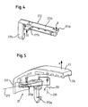
- Fig. 4 is a perspective view of the Schnäpper whatsoevers 272 of the Schnäppervorraum 27 shown.
- the spider carrier 272 in the exemplary embodiment has an elongated structure, which is formed by the main carrier 272b.
- the catch bolt 272a is fixed at a first end, which is movably arranged or mounted with the main carrier 272b via a spring coupling.
- the hook-shaped latch pin 272a is mechanically coupled to a first trigger element 272d.
- the two trigger elements 272c and 272d plate-shaped and arranged on the main carrier 272b. Furthermore, from the illustration in Fig. 4 it can be seen, the trigger elements 272c and 272d are arranged on opposite sides of the main carrier 272b. They each protrude in opposite directions from this main carrier 272b.
- the first trigger member 272c is disposed adjacent to the latch bolt 272a, whereas the second trigger member 272d is disposed at the second end of the main carrier 272b.
- the two trigger elements 272c and 272d are connected to a handle element 23 according to the prior art or with the handle element 33 according to the invention in mechanical operative connection such that depending on the type of operation of the handle member 23 and the handle member 33, either the first trigger element 272c or the second Trigger element 272d are actuated and then depending on the Schnäpperbolzen 272a is actuated.
- the in Fig. 5 shown arrangement of the trigger element 272d such that when the handle member 23 in the direction A, ie moved away from the washing machine 1 or pulled, the first trigger element 272d is actuated. In this case, a force is introduced in accordance with the direction of arrow B from above onto the first triggering element 272d.
- the mechanical coupling is thus such that the handle element 23 according to the prior art pushes the release element 272d from top to bottom, whereas in the second actuation mode the grip element 33 pulls the second release element 272c from the bottom upwards.
- FIG. 6 shows the arrangement of the handle member 33 on the flap 2, which faces outward.
- the required for the flap 3 sub-elements are the same except for the different grip elements.
- the two flap variants can be produced particularly inexpensively.
- a flap not shown, a fixed handle member 43 which protrudes from the housing of the washing machine.
- the Fig. 7 shows a section of the top view of the upper housing wall or the cover of the washing machine.
- An opening element 431 is arranged on the grip element 43, which interacts with the catch device in an actuation manner when the opening element 431 is actuated such that the catch bolt 272a is moved.
- the direction of movement of the latch bolt caused by actuation of the opening element 431 is equal to the direction of movement of the latch bolt 272a caused by actuation of the grip element 23 or 33.
- FIGS. 8 and 9 show a further embodiment in which the washing machine comprises a flap 5 with a handle member 53 having both a first and a second mode of actuation.
- the gripping element 53 protruding from the washing machine can be moved inward in a direction D as well as in a further direction E, as a result of which the gripping element 53 is moved around the gripping axis 231 in oppositely directed rotational movements.
- Such a flap can be operated even easier by an operator.
- the gripping element 53 with its two possible types of actuation is mechanically coupled to the catch device 27 in such a way that, regardless of the type of actuation of the gripping element 53, the latch bolt 272a is always actuated the same.
- This is achieved in that, in one type of actuation, a region of the grip element presses on the trigger element 272d and, in the case of the other actuation, pulls a region of the grip element on the second trigger element 272c. Since the trigger members 272d and 272c are disposed on opposite sides of the sprocket carrier 272, both types of operation of the grip member each cause rotational movement of the latch bolt 272a about the latch shaft 271 in the same rotational direction.
- the different types of actuation of the handle element thus always allow one equivalent action of the Schnäppervorraum 27 and in particular the Schnäpperbolzens 272a.
Landscapes
- Engineering & Computer Science (AREA)
- Textile Engineering (AREA)
- Main Body Construction Of Washing Machines And Laundry Dryers (AREA)
- Wing Frames And Configurations (AREA)
- Vending Machines For Individual Products (AREA)
- Liquid Crystal (AREA)
Description
- Die Erfindung betrifft eine Klappe für ein Haushaltgerät, insbesondere für eine Waschmaschine, umfassend ein bewegliches Öffnungselement und eine Schnäppervorrichtung, die einen beweglichen Schnäpperbolzen umfasst und die mit dem Öffnungselement derart mechanisch koppelbar ist, dass durch Betätigen des Öffnungselements in zumindest einer Betätigungsart der Schnäpperbolzen bewegbar ist. Die Erfindung betrifft auch ein Wäschepflegegerät mit einer solchen Klappe.
- Aus der deutschen Offenlegungsschrift
DE 38 09 998 A1 ist eine Baugruppe für ein Fenster oder eine Klappe einer Haushaltswaschmaschine bekannt. Die Baugruppe weist einen Schnäpperbolzen und ein Griffelement als ein Öffnungselement auf, die um eine gemeinsame im Rahmen des Fensters oder der Klappe befestigten Achse drehbeweglich angeordnet sind. Der Schnäpperbolzen hat eine hakenförmige Gestalt und wird mittels einer Feder gegen einen Anschlag in einer Ruheposition gehalten. In der Ruheposition hält der Schnäpperbolzen das geschlossene Fenster verriegelt. Durch eine Betätigung des Griffelements bewirkt das Griffelement eine Bewegung des Schnäpperbolzens aus seiner Ruheposition heraus, wodurch die Verriegelung des Fensters freigegeben wird und das Fenster geöffnet werden kann. Die Baugruppe ist nur für eine mögliche Betätigungsart des Griffelements ausgelegt, das heißt, dass die Bewegung des Schnäpperbolzens nur dann bewirkt wird, wenn das zur Fenstermitte gerichtete Griffelement nach vorn gezogen wird bzw. das Griffelement gegen Uhrzeigersinn um seine Achse gedreht wird. - Bekannte Waschmaschinen der Frontladerbauart weisen eine Baugruppe gemäß
DE 38 09 998 A1 auf, bei denen der Schnäpperbolzen auf einer horizontalen Mittellinie einer Fensteröffnung der Waschmaschine und symmetrisch zu einer vertikalen Scharnierachse des Fensters angeordnet ist. Durch eine solche symmetrische Anordnung kann das Fenster gleichmäßig an eine zwischen dem Fenster und dem Waschmaschinengehäuse angeordnete Dichtung gepresst werden. Die Gestaltungsfreiheit eines Fensters mit einer solchen Baugruppe ist in Bezug auf die Griffanordnung am Fenster deutlich eingeschränkt, insbesondere im Hinblick auf eine ergonomisch günstige Anordnung. - Darüber hinaus ist aus
EP 728 861 A1 - Das Griffelement kann in eine Richtung betätigt werden, um das Schnäpperschloss zu betätigen, und die Schnäppervorrichtung ist lediglich für die eine Betätigungsart des Griffelements ausgebildet. Somit ist nur eine sehr eingeschränkte Betätigung im Hinblick auf ein Öffnen und/oder Schließen eines derartigen Fensters einer Waschmaschine möglich. Die in
EP 728 861 A1 - Darüber hinaus ist bei der in
EP 728 861 A1 - In der
WO 2008/000595 A1 ist eine Klappe für ein Haushaltsgerät offenbart, bei der ein Griffelement vorhanden ist, welches nach innen, also zum Schauglas hin, zeigt. Diese Anordnung ist üblich, bedeutet aber, dass die Bewegung zum Öffnen ergonomisch nicht günstig ist. - Daher ist es Aufgabe der vorliegenden Erfindung, eine Klappe für ein Haushaltgerät, insbesondere ein Wäschepflegegerät, zu schaffen, die hinsichtlich der Betätigungsart eines an der Klappe angeordneten Öffnungselements vielfältig gestaltet werden kann. In einem weiteren Aspekt der Erfindung soll das Betätigen des Öffnungselements für einen Benutzer ergonomisch günstig möglich sein, ohne dass dadurch die Funktionsfähigkeit der Klappe beeinträchtigt ist, insbesondere ist dabei ein Dichtsitz der Klappe an einer mit derselben zu verschließenden Öffnung des Haushaltgeräts zuverlässig zu gewährleisten.
- Diese Aufgabe wird durch eine Klappe für ein Haushaltgerät, insbesondere ein Wäschepflegegerät, umfassend ein Öffnungselement und eine Schnäppervorrichtung, die einen beweglichen Schnäpperbolzen umfasst und die mit dem Öffnungselement derart mechanisch koppelbar ist, dass durch Betätigen des Öffnungselements in zumindest einer Betätigungsart der Schnäpperbolzen bewegbar ist, wobei die Schnäppervorrichtung für mehrere Betätigungsarten ausgebildet ist und unabhängig von der Betätigungsart des Öffnungselements der Schnäpperbolzen in nur einer Richtung bewegbar ist, wobei dem Schnäpperbolzen mehrere Auslöseelemente zugeordnet sind, die zum Bewegen des Schnäpperbolzens durch Betätigen des Öffnungselements separat auslösbar sind, wobei abhängig von einer Betätigungsart des Öffnungselements jeweils eines der Auslöseelemente auslösbar ist. Die Erfindung ist dadurch gekennzeichnet, dass das Öffnungselement als ein Griffelement ausgestaltet ist, das von der Klappenmitte gesehen nach außen zeigt.
- Vorteilhafte Ausgestaltungen der Erfindung sind in den Unteransprüchen aufgeführt. So ist z.B. auch eine Ausführungsform vorgesehen, bei der das Öffnungselement ein Griffelement ist, das für mehrere Betätigungsarten, insbesondere für eine erste und für eine zweite Betätigungsart, ausgebildet ist.
- Ein wesentlicher Gedanke der Erfindung besteht darin, dass die Schnäppervorrichtung für mehrere Betätigungsarten eines von der Klappe umfassten Öffnungselements ausgebildet und die Schnäppervorrichtung derart mit dem Öffnungselement koppelbar ist, dass durch Betätigen des Öffnungselements in zumindest einer Betätigungsart ein von der Schnäppervorrichtung umfasster Schnäpperbolzen bewegbar ist, wobei unabhängig von der Betätigungsart des Öffnungselements der Schnäpperbolzen gleichartig bewegbar ist, das heißt, dass der Schnäpperbolzen nur in einer Richtung bewegt werden kann. Durch die Bewegung des Schnäpperbolzens wird eine Verriegelung der Klappe freigegeben, so dass die Klappe geöffnet werden kann. Vorteilhafterweise können somit die mit dem Schnäpperbolzen zusammenwirkenden Bauteile des Haushaltgeräts, insbesondere der Klappe, auch für verschiedene Klappen gleich ausgeführt und am Haushaltgerät angeordnet werden. So ist beispielsweise nur eine Verschlussvorrichtung erforderlich, die mit dem Schnäpperbolzen zum Zuhalten und Verriegeln der Klappe zusammenwirkt, um Hausgerätevarianten mit einer Klappe bereitzustellen, die sich in der Betätigungsart des Öffnungselements der Klappe unterscheiden.
- Es ist auch günstig, dass mit der erfindungsgemäßen Schnäppervorrichtung unterschiedliche Offnungselemente an der Klappe verwendbar sind, die über die für die eine und/oder die andere Betätigungsart vorgesehene mechanische Kopplung auf die Schnäppervorrichtung einwirken. Dennoch ist die Schnäppervorrichtung derart konzipiert, dass die durch Betätigen des Öffnungselements hervorgerufene Betätigung der Schnäppervorrichtung stets die gleiche ist. Durch die entsprechende Wahl einer oder mehrerer Betätigungsarten des Öffnungselements kann somit immer eine Betätigung der Schnäppervorrichtung erreicht werden, welche einheitlich ist und somit unabhängig von der Betätigungsart des Öffnungselements ausgelöst werden kann. Somit kann einfach eine Baugruppe für eine Klappe mit der Schnäppervorrichtung gebildet werden, an der zur Komplettierung der Klappe wahlweise ein Öffnungselement für verschiedenartige Betätigungsarten angeordnet werden kann. Die Klappe kann durch die vielfältige Verwendung unterschiedlicher Öffnungselemente einfach an die jeweiligen Designanforderungen angepasst werden. Für die Fertigung solcher an das Design angepasster Klappen kann eine Vielzahl an Gleichteilen verwenden, wodurch die Herstellungskosten dieser Designvarianten herabgesetzt werden.
- Da die Schnäppervorrichtung für mehrere Betätigungsarten ausgelegt ist, kann ein Öffnungselement in unterschiedlichen Lagen an Klappe angeordnet werden, wodurch es darüber hinaus einfach möglich ist, das Öffnungselement an einer für den Benutzer ergonomisch günstigen Lage anzuordnen.
- Vorteilhafterweise sind in einer Ausgestaltung dem Schnäpperbolzen mehrere, insbesondere zwei, Auslöseelemente zugeordnet, die zum Bewegen des Schnäpperbolzens durch Betätigen des Öffnungselements separat auslösbar sind. Dabei ist abhängig von einer Betätigungsart jeweils eines der Auslöseelemente auslösbar. Die Schnäppervorrichtung kann somit einfach für mehrere Betätigungsarten ausgebildet werden, da für jede Betätigungsart das spezielle Auslöseelement und deren Kopplung zum Öffnungselement einzeln angepasst werden kann.
- Es hat sich als günstig erwiesen, wenn die Schnäppervorrichtung einen Schnäpperträger umfasst, an dem der Schnäpperbolzen und die Auslöseelemente angeordnet sind, wobei die Auslöseelemente bevorzugt als separate Elemente ausgebildet sind. Dabei ist eine einstückige Ausgestaltung eines solchen Schnäpperträgers besonders günstig und preiswert, da es beispielsweise als Spritzgussteil ausgeführt sein kann. Durch die Vereinzelung der Auslöseelemente kann eine einfache Anpassung an die Kopplung zum Öffnungselement ermöglicht werden.
- In einer weiteren Ausgestaltung der Klappe ist das Öffnungselement ein an der Klappe angeordnetes Griffelement, welches nur eine einzige Betätigungsart zum Auslösen eines der Auslöseelemente bzw. zum Bewegen des Schnäpperbolzens ermöglicht. Das für diese Ausgestaltung benötigte Griffelement ist einfach und preiswert darstellbar, da es nur für eine Betätigungsart ausgebildet sein muss. Es kann vorgesehen sein, dass das erste Auslöseelement durch eine erste Betätigungsart des Griffelements zum Betätigen des Schnäpperbolzens auslösbar ist und das zweite Auslöseelement durch eine zweite Betätigungsart eines weiteren Griffelements zum Betätigen des Schnäpperbolzens auslösbar ist. Daher kann das an der Klappe angeordnete Griffelement beliebig aus einer Gruppe von Griffelementen, die zumindest Griffelemente der ersten Betätigungsart und Griffelemente der zweiten Betätigungsart umfasst, ausgewählt sein. Die Mechanik der Schnäppervorrichtung gewährleistet somit eine hohe Zuverlässigkeit auch im Hinblick auf die Mehrzahl an Betätigungsarten möglicher Griffelemente. Designvarianten der Klappe können daher durch einfache Auswahl eines für die Variante bevorzugten Griffelements gebildet werden, wodurch einfach eine Vielzahl unterschiedliche Designvarianten der Klappe ermöglicht werden.
- Ein weiterer Gedanke der Erfindung besteht darin, dass das Öffnungselement ein Griffelement ist, das für zumindest zwei unterschiedliche Betätigungsarten, insbesondere für eine erste und für eine zweite Betätigungsart, ausgebildet ist. Somit sind vorteilhafterweise bei Betätigen des einen Griffelements abhängig von der Betätigungsart unterschiedliche Auslöseelemente auslösbar. Die erfindungsgemäße Schnäppervorrichtung ist somit in vielfältiger Weise bedienbar und in variabler Weise auslösbar. Die Ausgestaltung der Schnäppervorrichtung ermöglicht dadurch eine flexible Betätigung. Daher kann das Öffnen der Klappe für einen Benutzer noch ergonomischer ausgeführt werden, da dem Benutzer mehrere Betätigungsmöglichkeiten zum Öffnen der Klappe vorteilhafterweise bereitgestellt werden können.
- In vorteilhafter Weise sind die Betätigungsarten des Griffelements bzw. der Griffelemente Betätigungen in entgegengesetzte Richtungen. Die zumindest zwei Betätigungsarten sind besonders günstig dadurch charakterisiert, dass eine Betätigungsart im Wesentlichen eine Drehbewegung in eine erste Richtung um eine Griffachse darstellt. Die zweite Betätigungsart ist im Wesentlichen eine Drehbewegung in eine zweite Richtung um die Griffachse, wobei die zweite Drehbewegung entgegengesetzt der ersten Drehbewegung ausgebildet sein kann. Das Griffelement ist an der Klappe derart angeordnet, dass die Drehung des Griffelements um die Griffachse quasi durch eine Bewegung des Griffelements von der Mitte der Klappe weg nach außen erzeugt wird. Diese Bewegung kann gemäß der zweiten Betätigungsart durch eine zur Mitte der Klappe hin gerichtete Bewegung des Griffelements generiert werden, wodurch die Drehbewegung um die Griffachse in entgegengesetzter Richtung erzeugt wird. Somit kann die Schnäppervorrichtung durch einfache Betätigung des Griffelements in variabler Weise betätigt bzw. der Schnäpperbolzen bewegt werden.
- In einer weiteren vorteilhaften Ausgestaltung der Erfindung ist das Öffnungselement eine an einem Griffelement angeordnete Öffnungstaste mit einer Betätigungsart zum Auslösen eines der Auslöseelemente bzw. zum Bewegen des Schnäpperbolzens. Dabei kann das Griffelement sowohl beweglich wie auch feststehend sein. Insbesondere für das Bewegen einer großen und/oder schweren Klappe hat sich ein an der Klappe feststehendes Griffelement mit der umfassten Öffnungstaste als günstig erwiesen, der die zum Bewegen der Klappe erforderlichen Kräfte gut aufnehmen kann. Das Griffelement kann in alternativen Ausgestaltungen auch durch einen Rahmen der Klappe oder durch einen zum Hintergreifen geeigneten Klappenbereich gebildet sein. Die Öffnungstaste kann vorteilhaft an einer für einen Benutzer ergonomisch günstigen Betätigungslage an dem Griffelement ausgebildet sein.
- Die Klappe umfasst gemäß einer weiteren vorteilhaften Weiterbildung eine Scharniervorrichtung, welche um eine im Wesentlichen vertikale Scharnierachse drehbar ist und mit welcher die Klappe an dem Haushaltgerät ankoppelbar ist. Gemäß dieser Weiterbildung ist der Schnäpperbolzen bei geschlossener Klappe auf einer im Wesentlichen horizontalen Mittellinie der von der Klappe zu verschließenden Öffnung des Haushaltgeräts angeordnet. Durch eine derartige Anordnung des Schnäpperbolzens kann erreicht werden, dass eine zur Scharniervorrichtung symmetrische Abstützung der Klappe in Bezug auf die Öffnung bzw. auf eine an der Öffnung angeordnete Dichtung beibehalten werden kann, wodurch ein Dichtsitz der geschlossenen Klappe optimal gewährleistet werden kann. Bei dieser Anordnung können der Schnäpperbolzen der Schnäppervorrichtung und das Öffnungselement im Wesentlichen räumlich voneinander getrennt an der Klappe angeordnet sein, wodurch vorteilhafterweise eine für das Betätigen ergonomisch günstige Anordnung des Öffnungselements einer dicht schließenden Klappe, insbesondere eine Anordnung des Öffnungselement an einer im Wesentlichen oberhalb einer Mittellinie der Klappe gelegenen Lage, ermöglicht wird. Die Lage des Öffnungselements ist auf die horizontale Mittellinie der Klappe bezogen, gemeint ist die horizontale Symmetrieachse des zu der zu verschließenden Öffnung korrespondierenden Klappenteils. Die Lage des Schnäpperbolzen ist auf die horizontale Mittellinie der Öffnung bezogen, da die äußere Kontur der Klappe aus ergonomischen oder funktionalen Gründen gegenüber der zu verschließenden Öffnung versetzt angeordnet sein kann.
- Besonders günstig ist eine Weiterbildung, bei der der Schnäpperbolzen drehbar um eine Schnäpperachse gelagert ist, die im Wesentlichen parallel zu der Scharnierachse angeordnet ist, d.h., dass die Schnäpperachse eine im Wesentlichen vertikale Ausrichtung hat. Bei einer solchen Anordnung kann der Schnäpperbolzen beim Öffnen oder Schließen der Klappe in eine mit dem Schnäpperbolzen zusammenwirkende Zuhaltevorrichtung des Haushaltgeräts eingeführt bzw. aus derselben ausgeführt werden, ohne dass der Schnäpperbolzen dabei an der Zuhaltevorrichtung schleift oder verkantet.
- Vorteilhafterweise ist das Öffnungselement ein um eine Griffachse drehbares Griffelement, dessen Drehachse eine von der Lage der Schnäpperachse abweichende Lage an der Klappe aufweist. So kann der von der Schnäppervorrichtung umfasste Schnäpperbolzen an der für die Zuhaltung bzw. Dichtsitz der Klappe optimalen Lage angeordnet werden, auch wenn das Griffelement an einer ergonomisch günstigen Lage oberhalb der horizontalen Mittellinie der Öffnung angeordnet ist. Der Schnäpperbolzen kann somit deutlich räumlich entfernt von dem Griffelement an der Klappe befestigt sein. Darüber hinaus ist die abweichende Lage de Griff- und Schnäpperachse besonders vorteilhaft für eine Klappe, die ein von einem Fensterring gehaltenes Fenster aufweist und bei der die Achsen des Griffelements und des Schnäpperbolzens an dem Fensterring angeordnet sind, da das Griffelement trotz einer durch den Fensterring räumlich vorgegebenen Beschränkung sehr variabel am Fensterring positionierbar ist.
- Die Griffachse des Griffelements ist in bevorzugter Weise im Winkel α zu einer Schnäpperachse der Schnäppervorrichtung angeordnet. Bevorzugt ist der Winkel zwischen der Griffachse und der Schnäpperachse etwa 75°. Es kann auch vorgesehen sein, dass der Winkel α im Bereich von etwa 65° bis 85°, insbesondere im Bereich zwischen 70° und 80° liegt. Bevorzugt ist die Schnäpperachse im Wesentlichen vertikal orientiert. Bei einer solchen Anordnung der Achsen kann das Griffelement in einer ergonomisch günstigen Position angeordnet sein.
- Das Griffelement ist in vorteilhafter Weise an einem Rahmenelement der Klappe angeordnet. Die Schnäppervorrichtung selbst ist bevorzugt an einem Trägerelement der Klappe angeordnet. Das Trägerelement und das Griffelement sind bevorzugterweise mechanisch fest miteinander verbunden. Es kann weiter vorgesehen sein, dass die Klappe im Wesentlichen ringförmig ausgebildet ist und das Trägerelement einen so genannten Klappenring darstellt.
- An der Klappe ist die Schnäppervorrichtung bevorzugt gegenüberliegend zu der Scharniervorrichtung angeordnet. Die Schnäppervorrichtung und die Scharniervorrichtung sind somit im Wesentlichen symmetrisch zu einer vertikalen Symmetrieachse des zu der zu verschließenden Öffnung korrespondierenden Klappenteils positioniert. Dabei sind das Öffnungselement und/oder das Griffelement bevorzugt asymmetrisch zur Scharniervorrichtung angeordnet. Die Asymmetrie ist dabei in Bezug zu einer vertikalen und/oder horizontalen Symmetrielinie der Öffnung angegeben.
- Das Haushaltgerät, an dem eine erfindungemäße Klappe oder eine der Weiterbildungen dieser Klappe angeordnet ist, ist insbesondere als Haushaltgerät zur Pflege von Wäschestücken bzw. als ein Wäschepflegegerät ausgebildet. Das Wäschepflegegerät ist bevorzugt als ein Wäschetrockner oder eine Waschmaschine ausgebildet, wobei die Klappe zum Verschließen einer Beschickungsöffnung eines Wäschebehandlungsraums, insbesondere einer Wäschetrommel, dient. Wäschepflegegeräte mit einer erfindungsgemäßen Klappe sind für einen Benutzer ergonomisch günstig zu betätigen und weisen zugleich eine Klappe mit einem optimalen Dichtsitz an einer zu verschließenden Öffnung des Wäschepflegegeräts auf. Insbesondere braucht sich der Benutzer zum Öffnen einer senkrecht angeordneten Wäscheraumklappe eines Wäschepflegegeräts, beispielsweise bei einem so genannten Frontlader, nicht zu bücken, da das Öffnungselement und/oder das Griffelement entsprechend weit oben an einer solchen Klappe angeordnet sein kann.
- Darüber hinaus können eine Mehrzahl an unterschiedlichen Betätigungen des Öffnungs- und/oder Griffelements bei gleich bleibender Konstruktion der restlichen Bauteile realisiert werden.
- Die Erfindung wird nachfolgend anhand schematischer Zeichnungen näher erläutert. Es zeigen:
- Fig. 1
- eine schematische Darstellung einer Waschmaschine mit einem Öffnungselement gemäß Stand der Technik,
- Fig. 2
- eine Explosionsdarstellung einer Klappe der Waschmaschine gemäß
Figur 1 aber mit einem erfindungsgemäßen Öffnungselement, - Fig. 3
- ein Trägerelement einer Klappe,
- Fig. 4
- eine perspektivische Darstellung eines Teilbereichs einer Schnäppervorrichtung,
- Fig. 5
- eine Explosionsdarstellung der Schnäppervorrichtung mit einem Griffelement,
- Fig. 6
- eine Draufsicht auf die Klappe gemäß
Figur 2 , - Fig.7
- eine Ausschnittsansicht einer Waschmaschine von oben mit einem Griffelement, das ein Öffnungselement umfasst,
- Fig. 8
- eine schematische Ansicht einer Waschmaschine mit einem Griffelement mit zwei Betätigungsarten und
- Fig. 9
- eine Ausschnittsansicht der Waschmaschine gemäß Fig. 10 von oben mit einem Griffelement.
- In den Figuren werden gleiche oder funktionsgleiche Elemente mit den gleichen Bezugszeichen versehen.
- In
Fig. 1 ist in schematischer Weise eine perspektivische Darstellung eines Haushaltgeräts zur Pflege von Wäschestücken dargestellt. Im Ausführungsbeispiel ist das Haushaltgerät eine Waschmaschine 1. Die Waschmaschine 1 weist an ihrer Frontseite 11 eine Beschickungsöffnung auf, welche durch eine Klappe 2 verschließbar ist. Die Klappe 2 ist als Beschickungstüre ausgebildet. Wie aus der Darstellung inFig. 1 zu erkennen ist, ist die Klappe 2 im Wesentlichen ringförmig ausgebildet und weist ein äußeres Rahmenelement 21 und ein Schauglas 22 auf. Das Schauglas 22 ist das zu der zu verschließenden Öffnung korrespondierende Klappenteil, das mit einer zwischen der Öffnung und dem Schauglas 22 angeordneten Dichtung zum Abdichten der Öffnung zusammenwirkt. Darüber hinaus ist ein Griffelement 23 gemäß Stand der Technik als Öffnungselement an dem äußeren Rahmenelement 21 bewegbar angeordnet. Die Klappe 2 ist mit einer Scharniervorrichtung 24 an der Waschmaschine 1 bewegbar befestigt. Um diese Scharniervorrichtung 24 kann somit die Klappe 2 geschwenkt werden, wobei eine Scharnierachse 241 im Ausführungsbeispiel vertikal verläuft. Das Griffelement 23 gemäß Stand der Technik ist ein Öffnungselement und im Wesentlichen asymmetrisch zur Scharniervorrichtung 24 im Hinblick auf eine vertikale und/oder eine horizontale Symmetrieachse des Schauglases 22 positioniert. - In
Fig. 2 ist eine perspektivische Explosionsdarstellung einer erfindungsgemäßen Klappe 3 gezeigt, die auch inFigur 6 dargestellt ist. Die Klappe 3 umfasst dabei das äußere Rahmenelement 21, an dem das bogensegmentartig geformte Griffelement 33 bewegbar angeordnet ist. Das Griffelement 33 ist dabei um eine am Griffelement 33 dargestellte Griffachse drehbar beweglich angeordnet. Darüber hinaus umfasst die Klappe 3 das Schauglas 22 und einen Distanzring 25, an dem die Scharniervorrichtung 24 angeordnet ist. Wie zu erkennen ist, ist der Distanzring 25 zwischen dem äußeren Rahmenelement 21 und dem Schauglas 22 positioniert. - Darüber hinaus weist die Klappe 3 auch einen Klappenring 26 auf, wobei das Schauglas 22 im umlaufenden Randbereich zwischen dem Distanzring 25 und dem Klappenring 26 angeordnet ist. An dem Klappenring 26 ist eine Schnäppervorrichtung 27 angeordnet. Die Schnäppervorrichtung 27 ist im Wesentlichen gegenüberliegend der Scharniervorrichtung 24 positioniert und weist eine im Wesentlichen zur Scharnierachse 241 parallel verlaufende Schnäpperachse 271 auf.
- Die Schnäppervorrichtung 27 umfasst einen Schnäpperträger 272, an dem ein Schnäpperbolzen 272a angeordnet ist. Der Schnäpperbolzen 272a ist hakenförmig ausgebildet. Der Schnäpperträger 272 ist in einem Schnäpperhalter 273 gelagert, wobei der Schnäpperhalter 273 an dem Klappenring 26 angeordnet ist. In bevorzugter Weise ist der Schnäpperhalter 273 in den Klappenring 26 integriert und bevorzugt einstückig mit dem Klappenring 26 ausgebildet. Der Klappenring 26 weist eine Öffnung 261 auf, durch die der Schnäpperbolzen 272a im zusammengesetzten Zustand der Klappe 2 hindurchragt. Die in der Explosionsdarstellung der
Fig. 2 gezeigten Teilelemente der Klappe 2 sind im zusammengesetzten Zustand der Klappe 2 stabil miteinander verbunden, so dass die Klappe 2 ein einheitliches Gesamtsystem darstellt. - Wie bereits aus der Darstellung in
Fig. 2 zu erkennen ist, ist die Griffachse 231 um einen Winkel α (dargestellt inFig. 3 ) gegenüber der Schnäpperachse 271 gedreht. - Wie des Weiteren aus der Darstellung in
Fig. 2 zu erkennen ist, weist das äußere Rahmenelement 21 eine Aussparung 211 auf, in der das Griffelement 33 angeordnet ist. Das Griffelement 33 ist im Ausführungsbeispiel in einer Betätigungsart relativ zu dem äußeren Rahmenelement 21 bewegbar angeordnet. Die Bewegungsart ist dabei eine Drehbewegung um die Griffachse 231. - Die Betätigung des Griffelements 33 erfolgt gegenüber dem Griffelement 23 aus
Fig.1 in entgegengesetzter Richtung. Dabei wird das Griffelement 33 am außen liegenden Rand 333 von der Waschmaschine 1 weg gezogen, wodurch eine Drehbewegung um die Griffachse 231 gemäß der Pfeildarstellung 332 erfolgt. - In
Fig. 3 ist ein Klappenring 26 der Klappe 3 gezeigt. Hierbei ist verdeutlicht, dass die Griffachse 231 in einem Winkel α im Vergleich zur im Ausführungsbeispiel vertikal angeordneten Schnäpperachse 271 angeordnet ist. Die Schnäpperachse 271 ist im Wesentlichen parallel zur vertikalen Symmetrieachse 2a des Schauglases 22. Das Griffelement 33 ist sowohl asymmetrisch zur vertikalen Symmetrieachse 2a als auch zur horizontalen Symmetrieachse 2b des Schauglases 22 im Hinblick auf die Scharniervorrichtung 24 und/oder der Schnäppervorrichtung 27 positioniert. Im Ausführungsbeispiel ist das Griffelement 33 im Wesentlichen in einer Zwei-Uhr-Position angeordnet. Die Griffachse 231 ist im Ausführungsbeispiel gegenüber der horizontalen Symmetrieachse 2b des Schauglases 22 um einen Winkel β von etwa 165° gegen den Uhrzeigersinn geneigt. Der Winkel α zwischen der Schnäpperachse 271 und der Griffachse 231 ist im Ausführungsbeispiel etwa 75°. - Im Ausführungsbeispiel ist das Griffelement 33 und die Schnäppervorrichtung 27 im in
Fig. 3 gezeigten ersten Viertel einer segmentartigen Aufteilung der Klappe 2 angeordnet. - In
Fig. 4 ist eine perspektivische Darstellung des Schnäpperträgers 272 der Schnäppervorrichtung 27 gezeigt. Der Schnäpperträger 272 weist im Ausführungsbeispiel eine längliche Struktur auf, welche durch den Hauptträger 272b gebildet wird. An diesem Hauptträger 272b ist an einem ersten Ende der Schnäpperbolzen 272a befestigt, der mit dem Hauptträger 272b über eine Federkopplung bewegbar angeordnet bzw. gelagert. Der hakenförmige Schnäpperbolzen 272a ist mit einem ersten Auslöseelement 272d mechanisch gekoppelt. - Wie aus der Darstellung in
Fig. 4 zu erkennen ist, sind die beiden Auslöseelemente 272c und 272d plattenförmig ausgebildet und an dem Hauptträger 272b angeordnet. Wie darüber hinaus des Weiteren aus der Darstellung inFig. 4 zu erkennen ist, sind die Auslöseelemente 272c und 272d an gegenüberliegenden Seiten des Hauptträgers 272b angeordnet. Sie ragen jeweils in entgegengesetzter Richtung von diesem Hauptträger 272b weg. Das erste Auslöseelement 272c ist benachbart zum Schnäpperbolzen 272a angeordnet, wohingegen das zweite Auslöseelement 272d an dem zweiten Ende des Hauptträgers 272b angeordnet ist. - Die beiden Auslöseelemente 272c und 272d sind mit einem Griffelement 23 gemäß Stand der Technik bzw. mit dem Griffelement 33 gemäß der Erfidnung in mechanischer Wirkverbindung derart, dass abhängig von der Betätigungsart des Griffelements 23 bzw. des Griffelements 33 entweder das erste Auslöseelement 272c oder das zweite Auslöseelement 272d betätigt werden und abhängig davon dann der Schnäpperbolzen 272a betätigt wird.
- Im Ausführungsbeispiel ist die in
Fig. 5 gezeigte Anordnung des Auslöseelements 272d derart, dass dann, wenn das Griffelement 23 in Richtung A, also von der Waschmaschine 1 weg bewegt bzw. gezogen wird, das erste Auslöseelement 272d betätigt wird. Dabei erfolgt eine Krafteinleitung gemäß der Pfeilrichtung B von oben auf das erste Auslöseelement 272d. - Wird die zweite Betätigungsart (Griffelement 33 wird von der Waschmaschine 1 weggezogen) durchgeführt, so erfolgt eine mechanische Kopplung zwischen dem Griffelement 33 und dem zweiten Auslöseelement 272c. Dabei erfolgt eine Krafteinwirkung auf das zweite Auslöseelement 272d gemäß der Pfeilrichtung C von unten auf das zweite Auslöseelement 272c.
- In der ersten Betätigungsart ist die mechanische Kopplung somit derart, dass das Griffelement 23 gemäß Stand der Technik das Auslöseelement 272d von oben nach unten drückt, wohin gegen bei der zweiten Betätigungsart das Griffelement 33 das zweite Auslöseelement 272c von unten nach oben zieht.
- Die
Figur 6 zeigt die Anordnung des Griffelements 33 an der Klappe 2, das nach außen zeigt. Die für die Klappe 3 erforderlichen Teilelemente sind mit Ausnahme der unterschiedlichen Griffelemente gleich. Hierdurch können die beiden Klappenvarianten besonders kostengünstig hergestellt werden. - In einem weiteren in
Fig. 7 gezeigten Ausführungsbeispiel weist eine nicht dargestellte Klappe ein feststehendes Griffelement 43 auf, das von dem Gehäuse der Waschmaschine wegragt. DieFig. 7 zeigt einen Ausschnitt der Draufsicht der oberen Gehäusewand bzw. der Abdeckung der Waschmaschine. An dem Griffelement 43 ist ein Öffnungselement 431 angeordnet, welches bei Betätigen des Öffnungselements 431 in einer Betätigungsart derart mit der Schnäppervorrichtung zusammenwirkt, dass der Schnäpperbolzen 272a bewegt wird. Die durch Betätigen des Öffnungselements 431 bewirkte Bewegungsrichtung des Schnäpperbolzens ist gleich der durch Betätigen des Griffelements 23 oder 33 bewirkte Bewegungsrichtung des Schnäpperbolzens 272a. - Die
Figuren 8 und 9 zeigen ein weiteres Ausführungsbeispiel, in dem die Waschmaschine eine Klappe 5 mit einem Griffelement 53 umfasst, das sowohl eine erste und eine zweite Betätigungsart aufweist. Das von der Waschmaschine wegragende Griffelement 53 kann sowohl in einer Richtung D nach außen wie auch in einer weiteren Richtung E nach innen bewegt werden, wodurch das Griffelement 53 in entgegengesetzt gerichteten Drehbewegungen um die Griffachse 231 bewegt wird. Eine solche Klappe kann noch einfacher von einer Bedienperson bedient werden. - Das Griffelement 53 mit seinen zwei möglichen Betätigungsarten ist mit der Schnäppervorrichtung 27 derart mechanisch gekoppelt, dass unabhängig von der Betätigungsart des Griffelements 53 der Schnäpperbolzen 272a immer gleich betätigt wird. Dies wird dadurch erreicht, dass bei der einen Betätigungsart ein Bereich des Griffelements auf das Auslöseelement 272d drückt und bei der anderen Betätigungsart ein Bereich des Griffelements am zweiten Auslöseelement 272c zieht. Da die Auslöseelemente 272d und 272c an gegenüberliegenden Seiten des Schnäpperträgers 272 angeordnet sind, bewirken beide Betätigungsarten des Griffelements jeweils eine Drehbewegung des Schnäpperbolzens 272a um die Schnäpperachse 271 in derselben Drehrichtung. Die unterschiedlichen Betätigungsarten des Griffelements ermöglichen somit stets eine gleichwirkende Betätigung der Schnäppervorrichtung 27 und insbesondere des Schnäpperbolzens 272a.
-
- 1
- Waschmaschine
- 2
- Klappe mit Griffelement 23 gemäß Stand der Technik
- 2a
- Vertikale Symmetrieachse des Schauglases 22
- 2b
- Horizontale Symmetrieachse des Schauglases 22
- 21
- Äußeres Rahmenelement
- 211
- Aussparung im äußeren Rahmenelement 21
- 22
- Schauglas
- 23
- Griffelement gemäß Stand der Technik
- 231
- Griffachse
- 233
- Äußere Wand des Griffelements 23
- 234
- Innen liegender Rand des Griffelements 23
- 24
- Scharniervorrichtung
- 241
- Scharnierachse
- 25
- Distanzring
- 26
- Klappenring
- 261
- Öffnung im Klappenring 26
- 27
- Schnäppervorrichtung
- 271
- Schnäpperachse
- 272
- Schnäpperträger
- 272a
- Schnäpperbolzen
- 272b
- Hauptträger
- 272c
- erstes Auslöseelement
- 272d
- zweites Auslöseelement
- 273
- Schnäpperhalter
- 3
- Klappe mit Griffelement 33
- 33
- Griffelement
- 332
- Pfeilrichtung der Drehung des Griffelements 33 bei einer zweiten Betätigungsart
- 333
- Äußere Wand des Griffelements 33
- 43
- Griffelement mit Öffnungselement 431
- 431
- Öffnungstaste des Griffelements 43
- 5
- Klappe mit Griffelement 53
- 53
- Weiteres Griffelement
- A
- Pfeilrichtung einer Betätigungsart am Griffelement 23
- B
- Pfeilrichtung einer Krafteinleitung auf das Auslöseelement 272d
- C
- Pfeilrichtung einer Krafteinleitung auf das Auslöseelement 272c
- D
- Pfeilrichtung einer Betätigungsart des Griffelements 53
- E
- Pfeilrichtung einer weiteren Betätigungsart des Griffelements 53
- α
- Winkel zwischen der Griffachse 231 und der Schnäpperachse 271
- β
- Winkel zwischen der horizontalen Symmetrieachse 2b und der Griffachse 231
Claims (16)
- Klappe für ein Haushaltgerät, insbesondere ein Wäschepflegegerät, umfassend ein Öffnungselement (33, 431, 53) und eine Schnäppervorrichtung (27), die einen beweglichen Schnäpperbolzen (272a) umfasst und die mit dem Öffnungselement (33, 431, 53) derart mechanisch koppelbar ist, dass durch Betätigen des Öffnungselements (33, 431, 53) in zumindest einer Betätigungsart der Schnäpperbolzen (272a) bewegbar ist,
wobei die Schnäppervorrichtung (27) für mehrere Betätigungsarten ausgebildet ist und unabhängig von der Betätigungsart des Öffnungselements (33, 431, 53) der Schnäpperbolzen (272b) in nur einer Richtung bewegbar ist,
wobei dem Schnäpperbolzen (272a) mehrere Auslöseelemente (272c, 272d) zugeordnet sind, die zum Bewegen des Schnäpperbolzens (272a) durch Betätigen des Öffnungselements (33, 431, 53) separat auslösbar sind,
wobei abhängig von einer Betätigungsart des Öffnungselements (33, 431, 53) jeweils eines der Auslöseelemente (272c, 272d) auslösbar ist, dadurch gekennzeichnet,
dass das Öffnungselement (33, 53) als ein Griffelement (33, 53) ausgestaltet ist, das von der Klappenmitte gesehen nach außen zeigt. - Klappe nach Anspruch 1, dadurch gekennzeichnet, dass das Öffnungselement ein Griffelement (53) ist, das für mehrere Betätigungsarten, insbesondere für eine erste und für eine zweite Betätigungsart, ausgebildet ist.
- Klappe nach einem der vorhergehenden Ansprüche, dadurch gekennzeichnet, dass die Schnäppervorrichtung (27) einen Schnäpperträger (272) umfasst, an dem der Schnäpperbolzen (272a) und die Auslöseelemente (272c, 272d) angeordnet sind.
- Klappe nach einem der Ansprüche 2 bis 3, dadurch gekennzeichnet, dass die erste Betätigungsart und die zweite Betätigungsart Betätigungen des Griffelements (53) in entgegengesetzte Richtungen darstellen.
- Klappe nach einem der Ansprüche 2 bis 4, dadurch gekennzeichnet, dass die erste Betätigungsart im Wesentlichen eine Drehbewegung des Griffelements (53) in eine erste Richtung um eine Griffachse (231) und die zweite Betätigungsart im Wesentlichen eine Drehbewegung des Griffelements (33, 53) in eine zweite Richtung (332) um die Griffachse (231) ist.
- Klappe nach einem der vorhergehenden Ansprüche dadurch gekennzeichnet, dass das Griffelement (33, 53) im Wesentlichen oberhalb der horizontalen Mittellinie der Klappe (2, 3) angeordnet ist.
- Klappe nach einem der vorhergehenden Ansprüche, dadurch gekennzeichnet, dass eine um eine im Wesentlichen vertikalen Scharnierachse (241) drehbare Scharniervorrichtung (24) umfasst ist, mit der die Klappe (2, 3, 5) an dem Haushaltgerät (1) ankoppelbar ist, und dass die Schnäppervorrichtung (27) derartig an der Klappe (2, 3, 5) angeordnet ist, dass der Schnäpperbolzen (272a) bei geschlossener Klappe (2, 3, 5) auf einer im Wesentlichen horizontalen Mittellinie einer von der Klappe (2, 3, 5) zu verschließenden Öffnung des Haushaltgeräts (1) liegt.
- Klappe nach Anspruch 7, dadurch gekennzeichnet, dass der Schnäpperbolzen (272a) drehbar um eine im Wesentlichen parallel zu der Scharnierachse (241) angeordneten Schnäpperachse (271) gelagert ist.
- Klappe nach einem der Ansprüche 1 bis 8, dadurch gekennzeichnet, dass das Öffnungselement ein um eine Griffachse (231) drehbares Griffelement (33, 53) ist und dass die Griffachse (231) und die Schnäpperachse (271) eine voneinander abweichende Lage aufweisen.
- Klappe nach Anspruch 9, dadurch gekennzeichnet, dass die Griffachse (231) und die Schnäpperachse (271) in einem Winkel α zueinander angeordnet ist.
- Klappe nach Anspruch 10, dadurch gekennzeichnet, dass der Winkel α in einem Bereich von 65° bis 85°, insbesondere in einem Bereich zwischen 70° und 80°, liegt.
- Klappe nach einem der vorhergehenden Ansprüche, dadurch gekennzeichnet, dass die Klappe (2, 3, 5) ringförmig ausgebildet ist.
- Klappe nach einem der vorhergehenden Ansprüche, dadurch gekennzeichnet, dass das Griffelement (33, 43, 53) an einem äußeren Rahmenelement (21) der Klappe (2, 3, 5) angeordnet ist.
- Klappe nach einem der vorhergehenden Ansprüche, dadurch gekennzeichnet, dass die Schnäppervorrichtung (27) an einem Trägerelement (26) der Klappe (2, 3, 5), insbesondere an einem Klappenring (26), angeordnet ist.
- Wäschepflegegerät, insbesondere Waschmaschine, dadurch gekennzeichnet, dass eine Klappe (2, 3, 5) nach einem der vorhergehenden Ansprüche umfasst ist.
- Wäschepflegegerät nach Anspruch 15, dadurch gekennzeichnet, dass die Klappe (2, 3, 5) zum Verschließen einer Beschickungsöffnung eines Wäschebehandlungsraums, insbesondere einer Wäschetrommel, ausgebildet ist.
Priority Applications (1)
| Application Number | Priority Date | Filing Date | Title |
|---|---|---|---|
| PL07729924T PL2038470T3 (pl) | 2006-06-27 | 2007-06-06 | Drzwiczki do urządzenia gospodarstwa domowego |
Applications Claiming Priority (2)
| Application Number | Priority Date | Filing Date | Title |
|---|---|---|---|
| DE102006029483A DE102006029483A1 (de) | 2006-06-27 | 2006-06-27 | Klappe für ein Haushaltsgerät |
| PCT/EP2007/055549 WO2008000594A1 (de) | 2006-06-27 | 2007-06-06 | Klappe für ein haushaltgerät |
Publications (2)
| Publication Number | Publication Date |
|---|---|
| EP2038470A1 EP2038470A1 (de) | 2009-03-25 |
| EP2038470B1 true EP2038470B1 (de) | 2012-01-25 |
Family
ID=38462275
Family Applications (1)
| Application Number | Title | Priority Date | Filing Date |
|---|---|---|---|
| EP07729924A Not-in-force EP2038470B1 (de) | 2006-06-27 | 2007-06-06 | Klappe für ein Haushaltgerät |
Country Status (6)
| Country | Link |
|---|---|
| EP (1) | EP2038470B1 (de) |
| CN (2) | CN101479423B (de) |
| AT (1) | ATE542947T1 (de) |
| DE (1) | DE102006029483A1 (de) |
| PL (1) | PL2038470T3 (de) |
| WO (1) | WO2008000594A1 (de) |
Cited By (2)
| Publication number | Priority date | Publication date | Assignee | Title |
|---|---|---|---|---|
| EP3061863A1 (de) * | 2015-02-27 | 2016-08-31 | Electrolux Appliances Aktiebolag | Wäschetrockner |
| WO2016135285A1 (en) * | 2015-02-27 | 2016-09-01 | Electrolux Appliances Aktiebolag | Laundry drying machine |
Families Citing this family (16)
| Publication number | Priority date | Publication date | Assignee | Title |
|---|---|---|---|---|
| DE102008044336B3 (de) * | 2008-12-04 | 2010-01-21 | BSH Bosch und Siemens Hausgeräte GmbH | Wäschepflegegerät mit einem horizontal schwenkbaren Griffelement |
| CN104321483B (zh) * | 2011-12-30 | 2016-09-14 | 阿塞里克股份有限公司 | 衣物洗涤和/或干燥机 |
| EP2740832A1 (de) | 2012-12-06 | 2014-06-11 | Electrolux Home Products Corporation N.V. | Wäschebehandlungsvorrichtung mit Türanordnung |
| AU2014314301B2 (en) | 2013-08-30 | 2018-12-06 | Electrolux Appliances Aktiebolag | Laundry treatment machine |
| EP2843106B1 (de) * | 2013-08-30 | 2016-10-12 | Electrolux Appliances Aktiebolag | Türanordnung einer Wäschebehandlungsvorrichtung und Betriebsverfahren |
| JP6078792B2 (ja) * | 2013-09-05 | 2017-02-15 | パナソニックIpマネジメント株式会社 | 衣類処理装置 |
| JP5994189B2 (ja) * | 2014-07-30 | 2016-09-21 | パナソニックIpマネジメント株式会社 | 衣類処理装置 |
| JP5994188B2 (ja) * | 2014-07-30 | 2016-09-21 | パナソニックIpマネジメント株式会社 | 衣類処理装置 |
| JP6152832B2 (ja) * | 2014-07-30 | 2017-06-28 | パナソニックIpマネジメント株式会社 | 衣類処理装置 |
| DE102015102744B4 (de) * | 2015-02-26 | 2019-06-13 | Miele & Cie. Kg | Spannring für eine Türe für ein Hausgerät, Türe für ein Hausgerät, Hausgerät und Verfahren zum Montieren einer Türe für ein Hausgerät |
| JP6152907B2 (ja) * | 2016-03-29 | 2017-06-28 | パナソニックIpマネジメント株式会社 | 衣類処理装置 |
| DE102016205873A1 (de) * | 2016-04-08 | 2017-10-12 | BSH Hausgeräte GmbH | Haushaltsgerät mit einer Griffmulde |
| JP2018075144A (ja) * | 2016-11-08 | 2018-05-17 | リンナイ株式会社 | 衣類処理機 |
| DE102017108709B3 (de) * | 2017-04-24 | 2018-09-13 | Miele & Cie. Kg | Türgriff, Tür und frontbeschickbares Haushaltsgerät, wie beispielsweise Waschmaschine, Wäschetrockner oder Waschtrockner |
| CN107355167B (zh) * | 2017-08-30 | 2018-11-06 | 烟台小米机械技术有限公司 | 一种洗衣机双向门结构及包括此结构的洗衣机 |
| CN111335008A (zh) * | 2020-04-17 | 2020-06-26 | 周萍 | 一种基于5g移动洗衣站 |
Family Cites Families (5)
| Publication number | Priority date | Publication date | Assignee | Title |
|---|---|---|---|---|
| DE3809998C2 (de) | 1988-03-24 | 1994-04-14 | Bosch Siemens Hausgeraete | Baugruppe mit Türgriff und Schnäpper für eine Waschmaschine oder dergleichen |
| IT235788Y1 (it) | 1995-02-21 | 2000-07-18 | Merloni Elettrodomestici Spa | Macchina per il lavaggio e/o l'asciugatura di biancheria a caricamentofrontale, con mezzi di apertura dello sportello perfezionati. |
| DE19828830A1 (de) * | 1998-06-27 | 1999-12-30 | Miele & Cie | Waschmaschine mit einer Notentriegelungseinrichtung |
| CN1600965A (zh) * | 2003-09-28 | 2005-03-30 | 乐金电子(天津)电器有限公司 | 滚筒式洗衣机门挂钩组合体 |
| DE102006029202A1 (de) | 2006-06-26 | 2007-12-27 | BSH Bosch und Siemens Hausgeräte GmbH | Klappe für ein Haushaltsgerät |
-
2006
- 2006-06-27 DE DE102006029483A patent/DE102006029483A1/de not_active Withdrawn
-
2007
- 2007-06-06 EP EP07729924A patent/EP2038470B1/de not_active Not-in-force
- 2007-06-06 CN CN2007800238925A patent/CN101479423B/zh not_active Expired - Fee Related
- 2007-06-06 WO PCT/EP2007/055549 patent/WO2008000594A1/de not_active Ceased
- 2007-06-06 AT AT07729924T patent/ATE542947T1/de active
- 2007-06-06 PL PL07729924T patent/PL2038470T3/pl unknown
- 2007-06-27 CN CNU2007201527703U patent/CN201103057Y/zh not_active Expired - Fee Related
Cited By (2)
| Publication number | Priority date | Publication date | Assignee | Title |
|---|---|---|---|---|
| EP3061863A1 (de) * | 2015-02-27 | 2016-08-31 | Electrolux Appliances Aktiebolag | Wäschetrockner |
| WO2016135285A1 (en) * | 2015-02-27 | 2016-09-01 | Electrolux Appliances Aktiebolag | Laundry drying machine |
Also Published As
| Publication number | Publication date |
|---|---|
| WO2008000594A1 (de) | 2008-01-03 |
| CN101479423B (zh) | 2011-07-20 |
| EP2038470A1 (de) | 2009-03-25 |
| ATE542947T1 (de) | 2012-02-15 |
| PL2038470T3 (pl) | 2012-06-29 |
| DE102006029483A1 (de) | 2008-01-03 |
| CN201103057Y (zh) | 2008-08-20 |
| CN101479423A (zh) | 2009-07-08 |
Similar Documents
| Publication | Publication Date | Title |
|---|---|---|
| EP2038471B1 (de) | Haushaltgerät mit einer Klappe | |
| EP2038470A1 (de) | Klappe für ein haushaltgerät | |
| DE19828040B4 (de) | Kraftunterstützte Schließeinrichtung | |
| EP1874174B1 (de) | Geschirrspülmaschine | |
| DE60225868T2 (de) | Betätigungsvorrichtung für ein Helmvisier | |
| EP2609243B1 (de) | Wasserführendes hausgerät mit einem belüftbaren behandlungsbereich | |
| DE60105778T2 (de) | Schloss | |
| DE10231825B4 (de) | Kraftfahrzeugschloss, vorzugsweise Kofferraumschloss | |
| EP2828456B1 (de) | Kraftfahrzeugtürverschluss | |
| DE4025033A1 (de) | Kinderschutzmechanismus in einer tuerschliessvorrichtung | |
| EP0481503A1 (de) | Türverriegelung für einen Haushaltsgerät | |
| WO2016188825A1 (de) | Luftausstroemer fuer ein kraftfahrzeug | |
| EP2194181B1 (de) | Wäschepflegegerät mit einem horizontal schwenkbaren Griffelement | |
| EP2715019B1 (de) | Kraftfahrzeugtürverschluss | |
| DE60015463T2 (de) | Türgriff für Kraftfahrzeug | |
| DE102006024899B3 (de) | Türverriegelung für ein Haushaltsgerät | |
| DE10312305B4 (de) | Türverriegelung für elektrische Geräte, insbesondere für Waschmaschinen | |
| DE69931147T2 (de) | Fernauslöser für eine schaltvorrichtung | |
| EP1272078B1 (de) | Küchenmaschine | |
| EP1672153B1 (de) | Schloss mit Riegel und Riegelantrieb | |
| DE102019007428B3 (de) | Türverschluss für ein elektrisches Haushaltsgerät sowie Verfahren zur Montage eines solchen | |
| DE69002379T2 (de) | Trommel-Wäschetrockner mit entfernbarem Filter. | |
| DE202010015399U1 (de) | Kraftfahrzeugtürverschluss | |
| EP1732427B1 (de) | Haushaltsgerät mit zentralbetätigung | |
| EP2210974B1 (de) | Verschlussanordnung für eine Tür einer Wäschebehandlungsmaschine |
Legal Events
| Date | Code | Title | Description |
|---|---|---|---|
| PUAI | Public reference made under article 153(3) epc to a published international application that has entered the european phase |
Free format text: ORIGINAL CODE: 0009012 |
|
| 17P | Request for examination filed |
Effective date: 20090127 |
|
| AK | Designated contracting states |
Kind code of ref document: A1 Designated state(s): AT BE BG CH CY CZ DE DK EE ES FI FR GB GR HU IE IS IT LI LT LU LV MC MT NL PL PT RO SE SI SK TR |
|
| AX | Request for extension of the european patent |
Extension state: AL BA HR MK RS |
|
| 17Q | First examination report despatched |
Effective date: 20101220 |
|
| GRAP | Despatch of communication of intention to grant a patent |
Free format text: ORIGINAL CODE: EPIDOSNIGR1 |
|
| DAX | Request for extension of the european patent (deleted) | ||
| RTI1 | Title (correction) |
Free format text: DOOR FOR A DOMESTIC APPLIANCE |
|
| GRAS | Grant fee paid |
Free format text: ORIGINAL CODE: EPIDOSNIGR3 |
|
| GRAA | (expected) grant |
Free format text: ORIGINAL CODE: 0009210 |
|
| AK | Designated contracting states |
Kind code of ref document: B1 Designated state(s): AT BE BG CH CY CZ DE DK EE ES FI FR GB GR HU IE IS IT LI LT LU LV MC MT NL PL PT RO SE SI SK TR |
|
| REG | Reference to a national code |
Ref country code: GB Ref legal event code: FG4D Free format text: NOT ENGLISH |
|
| REG | Reference to a national code |
Ref country code: CH Ref legal event code: EP |
|
| REG | Reference to a national code |
Ref country code: AT Ref legal event code: REF Ref document number: 542947 Country of ref document: AT Kind code of ref document: T Effective date: 20120215 |
|
| REG | Reference to a national code |
Ref country code: IE Ref legal event code: FG4D |
|
| REG | Reference to a national code |
Ref country code: DE Ref legal event code: R096 Ref document number: 502007009165 Country of ref document: DE Effective date: 20120329 |
|
| REG | Reference to a national code |
Ref country code: NL Ref legal event code: VDEP Effective date: 20120125 |
|
| LTIE | Lt: invalidation of european patent or patent extension |
Effective date: 20120125 |
|
| REG | Reference to a national code |
Ref country code: PL Ref legal event code: T3 |
|
| PG25 | Lapsed in a contracting state [announced via postgrant information from national office to epo] |
Ref country code: IS Free format text: LAPSE BECAUSE OF FAILURE TO SUBMIT A TRANSLATION OF THE DESCRIPTION OR TO PAY THE FEE WITHIN THE PRESCRIBED TIME-LIMIT Effective date: 20120525 Ref country code: NL Free format text: LAPSE BECAUSE OF FAILURE TO SUBMIT A TRANSLATION OF THE DESCRIPTION OR TO PAY THE FEE WITHIN THE PRESCRIBED TIME-LIMIT Effective date: 20120125 Ref country code: LT Free format text: LAPSE BECAUSE OF FAILURE TO SUBMIT A TRANSLATION OF THE DESCRIPTION OR TO PAY THE FEE WITHIN THE PRESCRIBED TIME-LIMIT Effective date: 20120125 Ref country code: BG Free format text: LAPSE BECAUSE OF FAILURE TO SUBMIT A TRANSLATION OF THE DESCRIPTION OR TO PAY THE FEE WITHIN THE PRESCRIBED TIME-LIMIT Effective date: 20120425 |
|
| PGFP | Annual fee paid to national office [announced via postgrant information from national office to epo] |
Ref country code: DE Payment date: 20120630 Year of fee payment: 6 Ref country code: TR Payment date: 20120531 Year of fee payment: 6 |
|
| REG | Reference to a national code |
Ref country code: IE Ref legal event code: FD4D |
|
| PG25 | Lapsed in a contracting state [announced via postgrant information from national office to epo] |
Ref country code: LV Free format text: LAPSE BECAUSE OF FAILURE TO SUBMIT A TRANSLATION OF THE DESCRIPTION OR TO PAY THE FEE WITHIN THE PRESCRIBED TIME-LIMIT Effective date: 20120125 Ref country code: GR Free format text: LAPSE BECAUSE OF FAILURE TO SUBMIT A TRANSLATION OF THE DESCRIPTION OR TO PAY THE FEE WITHIN THE PRESCRIBED TIME-LIMIT Effective date: 20120426 Ref country code: FI Free format text: LAPSE BECAUSE OF FAILURE TO SUBMIT A TRANSLATION OF THE DESCRIPTION OR TO PAY THE FEE WITHIN THE PRESCRIBED TIME-LIMIT Effective date: 20120125 Ref country code: PT Free format text: LAPSE BECAUSE OF FAILURE TO SUBMIT A TRANSLATION OF THE DESCRIPTION OR TO PAY THE FEE WITHIN THE PRESCRIBED TIME-LIMIT Effective date: 20120525 |
|
| PGFP | Annual fee paid to national office [announced via postgrant information from national office to epo] |
Ref country code: PL Payment date: 20120528 Year of fee payment: 6 |
|
| PG25 | Lapsed in a contracting state [announced via postgrant information from national office to epo] |
Ref country code: CY Free format text: LAPSE BECAUSE OF FAILURE TO SUBMIT A TRANSLATION OF THE DESCRIPTION OR TO PAY THE FEE WITHIN THE PRESCRIBED TIME-LIMIT Effective date: 20120125 |
|
| PGFP | Annual fee paid to national office [announced via postgrant information from national office to epo] |
Ref country code: IT Payment date: 20120623 Year of fee payment: 6 |
|
| PG25 | Lapsed in a contracting state [announced via postgrant information from national office to epo] |
Ref country code: RO Free format text: LAPSE BECAUSE OF FAILURE TO SUBMIT A TRANSLATION OF THE DESCRIPTION OR TO PAY THE FEE WITHIN THE PRESCRIBED TIME-LIMIT Effective date: 20120125 Ref country code: CZ Free format text: LAPSE BECAUSE OF FAILURE TO SUBMIT A TRANSLATION OF THE DESCRIPTION OR TO PAY THE FEE WITHIN THE PRESCRIBED TIME-LIMIT Effective date: 20120125 Ref country code: SE Free format text: LAPSE BECAUSE OF FAILURE TO SUBMIT A TRANSLATION OF THE DESCRIPTION OR TO PAY THE FEE WITHIN THE PRESCRIBED TIME-LIMIT Effective date: 20120125 Ref country code: EE Free format text: LAPSE BECAUSE OF FAILURE TO SUBMIT A TRANSLATION OF THE DESCRIPTION OR TO PAY THE FEE WITHIN THE PRESCRIBED TIME-LIMIT Effective date: 20120125 Ref country code: DK Free format text: LAPSE BECAUSE OF FAILURE TO SUBMIT A TRANSLATION OF THE DESCRIPTION OR TO PAY THE FEE WITHIN THE PRESCRIBED TIME-LIMIT Effective date: 20120125 Ref country code: IE Free format text: LAPSE BECAUSE OF FAILURE TO SUBMIT A TRANSLATION OF THE DESCRIPTION OR TO PAY THE FEE WITHIN THE PRESCRIBED TIME-LIMIT Effective date: 20120125 Ref country code: SI Free format text: LAPSE BECAUSE OF FAILURE TO SUBMIT A TRANSLATION OF THE DESCRIPTION OR TO PAY THE FEE WITHIN THE PRESCRIBED TIME-LIMIT Effective date: 20120125 |
|
| PG25 | Lapsed in a contracting state [announced via postgrant information from national office to epo] |
Ref country code: SK Free format text: LAPSE BECAUSE OF FAILURE TO SUBMIT A TRANSLATION OF THE DESCRIPTION OR TO PAY THE FEE WITHIN THE PRESCRIBED TIME-LIMIT Effective date: 20120125 |
|
| PLBE | No opposition filed within time limit |
Free format text: ORIGINAL CODE: 0009261 |
|
| STAA | Information on the status of an ep patent application or granted ep patent |
Free format text: STATUS: NO OPPOSITION FILED WITHIN TIME LIMIT |
|
| BERE | Be: lapsed |
Owner name: BSH BOSCH UND SIEMENS HAUSGERATE G.M.B.H. Effective date: 20120630 |
|
| 26N | No opposition filed |
Effective date: 20121026 |
|
| PG25 | Lapsed in a contracting state [announced via postgrant information from national office to epo] |
Ref country code: MC Free format text: LAPSE BECAUSE OF NON-PAYMENT OF DUE FEES Effective date: 20120630 |
|
| REG | Reference to a national code |
Ref country code: CH Ref legal event code: PL |
|
| REG | Reference to a national code |
Ref country code: CH Ref legal event code: PL |
|
| REG | Reference to a national code |
Ref country code: DE Ref legal event code: R097 Ref document number: 502007009165 Country of ref document: DE Effective date: 20121026 |
|
| GBPC | Gb: european patent ceased through non-payment of renewal fee |
Effective date: 20120606 |
|
| REG | Reference to a national code |
Ref country code: FR Ref legal event code: ST Effective date: 20130228 |
|
| PG25 | Lapsed in a contracting state [announced via postgrant information from national office to epo] |
Ref country code: LI Free format text: LAPSE BECAUSE OF NON-PAYMENT OF DUE FEES Effective date: 20120630 Ref country code: FR Free format text: LAPSE BECAUSE OF NON-PAYMENT OF DUE FEES Effective date: 20120702 Ref country code: CH Free format text: LAPSE BECAUSE OF NON-PAYMENT OF DUE FEES Effective date: 20120630 Ref country code: BE Free format text: LAPSE BECAUSE OF NON-PAYMENT OF DUE FEES Effective date: 20120630 Ref country code: ES Free format text: LAPSE BECAUSE OF FAILURE TO SUBMIT A TRANSLATION OF THE DESCRIPTION OR TO PAY THE FEE WITHIN THE PRESCRIBED TIME-LIMIT Effective date: 20120506 Ref country code: GB Free format text: LAPSE BECAUSE OF NON-PAYMENT OF DUE FEES Effective date: 20120606 |
|
| PG25 | Lapsed in a contracting state [announced via postgrant information from national office to epo] |
Ref country code: MT Free format text: LAPSE BECAUSE OF FAILURE TO SUBMIT A TRANSLATION OF THE DESCRIPTION OR TO PAY THE FEE WITHIN THE PRESCRIBED TIME-LIMIT Effective date: 20120125 |
|
| REG | Reference to a national code |
Ref country code: AT Ref legal event code: MM01 Ref document number: 542947 Country of ref document: AT Kind code of ref document: T Effective date: 20120606 |
|
| PG25 | Lapsed in a contracting state [announced via postgrant information from national office to epo] |
Ref country code: AT Free format text: LAPSE BECAUSE OF NON-PAYMENT OF DUE FEES Effective date: 20120606 |
|
| REG | Reference to a national code |
Ref country code: DE Ref legal event code: R119 Ref document number: 502007009165 Country of ref document: DE Effective date: 20140101 |
|
| PG25 | Lapsed in a contracting state [announced via postgrant information from national office to epo] |
Ref country code: DE Free format text: LAPSE BECAUSE OF NON-PAYMENT OF DUE FEES Effective date: 20140101 |
|
| PG25 | Lapsed in a contracting state [announced via postgrant information from national office to epo] |
Ref country code: LU Free format text: LAPSE BECAUSE OF NON-PAYMENT OF DUE FEES Effective date: 20120606 Ref country code: IT Free format text: LAPSE BECAUSE OF NON-PAYMENT OF DUE FEES Effective date: 20130606 |
|
| PG25 | Lapsed in a contracting state [announced via postgrant information from national office to epo] |
Ref country code: HU Free format text: LAPSE BECAUSE OF FAILURE TO SUBMIT A TRANSLATION OF THE DESCRIPTION OR TO PAY THE FEE WITHIN THE PRESCRIBED TIME-LIMIT Effective date: 20070606 |
|
| REG | Reference to a national code |
Ref country code: PL Ref legal event code: LAPE |
|
| PG25 | Lapsed in a contracting state [announced via postgrant information from national office to epo] |
Ref country code: PL Free format text: LAPSE BECAUSE OF NON-PAYMENT OF DUE FEES Effective date: 20130606 |
|
| PG25 | Lapsed in a contracting state [announced via postgrant information from national office to epo] |
Ref country code: TR Free format text: LAPSE BECAUSE OF NON-PAYMENT OF DUE FEES Effective date: 20130606 |