EP2038137B1 - Brennstoffeinlassanordnung zur füllung eines fahrzeugtanks mit diesel-brennstoff - Google Patents
Brennstoffeinlassanordnung zur füllung eines fahrzeugtanks mit diesel-brennstoff Download PDFInfo
- Publication number
- EP2038137B1 EP2038137B1 EP07804536A EP07804536A EP2038137B1 EP 2038137 B1 EP2038137 B1 EP 2038137B1 EP 07804536 A EP07804536 A EP 07804536A EP 07804536 A EP07804536 A EP 07804536A EP 2038137 B1 EP2038137 B1 EP 2038137B1
- Authority
- EP
- European Patent Office
- Prior art keywords
- fuel
- fuel tank
- recess
- bush
- fitted
- Prior art date
- Legal status (The legal status is an assumption and is not a legal conclusion. Google has not performed a legal analysis and makes no representation as to the accuracy of the status listed.)
- Not-in-force
Links
- 239000000446 fuel Substances 0.000 title claims description 27
- 239000002283 diesel fuel Substances 0.000 title claims description 7
- 239000002828 fuel tank Substances 0.000 claims description 25
- 230000007246 mechanism Effects 0.000 claims description 13
- 238000007789 sealing Methods 0.000 claims description 13
- 239000003502 gasoline Substances 0.000 claims description 3
- 238000003780 insertion Methods 0.000 claims description 3
- 230000037431 insertion Effects 0.000 claims description 3
- 230000000284 resting effect Effects 0.000 claims description 3
- 230000000903 blocking effect Effects 0.000 claims 1
- 238000006073 displacement reaction Methods 0.000 claims 1
- 239000012858 resilient material Substances 0.000 claims 1
- 238000000429 assembly Methods 0.000 description 3
- 210000003323 beak Anatomy 0.000 description 2
- 230000002093 peripheral effect Effects 0.000 description 2
- 230000013011 mating Effects 0.000 description 1
- 230000035515 penetration Effects 0.000 description 1
Images


Classifications
-
- B—PERFORMING OPERATIONS; TRANSPORTING
- B60—VEHICLES IN GENERAL
- B60K—ARRANGEMENT OR MOUNTING OF PROPULSION UNITS OR OF TRANSMISSIONS IN VEHICLES; ARRANGEMENT OR MOUNTING OF PLURAL DIVERSE PRIME-MOVERS IN VEHICLES; AUXILIARY DRIVES FOR VEHICLES; INSTRUMENTATION OR DASHBOARDS FOR VEHICLES; ARRANGEMENTS IN CONNECTION WITH COOLING, AIR INTAKE, GAS EXHAUST OR FUEL SUPPLY OF PROPULSION UNITS IN VEHICLES
- B60K15/00—Arrangement in connection with fuel supply of combustion engines or other fuel consuming energy converters, e.g. fuel cells; Mounting or construction of fuel tanks
- B60K15/03—Fuel tanks
- B60K15/04—Tank inlets
- B60K2015/0458—Details of the tank inlet
- B60K2015/0483—Means to inhibit the introduction of too small or too big filler nozzles
Definitions
- the present invention relates to a fuel intake assembly to fill diesel fuel into a vehicle tank.
- German patent document DE 10 2004 002 994 B3 discloses a fuel filling assembly of the above kind. Its purpose is to avert improper fuel filling.
- an elastic, slotted actuation bush is used, which is fitted with an intake portion conically tapering toward the vehicle tank.
- the narrow cross-section is smaller than that of the diesel pump nozzle and is equal to or larger than the cross-section of a gasoline pump nozzle.
- the actuation bush is fitted, at least on one gap side, with a drive segment.
- the actuation bush is mounted in floating manner at the jar-like housing.
- a closure mechanism is associated with the actuation bush end near the tank and is designed in a manner to act as a stop when the pump nozzle is inserted.
- the drive segment of the actuation bush acts on the closure mechanism, which thereby is moved from the closed into the open position when the diesel pump nozzle expands said bush and displaces the drive segment. In its closed position, the closure mechanism blocks in nearly sealing manner access to the tank.
- the actuation bush expands and the closure mechanism is opened. If on the other hand a gasoline pump nozzle is inserted, the actuation bush shall remain unexpanded and the diesel pump nozzle abuts the closure mechanism, stopping it from deeper penetration. If the pump nozzle were operated nevertheless, the back pressure in said nozzle would automatically close a closure mechanism in the fuel pump nozzle.
- the German patent document DE 103 07 355 B4 discloses an automobile fuel tank's filling pipe. It is fitted with a tank filling tub which can be configured in an aperture of the automobile's body. The bottom of the tank filling tub comprises an aperture pointing toward the filling pipe. A tubular housing respectively adapter portion faces the tank tub by its first end and is connected in sealed manner by its second end to the filling pipe. Said first end is fitted with a sealing lid supported in pivotable manner and prestressed by a spring into the closed position. Also said tank tub comprises a closing slider resting in linear or pivotable manner on the side opposite the filling pipe and being displaceable transversely to the aperture.
- the closing slider and a component affixed in the housing constitute a funnel in a way that when the end of a fuel pump nozzle is moved in or against the guide of the closing slider into an open position, the fuel pump nozzle thereby can be moved through the aperture.
- the purpose of this design is protection against significant external factors while simultaneously assuring comfortable handling of the fuel pump nozzle.
- EP-A-1 555 154 discloses a fuel filling assembly according to the preamble of claim 1.
- a sliding sealing lid is displaceably supported along the bottom of the recess.
- a support plate is configured between the actuation bush and the sealing lid and is mounted within the jar-like housing which in turn rests by a flange on the recess bottom. The support plate assures that upon insertion of a fuel pump nozzle, the actuation bush shall apply an axial pressure in the direction of the recess and that said pressure shall not be transmitted to the sealing lid, as otherwise this sealing lid's actuation might be hampered or even prevented.
- cooperating detent segments are configured at the tank tub and at the tubular adapter to allow joining these components in snap-in manner.
- polarizing elements are provided at said components being joined so that they may be mated only in one predetermined rotational position.
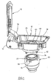
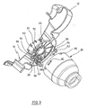
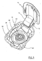
- the Figures show a fuel tank filling tub 10 supporting an arm 14 of a fuel tank cap 16 situated in a lateral extension 12.
- the fuel tank filling tub 10 is fitted with a peripheral, outwardly pointing rim 18.
- the fuel tank filling tub 10 is inserted into an omitted aperture of an omitted automobile body.
- the Figures show a tubular adapter 20 which receives a housing 22 in turn receiving a pivoting lid 24 which is biased by an omitted spring into the closed position and which constitutes a sealing element.
- the lid 24 may be opened by the applied pressure from an omitted fuel pump nozzle.
- Such an adapter is known per se.
- the fuel tank filling tub 10 comprises a circular recess 26 fitted with a hole 28.
- a jar-like housing 30 is mounted in said recess. Said housing is fitted with a circular, outward flange 32 inserted snugly into the recess 26 and resting on the bottom of the recess 26.
- a support plate 36 is configured on the bottom 34 of the recess 26 and is mounted in a clearance of the flange 32 and in this manner is laterally fixed in place.
- An actuation bush 40 rests on said support plate 36 and is fitted within it with a set of tabs 42 constituting a conical insertion zone for a fuel tank nozzle.
- the actuation bush 40 comprises a slot 44 running parallel to the bush axis and thereby allowing radial expansion when the tabs 42 are subjected to axial pressure.
- the basics of such actuation mechanisms already were disclosed in the above cited German patent DE 10 2004 002 994 B3 .
- the actuation bush 40 is seated in the cylindrical portion 46 of the jar-like housing 30 which, in Fig. 2 , by means of an inward-pointing rim 48, constitutes a limit on the actuation bush 40.
- the actuation bush 40 may move slightly both axially and transversely to the axis within the jar-like housing 30.
- Fig. 3 does however show the support plate 36, furthermore a sealing lid 50 fitted with a lateral arm 52 pivotably supported at the bottom 34 of the recess 26 to pivot about an axis parallel to that of the jar-like housing 30.
- Said arm also comprises a longitudinal slot 54 engaged by a first pin 56a.
- a second pin 56 is mounted in an elongated slot 58 of the support plate 36.
- the pins 56, 56a are associated with lateral respectively radial lugs 60, 62 connected at each side of the slot 44 to the actuation bush 40.
- the fuel filling tub is fitted with lugs 62 pointing toward the adapter 20 and comprising an aperture 64.
- the tubular adapter 20 is fitted at its end facing the fuel filling tub 10 with peripheral detent beaks 66 entering the apertures 64 when the adapter 20 is mated to the fuel filling tub 10.
- the fuel filling tub 10 is fitted with a downward-pointing rim 68 which is engaged by a portion of the tubular adapter 10.
- a polarizing beak 70 at the outer side of the tubular adapter 20 cooperates with a clearance 72 in the support plate 36 to allow mating these components in their predetermined relative rotational positions.
Landscapes
- Engineering & Computer Science (AREA)
- Life Sciences & Earth Sciences (AREA)
- Sustainable Development (AREA)
- Sustainable Energy (AREA)
- Chemical & Material Sciences (AREA)
- Combustion & Propulsion (AREA)
- Transportation (AREA)
- Mechanical Engineering (AREA)
- Cooling, Air Intake And Gas Exhaust, And Fuel Tank Arrangements In Propulsion Units (AREA)
Claims (10)
- Kraftstoffeinfüllanordnung zum Füllen von Dieselkraftstoff in einen Fahrzeugtank, die durch die folgenden Merkmale definiert wird:- ein geschlitzter Betätigungsring (40), der aus gefedertem Material hergestellt ist oder radial vorgespannt ist und mit einem parallel zur Ringachse verlaufenden Spalt versehen ist, umfasst einen Einführabschnitt, der sich zu dem Fahrzeugtank hin konisch verjüngt, wobei sein schmaler Querschnitt kleiner ist als der Querschnitt einer Dieselzapfpistole und gleich dem oder größer als der Querschnitt einer Benzinzapfpistole ist,- der Betätigungsring (40) ist an seinem zu dem Kraftstofftank weisenden Ende auf mindestens einer Seite des Spalts mit einem Antriebssegment ausgestattet,- ein topfförmiges Gehäuse (30), in dem der Betätigungsring (40) schwimmend konfiguriert ist, wobei der Außendurchmesser des Betätigungsrings in seinem entspannten Zustand kleiner ist als der Innendurchmesser des topfförmigen Gehäuses,- eine Kraftstofftankmulde (10), die integral aus Kunststoff hergestellt ist und eine Vertiefung (26) aufweist,- einen Verschlussmechanismus (50), der an dem zu dem Kraftstofftank weisenden Ende des Betätigungsrings (40) angebracht ist und dazu ausgeführt ist, in seiner geschlossenen Stellung einen Anschlag für eine eingeführte Zapfpistole zu bilden, und- das Antriebssegment des Betätigungsrings (40) den Verschlussmechanismus in Eingriff nimmt, wodurch dieser Verschlussmechanismus aus der geschlossenen in die geöffnete Stellung bewegt wird, wenn der Betätigungsring durch die Dieselzapfpistole aufgeweitet wird, wobei der Verschlussmechanismus in seiner geschlossenen Stellung den Durchgang zum Tank verschließt,
dadurch gekennzeichnet, dass der Betätigungsring (40), das topfförmige Gehäuse (30) und der Verschlussmechanismus (50) in der Vertiefung (26) der Kraftstofftankmulde (10) angeordnet sind, wobei der Verschlussmechanismus (50) eine Öffnung (28) in der Vertiefung (26) gezielt sperrt oder freigibt, und dass die Anordnung einen rohrförmigen Adapter (20) zwischen der Kraftstofftankmulde (10) und einem Kraftstofftankeinfüllrohr umfasst, wobei der rohrförmige Adapter (20) an seinem zu der Mulde weisenden Ende mit einem federbelasteten Schließglied (24) versehen ist, das mittels einer Zapfpistole geöffnet werden soll. - Kraftstofftankeinfüllanordnung nach Anspruch 1, dadurch gekennzeichnet, dass eine schieberartige Verschlussklappe (50) am Boden der Vertiefung (26) gelagert ist, eine Lagerscheibe (36) sich am Boden der Vertiefung (26) abstützt, der Betätigungsring (40) zwischen der Lagerscheibe (36) und dem Boden der Vertiefung (26) angeordnet ist, wobei das topfförmige Gehäuse am Boden der Vertiefung (26) abgestützt ist.
- Kraftstofftankeinfüllanordnung nach Anspruch 2, dadurch gekennzeichnet, dass die Lagerscheibe (36) in einer Ausnehmung des Flansches (32) des Gehäuses (30) festgelegt ist.
- Kraftstofftankeinfüllanordnung nach Anspruch 2 oder 3, dadurch gekennzeichnet, dass der Flansch (36) passgenau in die Vertiefung (26) eingesetzt ist.
- Kraftstofftankeinfüllanordnung nach einem der Ansprüche 2 bis 4, dadurch gekennzeichnet, dass durch die Vertiefung ein zylindrisches Segment der Kraftstofftankmulde (10) gebildet wird, um das zugekehrte Ende des rohrförmigen Adapters (20) aufzunehmen.
- Kraftstofftankeinfüllanordnung nach einem der Ansprüche 1 bis 5, dadurch gekennzeichnet, dass Orientierungselemente (70, 72) am Adapter (20) und an der Lagerscheibe (36) vorgesehen sind, über welche der Adapter und die Lagerscheibe in einer vorbestimmten relativen Drehlage zusammengefügt werden können.
- Kraftstofftankeinfüllanordnung nach einem der Ansprüche 1 bis 6, dadurch gekennzeichnet, dass an der Kraftstofftankmulde (10) und am rohrförmigen Adapter (20) zusammenwirkende Arretierungsabschnitte (62, 66) konfiguriert sind, um diese Komponenten rastend zusammenzufügen.
- Kraftstofftankeinfüllanordnung nach einem der Ansprüche 1 bis 7, dadurch gekennzeichnet, dass die Verschlussklappe (50) einen seitlichen Arm (52) aufweist, der um eine Achse schwenkbar gelagert ist, die parallel zur Achse des topfförmigen Gehäuses (30) verläuft, und der Arm (52) einen Schlitz (54) aufweist, in den ein erstes Antriebssegment des Betätigungsrings (40) eingreift, während ein zweites Antriebssegment nahezu ortsfest in der Lagerscheibe (36) angeordnet ist.
- Kraftstoffeinfüllanordnung nach Anspruch 8, dadurch gekennzeichnet, dass die Antriebssegmente mit Zapfen (56, 56a) versehen sind, wobei ein Zapfen im Schlitz der Verschlussklappe (50) eingreift und der andere Zapfen in ein Loch (58) eingreift, das eine begrenzte Bewegung des anderen Zapfens gestattet.
- Kraftstoffeinfüllanordnung nach Anspruch 8 oder 9, dadurch gekennzeichnet, dass die Lagerscheibe (36) einen bogenförmigen Schlitz aufweist, durch den hindurch der Zapfen geführt ist, der in Eingriff mit dem Schlitz des Arms der Verschlussklappe (50) steht.
Applications Claiming Priority (2)
| Application Number | Priority Date | Filing Date | Title |
|---|---|---|---|
| DE102006031463A DE102006031463A1 (de) | 2006-07-07 | 2006-07-07 | Einfüllstutzen für das Einfüllen von Dieselkraftstoff in einen Fahrzeugtank |
| PCT/IB2007/001736 WO2008007179A2 (en) | 2006-07-07 | 2007-06-26 | A fuel intake assembly for filling a vehicle tank with diesel fuel |
Publications (2)
| Publication Number | Publication Date |
|---|---|
| EP2038137A2 EP2038137A2 (de) | 2009-03-25 |
| EP2038137B1 true EP2038137B1 (de) | 2010-08-04 |
Family
ID=38779550
Family Applications (1)
| Application Number | Title | Priority Date | Filing Date |
|---|---|---|---|
| EP07804536A Not-in-force EP2038137B1 (de) | 2006-07-07 | 2007-06-26 | Brennstoffeinlassanordnung zur füllung eines fahrzeugtanks mit diesel-brennstoff |
Country Status (6)
| Country | Link |
|---|---|
| US (1) | US20090095373A1 (de) |
| EP (1) | EP2038137B1 (de) |
| JP (1) | JP5027225B2 (de) |
| KR (1) | KR20090033353A (de) |
| DE (2) | DE102006031463A1 (de) |
| WO (1) | WO2008007179A2 (de) |
Families Citing this family (10)
| Publication number | Priority date | Publication date | Assignee | Title |
|---|---|---|---|---|
| JP2009061974A (ja) * | 2007-09-07 | 2009-03-26 | Honda Motor Co Ltd | フューエルリッド部構造 |
| DE112009001823T5 (de) * | 2008-08-20 | 2011-06-01 | Illinois Tool Works Inc., Glenview | Fehlbetankungssperre |
| DE102008039311B4 (de) | 2008-08-22 | 2013-02-21 | Itw Automotive Products Gmbh & Co. Kg | Einfüllstutzen für das Einfüllen von Kraftstoff in einen Fahrzeugtank |
| US10000117B2 (en) | 2012-02-17 | 2018-06-19 | Stant Usa Corp. | Filler neck closure assembly |
| WO2014183121A1 (en) | 2013-05-10 | 2014-11-13 | Stant Usa Corp. | Fuel-dispensing nozzle inhibitor |
| KR101755751B1 (ko) * | 2013-05-28 | 2017-07-07 | 현대자동차주식회사 | 자동차의 혼유방지장치 |
| US9266428B2 (en) | 2014-04-15 | 2016-02-23 | Honda Motor Co., Ltd. | Capless fuel filler assembly for vehicle |
| IT201600104772A1 (it) * | 2016-10-18 | 2018-04-18 | Cebi Italy Spa | Sistema per la chiusura di un portello del serbatoio carburante. |
| US11541746B2 (en) * | 2018-08-24 | 2023-01-03 | Illinois Tool Works Inc. | Oiling or charging port assembly |
| US20230278420A1 (en) * | 2022-03-07 | 2023-09-07 | The Knapheide Manufacturing Company | Fuel fill adaptor assembly for vehicle body |
Family Cites Families (18)
| Publication number | Priority date | Publication date | Assignee | Title |
|---|---|---|---|---|
| JP2528029B2 (ja) * | 1990-08-24 | 1996-08-28 | 豊田合成株式会社 | 燃料注入口 |
| US5275213A (en) * | 1993-01-22 | 1994-01-04 | Perko, Inc. | Fuel filling and venting device |
| JPH06262954A (ja) * | 1993-03-11 | 1994-09-20 | Kiipaa Kk | 燃料タンクの給油口ユニット |
| JP2920226B2 (ja) * | 1994-12-28 | 1999-07-19 | 本田技研工業株式会社 | 蒸発燃料放出抑制装置 |
| JP2000016097A (ja) * | 1998-06-30 | 2000-01-18 | Honda Motor Co Ltd | 燃料タンクのフィラーパイプ用チェックバルブ |
| US6763966B2 (en) * | 2000-09-18 | 2004-07-20 | Stant Manufacturing Inc. | Torque-limit signal system for filler neck cap |
| JP4566433B2 (ja) * | 2001-03-22 | 2010-10-20 | 株式会社Fts | 燃料タンクのインレットパイプ接合構造 |
| FR2827818B1 (fr) * | 2001-07-25 | 2003-10-24 | Inergy Automotive Systems Man | Systeme d'obturation pour tubulure de remplissage de reservoir a carburant et procede pour ouvrir cette tubulure |
| US6539990B1 (en) * | 2001-11-20 | 2003-04-01 | Illinois Tool Works Inc. | Capless refueling assembly |
| DE10307355B4 (de) * | 2003-02-21 | 2006-02-09 | Itw Automotive Products Gmbh & Co. Kg | Verschlußvorrichtung für ein Einfüllrohr eines Automobiltanks |
| FR2861382B1 (fr) * | 2003-10-22 | 2005-12-30 | Staubli Sa Ets | Dispositif de remplissage de reservoir de vehicule en carburant liquide |
| FR2861655B1 (fr) * | 2003-10-31 | 2006-01-06 | Inergy Automotive Systems Res | Dispositif d'obturation d'une tubulure de remplissage d'un reservoir a liquide, reservoir equipe d'un tel dispositif et vehicule automobile comprenant un tel reservoir |
| DE102004002994B3 (de) * | 2004-01-19 | 2005-09-22 | Itw Automotive Products Gmbh & Co. Kg | Einfüllstutzen für das Einfüllen von Kraftstoff in einen Fahrzeugtank |
| US6945290B1 (en) * | 2004-06-10 | 2005-09-20 | Eaton Corporation | Check valve for use in filler tube vapor recirculation system and method of making same |
| JP4397747B2 (ja) * | 2004-07-05 | 2010-01-13 | 日立建機株式会社 | 建設機械の燃料給油器具 |
| US7302977B2 (en) * | 2004-09-30 | 2007-12-04 | Stant Manufacturing Inc. | Fuel-dispensing nozzle inhibitor |
| DE102005004551A1 (de) * | 2005-01-31 | 2006-08-10 | Kautex Textron Gmbh & Co. Kg | Auslaufstutzen |
| FR2901191B1 (fr) * | 2006-05-22 | 2008-12-26 | Inergy Automotive Systems Res | Systeme d'obturation pour tubulure de remplissage de reservoir a carburant |
-
2006
- 2006-07-07 DE DE102006031463A patent/DE102006031463A1/de not_active Withdrawn
-
2007
- 2007-06-26 DE DE602007008246T patent/DE602007008246D1/de active Active
- 2007-06-26 JP JP2009518990A patent/JP5027225B2/ja not_active Expired - Fee Related
- 2007-06-26 WO PCT/IB2007/001736 patent/WO2008007179A2/en active Application Filing
- 2007-06-26 KR KR1020097000138A patent/KR20090033353A/ko not_active Application Discontinuation
- 2007-06-26 US US12/297,684 patent/US20090095373A1/en not_active Abandoned
- 2007-06-26 EP EP07804536A patent/EP2038137B1/de not_active Not-in-force
Also Published As
| Publication number | Publication date |
|---|---|
| EP2038137A2 (de) | 2009-03-25 |
| DE102006031463A1 (de) | 2008-01-10 |
| WO2008007179A2 (en) | 2008-01-17 |
| JP2009542525A (ja) | 2009-12-03 |
| KR20090033353A (ko) | 2009-04-02 |
| JP5027225B2 (ja) | 2012-09-19 |
| DE602007008246D1 (de) | 2010-09-16 |
| WO2008007179A3 (en) | 2008-03-13 |
| US20090095373A1 (en) | 2009-04-16 |
Similar Documents
| Publication | Publication Date | Title |
|---|---|---|
| EP2038137B1 (de) | Brennstoffeinlassanordnung zur füllung eines fahrzeugtanks mit diesel-brennstoff | |
| CA2226028C (en) | Fuel filler assembly, particularly for a motor vehicle | |
| JP5596712B2 (ja) | 給油ミス防止装置 | |
| US7950425B2 (en) | Filler neck to fill fuel into a vehicle tank | |
| EP1838546B1 (de) | Führungsbewegung eines deckellosen einfüllstutzenverschlusses | |
| EP1738950B1 (de) | Kraftstoff-Einfüllstutzen für ein Fahrzeug | |
| US20080237231A1 (en) | Filler neck of a fuel tank with an arrangement for preventing incorrect fueling | |
| JP2006206042A (ja) | 吐出側連結管 | |
| EP1799551A1 (de) | Kraftfahrzeug-kraftstoffzufuhrsystem ohne deckel | |
| EP3269577A1 (de) | Betankungsabschnittsstruktur eines kraftstofftanks | |
| JP6213412B2 (ja) | 燃料タンクの開閉装置 | |
| JP6682364B2 (ja) | ハウジングユニット及び開閉体のロック装置 | |
| US6253788B1 (en) | Check valve for use in a filler pipe for filling a fuel tank | |
| JP2018052450A (ja) | 給油口開閉構造 | |
| US6991006B2 (en) | Closing device for a filing tube of a fuel tank in an automobile | |
| EP2837518B1 (de) | Aufbau einer kraftstoffeinfüllöffnung für einen kraftstofftank | |
| WO2010133960A1 (en) | Flexible dust door for capless refueling system | |
| US20090139606A1 (en) | Contoured door with seal | |
| JP3952657B2 (ja) | タンク用キャップ | |
| CA2481985A1 (en) | Fuel vapor vent valve and method of attaching same to a tank | |
| JP4854473B2 (ja) | 逆止弁 | |
| US20160001653A1 (en) | Draining fuel nozzle-receiving assembly | |
| US11142063B2 (en) | Filler neck for filling an operating substance or additive into a vehicle tank by means of a fuel pump nozzle | |
| JPH02299930A (ja) | フラップバルブ装置 | |
| JP4484749B2 (ja) | 逆止弁 |
Legal Events
| Date | Code | Title | Description |
|---|---|---|---|
| PUAI | Public reference made under article 153(3) epc to a published international application that has entered the european phase |
Free format text: ORIGINAL CODE: 0009012 |
|
| 17P | Request for examination filed |
Effective date: 20081118 |
|
| AK | Designated contracting states |
Kind code of ref document: A2 Designated state(s): AT BE BG CH CY CZ DE DK EE ES FI FR GB GR HU IE IS IT LI LT LU LV MC MT NL PL PT RO SE SI SK TR |
|
| AX | Request for extension of the european patent |
Extension state: AL BA HR MK RS |
|
| DAX | Request for extension of the european patent (deleted) | ||
| RBV | Designated contracting states (corrected) |
Designated state(s): DE FR IT |
|
| 17Q | First examination report despatched |
Effective date: 20090716 |
|
| RAP1 | Party data changed (applicant data changed or rights of an application transferred) |
Owner name: ITW AUTOMOTIVE PRODUCTS GMBH & CO. KG |
|
| GRAP | Despatch of communication of intention to grant a patent |
Free format text: ORIGINAL CODE: EPIDOSNIGR1 |
|
| GRAS | Grant fee paid |
Free format text: ORIGINAL CODE: EPIDOSNIGR3 |
|
| GRAA | (expected) grant |
Free format text: ORIGINAL CODE: 0009210 |
|
| AK | Designated contracting states |
Kind code of ref document: B1 Designated state(s): DE FR IT |
|
| REF | Corresponds to: |
Ref document number: 602007008246 Country of ref document: DE Date of ref document: 20100916 Kind code of ref document: P |
|
| PG25 | Lapsed in a contracting state [announced via postgrant information from national office to epo] |
Ref country code: IT Free format text: LAPSE BECAUSE OF FAILURE TO SUBMIT A TRANSLATION OF THE DESCRIPTION OR TO PAY THE FEE WITHIN THE PRESCRIBED TIME-LIMIT Effective date: 20100804 |
|
| PLBE | No opposition filed within time limit |
Free format text: ORIGINAL CODE: 0009261 |
|
| STAA | Information on the status of an ep patent application or granted ep patent |
Free format text: STATUS: NO OPPOSITION FILED WITHIN TIME LIMIT |
|
| 26N | No opposition filed |
Effective date: 20110506 |
|
| REG | Reference to a national code |
Ref country code: DE Ref legal event code: R097 Ref document number: 602007008246 Country of ref document: DE Effective date: 20110506 |
|
| REG | Reference to a national code |
Ref country code: FR Ref legal event code: ST Effective date: 20120229 |
|
| REG | Reference to a national code |
Ref country code: DE Ref legal event code: R119 Ref document number: 602007008246 Country of ref document: DE Effective date: 20120103 |
|
| PG25 | Lapsed in a contracting state [announced via postgrant information from national office to epo] |
Ref country code: FR Free format text: LAPSE BECAUSE OF NON-PAYMENT OF DUE FEES Effective date: 20110630 Ref country code: DE Free format text: LAPSE BECAUSE OF NON-PAYMENT OF DUE FEES Effective date: 20120103 |