EP2034889B1 - Rotatable mri scanner for diagnostic and surgical imaging applications - Google Patents
Rotatable mri scanner for diagnostic and surgical imaging applications Download PDFInfo
- Publication number
- EP2034889B1 EP2034889B1 EP07719993.3A EP07719993A EP2034889B1 EP 2034889 B1 EP2034889 B1 EP 2034889B1 EP 07719993 A EP07719993 A EP 07719993A EP 2034889 B1 EP2034889 B1 EP 2034889B1
- Authority
- EP
- European Patent Office
- Prior art keywords
- magnet
- patient
- pet
- room
- imaging
- Prior art date
- Legal status (The legal status is an assumption and is not a legal conclusion. Google has not performed a legal analysis and makes no representation as to the accuracy of the status listed.)
- Active
Links
Images



Classifications
-
- A—HUMAN NECESSITIES
- A61—MEDICAL OR VETERINARY SCIENCE; HYGIENE
- A61B—DIAGNOSIS; SURGERY; IDENTIFICATION
- A61B5/00—Measuring for diagnostic purposes; Identification of persons
- A61B5/70—Means for positioning the patient in relation to the detecting, measuring or recording means
- A61B5/704—Tables
-
- A—HUMAN NECESSITIES
- A61—MEDICAL OR VETERINARY SCIENCE; HYGIENE
- A61B—DIAGNOSIS; SURGERY; IDENTIFICATION
- A61B5/00—Measuring for diagnostic purposes; Identification of persons
- A61B5/0033—Features or image-related aspects of imaging apparatus, e.g. for MRI, optical tomography or impedance tomography apparatus; Arrangements of imaging apparatus in a room
- A61B5/0035—Features or image-related aspects of imaging apparatus, e.g. for MRI, optical tomography or impedance tomography apparatus; Arrangements of imaging apparatus in a room adapted for acquisition of images from more than one imaging mode, e.g. combining MRI and optical tomography
-
- A—HUMAN NECESSITIES
- A61—MEDICAL OR VETERINARY SCIENCE; HYGIENE
- A61B—DIAGNOSIS; SURGERY; IDENTIFICATION
- A61B5/00—Measuring for diagnostic purposes; Identification of persons
- A61B5/05—Detecting, measuring or recording for diagnosis by means of electric currents or magnetic fields; Measuring using microwaves or radio waves
- A61B5/055—Detecting, measuring or recording for diagnosis by means of electric currents or magnetic fields; Measuring using microwaves or radio waves involving electronic [EMR] or nuclear [NMR] magnetic resonance, e.g. magnetic resonance imaging
-
- G—PHYSICS
- G01—MEASURING; TESTING
- G01R—MEASURING ELECTRIC VARIABLES; MEASURING MAGNETIC VARIABLES
- G01R33/00—Arrangements or instruments for measuring magnetic variables
- G01R33/20—Arrangements or instruments for measuring magnetic variables involving magnetic resonance
- G01R33/28—Details of apparatus provided for in groups G01R33/44 - G01R33/64
-
- G—PHYSICS
- G01—MEASURING; TESTING
- G01R—MEASURING ELECTRIC VARIABLES; MEASURING MAGNETIC VARIABLES
- G01R33/00—Arrangements or instruments for measuring magnetic variables
- G01R33/20—Arrangements or instruments for measuring magnetic variables involving magnetic resonance
- G01R33/28—Details of apparatus provided for in groups G01R33/44 - G01R33/64
- G01R33/38—Systems for generation, homogenisation or stabilisation of the main or gradient magnetic field
-
- G—PHYSICS
- G01—MEASURING; TESTING
- G01R—MEASURING ELECTRIC VARIABLES; MEASURING MAGNETIC VARIABLES
- G01R33/00—Arrangements or instruments for measuring magnetic variables
- G01R33/20—Arrangements or instruments for measuring magnetic variables involving magnetic resonance
- G01R33/44—Arrangements or instruments for measuring magnetic variables involving magnetic resonance using nuclear magnetic resonance [NMR]
- G01R33/48—NMR imaging systems
- G01R33/4808—Multimodal MR, e.g. MR combined with positron emission tomography [PET], MR combined with ultrasound or MR combined with computed tomography [CT]
- G01R33/481—MR combined with positron emission tomography [PET] or single photon emission computed tomography [SPECT]
Definitions
- This invention relates to a movable apparatus for obtaining medical scanned images of a patient.
- the apparatus may provide the possibility for combining and sequencing both PET and MRI detection capability for surgical imaging applications.
- the apparatus may provide movement in both translational and rotational directions to optimize the utility and effectiveness of the system.
- PET Positron Emission Tomography
- MRI Magnetic Resonance Imaging
- PET a solution is injected or taken into the body, the solution which contains molecules with positron emitting atoms. Therefore, once positron detector geometry is properly positioned around the patient, and once software is used to identify the location of the positron emission, the location and concentration of positron emitting molecules can be detected.
- One of the major molecules used is a derivative of glucose which can enter the cells as glucose but is not metabolised as glucose and so the regions of major activity in the body can be detected. If the molecules are specific for cancer then this imaging technique can be utilised to detect the location of the tumour.
- PET does not provide any anatomical information, only information on the location of the positron emitting molecules. The PET images need to registered to the anatomy of the patient and this is where MRI can be very useful.
- MRI Magnetic resonance Imaging
- a high field magnet typically superconducting
- the magnetic field allows a pulsed and sequenced magnetic and EM field to probe the body to produce soft tissue images, which allow the trained radiologist to determine with high probability the anatomy of the patient.
- MRI is sometimes performed using contrast agents to provide even better contrast between different soft tissue types. MRI techniques are very good at detecting the anatomical location of many but not all tumours.
- MRI and PET are orthogonal techniques, in that the PET detection technology can be constructed in such a way that it is unaffected by magnetic fields and the MRI system can be constructed to be unaffected by the PET techniques. For this reason, if an integrated PET and MRI detector system can be constructed, then the two systems can be operated in parallel or almost parallel manners in both space and time to allow for improved and more complete detection of tumour locations within the body.
- PET and MRI can be used to obtain a functional image combined with anatomical image to provide the clinician with far more information than either technique alone.
- positron emitting molecules can be developed which interact only with certain receptors in the brain and so these receptors can be observed by PET and then their actual location in the brain determined by the MRI.
- PET imaging is also an established technique, with general knowledge being available as well as many patents on specific configurations of PET detectors.
- the MRI system consists of:
- the European patent application EP 1 027 862 A1 relates to an apparatus for magnetic resonance imaging and discloses that the apparatus is movable with respect to the examination room and the patient.
- the US patent US 5,842,9897 relates to a simulated patient setup for medical imaging with increased patient throughput and teaches that the patient is lying on preliminary imaging tables and can be transported from tables to tables by sliding of a flat table insert.
- One table is a diagnostic table carried by the magnet which can be extended into a room where the patient lies on the diagnostic table and imaging is performed.
- the other table is a surgical table which remains in place in the room for relative movement of the magnet which can be extended into a room where the patient lies on the surgical table and imaging is performed.
- the magnet may be arranged to carry a diagnostic table at one end and to co-operate with a surgical table at the other end.
- an apparatus for obtaining a scanned image according claim 1 which further comprises a positron emission tomography scanning system (PET) mounted on the magnet for use in conjunction with the magnetic resonance imaging system.
- PET positron emission tomography scanning system
- the PET system is movable.
- the PET system is mounted on the magnet for common movement therewith.
- the magnet is movable longitudinally along its axis.
- the magnet is movable vertically.
- the magnet is rotatable about a vertical axis through 180 degrees.
- the PET system is mounted in the bore of the magnet for common movement therewith.
- the PET system is mounted such that the field of view of the magnet coincides with the field of view of the PET.
- the PET system is movable within the bore.
- the PET system is mounted on the magnet at one end such that movement of the magnet carries the PET to a position aligned with the part of the patient.
- the magnet is rotatable about a vertical axis to move the PET to a position adjacent the patient.
- the PET includes optical fibers extending along the bore to carry optical signals from the scintillation detectors to an exterior control system.
- the PET includes a wireless communication system to carry optical signals from the scintillation detectors to an exterior control system.
- the magnet is mounted on a rail system and the PET system is mounted on same rail system for separate movement of the PET system relative to the magnet.
- the system is installed in renovated hospital buildings or in new buildings.
- the system can be installed in one-room or two-room configurations.
- the magnet and MRI system is shared between the two rooms as needed by the hospital staff, leading to increased cost effectiveness within the business case.
- any design of the integrated PET/MRI scanner should move the scanner instead of moving the patient. This movement of the scanner could be in whole or in part, as long as the patient does not move. This same restriction on usage may eventually be true of interventional approaches, in that some interventional techniques require a significant number of penetrations of the body or aligned equipment items, which infer that patient movement should not be done.
- the MRI system has a magnetic field which is not equivalent in all directions with the magnetic field strength along the axis being different than in the two orthogonal directions. This means that the PET imaging portion of the system may be optimally sited on an off-axis orientation, which implies that rotation of the integrated scanner may be important.
- the present arrangement moves the MRI in rotational and vertical directions as well to ensure that the integrated scanner is optimized.
- One embodiment assumes the presence of a scanner system that integrates both MRI and PET capability, and patents the movement of the integrated scanner in each of the six degrees of freedom of movement for the surgical, interventional and diagnostic imaging environments.
- the magnet system moves into a room within 1 minute, and the doors open within seconds, so the limiting factor on effectiveness of usage of the magnet system is providing the patients into and out of the room, prepping the patients if required, and discussing the imaging with the patients. It is known that a reasonable amount of time per imaging event is 60 minutes, and therefore the movement of the MRI scanner into and out of a room is not the limiting time value. As well, the efficiency of a multi-room system becomes more difficult to schedule as the need for both diagnostic and interventional procedures occurs.
- the following configurations are now possible: A three room diagnostic configuration in which a central magnet holding bay houses the magnet and the diagnostic patients are organized in the three rooms.
- the magnet holding bay becomes part of room one, the magnet does not move but may extend its diagnostic table, the patient lies on the diagnostic table, imaging is performed, no need to do intervention is found, the patient exits the diagnostic table and the magnet moves back into the holding bay, ready for use by one of the other rooms.
- the magnet then may draw in its table, rotates to the doors for that room, and the process for the other room begins. In this case, the magnet does not move in a translational direction, such as on rails, but simply rotates.
- a two room system which is in the corner of the hospital.
- the magnet both rotates and translates.
- This approach allows existing diagnostic functionality and applications to be used in either room, or allows both rooms to serve as intra-operative rooms without any significant change to magnet controls and monitoring.
- This two room corner system cannot be done without a rotating magnet.
- any room configuration which is not of the in-line variety needs to have a rotating magnet.
- in-line configurations can have increased flexibility as well if rotation is allowed.
- PET Imaging can be done in one room, followed by MRI imaging in an adjacent room, based on the needs of the patient and surgical team, thus increasing the financial payback of the medical installation.
- More flexible PET and MR integration can be considered, in that when imaging a floppy gland during surgery no patient movement is required in order to perform imaging on multiple body sites.
- simultaneous or near simultaneous imaging can provide information on more than one location within the body without moving the magnet.
- the surgical team can image the same body part by first imaging using MRI capability and than move the magnet to achieve PET imaging capability of the same body part, thus allowing a flexibility of design for positioning the PET scintillators relative to the center of the field of view of the magnet.
- both PET and MRI detectors are designed as separate subsystems, but placed on the same rail system, it is possible to allow a given operating room to have independent PET and MRI detection applications at different times during the day.
- the MRI and PET detectors can be used separately with a non-moving patient through the rotational and translational movement of the scanner system.
- the patient might be having an MRI scan, something is observed, after which the magnet is removed from the patient, the magnet is then rotated so that the PET system is pointed towards the patient, after which the PET system is moved over the patient, and the PET imaging is performed.
- the magnetic field of the MRI system for axial and non-axially oriented equipment elements which causes the rotational ability of the scanner system to be important.
- the shimming effort required to provide the magnetic system with a homogenous environment is greatly reduced.
- the rebar in the floor makes a difference to the magnetic imaging system, unless it is stainless steel. If the MRI system can be moved in a multitude of manners, it is possible to find the optimum location within the room to provide imaging.
- the PET system may be part of the bore system of the MRI, and can be moved relative to the field of view of the MRI. This movement relative to the MRI field of view may allow better or improved imaging performance.
- the PET focus area and the MRI field of view can be co-located through the design and configuration of the systems.
- the integrated PET/MRI system can be suspended from the ceiling or mounted on a floor mounted bearing, with either system providing rotation of the magnet.
- the MRI system may also be suspended from the ceiling on rails, such that it can also be translated in space using the rail system.
- the rotational mechanism can either be located between the magnet and the rails, or above the rails.
- the below track and above track rotators have different properties for different configurations. The below track rotator allows for easiest upgrade of existing sites, whereas the above track rotator works like a roundhouse in a railway yard, in that the rail, MRI system and all associated systems are rotated.
- Figure 1 shows the integrated PET/MRI scanner with rotating capacity.
- Ceiling rails 1 are bolted onto the structural steel of the building using Rail Clamps 17. Two ceiling rails are used, at a width apart approximately the same as the width of the magnet, although other widths are possible.
- the magnet 3 is mounted onto the rails using a magnet Mover System 2.
- the upper part of the magnet Mover System traverses the rails, and does not rotate.
- the lower part of the magnet Mover System is connected to Slew Ring 11 so that it can rotate relative to the upper part.
- the Slew Ring 11 is motor driven, and carefully rotates the magnet system over a given angle, such as 90 degrees, 180 degrees or 270 degrees depending on the type of room layout being implemented.
- the motor drive system can include gentle acceleration and deceleration in keeping with the requirements of the magnet system.
- the lower part of the magnet Mover System is bolted to the magnet using the Rotator to Magnet System 12.
- a Cable Management System 19 that contains multiple tube guides, with different guides being used for communication cabling, power cabling, low voltage cabling, monitoring cabling and helium lines. The separation of these cables and the guidance of these cables through the rotational movement ensures that no binding and eventual breakage occurs. Again these components pass through the slew ring and connect to components carried on the rails with the movement of the magnet by a cable carrier system 9.
- the magnet Mover System is moved via the belt drive translational system 18.
- This system uses wheels on top of the rail to carry the weight, and Drive Wheels 20 below the rail and contacted with the rail to allow movement to occur.
- Drive wheels and weight bearing wheels are placed on both of the rails, to ensure an even distribution of weight and a straight tracking performance for the system.
- a driveshaft may be used between the left and right belt drive translational systems to ensure that they move in harmony. In this case, a single motor may be used to drive both drive wheel sets.
- a Hand Crank 15 that allows the operators to remove the magnet from the patient if this movement is required. Operation of the hand crank requires the clutch to be disengaged in this particular design.
- the magnet has a round magnet bore 8 into which the table and patient can be positioned to allow imaging to occur.
- the MRI Bore is 70 cm in diameter and approximately 125 cm in length.
- the magnet has a field of view 4 of 30 cm X 45 cm X 45 cm.
- the field of view is the volume within the system that allows high quality imaging to occur, and coincides with the volume over which the magnet field can be maintained within appropriate linearity.
- the patient's anatomy of interest is positioned within the field of view to allow imaging to occur.
- a PET Detector Ring 5 is co-located with the magnet field of view, with each individual detector on the ring being connected via optical fiber in a bundle of fibers 6 to the multipliers 7 that are located above or around the magnet.
- the multipliers are shown on the top of the magnet, however they could be placed in alternative positions within the magnet.
- the optical fiber is wound in the cable carrier 9 which typically carries magnet and associated cables 10 that include quench tube, helium lines, water coolant lines, gradient cables, RF cables, control lines, and a variety of additional monitoring and sensing lines as required for various applications that are attached to the bore, cover-set, and other MRI elements.
- the cable carrier and associated cabling uses the cable carrier guides 16 to maintain the correct shape of the cables as they are moved with the system.
- Figure 1 shows an integrated PET/MRI scanner suitable for simultaneous scanning, because the PET imaging volume, which is inside the PET detector ring, overlaps the MRI field of view.
- Figure 1 has shown a rotational PET/MRI scanner, it is possible to build a rotational MRI scanner for purely MRI scanning needs so that the same construction can be used with the PET scanner omitted.
- FIG 3 shows further details of the movable PET scanner suitable for simultaneous scanning, and is equivalent to the PET/MRI configuration of Figures 1 and 2 .
- the PET detector ring is mounted to move inside the bore.
- the magnet Bore 8 has five spacing and drive rails 32, onto which is fitted the pet detector ring 5.
- This pet detector ring is driven back and forth through the bore using the drive rails 32, but the diagnostic or operating table 34 is sized such that no collision occurs as these elements are being moved inside the bore.
- the PET detector ring 5 has on its inside circumference a multitude of individual PET detectors 55 which generate their output, typically through scintillation, with this output being passed into optical fibers 6 which allow transmission from the scintillator detectors to the multipliers 7.
- optical fiber management system can accommodate the slack.
- the patient enters only from the opposite end of the bore 8, because the other end is used for optical fiber management.
- more sophisticated optical fiber management can be provided to allow both ends of the PET/MRI integrated scanner to be used.
- An alternative design to those above can use wireless transmission of optical signals, with the bore having clear areas within its design which allows for light to pass through.
- the PET detector ring generates EM wavelength suitable for optical fiber to transmit directly into the optical fiber and on to the multiplier.
- a system in which the PET scanner and magnet field of view are fixed in position relative to each other, with the entire integrated scanner moving instead.
- the integrated scanner moves on the ceiling rails, and rotates or moves vertically, in the manner that has already been discussed.
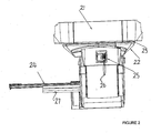
- FIG. 2 shows a rotational MRI shielding cover-set.
- Conventional designs for such covers for magnets used in MRI are well known by persons skilled in the art.
- This cover-set is designed with an upper portion 21 which does not rotate and a lower portion 22 which does rotate, with the two portions being separated at a rotational seam 23.
- Figure 2 also shows a configuration which uses a diagnostic table 24 extending from the left side of the magnet.
- the diagnostic table is attached to the magnet and can move in and out of the magnet for diagnostic imaging.
- the figure also shows the control panel 25 for the system. In this case, there is a set of controls installed on the magnet which includes a pendant control 26 connected to the magnet by a cable.
- Figure 4 shows a floor layout in which the translating, rotating and vertically moving scanner is used in a two room configuration to service both an adult and a child, and shows a two room layout in which first room 41 is separated from second room 42 via sliding doors 43, with patients and medical team accessing the rooms via patient entry doors 44.
- the integrated scanner can move between these two rooms.
- Figure 4 shows two positions for this integrated scanner.
- the rails 1 allow the scanner to move between the rooms.
- the scanner position in room 41 is shown as it moves towards the surgical imaging position, in which the scanner 3 moves over the table 50 and in which the Siemens diagnostic table 24 is attached to the rear of the scanner as is the custom with the Siemens Espree (trademark), for example.
- This same scanner when required, can be moved to a second position in room 42 in which the scanner 3 is rotated to allow the diagnostic table 24 to be positioned for interventional work. This rotation increases the utility of the system by minimizing the amount of space and access required in the second room 42.
- the movement of the imaging system between the two rooms will increase the complexity of the shimming requirements of the MRI system, that is the difficulty of providing shielding for the signals and magnetic field required for the MRI experiments. Also, even if the particular locations within the various rooms are difficult to shim for MRI usage, those locations can be still be used for PET imaging, leading to an increased utility of the system in various room configurations.
- Figure 5 shows a three room diagnostic configuration in which a central magnet holding bay 60 houses the magnet 61 and the diagnostic patients are organized in the three rooms 62, 63 and 64.
- the doors 65 to one of the rooms 62 can be opened for example by retraction to one side so that the magnet holding bay becomes part of that room 62, the magnet does not move but may extend its diagnostic table 66, the patient lies on the diagnostic table, imaging is performed, no need to do intervention is found, the patient exits the diagnostic table and the magnet moves back into the holding bay, ready for use by one of the other rooms.
- the magnet then may draw in its table 66, rotates to the doors for that room, and the process for the other room begins. In this case, the magnet does not move in a translational direction, such as on rails, but simply rotates.
- the front face can carry a PET scanning system so that the PET can be moved into position if required. If there is no PET system used, the front face may be arranged so that the magnet is not symmetrical and requires that the front face be moved into the position of the patient.
- the magnet is mounted on a rail system along which can roll a support and on which is carried the slew ring allowing the magnet to rotate about its vertical axis. In this way the front face of the magnet can be moved to face the room.
- the patient table is located in the respective room so that the magnet moves to and relative to the table.
- in-line configurations can have increased flexibility as well if rotation is allowed.
- the magnet may be arranged to carry a diagnostic table at one end such that on entry into a diagnostic room or on rotation of the magnet to co-operate with that diagnostic room, the table is made available for patients in that room.
- the magnet in a surgical situation is arranged to co-operate with a table present in the room which remains in the room when the magnet is moved so as to allow surgery to continue.
- the magnet may carry the table at one end and be arranged to co-operate with a surgical table at the other end, thus requiring rotation of the table about its vertical axis.
- the methods that can be used to limit this effect include: standard techniques that use additional metal in the walls to provide shielding, use of active coils embedded in the walls that turn on only when the rotational action occurs, power cycling of the MRI active coils, in which the active coils on the magnet either are increased or decreased in current so that the field does not extend so far.
- Cable routing design in which the cabling is designed to be rotated 180 degrees.
- One method of doing the cable routing is to pre-route the cabling 90 degrees, and then the maximum cable bending is +/- 90 degrees to achieve the full 180 degrees rotation.
- the cables are usually at the 90 degrees bend radius during their lifetime.
- the arrangement described herein provides the following features and advantages:
- the diagnostic table For the Espree magnet, it is useful to pull in the diagnostic table prior to rotation, to allow for a minimum radius of rotation, a minimum strain on the rotating motor, and a maximum for operator safety. If the diagnostic table would extend further out of the magnet, it would increase the probability of collision between the operator and the rotating system, or the collision between the rotating system and equipment items inside the room.
- the cover-set of the magnet along with the brackets that holds the cover-set onto the magnet provide an upper part of the cover-set which does not rotate and a lower part of the cover-set that does rotate with the magnet.
- a motor system that gently accelerates and decelerates in a programmed and programmable way. If the start and stop forces that are exerted on the magnet are excessive, vibration can be caused and potentially shorter life can occur.
- control system includes "lock-outs" that will not allow the rotation to occur unless the proper orientation, location, door condition or other specific conditions are met by the environment. This lock-out capability ensures that the magnet cannot be rotated if the environment is not ready to receive the rotation.
Landscapes
- Health & Medical Sciences (AREA)
- Physics & Mathematics (AREA)
- Life Sciences & Earth Sciences (AREA)
- Nuclear Medicine, Radiotherapy & Molecular Imaging (AREA)
- Engineering & Computer Science (AREA)
- General Health & Medical Sciences (AREA)
- Radiology & Medical Imaging (AREA)
- Medical Informatics (AREA)
- Public Health (AREA)
- Biophysics (AREA)
- Biomedical Technology (AREA)
- Heart & Thoracic Surgery (AREA)
- Veterinary Medicine (AREA)
- Molecular Biology (AREA)
- Surgery (AREA)
- Animal Behavior & Ethology (AREA)
- Pathology (AREA)
- Condensed Matter Physics & Semiconductors (AREA)
- General Physics & Mathematics (AREA)
- Pulmonology (AREA)
- Theoretical Computer Science (AREA)
- High Energy & Nuclear Physics (AREA)
- Magnetic Resonance Imaging Apparatus (AREA)
- Nuclear Medicine (AREA)
Applications Claiming Priority (2)
| Application Number | Priority Date | Filing Date | Title |
|---|---|---|---|
| US80524106P | 2006-06-20 | 2006-06-20 | |
| PCT/CA2007/001077 WO2007147233A1 (en) | 2006-06-20 | 2007-06-20 | Rotatable integrated scanner for diagnostic and surgical imaging applications |
Publications (3)
| Publication Number | Publication Date |
|---|---|
| EP2034889A1 EP2034889A1 (en) | 2009-03-18 |
| EP2034889A4 EP2034889A4 (en) | 2012-10-10 |
| EP2034889B1 true EP2034889B1 (en) | 2020-08-05 |
Family
ID=38833014
Family Applications (1)
| Application Number | Title | Priority Date | Filing Date |
|---|---|---|---|
| EP07719993.3A Active EP2034889B1 (en) | 2006-06-20 | 2007-06-20 | Rotatable mri scanner for diagnostic and surgical imaging applications |
Country Status (5)
| Country | Link |
|---|---|
| US (2) | US8295905B2 (https=) |
| EP (1) | EP2034889B1 (https=) |
| JP (1) | JP2009540882A (https=) |
| CA (1) | CA2651047C (https=) |
| WO (1) | WO2007147233A1 (https=) |
Families Citing this family (35)
| Publication number | Priority date | Publication date | Assignee | Title |
|---|---|---|---|---|
| KR100791021B1 (ko) * | 2006-08-18 | 2008-01-07 | 가천의과학대학교 산학협력단 | Petmri 퓨전영상시스템 |
| DE102008009674A1 (de) | 2008-02-18 | 2009-08-20 | Siemens Aktiengesellschaft | Magnetresonanz-Anlage |
| DE102008009673A1 (de) | 2008-02-18 | 2009-08-20 | Siemens Aktiengesellschaft | Magnetresonanz-Anlage |
| JP5390539B2 (ja) * | 2008-02-25 | 2014-01-15 | コーニンクレッカ フィリップス エヌ ヴェ | 放射線検出器に対する等角面のバックボーン |
| US8369929B2 (en) | 2008-06-04 | 2013-02-05 | Imris Inc. | Patient support table for use in magnetic resonace imaging |
| US8190235B2 (en) | 2008-06-04 | 2012-05-29 | Imris Inc. | System for magnetic resonance and X-Ray imaging |
| DE102008033983B4 (de) * | 2008-07-21 | 2012-08-09 | Siemens Aktiengesellschaft | Magnetresonanz-Single-Photon-Emissions-Computertomographie-Gerät |
| GB2465556B (en) * | 2008-11-19 | 2011-06-22 | Siemens Magnet Technology Ltd | Cryostat suspension system with turret mount |
| US8245335B2 (en) | 2009-03-30 | 2012-08-21 | Imns Inc. | Support component for use in imaging by magnetic resonance and x-ray |
| DE102009030714A1 (de) * | 2009-06-26 | 2010-12-30 | Siemens Aktiengesellschaft | Verfahren zur Absorptionskorrektur von PET-Daten und MR-PET-Anlage |
| JP5598956B2 (ja) | 2010-03-09 | 2014-10-01 | 独立行政法人放射線医学総合研究所 | Pet/mri装置 |
| RU2587077C2 (ru) * | 2010-12-16 | 2016-06-10 | Конинклейке Филипс Электроникс Н.В. | Система планирования лучевой терапии и последующего наблюдения с ширококанальной радиуноклидной и магнитно-резонансной визуализацией или ширококанальной компьютерной томографией и магнитно-резонансной визуализацией |
| US20120151677A1 (en) * | 2010-12-20 | 2012-06-21 | General Electric Company | Method and system for cable management |
| DE102011005435A1 (de) * | 2011-03-11 | 2012-09-13 | Siemens Aktiengesellschaft | Verfahren zur Ermittlung eines PET-Bilddatensatzes |
| US8584274B2 (en) | 2011-04-22 | 2013-11-19 | Medtrak Holding Company, Llc | Patient support and transport system |
| US8555578B2 (en) | 2011-04-22 | 2013-10-15 | Medtrak Holding Company, Llc | Shielded movable door element of a multimodality medical suite |
| US8898830B2 (en) | 2011-04-22 | 2014-12-02 | Medtrak Holding Company, Llc | Patient support and transport system of a multimodality medical suite |
| WO2012171029A1 (en) * | 2011-06-09 | 2012-12-13 | The Regents Of The University Of California | Excised specimen imaging using a combined pet and micro ct scanner |
| KR101242500B1 (ko) * | 2011-06-27 | 2013-03-12 | 한국과학기술원 | Pet-mri 융합시스템 |
| US9204818B2 (en) | 2012-01-16 | 2015-12-08 | Imris Inc | Drive system for a head clamp for use in imaging by Magnetic Resonance and X-ray |
| JP2013228226A (ja) | 2012-04-24 | 2013-11-07 | Toshiba Corp | Pet−mri装置 |
| US9265440B2 (en) | 2012-05-30 | 2016-02-23 | General Electric Company | Split bridge for PET-MR scanner |
| US9575148B2 (en) * | 2012-11-06 | 2017-02-21 | Imris Inc. | Method for MR-guided brachytherapy with consistent patient positioning |
| US9301707B2 (en) | 2012-11-07 | 2016-04-05 | Imris Inc | MR imaging in separate rooms using a magnet having a diagnostic table |
| US9433349B2 (en) | 2013-07-17 | 2016-09-06 | General Electric Company | Surface stationary array coil structure for multi-modality imaging |
| JP6775943B2 (ja) * | 2015-12-11 | 2020-10-28 | キヤノンメディカルシステムズ株式会社 | 医用画像診断装置 |
| WO2017162729A1 (en) * | 2016-03-22 | 2017-09-28 | Koninklijke Philips N.V. | Apparatus for handling optical fiber in magnetic resonance imaging system |
| US11612765B2 (en) * | 2016-07-31 | 2023-03-28 | Alberta Health Services | Real-time MRI-PET-guided radiotherapy system with dose-deposition verification |
| CN106510745B (zh) * | 2016-09-23 | 2021-06-01 | 东软医疗系统股份有限公司 | Pet和ct/mri机械联动系统及其联动扫描方法 |
| EP3634208A1 (en) * | 2017-05-09 | 2020-04-15 | Imris, Inc. | Tools and techniques for image-guided resection |
| CN111505549A (zh) * | 2019-01-31 | 2020-08-07 | 中加健康工程研究院(合肥)有限公司 | 一种可移动的mri系统 |
| US20200246106A1 (en) * | 2019-01-31 | 2020-08-06 | Sino Canada Health Engineering Research Institute (Hefei) Ltd. | Imaging Method for Use in Surgical Procedures |
| EP3699622B1 (en) * | 2019-01-31 | 2025-09-10 | Sino Canada Health Engineering Research Institute (Hefei) Ltd. | Movable mri system |
| KR102242796B1 (ko) * | 2020-05-26 | 2021-04-22 | 주식회사 마이브레인 | 두부 전용 자기공명영상장치 |
| DE102021202983B4 (de) | 2021-03-26 | 2025-06-05 | Siemens Healthineers Ag | Medizinische Bildgebungseinrichtung und Bildgebungsinfrastruktur mit mehreren Räumen |
Family Cites Families (40)
| Publication number | Priority date | Publication date | Assignee | Title |
|---|---|---|---|---|
| JPS6354154A (ja) * | 1986-08-26 | 1988-03-08 | 株式会社東芝 | 磁気共鳴イメ−ジング装置 |
| JPH02109609U (https=) * | 1989-02-20 | 1990-09-03 | ||
| US4939464A (en) | 1989-07-11 | 1990-07-03 | Intermagnetics General Corporation | NMR-PET scanner apparatus |
| JP2536252B2 (ja) * | 1990-07-30 | 1996-09-18 | 日本精機株式会社 | 可動磁石式計器 |
| DE4039320A1 (de) * | 1990-12-10 | 1992-06-11 | Kloeckner Humboldt Deutz Ag | Magnetsystem |
| JPH04253846A (ja) * | 1991-02-05 | 1992-09-09 | Hitachi Medical Corp | 撮影装置の天井走行式支持装置における設置室外への退避機構 |
| US5842997A (en) | 1991-02-20 | 1998-12-01 | Georgetown University | Non-invasive, dynamic tracking of cardiac vulnerability by simultaneous analysis of heart rate variability and T-wave alternans |
| JPH04352948A (ja) * | 1991-05-30 | 1992-12-08 | Shimadzu Corp | X線ct装置 |
| US5490513A (en) * | 1992-09-28 | 1996-02-13 | Fonar Corporation | Multiple patient breast scanning on a magnetic resonance imaging apparatus |
| US6023165A (en) * | 1992-09-28 | 2000-02-08 | Fonar Corporation | Nuclear magnetic resonance apparatus and methods of use and facilities for incorporating the same |
| JPH08107893A (ja) * | 1994-10-07 | 1996-04-30 | Hitachi Medical Corp | 高さ調整機構付き医用画像診断装置 |
| JPH08238235A (ja) * | 1995-03-03 | 1996-09-17 | Hitachi Medical Corp | 医用画像診断治療システム |
| JPH08280666A (ja) * | 1995-04-13 | 1996-10-29 | Hitachi Medical Corp | 複合医療診断装置とそのための共用型操作装置 |
| US5719400A (en) | 1995-08-07 | 1998-02-17 | The Regents Of The University Of California | High resolution detector array for gamma-ray imaging |
| US5735278A (en) * | 1996-03-15 | 1998-04-07 | National Research Council Of Canada | Surgical procedure with magnetic resonance imaging |
| IL119558A (en) * | 1996-11-04 | 2005-11-20 | Odin Technologies Ltd | Multi-probe mri/mrt system |
| JPH10155762A (ja) * | 1996-11-29 | 1998-06-16 | Shimadzu Corp | 磁気共鳴断層撮影装置 |
| US5842987A (en) * | 1997-05-20 | 1998-12-01 | Sahadevan; Velayudhan | Simulated patient setup for medical imaging with increased patient throughput |
| US5998792A (en) | 1998-02-02 | 1999-12-07 | Picker International, Inc. | Positron emission tomography with variable detector geometry |
| US6029081A (en) * | 1998-03-19 | 2000-02-22 | Picker International, Inc. | Movable magnets for magnetic resonance surgery |
| US6241671B1 (en) * | 1998-11-03 | 2001-06-05 | Stereotaxis, Inc. | Open field system for magnetic surgery |
| IT1309458B1 (it) | 1999-02-10 | 2002-01-23 | Paramed S R L | Apparato per tomografo a risonanza magnetica. |
| US6462547B1 (en) * | 1999-03-08 | 2002-10-08 | Siemens Aktiengesellschaft | Magnetic resonance tomography apparatus having a gradient coil system with a structural design wherein a scalar product of a natural oscillation mode and Lorentz forces is minimized toward zero |
| JP3930216B2 (ja) * | 2000-01-07 | 2007-06-13 | ジーイー・メディカル・システムズ・グローバル・テクノロジー・カンパニー・エルエルシー | 血管撮影・ct装置 |
| US7196519B2 (en) * | 2000-07-28 | 2007-03-27 | Fonar Corporation | Stand-up vertical field MRI apparatus |
| US6754519B1 (en) * | 2000-11-24 | 2004-06-22 | Elgems Ltd. | Multimodality imaging system |
| US6674083B2 (en) | 2001-06-05 | 2004-01-06 | Hamamatsu Photonics K.K. | Positron emission tomography apparatus |
| US6946841B2 (en) | 2001-08-17 | 2005-09-20 | Igor Rubashov | Apparatus for combined nuclear imaging and magnetic resonance imaging, and method thereof |
| US6961606B2 (en) * | 2001-10-19 | 2005-11-01 | Koninklijke Philips Electronics N.V. | Multimodality medical imaging system and method with separable detector devices |
| US20030088175A1 (en) * | 2001-11-02 | 2003-05-08 | Advanced Veterinary Technologies, Inc. | Radio frequency shield for nuclear magnetic resonance procedures |
| US6640364B1 (en) * | 2001-11-30 | 2003-11-04 | Ge Medical Systems Global Technololgy Company, Llc | Pedestal for use with patient transport system for multiple imaging systems |
| US6782571B1 (en) * | 2001-11-30 | 2004-08-31 | Ge Medical Systems | Patient transport system for multiple imaging systems |
| JP3961464B2 (ja) * | 2002-08-14 | 2007-08-22 | 稔 植松 | 放射線治療用複合装置 |
| ES2265619T3 (es) | 2003-07-11 | 2007-02-16 | Esaote S.P.A. | Aparato de resonancia magnetica nuclear. |
| JP3953997B2 (ja) * | 2003-09-26 | 2007-08-08 | ジーイー・メディカル・システムズ・グローバル・テクノロジー・カンパニー・エルエルシー | アンギオctシステム |
| US7286867B2 (en) * | 2003-10-16 | 2007-10-23 | Brookhaven Science Associates, Llc | Combined PET/MRI scanner |
| US7937131B2 (en) * | 2004-09-06 | 2011-05-03 | Gachon University Of Medicine & Science Industry-Academic Cooperation Foundation | PET—MRI hybrid apparatus and method of implementing the same |
| US7265356B2 (en) * | 2004-11-29 | 2007-09-04 | The University Of Chicago | Image-guided medical intervention apparatus and method |
| US7218112B2 (en) * | 2005-05-12 | 2007-05-15 | Siemens Aktiengesellschaft | Combined MR/PET system |
| US20070081703A1 (en) * | 2005-10-12 | 2007-04-12 | Industrial Widget Works Company | Methods, devices and systems for multi-modality integrated imaging |
-
2007
- 2007-06-20 US US11/765,845 patent/US8295905B2/en active Active
- 2007-06-20 CA CA2651047A patent/CA2651047C/en active Active
- 2007-06-20 JP JP2009515677A patent/JP2009540882A/ja active Pending
- 2007-06-20 WO PCT/CA2007/001077 patent/WO2007147233A1/en not_active Ceased
- 2007-06-20 EP EP07719993.3A patent/EP2034889B1/en active Active
-
2011
- 2011-06-17 US US13/163,025 patent/US20110251480A1/en not_active Abandoned
Non-Patent Citations (1)
| Title |
|---|
| None * |
Also Published As
| Publication number | Publication date |
|---|---|
| CA2651047A1 (en) | 2007-12-27 |
| US20110251480A1 (en) | 2011-10-13 |
| US20080039712A1 (en) | 2008-02-14 |
| EP2034889A1 (en) | 2009-03-18 |
| EP2034889A4 (en) | 2012-10-10 |
| US8295905B2 (en) | 2012-10-23 |
| JP2009540882A (ja) | 2009-11-26 |
| WO2007147233A1 (en) | 2007-12-27 |
| CA2651047C (en) | 2014-04-29 |
Similar Documents
| Publication | Publication Date | Title |
|---|---|---|
| EP2034889B1 (en) | Rotatable mri scanner for diagnostic and surgical imaging applications | |
| Pichler et al. | Positron emission tomography/magnetic resonance imaging: the next generation of multimodality imaging? | |
| Vandenberghe et al. | PET-MRI: a review of challenges and solutions in the development of integrated multimodality imaging | |
| JP5011492B2 (ja) | Pet−mriハイブリッドシステム | |
| US10114086B2 (en) | Hybrid PET/MR imaging systems | |
| US9445721B2 (en) | MR gamma hybrid imaging system | |
| CA2615652C (en) | Control of magnetic field homogeneity in movable mri scanning system | |
| US20090209844A1 (en) | Patient bed for pet/mr imaging systems | |
| EP3775951B1 (en) | Automatic positioning of antenna connectors for magnetic resonance imaging | |
| JP2017047221A (ja) | 大きいボアの核及び磁気共鳴イメージング又は大きいボアのct及び磁気共鳴イメージングを用いた放射線治療プランニング及びフォローアップシステム | |
| JP2008206977A (ja) | 磁気共鳴断層撮影画像と陽電子放出断層撮影画像との重ね表示装置 | |
| JP6499209B2 (ja) | 一体型光子検出器リングを有する磁気共鳴イメージングシステム | |
| EP3323001B1 (en) | Mobile tof-pet insert | |
| CN205251561U (zh) | 一种嵌入型可分离式pet/mr扫描仪 | |
| JP2011502591A5 (https=) | ||
| JP5279394B2 (ja) | 陽電子放出断層撮影−磁気共鳴断層撮影複合装置 | |
| Beyer et al. | The Biograph: a premium dual-modality PET/CT tomograph for clinical oncology | |
| JP6575682B2 (ja) | 放射線断層撮影装置 | |
| Now that whole-body | Whole-Body MR/PET Hybrid Imaging: Technical Considerations, Clinical Workflow, and Initial Results |
Legal Events
| Date | Code | Title | Description |
|---|---|---|---|
| PUAI | Public reference made under article 153(3) epc to a published international application that has entered the european phase |
Free format text: ORIGINAL CODE: 0009012 |
|
| 17P | Request for examination filed |
Effective date: 20090120 |
|
| AK | Designated contracting states |
Kind code of ref document: A1 Designated state(s): AT BE BG CH CY CZ DE DK EE ES FI FR GB GR HU IE IS IT LI LT LU LV MC MT NL PL PT RO SE SI SK TR |
|
| AX | Request for extension of the european patent |
Extension state: AL BA HR MK RS |
|
| RIN1 | Information on inventor provided before grant (corrected) |
Inventor name: SCHELLENBERG, JAMES Inventor name: LI, JONATHAN Inventor name: YU, HONG Inventor name: LENTZ, TONY Inventor name: KLIMENKO, GORD Inventor name: SAUNDERS, JOHN Inventor name: GRAVES, DAVID |
|
| RIN1 | Information on inventor provided before grant (corrected) |
Inventor name: SCHELLENBERG, JAMES Inventor name: LI, JONATHAN Inventor name: YU, HONG Inventor name: LENTZ, TONY Inventor name: KLIMENKO, GORD Inventor name: SAUNDERS, JOHN Inventor name: GRAVES, DAVID |
|
| DAX | Request for extension of the european patent (deleted) | ||
| A4 | Supplementary search report drawn up and despatched |
Effective date: 20120911 |
|
| RIC1 | Information provided on ipc code assigned before grant |
Ipc: A61B 5/055 20060101AFI20120905BHEP Ipc: A61B 19/00 20060101ALI20120905BHEP Ipc: G01R 33/28 20060101ALI20120905BHEP Ipc: G01R 33/38 20060101ALI20120905BHEP Ipc: G01R 33/48 20060101ALI20120905BHEP |
|
| 17Q | First examination report despatched |
Effective date: 20130916 |
|
| RAP1 | Party data changed (applicant data changed or rights of an application transferred) |
Owner name: IMRIS INC. |
|
| REG | Reference to a national code |
Ref country code: DE Ref legal event code: R079 Ref document number: 602007060512 Country of ref document: DE Free format text: PREVIOUS MAIN CLASS: A61B0005055000 Ipc: G01R0033280000 |
|
| GRAP | Despatch of communication of intention to grant a patent |
Free format text: ORIGINAL CODE: EPIDOSNIGR1 |
|
| STAA | Information on the status of an ep patent application or granted ep patent |
Free format text: STATUS: GRANT OF PATENT IS INTENDED |
|
| RIC1 | Information provided on ipc code assigned before grant |
Ipc: A61B 5/055 20060101ALI20200127BHEP Ipc: G01R 33/38 20060101ALI20200127BHEP Ipc: G01R 33/48 20060101ALN20200127BHEP Ipc: G01R 33/28 20060101AFI20200127BHEP Ipc: A61B 5/00 20060101ALN20200127BHEP |
|
| INTG | Intention to grant announced |
Effective date: 20200211 |
|
| GRAS | Grant fee paid |
Free format text: ORIGINAL CODE: EPIDOSNIGR3 |
|
| GRAA | (expected) grant |
Free format text: ORIGINAL CODE: 0009210 |
|
| STAA | Information on the status of an ep patent application or granted ep patent |
Free format text: STATUS: THE PATENT HAS BEEN GRANTED |
|
| AK | Designated contracting states |
Kind code of ref document: B1 Designated state(s): AT BE BG CH CY CZ DE DK EE ES FI FR GB GR HU IE IS IT LI LT LU LV MC MT NL PL PT RO SE SI SK TR |
|
| REG | Reference to a national code |
Ref country code: GB Ref legal event code: FG4D |
|
| REG | Reference to a national code |
Ref country code: CH Ref legal event code: EP |
|
| REG | Reference to a national code |
Ref country code: AT Ref legal event code: REF Ref document number: 1299471 Country of ref document: AT Kind code of ref document: T Effective date: 20200815 |
|
| REG | Reference to a national code |
Ref country code: DE Ref legal event code: R096 Ref document number: 602007060512 Country of ref document: DE |
|
| REG | Reference to a national code |
Ref country code: IE Ref legal event code: FG4D |
|
| REG | Reference to a national code |
Ref country code: NL Ref legal event code: FP |
|
| REG | Reference to a national code |
Ref country code: SE Ref legal event code: TRGR |
|
| REG | Reference to a national code |
Ref country code: LT Ref legal event code: MG4D |
|
| REG | Reference to a national code |
Ref country code: AT Ref legal event code: MK05 Ref document number: 1299471 Country of ref document: AT Kind code of ref document: T Effective date: 20200805 |
|
| PG25 | Lapsed in a contracting state [announced via postgrant information from national office to epo] |
Ref country code: GR Free format text: LAPSE BECAUSE OF FAILURE TO SUBMIT A TRANSLATION OF THE DESCRIPTION OR TO PAY THE FEE WITHIN THE PRESCRIBED TIME-LIMIT Effective date: 20201106 Ref country code: AT Free format text: LAPSE BECAUSE OF FAILURE TO SUBMIT A TRANSLATION OF THE DESCRIPTION OR TO PAY THE FEE WITHIN THE PRESCRIBED TIME-LIMIT Effective date: 20200805 Ref country code: FI Free format text: LAPSE BECAUSE OF FAILURE TO SUBMIT A TRANSLATION OF THE DESCRIPTION OR TO PAY THE FEE WITHIN THE PRESCRIBED TIME-LIMIT Effective date: 20200805 Ref country code: LT Free format text: LAPSE BECAUSE OF FAILURE TO SUBMIT A TRANSLATION OF THE DESCRIPTION OR TO PAY THE FEE WITHIN THE PRESCRIBED TIME-LIMIT Effective date: 20200805 Ref country code: BG Free format text: LAPSE BECAUSE OF FAILURE TO SUBMIT A TRANSLATION OF THE DESCRIPTION OR TO PAY THE FEE WITHIN THE PRESCRIBED TIME-LIMIT Effective date: 20201105 Ref country code: ES Free format text: LAPSE BECAUSE OF FAILURE TO SUBMIT A TRANSLATION OF THE DESCRIPTION OR TO PAY THE FEE WITHIN THE PRESCRIBED TIME-LIMIT Effective date: 20200805 Ref country code: PT Free format text: LAPSE BECAUSE OF FAILURE TO SUBMIT A TRANSLATION OF THE DESCRIPTION OR TO PAY THE FEE WITHIN THE PRESCRIBED TIME-LIMIT Effective date: 20201207 |
|
| PG25 | Lapsed in a contracting state [announced via postgrant information from national office to epo] |
Ref country code: IS Free format text: LAPSE BECAUSE OF FAILURE TO SUBMIT A TRANSLATION OF THE DESCRIPTION OR TO PAY THE FEE WITHIN THE PRESCRIBED TIME-LIMIT Effective date: 20201205 Ref country code: LV Free format text: LAPSE BECAUSE OF FAILURE TO SUBMIT A TRANSLATION OF THE DESCRIPTION OR TO PAY THE FEE WITHIN THE PRESCRIBED TIME-LIMIT Effective date: 20200805 Ref country code: PL Free format text: LAPSE BECAUSE OF FAILURE TO SUBMIT A TRANSLATION OF THE DESCRIPTION OR TO PAY THE FEE WITHIN THE PRESCRIBED TIME-LIMIT Effective date: 20200805 |
|
| PG25 | Lapsed in a contracting state [announced via postgrant information from national office to epo] |
Ref country code: EE Free format text: LAPSE BECAUSE OF FAILURE TO SUBMIT A TRANSLATION OF THE DESCRIPTION OR TO PAY THE FEE WITHIN THE PRESCRIBED TIME-LIMIT Effective date: 20200805 Ref country code: CZ Free format text: LAPSE BECAUSE OF FAILURE TO SUBMIT A TRANSLATION OF THE DESCRIPTION OR TO PAY THE FEE WITHIN THE PRESCRIBED TIME-LIMIT Effective date: 20200805 Ref country code: DK Free format text: LAPSE BECAUSE OF FAILURE TO SUBMIT A TRANSLATION OF THE DESCRIPTION OR TO PAY THE FEE WITHIN THE PRESCRIBED TIME-LIMIT Effective date: 20200805 Ref country code: RO Free format text: LAPSE BECAUSE OF FAILURE TO SUBMIT A TRANSLATION OF THE DESCRIPTION OR TO PAY THE FEE WITHIN THE PRESCRIBED TIME-LIMIT Effective date: 20200805 |
|
| REG | Reference to a national code |
Ref country code: DE Ref legal event code: R097 Ref document number: 602007060512 Country of ref document: DE |
|
| PLBE | No opposition filed within time limit |
Free format text: ORIGINAL CODE: 0009261 |
|
| STAA | Information on the status of an ep patent application or granted ep patent |
Free format text: STATUS: NO OPPOSITION FILED WITHIN TIME LIMIT |
|
| PG25 | Lapsed in a contracting state [announced via postgrant information from national office to epo] |
Ref country code: SK Free format text: LAPSE BECAUSE OF FAILURE TO SUBMIT A TRANSLATION OF THE DESCRIPTION OR TO PAY THE FEE WITHIN THE PRESCRIBED TIME-LIMIT Effective date: 20200805 |
|
| 26N | No opposition filed |
Effective date: 20210507 |
|
| PG25 | Lapsed in a contracting state [announced via postgrant information from national office to epo] |
Ref country code: IT Free format text: LAPSE BECAUSE OF FAILURE TO SUBMIT A TRANSLATION OF THE DESCRIPTION OR TO PAY THE FEE WITHIN THE PRESCRIBED TIME-LIMIT Effective date: 20200805 |
|
| PG25 | Lapsed in a contracting state [announced via postgrant information from national office to epo] |
Ref country code: SI Free format text: LAPSE BECAUSE OF FAILURE TO SUBMIT A TRANSLATION OF THE DESCRIPTION OR TO PAY THE FEE WITHIN THE PRESCRIBED TIME-LIMIT Effective date: 20200805 |
|
| PG25 | Lapsed in a contracting state [announced via postgrant information from national office to epo] |
Ref country code: MC Free format text: LAPSE BECAUSE OF FAILURE TO SUBMIT A TRANSLATION OF THE DESCRIPTION OR TO PAY THE FEE WITHIN THE PRESCRIBED TIME-LIMIT Effective date: 20200805 |
|
| REG | Reference to a national code |
Ref country code: BE Ref legal event code: MM Effective date: 20210630 |
|
| PG25 | Lapsed in a contracting state [announced via postgrant information from national office to epo] |
Ref country code: LU Free format text: LAPSE BECAUSE OF NON-PAYMENT OF DUE FEES Effective date: 20210620 |
|
| PG25 | Lapsed in a contracting state [announced via postgrant information from national office to epo] |
Ref country code: IE Free format text: LAPSE BECAUSE OF NON-PAYMENT OF DUE FEES Effective date: 20210620 |
|
| PG25 | Lapsed in a contracting state [announced via postgrant information from national office to epo] |
Ref country code: BE Free format text: LAPSE BECAUSE OF NON-PAYMENT OF DUE FEES Effective date: 20210630 |
|
| PG25 | Lapsed in a contracting state [announced via postgrant information from national office to epo] |
Ref country code: HU Free format text: LAPSE BECAUSE OF FAILURE TO SUBMIT A TRANSLATION OF THE DESCRIPTION OR TO PAY THE FEE WITHIN THE PRESCRIBED TIME-LIMIT; INVALID AB INITIO Effective date: 20070620 Ref country code: CY Free format text: LAPSE BECAUSE OF FAILURE TO SUBMIT A TRANSLATION OF THE DESCRIPTION OR TO PAY THE FEE WITHIN THE PRESCRIBED TIME-LIMIT Effective date: 20200805 |
|
| PG25 | Lapsed in a contracting state [announced via postgrant information from national office to epo] |
Ref country code: TR Free format text: LAPSE BECAUSE OF FAILURE TO SUBMIT A TRANSLATION OF THE DESCRIPTION OR TO PAY THE FEE WITHIN THE PRESCRIBED TIME-LIMIT Effective date: 20200805 |
|
| PG25 | Lapsed in a contracting state [announced via postgrant information from national office to epo] |
Ref country code: MT Free format text: LAPSE BECAUSE OF FAILURE TO SUBMIT A TRANSLATION OF THE DESCRIPTION OR TO PAY THE FEE WITHIN THE PRESCRIBED TIME-LIMIT Effective date: 20200805 |
|
| PGFP | Annual fee paid to national office [announced via postgrant information from national office to epo] |
Ref country code: GB Payment date: 20250627 Year of fee payment: 19 |
|
| PGFP | Annual fee paid to national office [announced via postgrant information from national office to epo] |
Ref country code: NL Payment date: 20250627 Year of fee payment: 19 |
|
| PGFP | Annual fee paid to national office [announced via postgrant information from national office to epo] |
Ref country code: FR Payment date: 20250627 Year of fee payment: 19 |
|
| PGFP | Annual fee paid to national office [announced via postgrant information from national office to epo] |
Ref country code: SE Payment date: 20250627 Year of fee payment: 19 |
|
| PGFP | Annual fee paid to national office [announced via postgrant information from national office to epo] |
Ref country code: DE Payment date: 20250627 Year of fee payment: 19 |
|
| PGFP | Annual fee paid to national office [announced via postgrant information from national office to epo] |
Ref country code: CH Payment date: 20250707 Year of fee payment: 19 |