EP2034492A2 - Verfahren zur Herstellung eines farbigen elektrischen Drahtes - Google Patents
Verfahren zur Herstellung eines farbigen elektrischen Drahtes Download PDFInfo
- Publication number
- EP2034492A2 EP2034492A2 EP08160874A EP08160874A EP2034492A2 EP 2034492 A2 EP2034492 A2 EP 2034492A2 EP 08160874 A EP08160874 A EP 08160874A EP 08160874 A EP08160874 A EP 08160874A EP 2034492 A2 EP2034492 A2 EP 2034492A2
- Authority
- EP
- European Patent Office
- Prior art keywords
- electric wire
- colored
- recesses
- coloring material
- manufacturing
- Prior art date
- Legal status (The legal status is an assumption and is not a legal conclusion. Google has not performed a legal analysis and makes no representation as to the accuracy of the status listed.)
- Granted
Links
- 238000000034 method Methods 0.000 title claims description 21
- 238000004519 manufacturing process Methods 0.000 title claims description 15
- 238000004040 coloring Methods 0.000 claims abstract description 39
- 239000000463 material Substances 0.000 claims abstract description 30
- 239000006061 abrasive grain Substances 0.000 claims abstract description 6
- 238000007664 blowing Methods 0.000 abstract description 2
- 238000005422 blasting Methods 0.000 description 9
- 230000000717 retained effect Effects 0.000 description 4
- 229920003002 synthetic resin Polymers 0.000 description 4
- 239000000057 synthetic resin Substances 0.000 description 4
- 238000013459 approach Methods 0.000 description 3
- 230000000694 effects Effects 0.000 description 2
- 238000012423 maintenance Methods 0.000 description 2
- 239000000049 pigment Substances 0.000 description 2
- 238000009751 slip forming Methods 0.000 description 2
- 239000011324 bead Substances 0.000 description 1
- 238000005452 bending Methods 0.000 description 1
- 239000000470 constituent Substances 0.000 description 1
- 238000005520 cutting process Methods 0.000 description 1
- 239000011521 glass Substances 0.000 description 1
- 238000010348 incorporation Methods 0.000 description 1
- 238000007373 indentation Methods 0.000 description 1
- WABPQHHGFIMREM-UHFFFAOYSA-N lead(0) Chemical compound [Pb] WABPQHHGFIMREM-UHFFFAOYSA-N 0.000 description 1
- 239000013528 metallic particle Substances 0.000 description 1
- 238000012986 modification Methods 0.000 description 1
- 230000004048 modification Effects 0.000 description 1
- 230000000149 penetrating effect Effects 0.000 description 1
- 239000004800 polyvinyl chloride Substances 0.000 description 1
- 239000002904 solvent Substances 0.000 description 1
Images

Classifications
-
- H—ELECTRICITY
- H01—ELECTRIC ELEMENTS
- H01B—CABLES; CONDUCTORS; INSULATORS; SELECTION OF MATERIALS FOR THEIR CONDUCTIVE, INSULATING OR DIELECTRIC PROPERTIES
- H01B13/00—Apparatus or processes specially adapted for manufacturing conductors or cables
- H01B13/34—Apparatus or processes specially adapted for manufacturing conductors or cables for marking conductors or cables
- H01B13/345—Apparatus or processes specially adapted for manufacturing conductors or cables for marking conductors or cables by spraying, ejecting or dispensing marking fluid
Definitions
- the present invention relates to a method for manufacturing a colored electric wire, and particularly to a method for manufacturing an electric wire having an outer surface a portion of which is colored.
- An automotive wiring harness has numerous electric wires that serve to supply electric power to and transmit control signals and other operational information between electronic and electrical components of an automobile.
- the electric wire is made of an electrically conductive core wire covered by an insulating jacket, with a connector attached to an end of the core wire.
- the electric wire is obtained by first cutting the electric wire in a predetermined length, attaching a terminal fitting to the end of the electric wire, inserting the terminal fitting into a housing of the connector, and then connecting the connector to a connector of the electronic or electrical component so as to deliver the electric power to and/or exchange control information between the components.
- the wiring harness has to integrate an increasing number of the electric wires, and it is of importance to color an outer surface of the electric wires with coloring materials applied to a portion of the outer surface of the electric wire so that the electric wires that have different functions can be distinguished from each other when assembling the wiring harness or for maintenance purpose (for example, refer to the Japanese Patent Application Laid-Open Publication No. 2006-49228 ).
- an object of the present invention is to provide a method for manufacturing a colored electric wire that ensures improved adhesiveness of a coloring material applied to and retained on an outer surface of the electric wire.
- the portion of the outer surface of the electric wire is colored by applying the coloring material to the recesses that has been formed on the portion of the outer surface
- adhesiveness of the coloring material applied to and retained on the portion of the outer surface can be enhanced by virtue of an anchor effect, thus protecting the coloring material against coming off the outer surface of the electric wire.
- the coloring material retained in the recesses facilitates the identification of the types of the colored electric wires even when the coloring material has come off the electric wire due to the outer surface being rubbed.
- the recesses are provided by blowing abrasive grains against the portion of the outer surface.
- the recesses may be provided by pricking the portion of the outer surface with a needle. Incorporation of this alternative feature allows accurate control of properties of the recesses such as a depth and a number of the recesses.
- a method for manufacturing a colored electric wire according to a first embodiment of the present invention is described in detail with reference to FIGS. 1 to 4 .
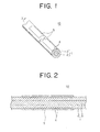
- the method for manufacturing the colored electric wire according to the first embodiment of the present invention forms recesses 4 on a portion of an outer surface of the electric wire using a shot-blasting unit 6 illustrated in FIG. 4 , and then a coloring unit (not shown) applies a coloring material 5 to the portion of the outer surface having the recesses, and thus a colored electric wire 10 illustrated in FIGS. 1 and 2 is obtained.
- the colored electric wire 10 is used as a constituent part of an automotive wiring harness to supply electric power to and transmit control signals and/or other information between electronic or electrical components.
- the electric wire 1 of the colored electric wire 10 has an electrically-conductive core wire 2 which is a stranded lead wire, and an insulating jacket 3 that covers the core wire 2.
- the electric wire that is not colored by a coloring process is simply called “electric wire 1", while the electric wire 1 that has been colored is referred to as “colored electric wire 10.”
- the jacket 3 is made of a synthetic resin such as polyvinylchloride (PVC).
- the synthetic resin of the jacket 3 is colored with a desired color obtained by using one or more coloring materials.
- the synthetic resin of the jacket 3 may be colorless or uncolored without use of any coloring materials.
- a color of the jacket 3 that is not colored with the coloring material is called "ground color" ("ji-iro" in Japanese).
- the outer surface of the electric wire 1 is also referred to as the outer surface of the jacket 3 or the outer surface of the colored electric wire 10 where appropriate in this specification.
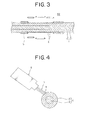
- recesses 4 (which may be small holes, dents, pits, dimples or indentations, for example) are formed on a portion of the outer surface of the jacket 3 by a shot-blasting unit 6 which will be explained later.
- irregularity a predetermined degree of roughness or asperity
- the recesses 4 are formed on the outer surface of the jacket 3 radially inwardly toward the center of the core wire 2. A depth of the recess 4 is restrained such that the recess 4 does not penetrating the jacket 3 so as not to reach the core wire 2.
- portion of the outer surface denotes a specific section that is to be colored.
- the portion of the outer surface of the jacket 3, on which the recesses 4 are formed is the specific section of the outer surface that is to be colored with a coloring material 5.
- the coloring material 5 has a color different from the ground color of the jacket 3.
- the coloring material 5 is used to provide a colored mark on the outer surface of the jacket 3.
- the mark is in a shape of a line extending in a longitudinal direction of the electric wire 1.
- the coloring material 5 may be made of a pigment and a solvent in which the pigment is dispersed. It is preferable that the coloring material 5 has affinity for the synthetic resin that the jacket 3 is made of.
- the colored electric wire 1 is obtained by forming recesses 4 on the portion of the outer surface of the electric wire 1, and then applying the coloring material to the portion on which the recesses 4 have been formed.
- An anchor effect produced by the coloring material 5 retained in the recesses 4 ensures more reliable adhesiveness of the coloring material 5 to the outer surface, thus preventing the coloring material 5 from coming off the electric wire 1. Also, even when the coloring material 5 is lost due to friction of the outer surface, as can be seen in FIG. 3 , the coloring material 5 is effectively kept in the recesses 4, so that the colored electric wire 10 can be identified with ease and accuracy.
- a colored-electric-wire manufacturing device directed to implementing the method for manufacturing the colored electric wire 10 has the shot-blasting unit 6 illustrated in FIG. 4 , a coloring unit (not shown) that blows and distributes the coloring material 5 against the outer surface of the electric wire 1, and a wire supply unit (not shown) that feeds and moves the electric wire 1 in the longitudinal direction of the electric wire 1.
- the shot-blasting unit 6 is a known device that has a centrifugal fan that blows numerous abrasive grains 7 (a glass bead or a metallic particle, for example) against an outer surface of a workpiece.
- the electric wire 1 is fed and moved by the wire supply unit, and the shot-blasting unit 6 applies the abrasive grains to the portion of the outer surface of the electric wire 1 to be colored.
- the recesses 4 are continuously formed on the outer surface of the electric wire 1 so as to impart the irregularity thereupon.
- the electric wire 1 whose outer surface has the recesses 4 formed by the shot-blasting unit 6, is placed underneath the coloring unit by the wire supply unit, and then the coloring unit applies the coloring material 5 to the outer surface of the electric wire 1.
- the colored electric wire 10 obtained by the above shot-blasting and the subsequent coloring processes is the one illustrated in FIG. 1 .
- the shot-blasting unit 6 is used to form the recesses 4 on the outer surface of the electric wire 1.
- the electric wire 1 is continuously fed without stoppage of the wire supply unit, and the recesses 4 can be continuously formed on the outer surface.
- manufacturability of the colored electric wire 10 will be improved.
- the method for manufacturing the colored electric wire according to the present invention involves another approach to providing the irregularity of surface.
- the following describes the second embodiment of the present invention with reference to FIGS. 5 and 6 .
- FIGS. 5 and 6 are dedicated to the second embodiment, the reference signs (i.e., 1, 2, and 3) in the first embodiment also appear in FIGS. 5 and 6 to indicate the same features as in the first embodiment. Accordingly, the description pertaining to the subj ect matter common to both embodiments will not be reiterated in the following paragraphs.
- the recesses 4 are formed on the outer surface of the electric wire 1 using a hole-making unit 8. After that, the coloring material 5 is applied to the outer surface on which the recesses 4 have been formed using a coloring unit (not shown). Thus, the colored electric wire 10 illustrated in FIGS. 1 and 2 can be obtained.
- the hole-making unit 8 has hole-making members 81 having needles 80 like a pinholder used in Ikebana (Japanese flower arrangement), and a moving unit (not shown) that moves the hole-making members 81 close to and away from the electric wire 1, i.e., radially inwardly and outwardly of the electric wire 1.
- the hole-making unit 8 according to the second embodiment has the four hole-making members 81 that surround the electric wire 1.
- the hole-making unit 8 controlled by the moving unit makes the hole-making members 81 approach the electric wire 1 until the outer surface of the electric wire 1 is pricked with the needles 80 and the predetermined degree of irregularity or roughness of the outer surface is imparted by the recesses 4 around the entire periphery of the electric wire 1 (see FIG. 6 ).
- the outer surface of the electric wire 1 is pricked with the needles 80 to impart the irregularity of the outer surface, i.e., the plurality of the recesses 4. Accordingly a number and a depth of the recesses 4 can be controlled with precision by the moving unit.
- the shot-blasting unit 6 and the hole-making unit 8 are used to form the recesses on the outer surface of the electric wire 1.
- an operator may manually press the hole-making members 81 onto the electric wire 1 to provide the irregularity, or more specifically, the recesses 4 on the outer surface of the electric wire 1.
Landscapes
- Engineering & Computer Science (AREA)
- Manufacturing & Machinery (AREA)
- Manufacturing Of Electric Cables (AREA)
- Polishing Bodies And Polishing Tools (AREA)
Applications Claiming Priority (1)
| Application Number | Priority Date | Filing Date | Title |
|---|---|---|---|
| JP2007229684A JP5198817B2 (ja) | 2007-09-05 | 2007-09-05 | 着色電線の製造方法 |
Publications (3)
| Publication Number | Publication Date |
|---|---|
| EP2034492A2 true EP2034492A2 (de) | 2009-03-11 |
| EP2034492A3 EP2034492A3 (de) | 2010-06-16 |
| EP2034492B1 EP2034492B1 (de) | 2011-09-28 |
Family
ID=40091430
Family Applications (1)
| Application Number | Title | Priority Date | Filing Date |
|---|---|---|---|
| EP08160874A Ceased EP2034492B1 (de) | 2007-09-05 | 2008-07-22 | Verfahren zur Herstellung eines farbigen elektrischen Drahtes |
Country Status (3)
| Country | Link |
|---|---|
| US (1) | US8586135B2 (de) |
| EP (1) | EP2034492B1 (de) |
| JP (1) | JP5198817B2 (de) |
Cited By (1)
| Publication number | Priority date | Publication date | Assignee | Title |
|---|---|---|---|---|
| WO2015009672A1 (en) * | 2013-07-19 | 2015-01-22 | Corning Optical Communications LLC | Optical fiber cable with print protective outer surface profile |
Families Citing this family (7)
| Publication number | Priority date | Publication date | Assignee | Title |
|---|---|---|---|---|
| GB201110508D0 (en) * | 2011-06-22 | 2011-08-03 | Smartwater Technology Ltd | A method for applying a marker to an electrical cable during manufacture |
| JP5847488B2 (ja) * | 2011-08-19 | 2016-01-20 | 株式会社小寺電子製作所 | 着色装置 |
| CA2959021C (en) * | 2014-08-22 | 2021-01-26 | Corning Optical Communications LLC | Optical fiber cable with print protective outer surface profile |
| US9718080B1 (en) | 2016-05-06 | 2017-08-01 | RADCO Infusion Technologies, LLC | Linear substrate infusion compartment |
| EP3452232A1 (de) | 2016-05-06 | 2019-03-13 | Radco Infusion Technologies, LLC | Kontinuierliche lineare substratinfusion |
| JP2020027678A (ja) * | 2018-08-09 | 2020-02-20 | 矢崎エナジーシステム株式会社 | ケーブル、及び、このケーブルの製造方法 |
| US12516471B1 (en) | 2019-03-15 | 2026-01-06 | Southwire Company, Llc | Methods of imparting color to nylon substrates |
Citations (1)
| Publication number | Priority date | Publication date | Assignee | Title |
|---|---|---|---|---|
| JP2006049228A (ja) | 2004-08-09 | 2006-02-16 | Yazaki Corp | 着色ノズル |
Family Cites Families (12)
| Publication number | Priority date | Publication date | Assignee | Title |
|---|---|---|---|---|
| US3229623A (en) * | 1964-06-15 | 1966-01-18 | Gen Cable Corp | Marking metal sheathed cables |
| US3836702A (en) * | 1973-04-03 | 1974-09-17 | Plummer Walter A | Means for sealing and protecting a cable splice |
| JPS59232770A (ja) * | 1983-06-09 | 1984-12-27 | Nishi Nippon Tokushu Kogyosho:Kk | 水中サンドブラスト装置 |
| JPS6038427U (ja) * | 1983-08-23 | 1985-03-16 | 住友電気工業株式会社 | ケ−ブルシ−ス |
| JPS60104308A (ja) * | 1983-11-11 | 1985-06-08 | Hitachi Cable Ltd | 直線マ−ク入りシ−ス押出方法 |
| US4708887A (en) * | 1987-01-20 | 1987-11-24 | Northern Telecom Limited | Method for coloring polymer-insulated wire |
| US4997994A (en) * | 1989-09-01 | 1991-03-05 | At&T Bell Laboratories | Article having marking thereon and methods of making |
| US5444466A (en) * | 1991-03-11 | 1995-08-22 | Electronic Cable Specialists, Inc. | Wire marking system and method |
| JP3085159B2 (ja) * | 1995-10-20 | 2000-09-04 | 住友電装株式会社 | 電線のマーキング方法及び装置 |
| JP4477939B2 (ja) * | 2004-05-31 | 2010-06-09 | 矢崎総業株式会社 | 電線の製造方法及び電線の製造装置 |
| US6906264B1 (en) * | 2004-06-17 | 2005-06-14 | Southwire Company | Color-coded armored cable |
| KR101195682B1 (ko) * | 2005-12-15 | 2012-10-30 | 엘지전자 주식회사 | 휴대용 멀티미디어기기 |
-
2007
- 2007-09-05 JP JP2007229684A patent/JP5198817B2/ja not_active Expired - Fee Related
-
2008
- 2008-07-22 EP EP08160874A patent/EP2034492B1/de not_active Ceased
- 2008-07-24 US US12/219,574 patent/US8586135B2/en not_active Expired - Fee Related
Patent Citations (1)
| Publication number | Priority date | Publication date | Assignee | Title |
|---|---|---|---|---|
| JP2006049228A (ja) | 2004-08-09 | 2006-02-16 | Yazaki Corp | 着色ノズル |
Cited By (3)
| Publication number | Priority date | Publication date | Assignee | Title |
|---|---|---|---|---|
| WO2015009672A1 (en) * | 2013-07-19 | 2015-01-22 | Corning Optical Communications LLC | Optical fiber cable with print protective outer surface profile |
| US9297975B2 (en) | 2013-07-19 | 2016-03-29 | Corning Optical Communications LLC | Optical fiber cable with print protective outer surface profile |
| US9435977B2 (en) | 2013-07-19 | 2016-09-06 | Corning Optical Communications LLC | Optical fiber cable with print protective outer surface profile |
Also Published As
| Publication number | Publication date |
|---|---|
| EP2034492B1 (de) | 2011-09-28 |
| JP2009064601A (ja) | 2009-03-26 |
| EP2034492A3 (de) | 2010-06-16 |
| JP5198817B2 (ja) | 2013-05-15 |
| US20090056852A1 (en) | 2009-03-05 |
| US8586135B2 (en) | 2013-11-19 |
Similar Documents
| Publication | Publication Date | Title |
|---|---|---|
| EP2034492B1 (de) | Verfahren zur Herstellung eines farbigen elektrischen Drahtes | |
| EP2647268B1 (de) | Drahthalter und verfahren zum abschliessen von drahtleitern | |
| CN106099620B (zh) | 线缆加工装置和用于从被屏蔽的多芯圆线缆上去除屏蔽薄膜的方法 | |
| US9027505B2 (en) | Apparatus and method for coloring electrical wire | |
| CN109964286B (zh) | 线束以及线束的制造方法 | |
| US8646397B2 (en) | Method and apparatus for producing machine stitched flat wiring harness | |
| WO2008102490A1 (en) | Electrical cable, apparatus and method of coloring and manufacturing same | |
| EP1388868A2 (de) | Beschichtungsverfahren und -apparat für elektrische Kabel | |
| US9312616B2 (en) | Plug connection having a guide element optimized for preventing shavings | |
| CN100354983C (zh) | 电线及电线着色装置 | |
| EP3106840B1 (de) | Elektrischer sensor mit abschirmhülle | |
| DE102015007550B4 (de) | Elektrischer Sensor | |
| CN113224691B (zh) | 编织物切割单元和编织物切割方法 | |
| KR20020052207A (ko) | 전기 기계용 아마추어 | |
| US20060118323A1 (en) | Wire harness with concentric code identifier | |
| JP5529953B2 (ja) | 着色電線の製造方法 | |
| US6782607B2 (en) | Wire positioning device apparatus, methods and articles of manufacture | |
| CN212783907U (zh) | 一种多同轴接触件导向工具 | |
| JPH05135843A (ja) | 端子付き絶縁コードの製造方法および端子付き絶縁コードならびに端子付き絶縁コードに用いる端子台 | |
| JP5028030B2 (ja) | 電線着色装置 | |
| JPH0973820A (ja) | 電気ケーブル及びその配線方法 | |
| JP2003303524A (ja) | 電線の製造方法 | |
| US20100139949A1 (en) | Splice wire holder | |
| JP3292743B2 (ja) | フラットケーブル | |
| JP2006113441A (ja) | 線状体及びその製造方法 |
Legal Events
| Date | Code | Title | Description |
|---|---|---|---|
| PUAI | Public reference made under article 153(3) epc to a published international application that has entered the european phase |
Free format text: ORIGINAL CODE: 0009012 |
|
| AK | Designated contracting states |
Kind code of ref document: A2 Designated state(s): AT BE BG CH CY CZ DE DK EE ES FI FR GB GR HR HU IE IS IT LI LT LU LV MC MT NL NO PL PT RO SE SI SK TR |
|
| AX | Request for extension of the european patent |
Extension state: AL BA MK RS |
|
| PUAL | Search report despatched |
Free format text: ORIGINAL CODE: 0009013 |
|
| AK | Designated contracting states |
Kind code of ref document: A3 Designated state(s): AT BE BG CH CY CZ DE DK EE ES FI FR GB GR HR HU IE IS IT LI LT LU LV MC MT NL NO PL PT RO SE SI SK TR |
|
| AX | Request for extension of the european patent |
Extension state: AL BA MK RS |
|
| 17P | Request for examination filed |
Effective date: 20101214 |
|
| AKX | Designation fees paid |
Designated state(s): DE FR GB |
|
| GRAP | Despatch of communication of intention to grant a patent |
Free format text: ORIGINAL CODE: EPIDOSNIGR1 |
|
| RIC1 | Information provided on ipc code assigned before grant |
Ipc: H01B 13/34 20060101AFI20110323BHEP |
|
| GRAS | Grant fee paid |
Free format text: ORIGINAL CODE: EPIDOSNIGR3 |
|
| GRAA | (expected) grant |
Free format text: ORIGINAL CODE: 0009210 |
|
| AK | Designated contracting states |
Kind code of ref document: B1 Designated state(s): DE FR GB |
|
| REG | Reference to a national code |
Ref country code: GB Ref legal event code: FG4D |
|
| REG | Reference to a national code |
Ref country code: DE Ref legal event code: R096 Ref document number: 602008010101 Country of ref document: DE Effective date: 20111124 |
|
| PLBE | No opposition filed within time limit |
Free format text: ORIGINAL CODE: 0009261 |
|
| STAA | Information on the status of an ep patent application or granted ep patent |
Free format text: STATUS: NO OPPOSITION FILED WITHIN TIME LIMIT |
|
| 26N | No opposition filed |
Effective date: 20120629 |
|
| REG | Reference to a national code |
Ref country code: DE Ref legal event code: R097 Ref document number: 602008010101 Country of ref document: DE Effective date: 20120629 |
|
| REG | Reference to a national code |
Ref country code: FR Ref legal event code: PLFP Year of fee payment: 8 |
|
| REG | Reference to a national code |
Ref country code: FR Ref legal event code: PLFP Year of fee payment: 9 |
|
| REG | Reference to a national code |
Ref country code: FR Ref legal event code: PLFP Year of fee payment: 10 |
|
| REG | Reference to a national code |
Ref country code: FR Ref legal event code: PLFP Year of fee payment: 11 |
|
| PGFP | Annual fee paid to national office [announced via postgrant information from national office to epo] |
Ref country code: FR Payment date: 20200611 Year of fee payment: 13 |
|
| PGFP | Annual fee paid to national office [announced via postgrant information from national office to epo] |
Ref country code: GB Payment date: 20200716 Year of fee payment: 13 Ref country code: DE Payment date: 20200707 Year of fee payment: 13 |
|
| REG | Reference to a national code |
Ref country code: DE Ref legal event code: R119 Ref document number: 602008010101 Country of ref document: DE |
|
| GBPC | Gb: european patent ceased through non-payment of renewal fee |
Effective date: 20210722 |
|
| PG25 | Lapsed in a contracting state [announced via postgrant information from national office to epo] |
Ref country code: GB Free format text: LAPSE BECAUSE OF NON-PAYMENT OF DUE FEES Effective date: 20210722 Ref country code: DE Free format text: LAPSE BECAUSE OF NON-PAYMENT OF DUE FEES Effective date: 20220201 |
|
| PG25 | Lapsed in a contracting state [announced via postgrant information from national office to epo] |
Ref country code: FR Free format text: LAPSE BECAUSE OF NON-PAYMENT OF DUE FEES Effective date: 20210731 |