EP2034492A2 - Method for manufacturing a colored electric wire - Google Patents
Method for manufacturing a colored electric wire Download PDFInfo
- Publication number
- EP2034492A2 EP2034492A2 EP08160874A EP08160874A EP2034492A2 EP 2034492 A2 EP2034492 A2 EP 2034492A2 EP 08160874 A EP08160874 A EP 08160874A EP 08160874 A EP08160874 A EP 08160874A EP 2034492 A2 EP2034492 A2 EP 2034492A2
- Authority
- EP
- European Patent Office
- Prior art keywords
- electric wire
- colored
- recesses
- coloring material
- manufacturing
- Prior art date
- Legal status (The legal status is an assumption and is not a legal conclusion. Google has not performed a legal analysis and makes no representation as to the accuracy of the status listed.)
- Granted
Links
Images

Classifications
-
- H—ELECTRICITY
- H01—ELECTRIC ELEMENTS
- H01B—CABLES; CONDUCTORS; INSULATORS; SELECTION OF MATERIALS FOR THEIR CONDUCTIVE, INSULATING OR DIELECTRIC PROPERTIES
- H01B13/00—Apparatus or processes specially adapted for manufacturing conductors or cables
- H01B13/34—Apparatus or processes specially adapted for manufacturing conductors or cables for marking conductors or cables
- H01B13/345—Apparatus or processes specially adapted for manufacturing conductors or cables for marking conductors or cables by spraying, ejecting or dispensing marking fluid
Definitions
- the present invention relates to a method for manufacturing a colored electric wire, and particularly to a method for manufacturing an electric wire having an outer surface a portion of which is colored.
- An automotive wiring harness has numerous electric wires that serve to supply electric power to and transmit control signals and other operational information between electronic and electrical components of an automobile.
- the electric wire is made of an electrically conductive core wire covered by an insulating jacket, with a connector attached to an end of the core wire.
- the electric wire is obtained by first cutting the electric wire in a predetermined length, attaching a terminal fitting to the end of the electric wire, inserting the terminal fitting into a housing of the connector, and then connecting the connector to a connector of the electronic or electrical component so as to deliver the electric power to and/or exchange control information between the components.
- the wiring harness has to integrate an increasing number of the electric wires, and it is of importance to color an outer surface of the electric wires with coloring materials applied to a portion of the outer surface of the electric wire so that the electric wires that have different functions can be distinguished from each other when assembling the wiring harness or for maintenance purpose (for example, refer to the Japanese Patent Application Laid-Open Publication No. 2006-49228 ).
- an object of the present invention is to provide a method for manufacturing a colored electric wire that ensures improved adhesiveness of a coloring material applied to and retained on an outer surface of the electric wire.
- the portion of the outer surface of the electric wire is colored by applying the coloring material to the recesses that has been formed on the portion of the outer surface
- adhesiveness of the coloring material applied to and retained on the portion of the outer surface can be enhanced by virtue of an anchor effect, thus protecting the coloring material against coming off the outer surface of the electric wire.
- the coloring material retained in the recesses facilitates the identification of the types of the colored electric wires even when the coloring material has come off the electric wire due to the outer surface being rubbed.
- the recesses are provided by blowing abrasive grains against the portion of the outer surface.
- the recesses may be provided by pricking the portion of the outer surface with a needle. Incorporation of this alternative feature allows accurate control of properties of the recesses such as a depth and a number of the recesses.
- a method for manufacturing a colored electric wire according to a first embodiment of the present invention is described in detail with reference to FIGS. 1 to 4 .
- the method for manufacturing the colored electric wire according to the first embodiment of the present invention forms recesses 4 on a portion of an outer surface of the electric wire using a shot-blasting unit 6 illustrated in FIG. 4 , and then a coloring unit (not shown) applies a coloring material 5 to the portion of the outer surface having the recesses, and thus a colored electric wire 10 illustrated in FIGS. 1 and 2 is obtained.
- the colored electric wire 10 is used as a constituent part of an automotive wiring harness to supply electric power to and transmit control signals and/or other information between electronic or electrical components.
- the electric wire 1 of the colored electric wire 10 has an electrically-conductive core wire 2 which is a stranded lead wire, and an insulating jacket 3 that covers the core wire 2.
- the electric wire that is not colored by a coloring process is simply called “electric wire 1", while the electric wire 1 that has been colored is referred to as “colored electric wire 10.”
- the jacket 3 is made of a synthetic resin such as polyvinylchloride (PVC).
- the synthetic resin of the jacket 3 is colored with a desired color obtained by using one or more coloring materials.
- the synthetic resin of the jacket 3 may be colorless or uncolored without use of any coloring materials.
- a color of the jacket 3 that is not colored with the coloring material is called "ground color" ("ji-iro" in Japanese).
- the outer surface of the electric wire 1 is also referred to as the outer surface of the jacket 3 or the outer surface of the colored electric wire 10 where appropriate in this specification.
- recesses 4 (which may be small holes, dents, pits, dimples or indentations, for example) are formed on a portion of the outer surface of the jacket 3 by a shot-blasting unit 6 which will be explained later.
- irregularity a predetermined degree of roughness or asperity
- the recesses 4 are formed on the outer surface of the jacket 3 radially inwardly toward the center of the core wire 2. A depth of the recess 4 is restrained such that the recess 4 does not penetrating the jacket 3 so as not to reach the core wire 2.
- portion of the outer surface denotes a specific section that is to be colored.
- the portion of the outer surface of the jacket 3, on which the recesses 4 are formed is the specific section of the outer surface that is to be colored with a coloring material 5.
- the coloring material 5 has a color different from the ground color of the jacket 3.
- the coloring material 5 is used to provide a colored mark on the outer surface of the jacket 3.
- the mark is in a shape of a line extending in a longitudinal direction of the electric wire 1.
- the coloring material 5 may be made of a pigment and a solvent in which the pigment is dispersed. It is preferable that the coloring material 5 has affinity for the synthetic resin that the jacket 3 is made of.
- the colored electric wire 1 is obtained by forming recesses 4 on the portion of the outer surface of the electric wire 1, and then applying the coloring material to the portion on which the recesses 4 have been formed.
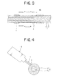
- An anchor effect produced by the coloring material 5 retained in the recesses 4 ensures more reliable adhesiveness of the coloring material 5 to the outer surface, thus preventing the coloring material 5 from coming off the electric wire 1. Also, even when the coloring material 5 is lost due to friction of the outer surface, as can be seen in FIG. 3 , the coloring material 5 is effectively kept in the recesses 4, so that the colored electric wire 10 can be identified with ease and accuracy.
- a colored-electric-wire manufacturing device directed to implementing the method for manufacturing the colored electric wire 10 has the shot-blasting unit 6 illustrated in FIG. 4 , a coloring unit (not shown) that blows and distributes the coloring material 5 against the outer surface of the electric wire 1, and a wire supply unit (not shown) that feeds and moves the electric wire 1 in the longitudinal direction of the electric wire 1.
- the shot-blasting unit 6 is a known device that has a centrifugal fan that blows numerous abrasive grains 7 (a glass bead or a metallic particle, for example) against an outer surface of a workpiece.
- the electric wire 1 is fed and moved by the wire supply unit, and the shot-blasting unit 6 applies the abrasive grains to the portion of the outer surface of the electric wire 1 to be colored.
- the recesses 4 are continuously formed on the outer surface of the electric wire 1 so as to impart the irregularity thereupon.
- the electric wire 1 whose outer surface has the recesses 4 formed by the shot-blasting unit 6, is placed underneath the coloring unit by the wire supply unit, and then the coloring unit applies the coloring material 5 to the outer surface of the electric wire 1.
- the colored electric wire 10 obtained by the above shot-blasting and the subsequent coloring processes is the one illustrated in FIG. 1 .
- the shot-blasting unit 6 is used to form the recesses 4 on the outer surface of the electric wire 1.
- the electric wire 1 is continuously fed without stoppage of the wire supply unit, and the recesses 4 can be continuously formed on the outer surface.
- manufacturability of the colored electric wire 10 will be improved.
- the method for manufacturing the colored electric wire according to the present invention involves another approach to providing the irregularity of surface.
- the following describes the second embodiment of the present invention with reference to FIGS. 5 and 6 .
- FIGS. 5 and 6 are dedicated to the second embodiment, the reference signs (i.e., 1, 2, and 3) in the first embodiment also appear in FIGS. 5 and 6 to indicate the same features as in the first embodiment. Accordingly, the description pertaining to the subj ect matter common to both embodiments will not be reiterated in the following paragraphs.
- the recesses 4 are formed on the outer surface of the electric wire 1 using a hole-making unit 8. After that, the coloring material 5 is applied to the outer surface on which the recesses 4 have been formed using a coloring unit (not shown). Thus, the colored electric wire 10 illustrated in FIGS. 1 and 2 can be obtained.
- the hole-making unit 8 has hole-making members 81 having needles 80 like a pinholder used in Ikebana (Japanese flower arrangement), and a moving unit (not shown) that moves the hole-making members 81 close to and away from the electric wire 1, i.e., radially inwardly and outwardly of the electric wire 1.
- the hole-making unit 8 according to the second embodiment has the four hole-making members 81 that surround the electric wire 1.
- the hole-making unit 8 controlled by the moving unit makes the hole-making members 81 approach the electric wire 1 until the outer surface of the electric wire 1 is pricked with the needles 80 and the predetermined degree of irregularity or roughness of the outer surface is imparted by the recesses 4 around the entire periphery of the electric wire 1 (see FIG. 6 ).
- the outer surface of the electric wire 1 is pricked with the needles 80 to impart the irregularity of the outer surface, i.e., the plurality of the recesses 4. Accordingly a number and a depth of the recesses 4 can be controlled with precision by the moving unit.
- the shot-blasting unit 6 and the hole-making unit 8 are used to form the recesses on the outer surface of the electric wire 1.
- an operator may manually press the hole-making members 81 onto the electric wire 1 to provide the irregularity, or more specifically, the recesses 4 on the outer surface of the electric wire 1.
Abstract
Description
- The present invention relates to a method for manufacturing a colored electric wire, and particularly to a method for manufacturing an electric wire having an outer surface a portion of which is colored.
- An automotive wiring harness has numerous electric wires that serve to supply electric power to and transmit control signals and other operational information between electronic and electrical components of an automobile. The electric wire is made of an electrically conductive core wire covered by an insulating jacket, with a connector attached to an end of the core wire.
- The electric wire is obtained by first cutting the electric wire in a predetermined length, attaching a terminal fitting to the end of the electric wire, inserting the terminal fitting into a housing of the connector, and then connecting the connector to a connector of the electronic or electrical component so as to deliver the electric power to and/or exchange control information between the components.
- As the automobile incorporates an increasing number of and various types of the electronic and electrical components, the wiring harness has to integrate an increasing number of the electric wires, and it is of importance to color an outer surface of the electric wires with coloring materials applied to a portion of the outer surface of the electric wire so that the electric wires that have different functions can be distinguished from each other when assembling the wiring harness or for maintenance purpose (for example, refer to the Japanese Patent Application Laid-Open Publication No.
2006-49228 - However, a drawback of the electric wire that has undergone a coloring process is that the coloring material comes off the electric wire due to bending or friction of the electric wire. This drawback causes another drawback that the numerous electric wires are hard to identify during maintenance and/or possibly manufacturing of the wiring harness.
- In view of the above identified problems, an object of the present invention is to provide a method for manufacturing a colored electric wire that ensures improved adhesiveness of a coloring material applied to and retained on an outer surface of the electric wire.
- It is therefore a feature of an embodiment of the present invention to provide a method for manufacturing a colored electric wire having the outer surface a portion of which is colored, which includes the successive steps of forming recesses upon the portion of the outer surface, and then applying the coloring material to the portion of the outer surface on which the recesses has been formed, thus obtaining the colored electric wire.
- According to the method of the present invention, since the portion of the outer surface of the electric wire is colored by applying the coloring material to the recesses that has been formed on the portion of the outer surface, adhesiveness of the coloring material applied to and retained on the portion of the outer surface can be enhanced by virtue of an anchor effect, thus protecting the coloring material against coming off the outer surface of the electric wire. The coloring material retained in the recesses facilitates the identification of the types of the colored electric wires even when the coloring material has come off the electric wire due to the outer surface being rubbed.
- Preferably, the recesses are provided by blowing abrasive grains against the portion of the outer surface. By virtue of this feature, it is possible to continuously feed the electric wire and form the recesses without stoppage or interruption of operation, and manufacturability of the colored electric wire will be improved.
- As an alternative to application of the abrasive grains, the recesses may be provided by pricking the portion of the outer surface with a needle. Incorporation of this alternative feature allows accurate control of properties of the recesses such as a depth and a number of the recesses.
- These and other objects, features, and advantages of the present invention will become more apparent upon reading of the following detailed description along with the accompanied drawings, in which:
-
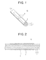
FIG. 1 is a perspective view of a colored electric wire manufactured according to the method of the present invention. -
FIG. 2 is a cross-sectional view taken along the line X-X ofFIG. 1 . -
FIG. 3 is a cross-sectional view of the colored electric wire ofFIG. 2 , where the coloring material came off the colored electric wire. -
FIG. 4 illustrates the method for manufacturing the colored electric wire ofFIG. 1 according to a first embodiment of the present invention. -
FIG. 5 illustrates the method for manufacturing the colored electric wire ofFIG. 1 according to a second embodiment of the present invention. -
FIG. 6 illustrates the method for manufacturing the colored electric wire ofFIG. 1 according to the second embodiment of the present invention. - A method for manufacturing a colored electric wire according to a first embodiment of the present invention is described in detail with reference to
FIGS. 1 to 4 . - The method for manufacturing the colored electric wire according to the first embodiment of the present invention forms
recesses 4 on a portion of an outer surface of the electric wire using a shot-blasting unit 6 illustrated inFIG. 4 , and then a coloring unit (not shown) applies acoloring material 5 to the portion of the outer surface having the recesses, and thus a coloredelectric wire 10 illustrated inFIGS. 1 and 2 is obtained. Also, the coloredelectric wire 10 is used as a constituent part of an automotive wiring harness to supply electric power to and transmit control signals and/or other information between electronic or electrical components. - Referring to
FIG. 1 illustrating a perspective view of the colored electric wire manufactured according to the method of the present invention, theelectric wire 1 of the coloredelectric wire 10 has an electrically-conductive core wire 2 which is a stranded lead wire, and aninsulating jacket 3 that covers thecore wire 2. In this specification, the electric wire that is not colored by a coloring process is simply called "electric wire 1", while theelectric wire 1 that has been colored is referred to as "coloredelectric wire 10." - The
jacket 3 is made of a synthetic resin such as polyvinylchloride (PVC). The synthetic resin of thejacket 3 is colored with a desired color obtained by using one or more coloring materials. Also, the synthetic resin of thejacket 3 may be colorless or uncolored without use of any coloring materials. In this specification, a color of thejacket 3 that is not colored with the coloring material is called "ground color" ("ji-iro" in Japanese). Note that, for the sake of explanation, the outer surface of theelectric wire 1 is also referred to as the outer surface of thejacket 3 or the outer surface of the coloredelectric wire 10 where appropriate in this specification. - Referring to
FIG. 2 showing a cross-sectional view taken along the line X-X ofFIG. 1 , recesses 4 (which may be small holes, dents, pits, dimples or indentations, for example) are formed on a portion of the outer surface of thejacket 3 by a shot-blasting unit 6 which will be explained later. Thus, irregularity (a predetermined degree of roughness or asperity) of surface due to existence of the recesses 4is imparted to the portion of the outer surface of thejacket 3. Also, therecesses 4 are formed on the outer surface of thejacket 3 radially inwardly toward the center of thecore wire 2. A depth of therecess 4 is restrained such that therecess 4 does not penetrating thejacket 3 so as not to reach thecore wire 2. - Note that the term "portion of the outer surface" denotes a specific section that is to be colored. To be more specific, the portion of the outer surface of the
jacket 3, on which therecesses 4 are formed, is the specific section of the outer surface that is to be colored with acoloring material 5. Thecoloring material 5 has a color different from the ground color of thejacket 3. Thecoloring material 5 is used to provide a colored mark on the outer surface of thejacket 3. The mark is in a shape of a line extending in a longitudinal direction of theelectric wire 1. Thecoloring material 5 may be made of a pigment and a solvent in which the pigment is dispersed. It is preferable that thecoloring material 5 has affinity for the synthetic resin that thejacket 3 is made of. - According to the present invention, the colored
electric wire 1 is obtained by formingrecesses 4 on the portion of the outer surface of theelectric wire 1, and then applying the coloring material to the portion on which therecesses 4 have been formed. An anchor effect produced by thecoloring material 5 retained in therecesses 4 ensures more reliable adhesiveness of thecoloring material 5 to the outer surface, thus preventing thecoloring material 5 from coming off theelectric wire 1. Also, even when thecoloring material 5 is lost due to friction of the outer surface, as can be seen inFIG. 3 , thecoloring material 5 is effectively kept in therecesses 4, so that the coloredelectric wire 10 can be identified with ease and accuracy. - Also, a colored-electric-wire manufacturing device directed to implementing the method for manufacturing the colored
electric wire 10 has the shot-blasting unit 6 illustrated inFIG. 4 , a coloring unit (not shown) that blows and distributes thecoloring material 5 against the outer surface of theelectric wire 1, and a wire supply unit (not shown) that feeds and moves theelectric wire 1 in the longitudinal direction of theelectric wire 1. - Referring to
FIG. 4 , the shot-blasting unit 6 is a known device that has a centrifugal fan that blows numerous abrasive grains 7 (a glass bead or a metallic particle, for example) against an outer surface of a workpiece. Theelectric wire 1 is fed and moved by the wire supply unit, and the shot-blasting unit 6 applies the abrasive grains to the portion of the outer surface of theelectric wire 1 to be colored. Therecesses 4 are continuously formed on the outer surface of theelectric wire 1 so as to impart the irregularity thereupon. - After that, the
electric wire 1, whose outer surface has therecesses 4 formed by the shot-blasting unit 6, is placed underneath the coloring unit by the wire supply unit, and then the coloring unit applies thecoloring material 5 to the outer surface of theelectric wire 1. Needless to say, the coloredelectric wire 10 obtained by the above shot-blasting and the subsequent coloring processes is the one illustrated inFIG. 1 . - According to the present invention, the shot-
blasting unit 6 is used to form therecesses 4 on the outer surface of theelectric wire 1. In addition, theelectric wire 1 is continuously fed without stoppage of the wire supply unit, and therecesses 4 can be continuously formed on the outer surface. Thus, manufacturability of the coloredelectric wire 10 will be improved. - The method for manufacturing the colored electric wire according to the present invention involves another approach to providing the irregularity of surface. The following describes the second embodiment of the present invention with reference to
FIGS. 5 and 6 . AlthoughFIGS. 5 and 6 are dedicated to the second embodiment, the reference signs (i.e., 1, 2, and 3) in the first embodiment also appear inFIGS. 5 and 6 to indicate the same features as in the first embodiment. Accordingly, the description pertaining to the subj ect matter common to both embodiments will not be reiterated in the following paragraphs. - Referring to
FIGS. 5 and 6 , therecesses 4 are formed on the outer surface of theelectric wire 1 using a hole-makingunit 8. After that, thecoloring material 5 is applied to the outer surface on which therecesses 4 have been formed using a coloring unit (not shown). Thus, the coloredelectric wire 10 illustrated inFIGS. 1 and 2 can be obtained. - The hole-making
unit 8 has hole-makingmembers 81 havingneedles 80 like a pinholder used in Ikebana (Japanese flower arrangement), and a moving unit (not shown) that moves the hole-makingmembers 81 close to and away from theelectric wire 1, i.e., radially inwardly and outwardly of theelectric wire 1. As shown inFIG. 5 , the hole-makingunit 8 according to the second embodiment has the four hole-makingmembers 81 that surround theelectric wire 1. - Still referring to
FIGS. 5 and 6 , with theelectric wire 1 residing at the center of a circle formed by the four hole-making members 81 (seeFIG. 5 ), the hole-makingunit 8 controlled by the moving unit makes the hole-makingmembers 81 approach theelectric wire 1 until the outer surface of theelectric wire 1 is pricked with theneedles 80 and the predetermined degree of irregularity or roughness of the outer surface is imparted by therecesses 4 around the entire periphery of the electric wire 1 (seeFIG. 6 ). - According to the present invention, the outer surface of the
electric wire 1 is pricked with theneedles 80 to impart the irregularity of the outer surface, i.e., the plurality of therecesses 4. Accordingly a number and a depth of therecesses 4 can be controlled with precision by the moving unit. - Also, in the first and second embodiment of the present invention, the shot-blasting
unit 6 and the hole-makingunit 8 are used to form the recesses on the outer surface of theelectric wire 1. Nevertheless, as an alternative approach, an operator may manually press the hole-makingmembers 81 onto theelectric wire 1 to provide the irregularity, or more specifically, therecesses 4 on the outer surface of theelectric wire 1. - It should be noted that the embodiment described above is illustrated as an example of the possible embodiments of the present invention, and that numerous modifications and variations can be effectuated within the spirit and scope of the present invention.
Claims (3)
- A method for manufacturing a colored electric wire by coloring a portion of an outer surface of an electric wire, comprising the successive steps of:imparting irregularity to the portion of the outer surface and thereafter; applying a coloring material to the portion of the outer surface on which the irregularity has been formed.
- The method as set forth in claim 1, wherein abrasive grains are blown against the portion of the outer surface of the electric wire so as to impart the irregularity thereto.
- The method as set forth in claim 1, wherein the portion of the outer surface is pricked with a needle so as to impart irregularity thereto.
Applications Claiming Priority (1)
| Application Number | Priority Date | Filing Date | Title |
|---|---|---|---|
| JP2007229684A JP5198817B2 (en) | 2007-09-05 | 2007-09-05 | Manufacturing method of colored electric wire |
Publications (3)
| Publication Number | Publication Date |
|---|---|
| EP2034492A2 true EP2034492A2 (en) | 2009-03-11 |
| EP2034492A3 EP2034492A3 (en) | 2010-06-16 |
| EP2034492B1 EP2034492B1 (en) | 2011-09-28 |
Family
ID=40091430
Family Applications (1)
| Application Number | Title | Priority Date | Filing Date |
|---|---|---|---|
| EP08160874A Expired - Fee Related EP2034492B1 (en) | 2007-09-05 | 2008-07-22 | Method for manufacturing a colored electric wire |
Country Status (3)
| Country | Link |
|---|---|
| US (1) | US8586135B2 (en) |
| EP (1) | EP2034492B1 (en) |
| JP (1) | JP5198817B2 (en) |
Cited By (1)
| Publication number | Priority date | Publication date | Assignee | Title |
|---|---|---|---|---|
| WO2015009672A1 (en) * | 2013-07-19 | 2015-01-22 | Corning Optical Communications LLC | Optical fiber cable with print protective outer surface profile |
Families Citing this family (7)
| Publication number | Priority date | Publication date | Assignee | Title |
|---|---|---|---|---|
| US7491995B2 (en) | 2006-04-04 | 2009-02-17 | Micron Technology, Inc. | DRAM with nanofin transistors |
| GB201110508D0 (en) * | 2011-06-22 | 2011-08-03 | Smartwater Technology Ltd | A method for applying a marker to an electrical cable during manufacture |
| JP5847488B2 (en) * | 2011-08-19 | 2016-01-20 | 株式会社小寺電子製作所 | Coloring equipment |
| WO2016028665A1 (en) * | 2014-08-22 | 2016-02-25 | Corning Optical Communications LLC | Optical fiber cable with print protective outer surface profile |
| US9718080B1 (en) | 2016-05-06 | 2017-08-01 | RADCO Infusion Technologies, LLC | Linear substrate infusion compartment |
| US10753039B2 (en) | 2016-05-06 | 2020-08-25 | RADCO Infusion Technologies, LLC | Continuous linear substrate infusion |
| JP2020027678A (en) * | 2018-08-09 | 2020-02-20 | 矢崎エナジーシステム株式会社 | Cable and method for manufacturing cable |
Citations (1)
| Publication number | Priority date | Publication date | Assignee | Title |
|---|---|---|---|---|
| JP2006049228A (en) | 2004-08-09 | 2006-02-16 | Yazaki Corp | Coloring nozzle |
Family Cites Families (12)
| Publication number | Priority date | Publication date | Assignee | Title |
|---|---|---|---|---|
| US3229623A (en) * | 1964-06-15 | 1966-01-18 | Gen Cable Corp | Marking metal sheathed cables |
| US3836702A (en) * | 1973-04-03 | 1974-09-17 | Plummer Walter A | Means for sealing and protecting a cable splice |
| JPS59232770A (en) * | 1983-06-09 | 1984-12-27 | Nishi Nippon Tokushu Kogyosho:Kk | Underwater sandblasting device |
| JPS6038427U (en) * | 1983-08-23 | 1985-03-16 | 住友電気工業株式会社 | cable sheath |
| JPS60104308A (en) * | 1983-11-11 | 1985-06-08 | Hitachi Cable Ltd | Extrusion of sheath with straight line mark |
| US4708887A (en) * | 1987-01-20 | 1987-11-24 | Northern Telecom Limited | Method for coloring polymer-insulated wire |
| US4997994A (en) * | 1989-09-01 | 1991-03-05 | At&T Bell Laboratories | Article having marking thereon and methods of making |
| US5444466A (en) * | 1991-03-11 | 1995-08-22 | Electronic Cable Specialists, Inc. | Wire marking system and method |
| JP3085159B2 (en) * | 1995-10-20 | 2000-09-04 | 住友電装株式会社 | Wire marking method and apparatus |
| JP4477939B2 (en) * | 2004-05-31 | 2010-06-09 | 矢崎総業株式会社 | Electric wire manufacturing method and electric wire manufacturing apparatus |
| US6906264B1 (en) * | 2004-06-17 | 2005-06-14 | Southwire Company | Color-coded armored cable |
| KR101195682B1 (en) * | 2005-12-15 | 2012-10-30 | 엘지전자 주식회사 | Portable multimedia device |
-
2007
- 2007-09-05 JP JP2007229684A patent/JP5198817B2/en not_active Expired - Fee Related
-
2008
- 2008-07-22 EP EP08160874A patent/EP2034492B1/en not_active Expired - Fee Related
- 2008-07-24 US US12/219,574 patent/US8586135B2/en not_active Expired - Fee Related
Patent Citations (1)
| Publication number | Priority date | Publication date | Assignee | Title |
|---|---|---|---|---|
| JP2006049228A (en) | 2004-08-09 | 2006-02-16 | Yazaki Corp | Coloring nozzle |
Cited By (3)
| Publication number | Priority date | Publication date | Assignee | Title |
|---|---|---|---|---|
| WO2015009672A1 (en) * | 2013-07-19 | 2015-01-22 | Corning Optical Communications LLC | Optical fiber cable with print protective outer surface profile |
| US9297975B2 (en) | 2013-07-19 | 2016-03-29 | Corning Optical Communications LLC | Optical fiber cable with print protective outer surface profile |
| US9435977B2 (en) | 2013-07-19 | 2016-09-06 | Corning Optical Communications LLC | Optical fiber cable with print protective outer surface profile |
Also Published As
| Publication number | Publication date |
|---|---|
| US8586135B2 (en) | 2013-11-19 |
| US20090056852A1 (en) | 2009-03-05 |
| EP2034492B1 (en) | 2011-09-28 |
| JP2009064601A (en) | 2009-03-26 |
| JP5198817B2 (en) | 2013-05-15 |
| EP2034492A3 (en) | 2010-06-16 |
Similar Documents
| Publication | Publication Date | Title |
|---|---|---|
| EP2034492B1 (en) | Method for manufacturing a colored electric wire | |
| CN106099620B (en) | Cable processing device and method for removing shielding film from shielded multi-core round cable | |
| EP2647268B1 (en) | Wire holder and method of terminating wire conductors | |
| US9027505B2 (en) | Apparatus and method for coloring electrical wire | |
| US5142105A (en) | Electrical cable and method for manufacturing the same | |
| CN101529534A (en) | Shielded electric wire and method of identifying shielded wire | |
| US8646397B2 (en) | Method and apparatus for producing machine stitched flat wiring harness | |
| EP1388868A2 (en) | Method and Apparatus for Coating Electrical Cable | |
| WO2008102490A1 (en) | Electrical cable, apparatus and method of coloring and manufacturing same | |
| US9312616B2 (en) | Plug connection having a guide element optimized for preventing shavings | |
| CN100354983C (en) | Electric wire and wire coloring apparatus | |
| KR20020052207A (en) | Armature for an electric machine | |
| US20060118323A1 (en) | Wire harness with concentric code identifier | |
| JP5028030B2 (en) | Electric wire coloring device | |
| DE102015007550B4 (en) | Electrical sensor | |
| US6782607B2 (en) | Wire positioning device apparatus, methods and articles of manufacture | |
| CN212783907U (en) | Multi-coaxial contact guiding tool | |
| JPS60151906A (en) | Method of marking identification to coated wire | |
| JP2013110113A (en) | Manufacturing method of colored electric wire | |
| JPH05135843A (en) | Manufacture of insulating cord with terminal, insulating cord with terminal, and terminal block used for insulating cord with terminal | |
| US20100139949A1 (en) | Splice wire holder | |
| JPH0973820A (en) | Electric cable and wiring method therefor | |
| JP2003303524A (en) | Method for manufacturing electric wire | |
| JP3292743B2 (en) | Flat cable | |
| JPH08178130A (en) | Protector, its manufacture and hose with harness |
Legal Events
| Date | Code | Title | Description |
|---|---|---|---|
| PUAI | Public reference made under article 153(3) epc to a published international application that has entered the european phase |
Free format text: ORIGINAL CODE: 0009012 |
|
| AK | Designated contracting states |
Kind code of ref document: A2 Designated state(s): AT BE BG CH CY CZ DE DK EE ES FI FR GB GR HR HU IE IS IT LI LT LU LV MC MT NL NO PL PT RO SE SI SK TR |
|
| AX | Request for extension of the european patent |
Extension state: AL BA MK RS |
|
| PUAL | Search report despatched |
Free format text: ORIGINAL CODE: 0009013 |
|
| AK | Designated contracting states |
Kind code of ref document: A3 Designated state(s): AT BE BG CH CY CZ DE DK EE ES FI FR GB GR HR HU IE IS IT LI LT LU LV MC MT NL NO PL PT RO SE SI SK TR |
|
| AX | Request for extension of the european patent |
Extension state: AL BA MK RS |
|
| 17P | Request for examination filed |
Effective date: 20101214 |
|
| AKX | Designation fees paid |
Designated state(s): DE FR GB |
|
| GRAP | Despatch of communication of intention to grant a patent |
Free format text: ORIGINAL CODE: EPIDOSNIGR1 |
|
| RIC1 | Information provided on ipc code assigned before grant |
Ipc: H01B 13/34 20060101AFI20110323BHEP |
|
| GRAS | Grant fee paid |
Free format text: ORIGINAL CODE: EPIDOSNIGR3 |
|
| GRAA | (expected) grant |
Free format text: ORIGINAL CODE: 0009210 |
|
| AK | Designated contracting states |
Kind code of ref document: B1 Designated state(s): DE FR GB |
|
| REG | Reference to a national code |
Ref country code: GB Ref legal event code: FG4D |
|
| REG | Reference to a national code |
Ref country code: DE Ref legal event code: R096 Ref document number: 602008010101 Country of ref document: DE Effective date: 20111124 |
|
| PLBE | No opposition filed within time limit |
Free format text: ORIGINAL CODE: 0009261 |
|
| STAA | Information on the status of an ep patent application or granted ep patent |
Free format text: STATUS: NO OPPOSITION FILED WITHIN TIME LIMIT |
|
| 26N | No opposition filed |
Effective date: 20120629 |
|
| REG | Reference to a national code |
Ref country code: DE Ref legal event code: R097 Ref document number: 602008010101 Country of ref document: DE Effective date: 20120629 |
|
| REG | Reference to a national code |
Ref country code: FR Ref legal event code: PLFP Year of fee payment: 8 |
|
| REG | Reference to a national code |
Ref country code: FR Ref legal event code: PLFP Year of fee payment: 9 |
|
| REG | Reference to a national code |
Ref country code: FR Ref legal event code: PLFP Year of fee payment: 10 |
|
| REG | Reference to a national code |
Ref country code: FR Ref legal event code: PLFP Year of fee payment: 11 |
|
| PGFP | Annual fee paid to national office [announced via postgrant information from national office to epo] |
Ref country code: FR Payment date: 20200611 Year of fee payment: 13 |
|
| PGFP | Annual fee paid to national office [announced via postgrant information from national office to epo] |
Ref country code: GB Payment date: 20200716 Year of fee payment: 13 Ref country code: DE Payment date: 20200707 Year of fee payment: 13 |
|
| REG | Reference to a national code |
Ref country code: DE Ref legal event code: R119 Ref document number: 602008010101 Country of ref document: DE |
|
| GBPC | Gb: european patent ceased through non-payment of renewal fee |
Effective date: 20210722 |
|
| PG25 | Lapsed in a contracting state [announced via postgrant information from national office to epo] |
Ref country code: GB Free format text: LAPSE BECAUSE OF NON-PAYMENT OF DUE FEES Effective date: 20210722 Ref country code: DE Free format text: LAPSE BECAUSE OF NON-PAYMENT OF DUE FEES Effective date: 20220201 |
|
| PG25 | Lapsed in a contracting state [announced via postgrant information from national office to epo] |
Ref country code: FR Free format text: LAPSE BECAUSE OF NON-PAYMENT OF DUE FEES Effective date: 20210731 |