EP2033930A1 - Fahreinrichtung mit Abweiservorrichtung - Google Patents
Fahreinrichtung mit Abweiservorrichtung Download PDFInfo
- Publication number
- EP2033930A1 EP2033930A1 EP08163736A EP08163736A EP2033930A1 EP 2033930 A1 EP2033930 A1 EP 2033930A1 EP 08163736 A EP08163736 A EP 08163736A EP 08163736 A EP08163736 A EP 08163736A EP 2033930 A1 EP2033930 A1 EP 2033930A1
- Authority
- EP
- European Patent Office
- Prior art keywords
- escalator
- brush
- brush unit
- moving walkway
- profile
- Prior art date
- Legal status (The legal status is an assumption and is not a legal conclusion. Google has not performed a legal analysis and makes no representation as to the accuracy of the status listed.)
- Granted
Links
Images



Classifications
-
- B—PERFORMING OPERATIONS; TRANSPORTING
- B66—HOISTING; LIFTING; HAULING
- B66B—ELEVATORS; ESCALATORS OR MOVING WALKWAYS
- B66B29/00—Safety devices of escalators or moving walkways
- B66B29/02—Safety devices of escalators or moving walkways responsive to, or preventing, jamming by foreign objects
- B66B29/04—Safety devices of escalators or moving walkways responsive to, or preventing, jamming by foreign objects for balustrades or handrails
-
- B—PERFORMING OPERATIONS; TRANSPORTING
- B66—HOISTING; LIFTING; HAULING
- B66B—ELEVATORS; ESCALATORS OR MOVING WALKWAYS
- B66B23/00—Component parts of escalators or moving walkways
- B66B23/22—Balustrades
-
- B—PERFORMING OPERATIONS; TRANSPORTING
- B66—HOISTING; LIFTING; HAULING
- B66B—ELEVATORS; ESCALATORS OR MOVING WALKWAYS
- B66B29/00—Safety devices of escalators or moving walkways
- B66B29/02—Safety devices of escalators or moving walkways responsive to, or preventing, jamming by foreign objects
Definitions
- the invention relates to an escalator or a moving walkway with a step belt with steps or with a pallet band with pallets for the transport of persons and / or objects and held by means of a Balustradensockels balustrade with handrail, wherein arranged on the balustrade pedestal deflector device pinching body parts and / or objects between the existing of the individual stages step band and the balustrade base prevents.
- the deflector device is arranged on a vertical region of the balustrade base and comprises a base profile or deflector profile and a brush unit.
- Driving devices in the sense of the invention which can also be referred to as conveyors, are escalators and moving walks with a plurality of tread units or steps or moving floor pallets, which are connected to an endless conveyor. Users of the driving devices are standing on the steps of the steps or pallets or kiting units.
- a safety device which prevents the pinching between the existing of individual stages step band and the base plates.
- Designed as a deflector safety device consists of a large support profile and different brush elements.
- the arranged on Balustradensockel large carrier profile has a profiled opening on the stage side, in which opening the brush elements can be inserted.
- a brush element consists of a brush body that holds the brushes. The brush body is inserted at the front (from the step side) into the profiled opening of the large, robust carrier profile.
- a wedge element is inserted from a carrier profile end forth between the upper wall of the large support profile and the brush body, wherein the wedge element holds the brush body with a rib.
- EP 1 262 441 assumed as the closest prior art.
- a deflector device is described which is arranged on the or a vertical region of the balustrade base and comprises a deflector profile and a brush unit. During assembly, the brush unit is inserted laterally into the massive, robust, large-area deflector profile.
- a disadvantage of said safety devices is that the assembly is complicated and time-consuming. Other solutions, in turn, are characterized by being easier to assemble. Here, however, is disadvantageous that the simplicity of the installation was bought by a not so robust and stable seat of the safety device.
- a deflection device arranged on the balustrade pedestal of an escalator which consists of a brush carrier with deflector brushes and of a deflector pedestal arranged on the balustrade pedestal.
- the upper edge of the brush holder and the upper edge the Abweisersockels are formed so that the two edges together form a hinge, wherein the edge of the brush holder is hook-shaped in cross-section and the edge of the Abweisersockels in cross-section pear shape and the hook can slide on the bulb.
- the Abweisersockel is fastened to the balustrade base and then the brush holder is inserted at the upper edge of the Abweisersockel and folded with a rotational movement about the hinge axis down.
- the invention as characterized in claim 1 solves the problem of avoiding the disadvantages of the prior art devices and to provide a safety device that is easily and quickly attachable to the base of the escalator and still guarantees outstanding stability and strength.
- An escalator according to the invention or a moving walkway according to the invention comprises a step belt with steps or a pallet conveyor with pallets and a balustrade with handrail held by means of a balustrade pedestal.
- a deflector device is disposed on the balustrade pedestal to prevent trapping between the steps and the balustrade pedestal.
- the deflector device has a deflector profile and a brush unit arranged on the or a vertical region of the balustrade pedestal.
- the deflector profile comprises means for easy or quick vertical joining or joining of the brush unit with the deflector profile.
- Fig. 1 shows an escalator 1, which connects a first floor E1 with a second floor E2.
- the escalator 1 has a stage 5 consisting of step band 4. In the case of a moving walkway this has a pallet band consisting of pallets.
- a handrail 2.2 is arranged on a balustrade 2, which is held at the lower end by means of a balustrade pedestal 3.
- the balustrade base 3 is supported by a support of the escalator 1 and the moving walk.
- Fig. 1 is indicated or drawn that extends a deflector 6 or anti-trap device 6 (also referred to as brush unit or base brush) along the escalator 1. Details and various embodiments of this deflector device 6 or anti-trap device 6 will be described in conjunction with the other figures.
- a deflector 6 or anti-trap device 6 also referred to as brush unit or base brush
- Fig. 2 shows a section along the line AA of Fig. 1
- the upper part of the escalator 1 shows the flow of the step band 4.
- the stages 5 with visible front part 5.1 (also called riser) and tread 5.2 form a staircase.
- the lower part of the escalator 1 shows the return of the step belt 4 and the step 5, wherein the tread surface is directed downwards 5.2.
- Stage rollers arranged on cantilevers are guided by means of guides arranged on a carrier in the usual manner.
- Chain rollers arranged on a step axis are guided by means of further rails or guides arranged on the carrier, wherein each step axis is connected to a drivable conveyor chain.
- the Balustrade base 3 has a vertical base plate 3.1 on the stage side.
- a deflector device 6 or entrapment protection device 6 is provided which prevents the pinching or picking of body parts and / or objects between the existing of the individual stages 5 step belt 4 or pallets consisting of individual pallets and the base plate 3.1.
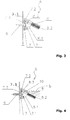
- Fig. 3 shows the section B of Fig. 2 with the inventive deflector device 6 or pinch protection device 6, which comprises a deflector profile or base shell profile or receiving profile or basic profile 7 (also referred to as base profile or brush holder profile) and a brush unit 8 with brushes 8.2.
- the receiving profile 7 or shell profile 7 is virtually a base profile or base profile which is fastened to a vertical surface, preferably to the base plate 3.1.
- the receiving profile 7 or shell profile 7 is connected for example by means of a screw 9 fixed to the base plate 3.1.
- a corresponding, prefabricated screw receptacle of the shell profile 7 or receiving profile 7 accommodates the countersunk head or lens head of the screw 9.
- It may be, for example, a sheet metal screw 9 or drill screw or screw or FDSfliesslochformende- screw or Bohrspitz- screw, which is screwed into the base plate 3.1.
- cage nuts can be arranged on the base plate 3.1 in order to grasp a metric screw 9.
- Self-tapping screws 9 or self-drilling screws or screws or FDS flow-hole forming screws or Bohrspitz screws respectively cage nuts and screws are arranged along the entire step band 4 at certain intervals on the base plate 3.1.
- the receiving profile 7 has fastening means or fastening parts for vertical joining or vertical connection of the brush unit 8.
- the process of vertical joining or vertical joining is in Fig. 6 indicated by a pointing in the direction of arrow.
- the brush unit 8, or a corresponding section thereof is inserted into a lower brush receptacle 7.1 during vertical joining or joining, and then the brush unit 8, or a corresponding section thereof, is hooked into an upper hooking device 7.2 which is attached to the base profile 7 or Shell profile 7 is provided.
- the base profile 7 or shell profile 7 is designed so that forces acting from above on the deflection device 6 or anti-pinch device 6 are introduced essentially into the lower brush holder 7.1 and transferred from there to the base plate 3.1 or transmitted. In this case, the brush unit 8 sits stably and firmly in the lower brush holder 7.1.
- the corresponding fastening means or fastening parts for vertical joining are preferably realized in such a way that a lower brush receptacle 7.1 and an upper hooking device 7.2 as well as corresponding complementary elements on the brush unit 8 are provided on the base or base profile 7.
- the upper hooking device 7.2 is preferably designed for manual and / or abrupt click-in of the brush unit 8. As a result, the assembly of the brush unit 8 on the deflector profile 7 without the use of a tool or special tool done.
- the fastening means or fastening parts for vertical joining a groove 7.4 or 7.4 connecting groove with vertically upwardly projecting nose 7.1 include (see Fig. 6 ).
- This strip or longitudinal bar with nose or spring or spring serves as a lower brush holder and is denoted by the same reference numerals as the nose 7.1.
- a complementary groove 8.4 is provided (see Fig. 6 ) in which the nose 7.1 or spring 7.1 engages or locks.
- the mentioned fastening means or fastening parts can advantageously comprise an upper hooking device 7.2 on the base shell profile or receiving profile or basic profile 7 and a corresponding downwardly pointing hook 8.3 or 8.3 engagement on the brush unit 8.
- This downwardly facing hook 8.3 or engagement 8.3 engages under vertical joining or vertical joining under the upper hooking device 7.2 (e.g., in the form of a barb).
- either the upper hooking device 7.2 and / or the hook 8.3 or the engaging hook 8.3 are / are designed to be partially elastic.
- the receiving profile 7 is preferably made of continuously manufactured material such as steel, aluminum, copper, NIROSTA preferably in the form of a steel extruded profile or drawing profile. But it can also be a steel or aluminum or copper or NIROSTA or plastic profile or injection molding profile as a base profile 7 or basic profile 7 serve.
- bulbs 10 can be integrated into the deflecting device 6 or anti-pinching device 6 according to the invention.
- these bulbs 10 are designed to extend along the Extend conveying direction or conveying length or conveying path of the escalator or the moving walk.
- the user of the driving device can be warned by this measure before the gap or air gap, which is covered by the deflector device 6 or pinch protection device 6.
- the steps or pallets can be illuminated, which helps prevent missteps or wrong steps.
- LEDs or light-emitting diodes which are arranged above, along the anti-pinch protection device 6 or deflection device 6.
- these LEDs sit on a printed circuit board, which can be rigid or flexible.
- This circuit board together with LEDs can be integrated into the body of the brush unit 8, as in Fig. 4 and Fig. 5 shown.
- LEDs semiconductor diodes or, for example, organic light emitting diodes (OLED) can be used.
- Fig. 4 is indicated that the light emitting diode, which serves as a light source 10, radiating in the direction of the brush 8.2 their luminosity or their light L.
- the bulbs 10 can also, as in Fig. 5 shown, emit their light upwards and towards the brush 8.2.
- the electroluminescent film is particularly suitable since it is a so-called Lambert radiator. This means that the luminance of the radiation emanating from the surface is the same from each side. The light radiates from the film almost monochrome and very evenly. That's it for the user of the escalator widely and very visible and recognizable.
- the electroluminescent film can be regarded as a planar luminous means 10 in film form. In a preferred embodiment, it is thinner than one to three millimeters and can be bent like paper. It shines homogeneously without glare and can, with suitable control in a control box 12 (see Fig. 1 ) are insulated.
- the electroluminescent film shows no heat and consumes little energy, this is a huge economic advantage. The lifespan is very high.
- the luminescent films can be delivered in roll form and in lengths of up to 100 meters. As a result, the required length can be easily constructed or accomplished, a prefabrication is advantageous and feasible.
- the luminescent films have the advantage that they are well visible as Lambertstrahler even by smoke or fog, which in case of fire contributes very well to accident prevention and represents a major safety advantage for the user.
- individual shapes can be integrated into the luminous film.
- illuminants 10 are used which emit light in shades of green and blue so as not to dazzle the users of the escalator 1.
- either the entire brush profile 8.1 is made transparent, or at least that part is made transparent, through which the light L is to emerge or can.
- FIG. 7 another embodiment of a brush profile 8.1 is shown in which a lens 10.1 is provided to emit and / or fan out the emergent light L, as desired.
- the cables 11 and light cables 11 and power cables 11 are arranged, as in Fig. 1 indicated and the control can be accommodated in a terminal box 12 and control box 12.
- the junction box 12 or control box 12 is placed or installed in an easily accessible location for service or inspection purposes.
- light sources 10 allows the targeted illumination of the conveyor or the driving device and thus increases the safety of the user.
- the brush unit 8 can be cut to length, that is, in shorter longitudinal sections or sections, or endlessly mounted.
- a particular advantage of the vertically connected or vertically joined base brushes 6 and pinch protection device 6 is the ease of assembly and the better absorption of the loads and forces.
- the brush holder 7.1 and the receiving profile 7 can be made more solid and robust.
- a strong engagement of the brush unit 8 and the brush profile 8.1 is ensured by the barb 7.2.
- a brush unit 8 which was made of plastic, for example by injection molding or extrusion process.
- the brushes 8.2 are preferably inserted into the brush unit 8 integrated, but also a subsequent bristle is possible and conceivable and feasible.
- the invention can be equally applied to escalators and moving walks.
Landscapes
- Escalators And Moving Walkways (AREA)
Abstract
Description
- Die Erfindung betrifft eine Fahrtreppe oder einen Fahrsteig mit einem Stufenband mit Stufen bzw. mit einem Palettenband mit Paletten für den Transport von Personen und/oder Gegenständen und einer mittels eines Balustradensockels gehaltenen Balustrade mit Handlauf, wobei eine am Balustradensockel angeordnete Abweiservorrichtung das Einklemmen von Körperteilen und/oder Gegenständen zwischen dem aus den einzelnen Stufen bestehenden Stufenband und dem Balustradensockel verhindert. Die Abweiservorrichtung ist an einem vertikalen Bereich des Balustradensockels angeordnet und umfasst ein Grundprofil bzw. Abweiserprofil und eine Bürsteneinheit.
- Fahreinrichtungen im Sinne der Erfindung, die auch als Fördereinrichtungen bezeichnet werden können, sind Fahrtreppen und Fahrsteige mit einer Vielzahl von Tritteinheiten bzw. Stufen oder Fahrsteigpaletten, die zu einem Endlosförderer verbunden sind. Benutzer der Fahreinrichtungen stehen auf den Trittflächen der Stufen bzw. Paletten oder Tritteinheiten.
- Ausführungsweise ist ein Spalt bzw. Luftspalt zwischen den Stufen (oder Paletten) und einem vertikalen Bereich der Sockelbleche auf beiden Seiten der Fahreinrichtung vorhanden. Um ein Einklemmen in diesem Spalt bzw. Luftspalt und/oder um das Eindringen von Gegenständen zu verhindern, kommen üblicherweise sogenannte Sockelbürsten zum Einsatz.
- Aus der Patentschrift
US 6 131 719 ist eine Sicherheitseinrichtung bekannt geworden, die das Einklemmen zwischen dem aus einzelnen Stufen bestehenden Stufenband und den Sockelblechen verhindert. Die als Abweiser konzipierte Sicherheitseinrichtung besteht aus einem grossen Trägerprofil und aus verschiedenen Bürstenelementen. Das am Balustradensockel angeordnete grosse Trägerprofil weist stufenseitig eine profilierte Öffnung auf, in welche Öffnung die Bürstenelemente einsetzbar sind. Ein Bürstenelement besteht aus einem Bürstenkörper, der die Bürsten fasst. Der Bürstenkörper wird frontseitig (von der Stufenseite her) in die profilierte Öffnung des grossen, robusten Trägerprofils eingeführt. Nach der Montage des Bürstenelementes wird ein Keilelement vom einen Trägerprofilende her zwischen die obere Wandung des grossen Trägerprofils und den Bürstenkörper eingeschoben, wobei das Keilelement mit einer Rippe den Bürstenkörper festhält. - Weitere Fahreinrichtungen mit entsprechenden Sockelbürsten sind aus den Schriften
EP 1 170 244 ,EP 1 262 441 ,EP 1 188 708 undDE 199 17 796 bekannt, um einige Beispiel zu nennen. - In Folgenden wird von
EP 1 262 441 als nächstliegendem Stand der Technik ausgegangen. In dieser Schrift ist eine Abweiservorrichtung beschrieben, die an dem bzw. einem vertikalen Bereich des Balustradensockels angeordnet ist und ein Abweiserprofil und eine Bürsteneinheit umfasst. Die Bürsteneinheit wird bei der Montage seitlich in das massige, robuste, grossflächige Abweiserprofil eingesetzt. - Nachteilig bei den genannten Sicherheitseinrichtungen ist, dass die Montage aufwendig und zeitintensiv ist. Andere Lösungen wiederum zeichnen sich dadurch aus, dass sie einfacher zu montieren sind. Hier ist aber dann nachteilig, dass die Einfachheit der Montage erkauft wurde durch einen nicht so robusten und stabilen Sitz der Sicherheitseinrichtung.
- Aus der Schrift
US 6 425 472 ist eine am Balustradensockel einer Fahrtreppe angeordnete Abweiservorrichtung bekannt geworden, die aus einem Bürstenträger mit Abweiserbürsten und aus einem am Balustradensockel angeordneten Abweisersockel besteht. Die obere Kante des Bürstenträgers und die obere Kante des Abweisersockels sind so ausgebildet, dass die beiden Kanten zusammen ein Scharnier bilden, wobei die Kante des Bürstenträgers im Querschnitt hakenförmig ist und die Kante des Abweisersockels im Querschnitt birnenförmig ist und der Haken auf der Birne gleiten kann. Zur Montage der Abweiservorrichtung wird der Abweisersockel am Balustradensockel festgemacht und danach der Bürstenträger an der oberen Kante auf den Abweisersockel gesteckt und mit einer Drehbewegung um die Scharnierachse nach unten geklappt. - Hier soll die Erfindung Abhilfe schaffen. Die Erfindung, wie sie in Anspruch 1 gekennzeichnet ist, löst die Aufgabe, die Nachteile der bekannten Einrichtungen zu vermeiden und eine Sicherheitseinrichtung zu schaffen, die einfach und rasch am Sockel der Fahrtreppe anbringbar ist und trotzdem eine herausragende Stabilität und Festigkeit garantiert.
- Eine erfindungsgemässe Fahrtreppe oder ein erfindungsgemässer Fahrsteig umfasst ein Stufenband mit Stufen bzw. ein Palettenband mit Paletten und eine mittels eines Balustradensockels gehaltene Balustrade mit Handlauf. Am Balustradensockel ist eine Abweiservorrichtung angeordnet, um das Einklemmen zwischen den Stufen und dem Balustradensockel zu verhindern. Die Abweiservorrichtung weist ein an dem bzw. einem vertikalen Bereich des Balustradensockels angeordnetes Abweiserprofil und eine Bürsteneinheit auf. Das Abweiserprofil umfasst Mittel zum leichten bzw. einfachen bzw. schnellen vertikalen Fügen oder Verbinden der Bürsteneinheit mit dem Abweiserprofil.
- Die durch die Erfindung erreichten Vorteile sind im Wesentlichen darin zu sehen, dass eine wenig aufwendige Montage der Bürsteneinheiten möglich ist, wobei trotzdem eine hohe Festigkeit bzw. Stabilität bzw. Robustheit erzielt wird. Falls ein Austausch der Bürsteneinheiten notwendig ist, können die alten Bürsteneinheiten mit einfachen Mitteln bzw. Werkzeugen entfernt bzw. getauscht werden und die neuen Bürsteneinheiten können werkzeuglos auf das bestehende Abweiserprofil durch Einschnappen bzw. Einrasten montiert werden. Mit der erfindungsgemässen Einschnappvorrichtung bzw. Einrastvorrichtung, die durch vertikales Fügen oder Befestigen zusammengesetzt wird, kann ein Endlosabweiser realisiert werden, der unabhängig ist von durch den Stufenlauf bzw. Palettenlauf vorbestimmten Richtungsänderungen.
- Bevorzugte Weiterbildungen der erfindungsgemässen Abweiservorrichtung und der Fahreinrichtung sind durch die abhängigen Ansprüche definiert.
- Die Erfindung wird im Folgenden an Hand von Beispielen und mit Bezug auf die Zeichnung ausführlich beschrieben. Es zeigen :
- Fig. 1
- eine Seitenansicht einer erfindungsgemässen Fahrtreppe;
- Fig. 2
- einen Schnitt entlang der Linie A-A der
Fig. 1 , - Fig. 3
- einen Ausschnitt B der Fahrtreppe bzw. Fahrsteiges mit einer ersten erfindungsgemässen Sicherheitseinrichtung;
- Fig. 4
- einen Ausschnitt B der Fahrtreppe bzw. Fahrsteiges mit einer weiteren erfindungsgemässen Sicherheitseinrichtung;
- Fig. 5
- einen Ausschnitt B der Fahrtreppe bzw. Fahrsteiges mit noch einer weiteren erfindungsgemässen Sicherheitseinrichtung;
- Fig. 6
- die beiden Profile einer erfindungsgemässen Sicherheitseinrichtung im Schnitt, vor dem vertikalen Ineinanderfügen;
- Fig. 7
- ein Bürstenprofil mit einer Linse als weitere Ausführungsform der Erfindung.
-
Fig. 1 zeigt eine Fahrtreppe 1, die eine erste Etage E1 mit einer zweiten Etage E2 verbindet. Die Fahrtreppe 1 weist einen aus Stufen 5 bestehendes Stufenband 4 auf. Im Fall eines Fahrsteigs weist dieser ein aus Paletten bestehendes Palettenband auf. Ein Handlauf 2.2 ist an einer Balustrade 2 angeordnet, die am unteren Ende mittels eines Balustradensockels 3 gehalten wird. Der Balustradensockel 3 wird von einem Träger der Fahrtreppe 1 bzw. des Fahrsteiges gestützt bzw. gehalten. - Im weiteren Beschreibungsverlauf wird anstelle des Begriffes "Fahrtreppe bzw. Fahrsteig" lediglich "Fahrtreppe" verwendet, die Ausführungen gelten jedoch sinngemäss auch für einen Fahrsteig.
- In
Fig. 1 ist angedeutet bzw. eingezeichnet, dass sich eine Abweiservorrichtung 6 bzw. Einklemmschutzvorrichtung 6 (auch als Bürsteneinheit oder Sockelbürste bezeichnet) entlang der Fahrtreppe 1 erstreckt. Details und verschiedene Ausführungsformen dieser Abweiservorrichtung 6 bzw. Einklemmschutzvorrichtung 6 werden im Zusammenhang mit den weiteren Figuren beschrieben. -
Fig. 2 zeigt einen Schnitt entlang der Linie A-A derFig. 1 . Der obere Teil der Fahrtreppe 1 zeigt den Vorlauf des Stufenbandes 4. Die Stufen 5 mit sichtbarem Stirnteil 5.1 (auch Setzstufe genannt) und Trittfläche 5.2 bilden eine Treppe. Der untere Teil der Fahrtreppe 1 zeigt den Rücklauf des Stufenbandes 4 bzw. der Stufe 5, wobei die Trittfläche 5.2 nach unten gerichtet ist. An Auslegern angeordnete Stufenrollen sind mittels an einem Träger angeordneten Führungen in der üblichen Art und Weise geführt. An einer Stufenachse angeordnete Kettenrollen sind mittels weiterer am Träger angeordneten Schienen bzw. Führungen geführt, wobei jede Stufenachse mit einer antreibbaren Förderkette verbunden ist. Der Balustradensockel 3 weist stufenseitig ein vertikales Sockelblech 3.1 auf. Als Sicherheitseinrichtung ist eine Abweiservorrichtung 6 bzw. Einklemmschutzvorrichtung 6 vorgesehen, die das Einklemmen bzw. Einzwicken von Körperteilen und/oder Gegenständen zwischen dem aus den einzelnen Stufen 5 bestehenden Stufenband 4 bzw. aus einzelnen Paletten bestehenden Palettenband und dem Sockelblech 3.1 verhindert. -
Fig. 3 zeigt den Ausschnitt B derFig. 2 mit der erfindungsgemässen Abweiservorrichtung 6 bzw. Einklemmschutzvorrichtung 6, die ein Abweiserprofil bzw. Basisschalenprofil bzw. Aufnahmeprofil bzw. Grundprofil 7 (auch als Basisprofil bzw. Bürstenhalterungsprofil bezeichnet) und eine Bürsteneinheit 8 mit Bürsten 8.2 umfasst. Gemäss Erfindung handelt es sich bei dem Aufnahmeprofil 7 bzw. Schalenprofil 7 quasi um ein Grundprofil bzw. Basisprofil, das an einer vertikalen Fläche, vorzugsweise am Sockelblech 3.1, befestigt ist. - Das Aufnahmeprofil 7 bzw. Schalenprofil 7 ist z.B. mittels einer Schraube 9 fest mit dem Sockelblech 3.1 verbunden. Eine entsprechende, vorgefertigte Schraubenaufnahme des Schalenprofils 7 bzw. Aufnahmeprofils 7 nimmt den Senkkopf bzw. Linsenkopf der Schraube 9 auf. Es kann sich z.B. um eine Blechschraube 9 bzw. Bohrschraube bzw. Furchschraube bzw. FDSfliesslochformende- Schraube bzw. Bohrspitz- Schraube handeln, die in das Sockelblech 3.1 eingeschraubt ist. Alternativ können am Sockelblech 3.1 Käfigmuttern angeordnet sein, um eine metrische Schraube 9 zu fassen. Blechschrauben 9 bzw. Bohrschrauben bzw. Furchschrauben bzw. FDS- fließlochformende-Schrauben bzw. Bohrspitz- Schrauben, respektive Käfigmuttern und Schrauben, sind entlang des gesamten Stufenbandes 4 in bestimmten Abständen am Sockelblech 3.1 angeordnet.
- Das Aufnahmeprofil 7 weist Befestigungsmittel bzw. Befestigungsteile zum vertikalen Fügen bzw. vertikalen Verbinden der Bürsteneinheit 8 auf. Der Vorgang des vertikalen Fügens bzw. vertikalen Verbindens ist in
Fig. 6 durch einen in Fügerichtung weisenden Pfeil angedeutet. - Gemäss Erfindung wird beim vertikalen Fügen oder Verbinden die Bürsteneinheit 8, respektive ein entsprechender Abschnitt derselben, in eine untere Bürstenaufnahme 7.1 eingesetzt und dann wird die Bürsteneinheit 8, respektive ein entsprechender Abschnitt derselben, in eine obere Einhakvorrichtung 7.2 eingehakt, die am Basisprofil 7 bzw. Schalenprofil 7 vorgesehen ist.
- Das Basisprofil 7 bzw. Schalenprofil 7 ist so ausgelegt, dass von oben auf die Abweiservorrichtung 6 bzw. Einklemmschutzvorrichtung 6 einwirkende Kräfte im Wesentlichen in die untere Bürstenaufnahme 7.1 eingeleitet und von dort an das Sockelblech 3.1 übergeben bzw. übertragen werden. Dabei sitzt die Bürsteneinheit 8 stabil und fest in der unteren Bürstenaufnahme 7.1.
- Die entsprechenden Befestigungsmittel bzw. Befestigungsteile zum vertikalen Fügen sind vorzugsweise so realisiert, dass an dem Grund- bzw. Basisprofil 7 eine untere Bürstenaufnahme 7.1 und eine obere Einhakvorrichtung 7.2, sowie an der Bürsteneinheit 8 entsprechende komplementäre Elemente vorgesehen sind.
- Vorzugsweise ist die obere Einhakvorrichtung 7.2 zum manuellen und/oder schlagartigen Einklicken der Bürsteneinheit 8 ausgelegt. Dadurch kann die Montage der Bürsteneinheit 8 am Abweiserprofil 7 ohne den Einsatz eines Werkzeuges bzw. Spezialwerkzeuges erfolgen.
- Besonders bevorzugt ist eine Ausführungsform, bei der die Befestigungsmittel bzw. Befestigungsteile zum vertikalen Fügen eine Nut 7.4 bzw. Verbindungsnut 7.4 mit vertikal nach oben ragender Nase 7.1 umfassen (siehe
Fig. 6 ). Diese Leiste bzw. Längsleiste mit Nase bzw. Stehfeder bzw. Feder dient als untere Bürstenaufnahme und wird mit demselben Bezugszeichen bezeichnet wie die Nase 7.1. An der Bürsteneinheit 8 ist eine komplementäre Nut 8.4 vorgesehen (siehFig. 6 ) in welche die Nase 7.1 bzw. Feder 7.1 eingreift bzw. einrastet. - Die genannten Befestigungsmittel bzw. Befestigungsteile können vorteilhafterweise eine obere Einhakvorrichtung 7.2 am Basisschalenprofil bzw. Aufnahmeprofil bzw. Grundprofil 7 und einen entsprechend nach unten weisenden Haken 8.3 bzw. Eingreifer 8.3 an der Bürsteneinheit 8 umfassen. Dieser nach unten weisenden Haken 8.3 bzw. Eingreifer 8.3 greift beim vertikalen Fügen bzw. vertikalen Verbinden unter die obere Einhakvorrichtung 7.2 (z.B. in Form eines Widerhakens). Um das Einklicken bzw. Einschnappen zu ermöglichen, sind/ist entweder die obere Einhakvorrichtung 7.2 und/oder der Haken 8.3 bzw. Eingreifer 8.3 teilelastisch ausgeführt.
- Das Aufnahmeprofil 7 besteht vorzugsweise aus endlosgefertigtem Material wie beispielsweise Stahl, Aluminium, Kupfer, NIROSTA vorzugsweise in Form eines Stahl-Strangpressprofils bzw. Ziehprofils. Es kann aber auch ein Stahl- bzw. Aluminium- bzw. Kupfer- bzw. NIROSTA- oder Kunststoffprofil bzw. Spritzgiessprofil als Basisprofil 7 bzw. Grundprofil 7 dienen.
- Um die Sicherheit der Fahrteinrichtung weiter zu erhöhen und das Risiko des Einklemmens zu reduzieren, können in die Abweiservorrichtung 6 bzw. Einklemmschutzvorrichtung 6 gemäss Erfindung Leuchtmittel 10 integriert sein. Vorzugsweise sind diese Leuchtmittel 10 so ausgelegt, dass sie sich entlang der Förderrichtung bzw. Förderlänge bzw. Förderstrecke der Fahrtreppe oder des Fahrsteiges erstrecken. Einerseits kann der Benutzer der Fahreinrichtung durch diese Massnahme vor dem Spalt bzw. Luftspalt, der von der Abweiservorrichtung 6 bzw. Einklemmschutzvorrichtung 6 verdeckt wird, gewarnt werden. Ausserdem können dadurch die Stufen oder Paletten beleuchtet werden, was z.B. Fehltritte bzw. Fehlschritte verhindern hilft.
- Besonders als Leuchtmittel 10 bevorzugt sind LED bzw. Leuchtdioden, die oberhalb, entlang der Einklemmschutzvorrichtung 6 bzw. Abweiservorrichtung 6 angeordnet sind. Vorzugsweise sitzen diese Leuchtdioden auf einer Leiterplatte, die starr oder flexibel sein kann. Diese Leiterplatte samt Leuchtdioden kann in den Körper der Bürsteneinheit 8 integriert sein, wie in
Fig. 4 undFig. 5 gezeigt. Als Leuchtdioden können Halbleiterdioden oder z.B. auch organische Leuchtdioden (OLED) eingesetzt werden. - In
Fig. 4 ist angedeutet, dass die Leuchtdiode, die als Leuchtmittel 10 dient, in Richtung der Bürste 8.2 ihre Leuchtkraft bzw. ihr Licht L abstrahlt. - Die Leuchtmittel 10 können aber auch, wie in
Fig. 5 gezeigt, nach oben und in Richtung der Bürste 8.2 ihr Licht abstrahlen. - Besonders bewährt hat sich auch eine Ausführungsform, bei der eine längliche Elektrolumineszenzfolie in die Bürsteneinheit 8 integriert ist.
- Die Elektrolumineszenzfolie eignet sich besonders, da sie ein sogenannter Lambertstrahler ist. Das bedeutet, dass die Leuchtdichte der von der Oberfläche ausgehenden Strahlung von jeder Seite betrachtet gleich ist. Das Licht strahlt aus der Folie fast einfarbig und sehr gleichmäßig ab. Dadurch ist es für den Benutzer der Fahrtreppe weithin und sehr gut sichtbar und erkennbar.
- Die Elektrolumineszenzfolie kann als flächenhaftes Leuchtmittel 10 in Folienform angesehen werden. Sie ist in einer bevorzugten Ausführungsform dünner als ein bis drei Millimeter und lässt sich wie Papier biegen. Sie leuchtet homogen ohne Blendpunkte und kann, bei geeigneter Ansteuerung in einem Steuerungskasten 12 (sieh
Fig. 1 ) gedämmt werden. Die Elektrolumineszenzfolie zeigt keine Wärmeentwicklung und verbraucht wenig Energie, dies ist ein enormer wirtschaftlicher Vorteil. Die Lebensdauer ist sehr hoch. - Die Leuchtfolien können in Rollenform und in Längen bis zu 100 Meter angeliefert werden. Dadurch lässt sich die benötigte Länge einfach konstruieren bzw. bewerkstelligen, ein Vorkonfektionieren ist vorteilhaft und machbar.
- Die Leuchtfolien haben den Vorteil, dass sie als Lambertstrahler selbst durch Rauch oder Nebel gut sichtbar sind, was im Brandfalle sehr gut zur Unfallverhütung beiträgt und einen großer Sicherheitsvorteil für die Benutzer darstellt.
- Vorzugsweise können individuelle Formen (Beschriftung, Symbole, Logos und Markennamen) in die Leuchtfolie integriert werden.
- Vorzugsweise werden Leuchtmittel 10 eingesetzt, die Licht in Grün- und Blautönen abgeben, um die Benutzer der Fahrtreppe 1 nicht zu blenden.
- Um die Integration von Leuchtmitteln 10 zu ermöglichen, ist entweder das gesamte Bürstenprofil 8.1 transparent ausgeführt, oder es ist mindestens derjenige Teil transparent ausgeführt, durch den das Licht L austreten soll bzw. kann.
- In
Fig. 7 ist eine weitere Ausführungsform eines Bürstenprofils 8.1 gezeigt, bei der eine Linse 10.1 vorgesehen ist, um das austretende Licht L auszustrahlen und/oder aufzufächern, je nach Wunsch. - Die Kabel 11 bzw. Lichtkabeln 11 bzw. Stromkabeln 11 werden angeordnet, wie in
Fig. 1 angedeutet und die Ansteuerung kann in einem Anschlusskasten 12 bzw. Steuerungskasten 12 untergebracht werden. Vorzugsweise wird der Anschlusskasten 12 bzw. Steuerungskasten 12 an einer leicht zugänglichen Stelle, zu Servicezwecken bzw. Inspektionszwecken, plaziert bzw. installiert. - Das Integrieren von Leuchtmitteln 10 ermöglicht das gezielte Ausleuchten der Fördereinrichtung bzw. der Fahreinrichtung und erhöht damit die Sicherheit der Benutzer.
- Je nach Bedarf kann die Bürsteneinheit 8 abgelängt, das heisst in kürzeren Längsabschnitten bzw. Teilabschnitten, oder endlos montiert werden.
- Ein besonderer Vorteil der vertikal verbundenen bzw. vertikal gefügten Sockelbürsten 6 bzw. Einklemmschutzvorrichtung 6 liegt in der leichten Montierbarkeit und in der besseren Aufnahme der Belastungen und Kräfte. Ausserdem lässt sich die Bürstenaufnahme 7.1 und das Aufnahmeprofil 7 solider und robuster ausführen. Weiterhin wird durch den Widerhaken 7.2 ein sattes Einrasten der Bürsteneinheit 8 bzw. des Bürstenprofils 8.1 gewährleistet.
- Besonders bevorzugt ist eine Bürsteneinheit 8, die aus Kunststoff, z.B. im Spritzgiessverfahren bzw. Extrusionsverfahren, hergestellt wurde. Vorzugsweise werden beim Herstellen die Bürsten 8.2 in die Bürsteneinheit 8 integriert, aber auch ein nachträgliches beborsten ist möglich und denkbar und machbar.
- Wie beschrieben, lässt sich die Erfindung auf Fahrtreppen und Fahrsteige gleichermassen anwenden.
Claims (8)
- Fahrtreppe (1) oder Fahrsteig mit einem Stufenband (4) mit Stufen (5) bzw. Palettenband mit Paletten und einer mittels eines Balustradensockels (3) gehaltenen Balustrade (2) mit Handlauf (2.2), wobei eine am Balustradensockel (3) angeordnete Abweiservorrichtung (6) das Einklemmen zwischen den Stufen bzw. Paletten und dem Balustradensockel (3) verhindert, wobei die Abweiservorrichtung (6) ein an einem vertikalen Bereich (3.1) des Balustradensockels (3) angeordnetes Aufnahmeprofil (7) und eine Bürsteneinheit (8) aufweist,
dadurch gekennzeichnet,
dass das Aufnahmeprofil (7) Befestigungsmittel bzw. Befestigungsteile (7.1, 7.2) zum vertikalen Fügen und/oder vertikalen Verbinden der Bürsteneinheit (8) aufweist und an dem Aufnahmeprofil (7) eine untere Bürstenaufnahme (7.1) und eine obere Einhakvorrichtung (7.2) und an der Bürsteneinheit (8) entsprechende komplementäre Elemente (8.3, 8.4) vorgesehen sind, wobei die Bürsteneinheit (8) mit dem Aufnahmeprofil (7) verbindbar ist, indem die Bürsteneinheit (8) in die untere Bürstenaufnahme (7.1) eingesetzt und dann in die obere Einhakvorrichtung (7.2) eingehakt wird. - Fahrtreppe (1) oder Fahrsteig nach Anspruch 1,
dadurch gekennzeichnet,
dass die obere Einhakvorrichtung (7.2) zum manuellen Einklicken der Bürsteneinheit (8) ausgelegt ist. - Fahrtreppe (1) oder Fahrsteig nach Anspruch 1 oder 2, dadurch gekennzeichnet,
dass die Mittel zum vertikalen Fügen eine Leiste mit vertikal nach oben ragender Nase umfasst, die als untere Bürstenaufnahme (7.1) dient. - Fahrtreppe (1) oder Fahrsteig nach einem der vorhergehenden Ansprüchen,
dadurch gekennzeichnet,
dass die Mittel eine obere Einhakvorrichtung (7.2) umfassen, unter die beim vertikalen Fügen und/oder vertikalen Verbinden ein nach unten weisender Widerhaken (8.3) der Bürsteneinheit (8) bzw. Bürstenprofil (8.1) greift. - Fahrtreppe (1) oder Fahrsteig nach einem der Ansprüche 1 bis 4,
dadurch gekennzeichnet,
dass Leuchtmittel (10) in die Abweiservorrichtung (6) integriert sind, wobei sich die Leuchtmittel (10) entlang der Förderlänge bzw. Förderstrecke der Fahrtreppe (1) oder des Fahrsteiges erstrecken. - Fahrtreppe (1) oder Fahrsteig nach Anspruch 5,
dadurch gekennzeichnet,
dass die Leuchtmittel (10) in die Bürsteneinheit (8) integriert sind. - Fahrtreppe (1) oder Fahrsteig nach Anspruch 5 oder 6,
dadurch gekennzeichnet,
dass es sich bei den Leuchtmitteln (10) um Leuchtdioden oder um ein Elektrolumineszenzband handelt. - Fahrtreppe (1) oder Fahrsteig nach einem der vorhergehenden Ansprüche,
dadurch gekennzeichnet,
dass die Bürsteneinheit (8) abgelängt oder endlos am Balustradensockel (3) anbringbar ist.
Priority Applications (2)
| Application Number | Priority Date | Filing Date | Title |
|---|---|---|---|
| EP08163736.5A EP2033930B1 (de) | 2007-09-05 | 2008-09-05 | Fahreinrichtung mit Abweiservorrichtung |
| PL08163736T PL2033930T3 (pl) | 2007-09-05 | 2008-09-05 | Urządzenie transportowe z aparatem odbojowym |
Applications Claiming Priority (2)
| Application Number | Priority Date | Filing Date | Title |
|---|---|---|---|
| EP07115761A EP2033929A1 (de) | 2007-09-05 | 2007-09-05 | Fahreinrichtung mit Abweiservorrichtung |
| EP08163736.5A EP2033930B1 (de) | 2007-09-05 | 2008-09-05 | Fahreinrichtung mit Abweiservorrichtung |
Publications (2)
| Publication Number | Publication Date |
|---|---|
| EP2033930A1 true EP2033930A1 (de) | 2009-03-11 |
| EP2033930B1 EP2033930B1 (de) | 2013-04-10 |
Family
ID=39092058
Family Applications (2)
| Application Number | Title | Priority Date | Filing Date |
|---|---|---|---|
| EP07115761A Withdrawn EP2033929A1 (de) | 2007-09-05 | 2007-09-05 | Fahreinrichtung mit Abweiservorrichtung |
| EP08163736.5A Active EP2033930B1 (de) | 2007-09-05 | 2008-09-05 | Fahreinrichtung mit Abweiservorrichtung |
Family Applications Before (1)
| Application Number | Title | Priority Date | Filing Date |
|---|---|---|---|
| EP07115761A Withdrawn EP2033929A1 (de) | 2007-09-05 | 2007-09-05 | Fahreinrichtung mit Abweiservorrichtung |
Country Status (6)
| Country | Link |
|---|---|
| US (1) | US7753190B2 (de) |
| EP (2) | EP2033929A1 (de) |
| CN (1) | CN101381053B (de) |
| BR (1) | BRPI0804081A2 (de) |
| ES (1) | ES2421197T3 (de) |
| PL (1) | PL2033930T3 (de) |
Families Citing this family (15)
| Publication number | Priority date | Publication date | Assignee | Title |
|---|---|---|---|---|
| JP6000843B2 (ja) * | 2012-12-26 | 2016-10-05 | 株式会社日立製作所 | 乗客コンベア |
| CN203439889U (zh) * | 2013-04-17 | 2014-02-19 | 奥的斯电梯公司 | 用于载人传送带的快速固定装置 |
| CN103373662B (zh) * | 2013-06-19 | 2015-06-24 | 宁波金菱密封条有限公司 | 不锈钢毛刷 |
| EP3056463B1 (de) * | 2013-09-25 | 2020-03-11 | Otis Elevator Company | Leuchtkäferartige endabdeckung |
| CN103979393B (zh) * | 2014-05-27 | 2016-09-14 | 张宏 | 带裙板照明的裙板防夹装置 |
| US9488210B2 (en) | 2014-09-30 | 2016-11-08 | Ford Global Technologies, Llc | Flow drill screw assembly and method |
| CN104370197A (zh) * | 2014-11-05 | 2015-02-25 | 康力电梯股份有限公司 | 一种梯级挡板底座 |
| JP5886403B1 (ja) * | 2014-11-20 | 2016-03-16 | 東芝エレベータ株式会社 | 乗客コンベア |
| US20160185573A1 (en) * | 2014-12-31 | 2016-06-30 | Charles Anthony MULLINS | Escalator skirt lighting |
| DE202015100061U1 (de) * | 2015-01-08 | 2016-04-11 | Hanning & Kahl Gmbh & Co. Kg | Beleuchtung einer Personentransporteinrichtung mit Signalisierung in Notfall-Betriebsmodus |
| DE102015218307A1 (de) * | 2015-09-23 | 2017-03-23 | Thyssenkrupp Ag | Fahrtreppe oder Fahrsteig mit Beleuchtungseinheit |
| CN107662873B (zh) * | 2016-07-29 | 2021-08-24 | 奥的斯电梯公司 | 传感器组件、安全系统以及乘客运送装置 |
| CN106494986A (zh) * | 2016-11-09 | 2017-03-15 | 日立电梯(广州)自动扶梯有限公司 | 裙板防夹装置及自动扶梯 |
| JP6576380B2 (ja) * | 2017-03-01 | 2019-09-18 | 三菱電機ビルテクノサービス株式会社 | エスカレーターの保護板位置決め具、及びエスカレーターの保護板位置決め方法 |
| DE102023106300A1 (de) * | 2023-03-14 | 2024-04-04 | Tk Elevator Innovation And Operations Gmbh | Fahrwegvorrichtung mit sich seitlich des Fahrwegs erstreckendem Sockel |
Citations (9)
| Publication number | Priority date | Publication date | Assignee | Title |
|---|---|---|---|---|
| US6131719A (en) | 1997-12-19 | 2000-10-17 | Kleeneze Sealtech Limited | Front entry escalator guard device |
| DE19917796A1 (de) | 1999-04-20 | 2000-11-02 | Kone Corp | Sicherheitseinrichtung für Rolltreppen und Rollsteige |
| EP1170244A1 (de) | 2000-07-06 | 2002-01-09 | Advancing Technologies Llc | Ablenkungsvorrichtung für Fahrtreppe oder Fahrsteig |
| EP1188708A2 (de) | 2000-09-18 | 2002-03-20 | Still Gmbh | Hydrostatischer Fahrantrieb |
| US6425472B1 (en) | 2000-08-24 | 2002-07-30 | Jason Incorporated | Strip barrier brush assembly |
| EP1262441A1 (de) | 2001-05-31 | 2002-12-04 | Inventio Ag | Sicherheitseinrichtung für Fahrtreppe oder Fahrsteig |
| US20020179402A1 (en) * | 2001-05-31 | 2002-12-05 | Kurt Streibig | Safety device for escalators or moving walkways |
| JP2003182966A (ja) * | 2001-12-14 | 2003-07-03 | Nisshin:Kk | 乗客コンベアの安全装置 |
| US6595344B1 (en) * | 2000-08-24 | 2003-07-22 | Jason Incorporated | Strip barrier brush assembly |
Family Cites Families (4)
| Publication number | Priority date | Publication date | Assignee | Title |
|---|---|---|---|---|
| NL1001785C1 (nl) * | 1995-11-30 | 1996-01-24 | Arthur Van Moerkerken | Beveiligingssysteem voor roltrappen. |
| US6129197A (en) * | 1997-06-20 | 2000-10-10 | Kleeneze Sealtech Limited | Escalator guard |
| US6152279A (en) * | 1998-03-23 | 2000-11-28 | Jason Incorporated | Strip Barrier Brush assembly |
| US6596344B2 (en) * | 2001-03-27 | 2003-07-22 | Sharp Laboratories Of America, Inc. | Method of depositing a high-adhesive copper thin film on a metal nitride substrate |
-
2007
- 2007-09-05 EP EP07115761A patent/EP2033929A1/de not_active Withdrawn
-
2008
- 2008-09-03 CN CN2008102148582A patent/CN101381053B/zh active Active
- 2008-09-04 US US12/204,360 patent/US7753190B2/en active Active
- 2008-09-04 BR BRPI0804081-8A patent/BRPI0804081A2/pt active IP Right Grant
- 2008-09-05 PL PL08163736T patent/PL2033930T3/pl unknown
- 2008-09-05 EP EP08163736.5A patent/EP2033930B1/de active Active
- 2008-09-05 ES ES08163736T patent/ES2421197T3/es active Active
Patent Citations (9)
| Publication number | Priority date | Publication date | Assignee | Title |
|---|---|---|---|---|
| US6131719A (en) | 1997-12-19 | 2000-10-17 | Kleeneze Sealtech Limited | Front entry escalator guard device |
| DE19917796A1 (de) | 1999-04-20 | 2000-11-02 | Kone Corp | Sicherheitseinrichtung für Rolltreppen und Rollsteige |
| EP1170244A1 (de) | 2000-07-06 | 2002-01-09 | Advancing Technologies Llc | Ablenkungsvorrichtung für Fahrtreppe oder Fahrsteig |
| US6425472B1 (en) | 2000-08-24 | 2002-07-30 | Jason Incorporated | Strip barrier brush assembly |
| US6595344B1 (en) * | 2000-08-24 | 2003-07-22 | Jason Incorporated | Strip barrier brush assembly |
| EP1188708A2 (de) | 2000-09-18 | 2002-03-20 | Still Gmbh | Hydrostatischer Fahrantrieb |
| EP1262441A1 (de) | 2001-05-31 | 2002-12-04 | Inventio Ag | Sicherheitseinrichtung für Fahrtreppe oder Fahrsteig |
| US20020179402A1 (en) * | 2001-05-31 | 2002-12-05 | Kurt Streibig | Safety device for escalators or moving walkways |
| JP2003182966A (ja) * | 2001-12-14 | 2003-07-03 | Nisshin:Kk | 乗客コンベアの安全装置 |
Also Published As
| Publication number | Publication date |
|---|---|
| ES2421197T3 (es) | 2013-08-29 |
| EP2033930B1 (de) | 2013-04-10 |
| US7753190B2 (en) | 2010-07-13 |
| US20090057097A1 (en) | 2009-03-05 |
| CN101381053B (zh) | 2012-07-18 |
| EP2033929A1 (de) | 2009-03-11 |
| PL2033930T3 (pl) | 2013-09-30 |
| BRPI0804081A2 (pt) | 2009-07-14 |
| CN101381053A (zh) | 2009-03-11 |
Similar Documents
| Publication | Publication Date | Title |
|---|---|---|
| EP2033930B1 (de) | Fahreinrichtung mit Abweiservorrichtung | |
| EP0603643A1 (de) | Fahrtreppe mit Stufen, welche seitliche Sicherheitsabgrenzungen aufweisen | |
| EP2754952B1 (de) | Beleuchtungssystem | |
| US7407049B2 (en) | Pallet arrangement for a people mover | |
| DE102013102103A1 (de) | Lichtleiste | |
| EP2385296A2 (de) | Wand- und/oder Deckenleuchte | |
| WO2005073112A2 (en) | Arrangement for coupling the pallets of a travelator or equivalent | |
| EP1659085B1 (de) | Fahrtreppe mit Setzstufenbürsten, Stufe einer solchen Fahrtreppe sowie Verfahren um eine Fahrtreppe zu modernisieren | |
| EP0676362A1 (de) | Beleuchtungsvorrichtung mit Lichtleitern für Fahrtreppen oder Fahrsteige | |
| EP3464149B1 (de) | Bodenabdeckung einer personenfördereinrichtung | |
| DE10064100B4 (de) | Abweiser für Fahrtreppe oder Fahrsteig | |
| DE20019698U1 (de) | Fahrtreppe oder Fahrsteig | |
| EP1188706B1 (de) | Fahrtreppe oder Fahrsteig mit Ablenkungsvorrichtung | |
| EP2795186B1 (de) | Beleuchtbares paneel für eine fahrtreppe, einen fahrsteig oder eine aufzugskabine | |
| WO2014114670A1 (de) | Sicherheitsbeleuchtung für tunnel | |
| DE10394099B4 (de) | Kammplattenanordnung für Fahrgastbeförderungsmittel mit mitbewegendem Flansch | |
| DE10394102B4 (de) | Balustradenbefestigungsanordnung | |
| DE69407314T2 (de) | Einfassungsblende für Rolltreppenbalustrade | |
| DE102012107303B3 (de) | Beleuchtungsanordnung | |
| EP1657209A1 (de) | Fahrtreppe oder Fahrsteig | |
| DE102023106300A1 (de) | Fahrwegvorrichtung mit sich seitlich des Fahrwegs erstreckendem Sockel | |
| EP3390264B1 (de) | Bodenabdeckung einer personenfördereinrichtung | |
| EP2716964B1 (de) | LED-Leuchte | |
| EP1659086B1 (de) | Fahrtreppe bzw. Fahrsteig mit integrirten Stufenbürsten | |
| EP1065165A2 (de) | Beleuchtung von Fahrtreppen oder Fahrsteigen |
Legal Events
| Date | Code | Title | Description |
|---|---|---|---|
| PUAI | Public reference made under article 153(3) epc to a published international application that has entered the european phase |
Free format text: ORIGINAL CODE: 0009012 |
|
| AK | Designated contracting states |
Kind code of ref document: A1 Designated state(s): AT BE BG CH CY CZ DE DK EE ES FI FR GB GR HR HU IE IS IT LI LT LU LV MC MT NL NO PL PT RO SE SI SK TR |
|
| AX | Request for extension of the european patent |
Extension state: AL BA MK RS |
|
| 17P | Request for examination filed |
Effective date: 20090903 |
|
| AKX | Designation fees paid |
Designated state(s): AT BE BG CH CY CZ DE DK EE ES FI FR GB GR HR HU IE IS IT LI LT LU LV MC MT NL NO PL PT RO SE SI SK TR |
|
| GRAP | Despatch of communication of intention to grant a patent |
Free format text: ORIGINAL CODE: EPIDOSNIGR1 |
|
| GRAS | Grant fee paid |
Free format text: ORIGINAL CODE: EPIDOSNIGR3 |
|
| GRAA | (expected) grant |
Free format text: ORIGINAL CODE: 0009210 |
|
| AK | Designated contracting states |
Kind code of ref document: B1 Designated state(s): AT BE BG CH CY CZ DE DK EE ES FI FR GB GR HR HU IE IS IT LI LT LU LV MC MT NL NO PL PT RO SE SI SK TR |
|
| REG | Reference to a national code |
Ref country code: GB Ref legal event code: FG4D Free format text: NOT ENGLISH |
|
| REG | Reference to a national code |
Ref country code: AT Ref legal event code: REF Ref document number: 605882 Country of ref document: AT Kind code of ref document: T Effective date: 20130415 Ref country code: CH Ref legal event code: EP |
|
| REG | Reference to a national code |
Ref country code: IE Ref legal event code: FG4D Free format text: LANGUAGE OF EP DOCUMENT: GERMAN |
|
| REG | Reference to a national code |
Ref country code: DE Ref legal event code: R096 Ref document number: 502008009673 Country of ref document: DE Effective date: 20130606 |
|
| REG | Reference to a national code |
Ref country code: ES Ref legal event code: FG2A Ref document number: 2421197 Country of ref document: ES Kind code of ref document: T3 Effective date: 20130829 |
|
| PG25 | Lapsed in a contracting state [announced via postgrant information from national office to epo] |
Ref country code: SI Free format text: LAPSE BECAUSE OF FAILURE TO SUBMIT A TRANSLATION OF THE DESCRIPTION OR TO PAY THE FEE WITHIN THE PRESCRIBED TIME-LIMIT Effective date: 20130410 |
|
| REG | Reference to a national code |
Ref country code: LT Ref legal event code: MG4D Ref country code: NL Ref legal event code: VDEP Effective date: 20130410 |
|
| REG | Reference to a national code |
Ref country code: PL Ref legal event code: T3 |
|
| PG25 | Lapsed in a contracting state [announced via postgrant information from national office to epo] |
Ref country code: GR Free format text: LAPSE BECAUSE OF FAILURE TO SUBMIT A TRANSLATION OF THE DESCRIPTION OR TO PAY THE FEE WITHIN THE PRESCRIBED TIME-LIMIT Effective date: 20130711 Ref country code: LT Free format text: LAPSE BECAUSE OF FAILURE TO SUBMIT A TRANSLATION OF THE DESCRIPTION OR TO PAY THE FEE WITHIN THE PRESCRIBED TIME-LIMIT Effective date: 20130410 Ref country code: SE Free format text: LAPSE BECAUSE OF FAILURE TO SUBMIT A TRANSLATION OF THE DESCRIPTION OR TO PAY THE FEE WITHIN THE PRESCRIBED TIME-LIMIT Effective date: 20130410 Ref country code: IS Free format text: LAPSE BECAUSE OF FAILURE TO SUBMIT A TRANSLATION OF THE DESCRIPTION OR TO PAY THE FEE WITHIN THE PRESCRIBED TIME-LIMIT Effective date: 20130810 Ref country code: NL Free format text: LAPSE BECAUSE OF FAILURE TO SUBMIT A TRANSLATION OF THE DESCRIPTION OR TO PAY THE FEE WITHIN THE PRESCRIBED TIME-LIMIT Effective date: 20130410 Ref country code: NO Free format text: LAPSE BECAUSE OF FAILURE TO SUBMIT A TRANSLATION OF THE DESCRIPTION OR TO PAY THE FEE WITHIN THE PRESCRIBED TIME-LIMIT Effective date: 20130710 Ref country code: PT Free format text: LAPSE BECAUSE OF FAILURE TO SUBMIT A TRANSLATION OF THE DESCRIPTION OR TO PAY THE FEE WITHIN THE PRESCRIBED TIME-LIMIT Effective date: 20130812 |
|
| PG25 | Lapsed in a contracting state [announced via postgrant information from national office to epo] |
Ref country code: CY Free format text: LAPSE BECAUSE OF FAILURE TO SUBMIT A TRANSLATION OF THE DESCRIPTION OR TO PAY THE FEE WITHIN THE PRESCRIBED TIME-LIMIT Effective date: 20130410 Ref country code: HR Free format text: LAPSE BECAUSE OF FAILURE TO SUBMIT A TRANSLATION OF THE DESCRIPTION OR TO PAY THE FEE WITHIN THE PRESCRIBED TIME-LIMIT Effective date: 20130410 Ref country code: LV Free format text: LAPSE BECAUSE OF FAILURE TO SUBMIT A TRANSLATION OF THE DESCRIPTION OR TO PAY THE FEE WITHIN THE PRESCRIBED TIME-LIMIT Effective date: 20130410 Ref country code: BG Free format text: LAPSE BECAUSE OF FAILURE TO SUBMIT A TRANSLATION OF THE DESCRIPTION OR TO PAY THE FEE WITHIN THE PRESCRIBED TIME-LIMIT Effective date: 20130710 |
|
| PLBI | Opposition filed |
Free format text: ORIGINAL CODE: 0009260 |
|
| PG25 | Lapsed in a contracting state [announced via postgrant information from national office to epo] |
Ref country code: EE Free format text: LAPSE BECAUSE OF FAILURE TO SUBMIT A TRANSLATION OF THE DESCRIPTION OR TO PAY THE FEE WITHIN THE PRESCRIBED TIME-LIMIT Effective date: 20130410 Ref country code: DK Free format text: LAPSE BECAUSE OF FAILURE TO SUBMIT A TRANSLATION OF THE DESCRIPTION OR TO PAY THE FEE WITHIN THE PRESCRIBED TIME-LIMIT Effective date: 20130410 Ref country code: SK Free format text: LAPSE BECAUSE OF FAILURE TO SUBMIT A TRANSLATION OF THE DESCRIPTION OR TO PAY THE FEE WITHIN THE PRESCRIBED TIME-LIMIT Effective date: 20130410 |
|
| PLAX | Notice of opposition and request to file observation + time limit sent |
Free format text: ORIGINAL CODE: EPIDOSNOBS2 |
|
| 26 | Opposition filed |
Opponent name: THYSSENKRUPP ELEVATOR AG Effective date: 20140110 |
|
| PG25 | Lapsed in a contracting state [announced via postgrant information from national office to epo] |
Ref country code: RO Free format text: LAPSE BECAUSE OF FAILURE TO SUBMIT A TRANSLATION OF THE DESCRIPTION OR TO PAY THE FEE WITHIN THE PRESCRIBED TIME-LIMIT Effective date: 20130410 |
|
| REG | Reference to a national code |
Ref country code: DE Ref legal event code: R026 Ref document number: 502008009673 Country of ref document: DE Effective date: 20140110 |
|
| BERE | Be: lapsed |
Owner name: INVENTIO A.G. Effective date: 20130930 |
|
| PG25 | Lapsed in a contracting state [announced via postgrant information from national office to epo] |
Ref country code: MC Free format text: LAPSE BECAUSE OF FAILURE TO SUBMIT A TRANSLATION OF THE DESCRIPTION OR TO PAY THE FEE WITHIN THE PRESCRIBED TIME-LIMIT Effective date: 20130410 |
|
| GBPC | Gb: european patent ceased through non-payment of renewal fee |
Effective date: 20130905 |
|
| PLBB | Reply of patent proprietor to notice(s) of opposition received |
Free format text: ORIGINAL CODE: EPIDOSNOBS3 |
|
| REG | Reference to a national code |
Ref country code: IE Ref legal event code: MM4A |
|
| PG25 | Lapsed in a contracting state [announced via postgrant information from national office to epo] |
Ref country code: GB Free format text: LAPSE BECAUSE OF NON-PAYMENT OF DUE FEES Effective date: 20130905 Ref country code: IE Free format text: LAPSE BECAUSE OF NON-PAYMENT OF DUE FEES Effective date: 20130905 Ref country code: BE Free format text: LAPSE BECAUSE OF NON-PAYMENT OF DUE FEES Effective date: 20130930 |
|
| PG25 | Lapsed in a contracting state [announced via postgrant information from national office to epo] |
Ref country code: MT Free format text: LAPSE BECAUSE OF FAILURE TO SUBMIT A TRANSLATION OF THE DESCRIPTION OR TO PAY THE FEE WITHIN THE PRESCRIBED TIME-LIMIT Effective date: 20130410 |
|
| PG25 | Lapsed in a contracting state [announced via postgrant information from national office to epo] |
Ref country code: HU Free format text: LAPSE BECAUSE OF FAILURE TO SUBMIT A TRANSLATION OF THE DESCRIPTION OR TO PAY THE FEE WITHIN THE PRESCRIBED TIME-LIMIT; INVALID AB INITIO Effective date: 20080905 Ref country code: LU Free format text: LAPSE BECAUSE OF NON-PAYMENT OF DUE FEES Effective date: 20130905 |
|
| REG | Reference to a national code |
Ref country code: FR Ref legal event code: PLFP Year of fee payment: 8 |
|
| REG | Reference to a national code |
Ref country code: DE Ref legal event code: R100 Ref document number: 502008009673 Country of ref document: DE |
|
| PLCK | Communication despatched that opposition was rejected |
Free format text: ORIGINAL CODE: EPIDOSNREJ1 |
|
| PLBN | Opposition rejected |
Free format text: ORIGINAL CODE: 0009273 |
|
| STAA | Information on the status of an ep patent application or granted ep patent |
Free format text: STATUS: OPPOSITION REJECTED |
|
| 27O | Opposition rejected |
Effective date: 20151201 |
|
| REG | Reference to a national code |
Ref country code: FR Ref legal event code: PLFP Year of fee payment: 9 |
|
| REG | Reference to a national code |
Ref country code: FR Ref legal event code: PLFP Year of fee payment: 10 |
|
| REG | Reference to a national code |
Ref country code: FR Ref legal event code: PLFP Year of fee payment: 11 |
|
| PGFP | Annual fee paid to national office [announced via postgrant information from national office to epo] |
Ref country code: CH Payment date: 20180919 Year of fee payment: 11 Ref country code: FI Payment date: 20180920 Year of fee payment: 11 |
|
| REG | Reference to a national code |
Ref country code: FI Ref legal event code: MAE |
|
| PG25 | Lapsed in a contracting state [announced via postgrant information from national office to epo] |
Ref country code: FI Free format text: LAPSE BECAUSE OF NON-PAYMENT OF DUE FEES Effective date: 20190905 |
|
| REG | Reference to a national code |
Ref country code: CH Ref legal event code: PL |
|
| PG25 | Lapsed in a contracting state [announced via postgrant information from national office to epo] |
Ref country code: LI Free format text: LAPSE BECAUSE OF NON-PAYMENT OF DUE FEES Effective date: 20190930 Ref country code: CH Free format text: LAPSE BECAUSE OF NON-PAYMENT OF DUE FEES Effective date: 20190930 |
|
| REG | Reference to a national code |
Ref country code: AT Ref legal event code: MM01 Ref document number: 605882 Country of ref document: AT Kind code of ref document: T Effective date: 20190905 |
|
| PGFP | Annual fee paid to national office [announced via postgrant information from national office to epo] |
Ref country code: TR Payment date: 20200831 Year of fee payment: 13 Ref country code: FR Payment date: 20200925 Year of fee payment: 13 |
|
| PG25 | Lapsed in a contracting state [announced via postgrant information from national office to epo] |
Ref country code: AT Free format text: LAPSE BECAUSE OF NON-PAYMENT OF DUE FEES Effective date: 20190905 |
|
| PGFP | Annual fee paid to national office [announced via postgrant information from national office to epo] |
Ref country code: IT Payment date: 20200923 Year of fee payment: 13 |
|
| PGFP | Annual fee paid to national office [announced via postgrant information from national office to epo] |
Ref country code: CZ Payment date: 20200904 Year of fee payment: 13 |
|
| PGFP | Annual fee paid to national office [announced via postgrant information from national office to epo] |
Ref country code: PL Payment date: 20200827 Year of fee payment: 13 |
|
| PG25 | Lapsed in a contracting state [announced via postgrant information from national office to epo] |
Ref country code: CZ Free format text: LAPSE BECAUSE OF NON-PAYMENT OF DUE FEES Effective date: 20210905 |
|
| PG25 | Lapsed in a contracting state [announced via postgrant information from national office to epo] |
Ref country code: FR Free format text: LAPSE BECAUSE OF NON-PAYMENT OF DUE FEES Effective date: 20210930 |
|
| PG25 | Lapsed in a contracting state [announced via postgrant information from national office to epo] |
Ref country code: IT Free format text: LAPSE BECAUSE OF NON-PAYMENT OF DUE FEES Effective date: 20210905 |
|
| PG25 | Lapsed in a contracting state [announced via postgrant information from national office to epo] |
Ref country code: PL Free format text: LAPSE BECAUSE OF NON-PAYMENT OF DUE FEES Effective date: 20210905 |
|
| P01 | Opt-out of the competence of the unified patent court (upc) registered |
Effective date: 20230516 |
|
| REG | Reference to a national code |
Ref country code: DE Ref legal event code: R084 Ref document number: 502008009673 Country of ref document: DE |
|
| PGFP | Annual fee paid to national office [announced via postgrant information from national office to epo] |
Ref country code: ES Payment date: 20241021 Year of fee payment: 17 |
|
| PGFP | Annual fee paid to national office [announced via postgrant information from national office to epo] |
Ref country code: DE Payment date: 20250926 Year of fee payment: 18 |