EP1262441A1 - Sicherheitseinrichtung für Fahrtreppe oder Fahrsteig - Google Patents
Sicherheitseinrichtung für Fahrtreppe oder Fahrsteig Download PDFInfo
- Publication number
- EP1262441A1 EP1262441A1 EP02011139A EP02011139A EP1262441A1 EP 1262441 A1 EP1262441 A1 EP 1262441A1 EP 02011139 A EP02011139 A EP 02011139A EP 02011139 A EP02011139 A EP 02011139A EP 1262441 A1 EP1262441 A1 EP 1262441A1
- Authority
- EP
- European Patent Office
- Prior art keywords
- escalator
- brush
- deflector
- brush unit
- profile
- Prior art date
- Legal status (The legal status is an assumption and is not a legal conclusion. Google has not performed a legal analysis and makes no representation as to the accuracy of the status listed.)
- Granted
Links
Images


Classifications
-
- B—PERFORMING OPERATIONS; TRANSPORTING
- B66—HOISTING; LIFTING; HAULING
- B66B—ELEVATORS; ESCALATORS OR MOVING WALKWAYS
- B66B29/00—Safety devices of escalators or moving walkways
- B66B29/02—Safety devices of escalators or moving walkways responsive to, or preventing, jamming by foreign objects
- B66B29/04—Safety devices of escalators or moving walkways responsive to, or preventing, jamming by foreign objects for balustrades or handrails
Definitions
- the invention relates to an escalator or moving walk consisting of a support, a step belt with steps or pallet belt with pallets for the transport of Persons and / or objects and one by means of a Balustrade base held balustrade with handrail, one arranged on the balustrade base Deflector device pinching body parts and / or objects between that from the individual stages existing step band and balustrade base prevented.
- the one as a deflector designed safety device consists of a Carrier profile and brush elements.
- the most Balustrade base arranged carrier profile has a profiled opening on the step into which Opening the brush elements can be used.
- On Brush element consists of a brush body that the Brushes.
- the brush body is on the front (from the Step side) into the profiled opening of the Carrier profile introduced. After assembling the Brush element becomes a wedge element of one End of the beam profile between the upper wall of the Carrier profile and the brush body inserted, the Wedge element with a rib holds the brush body.
- a disadvantage of this safety device is that Holding the brush element provided as a deflector a wedge element in the carrier profile in the longitudinal direction must be inserted. Depending on the dimensional accuracy of the Carrier profile and the brush body can do this work cumbersome and because of the friction forces to be overcome be elaborate. At the transition from the inclined part to horizontal part of the escalator (curves) must be at Inserting the wedge element additional frictional forces be overcome.
- the invention seeks to remedy this.
- the invention as characterized in claim 1, solves the problem to avoid the disadvantages of the known device and to create a safety device that is simple and can be quickly attached to the base of the escalator.
- Fig. 1 shows a first floor E1 with a second Escalator 1 or a moving walk connecting floor E2 a step band 4 consisting of steps 3 or with one called moving walkway made of pallets.
- a handrail 5 is arranged on a balustrade 6, which is at the lower end is held by means of a balustrade base 7.
- the Balustrade base 7 is supported by a carrier 8 of the escalator 1 or the moving walk.
- Fig. 2 shows a section along the line A-A of Fig. 1.
- the upper part of escalator 1 shows the advance of the Step belt 4.
- the steps 3 with visible front part 9 and Step 10 are upright and form a staircase.
- the lower part of escalator 1 shows the return of the Step belt 4, the tread 10 down is directed.
- Stepped rollers 12 arranged on arms 11 are by means of first guides 13 arranged on the carrier 8 guided.
- Chain rollers arranged on a step axis 14 15 are by means of second guides arranged on the carrier 8 16 guided, each step axis 14 with a drivable step chain 17 is connected.
- the Balustrade base 7 has a base plate 18 on the step side on, the back with a reinforcement 19, for example, a U-profile is provided.
- Safety device is a deflector device 20 provided that pinching body parts and / or Objects between that from the individual levels 3 existing band of steps and base plate 18 prevented.
- Fig. 3 shows the section B of FIG. 2 with the Deflector device 20 according to the invention, consisting of a deflector profile 21 and a brush unit 22.
- Das Deflector profile 21 is fixed with a screw 23 the base plate 18 connected.
- a screw receptacle 24 of the Deflector profile 21 receives the head of the screw 23, a cage nut 25 arranged on the base plate 18 Screw 23 holds. Screws 23 and cage nuts 25 are along the step belt 4 at certain intervals Base plate 18 arranged.
- the deflector profile 21 has one Opening 26 on receiving a brush 27 supporting brush body 28 is used.
- a first nose 29 of the Deflector profile 21 has a first projection 30 and a second nose 31 of the deflector profile 21 has one Return 32 on.
- On the brush body 28 are a Snap hook 33 and a second projection 34 are provided, the snap hook 33 with the first projection 30 and the second projection 34 latches with the recess 32.
- the deflector profile 21 consists of endlessly manufactured Material such as extruded aluminum. ever if necessary, the brush unit 22 can be cut to length or be assembled endlessly.
- the brush body 28 is inserted into the opening 26, so that the second projection 34 is received by the recess 32 becomes. Then the brush unit 22 turns counterclockwise rotated around the recess 32 as an axis of rotation until the Snap hook 33 latched to the first projection 30. To the Removing the brush unit 22 becomes the snap hook 33 released from the first projection 30 by means of a tool and the brush unit 22 is turned clockwise.
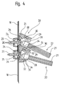
- Fig. 4 shows the section B of FIG. 2 with the Deflector device 20 according to the invention, consisting of a deflector profile 21 with two arranged one above the other Openings 26, the openings 26 in a particular Angles are arranged to each other.
- the one of the in the Openings 26 inserted brush units 22 is thereby aligned somewhat steeper than the other brush unit 22.
- the rest of the structure of the deflector device 20 is comparable to that of FIG. 3, with a first Nose 29 also serves as a second nose 31.
Landscapes
- Escalators And Moving Walkways (AREA)
Abstract
Description
- Fig. 1
- eine Seitenansicht einer Fahrtreppe,
- Fig. 2
- einen Schnitt entlang der Linie A-A der Fig. 1,
- Fig. 3
- einen Ausschnitt B der Fahrtreppe mit der erfindungsgemässen Sicherheitseinrichtung und
- Fig. 4
- einen Ausschnitt B der Fahrtreppe mit einer Ausführungsvariante der erfindungsgemässen Sicherheitseinrichtung.
Claims (5)
- Fahrtreppe (1) oder Fahrsteig bestehend aus einem Träger (8), einem Stufenband (4) mit Stufen (3) bzw. Palettenband mit Paletten für den Transport von Personen und/oder Gegenständen und einer mittels eines Balustradensockels (7) gehaltenen Balustrade (6) mit Handlauf (5), wobei eine am Balustradensockel (7) angeordnete Abweiservorrichtung (20) das Einklemmen von Körperteilen und/oder Gegenständen zwischen dem aus den einzelnen Stufen (3) bestehenden Stufenband und Balustradensockel (7) verhindert,
dadurch gekennzeichnet, dass die Abweiservorrichtung (20) ein am Balustradensockel (7) angeordnetes Abweiserprofil (21) und eine Bürsteneinheit (22) aufweist, wobei die Bürsteneinheit (22) mittels einer Schnappverbindung mit dem Abweiserprofil (21) verbindbar ist. - Fahrtreppe oder Fahrsteig nach Anspruch 1,
dadurch gekennzeichnet, dass das Abweiserprofil (21) eine durch Nasen (29,31) begrenzte Öffnung (26) aufweist, die der Aufnahme eines eine Bürste (27) tragenden Bürstenkörpers (28) der Bürsteneinheit (22) dient. - Fahrtreppe oder Fahrsteig nach den Ansprüchen 1 oder 2,
dadurch gekennzeichnet, dass an einer ersten Nase (29) ein erster Vorsprung (30) und an einer zweiten Nase (31) ein Rücksprung vorgesehen sind, die der Schnappverbindung mit der Bürsteneinheit (22) dienen. - Fahrtreppe oder Fahrsteig nach einem der vorhergehenden Ansprüche,
dadurch gekennzeichnet, dass am Bürstenkörper (28) der Bürsteneinheit (22) ein Schnapphaken (33) vorgesehen ist, der mit dem ersten Vorsprung (30) der ersten Nase (29) verrastet, wobei ein zweiter Vorsprung (34) des Bürstenkörpers (28) vom Rücksprung (32) der zweiten Nase (31) aufgenommen wird. - Fahrtreppe oder Fahrsteig nach einem der vorhergehenden Ansprüche,
dadurch gekennzeichnet, dass die Bürsteneinheit (22) abgelängt oder endlos am Abweiserprofil (21) anbringbar ist.
Priority Applications (1)
| Application Number | Priority Date | Filing Date | Title |
|---|---|---|---|
| EP20020011139 EP1262441B1 (de) | 2001-05-31 | 2002-05-21 | Sicherheitseinrichtung für Fahrtreppe oder Fahrsteig |
Applications Claiming Priority (3)
| Application Number | Priority Date | Filing Date | Title |
|---|---|---|---|
| EP01810527 | 2001-05-31 | ||
| EP01810527 | 2001-05-31 | ||
| EP20020011139 EP1262441B1 (de) | 2001-05-31 | 2002-05-21 | Sicherheitseinrichtung für Fahrtreppe oder Fahrsteig |
Publications (2)
| Publication Number | Publication Date |
|---|---|
| EP1262441A1 true EP1262441A1 (de) | 2002-12-04 |
| EP1262441B1 EP1262441B1 (de) | 2009-12-02 |
Family
ID=26077383
Family Applications (1)
| Application Number | Title | Priority Date | Filing Date |
|---|---|---|---|
| EP20020011139 Expired - Lifetime EP1262441B1 (de) | 2001-05-31 | 2002-05-21 | Sicherheitseinrichtung für Fahrtreppe oder Fahrsteig |
Country Status (1)
| Country | Link |
|---|---|
| EP (1) | EP1262441B1 (de) |
Cited By (2)
| Publication number | Priority date | Publication date | Assignee | Title |
|---|---|---|---|---|
| EP2033930A1 (de) | 2007-09-05 | 2009-03-11 | Inventio Ag | Fahreinrichtung mit Abweiservorrichtung |
| US12122643B2 (en) | 2020-03-30 | 2024-10-22 | Inventio Ag | Positioning aid for positioning a nut on a guide rail of an elevator system |
Families Citing this family (1)
| Publication number | Priority date | Publication date | Assignee | Title |
|---|---|---|---|---|
| BR112016013506B1 (pt) | 2013-12-20 | 2022-08-23 | Inventio Ag | Escada rolante ou esteira rolante, possuindo duas áreas de acesso e método para operar escada rolante ou esteira rolante, possuindo duas áreas de acesso |
Citations (1)
| Publication number | Priority date | Publication date | Assignee | Title |
|---|---|---|---|---|
| GB2343668A (en) * | 1999-12-23 | 2000-05-17 | Jason Inc | Safety guard brush assembly |
-
2002
- 2002-05-21 EP EP20020011139 patent/EP1262441B1/de not_active Expired - Lifetime
Patent Citations (1)
| Publication number | Priority date | Publication date | Assignee | Title |
|---|---|---|---|---|
| GB2343668A (en) * | 1999-12-23 | 2000-05-17 | Jason Inc | Safety guard brush assembly |
Cited By (2)
| Publication number | Priority date | Publication date | Assignee | Title |
|---|---|---|---|---|
| EP2033930A1 (de) | 2007-09-05 | 2009-03-11 | Inventio Ag | Fahreinrichtung mit Abweiservorrichtung |
| US12122643B2 (en) | 2020-03-30 | 2024-10-22 | Inventio Ag | Positioning aid for positioning a nut on a guide rail of an elevator system |
Also Published As
| Publication number | Publication date |
|---|---|
| EP1262441B1 (de) | 2009-12-02 |
Similar Documents
| Publication | Publication Date | Title |
|---|---|---|
| EP0603643B1 (de) | Fahrtreppe mit Stufen, welche seitliche Sicherheitsabgrenzungen aufweisen | |
| EP2033930B1 (de) | Fahreinrichtung mit Abweiservorrichtung | |
| WO2004076330A1 (de) | Rollsteig | |
| DE3148177A1 (de) | Tragkettenfoerderer mit staurollenfoerderketten | |
| EP0745550B1 (de) | Führungsstruktur für einen Aufzug | |
| EP0054687B1 (de) | Führungseinrichtung für die Laufelelemente von Endlosförderern wie Fahrtreppen und dergleichen | |
| EP0607957A1 (de) | Bausatz zur Standardisierung und Bildung eines Baukastensystems für Kettenförderer, Kettenstauförderer und/oder Zahnriemenförderer | |
| EP2417048B1 (de) | Einrichtung zum personentransport | |
| DE2941773C2 (de) | Begrenzungssockel für Fahrtreppen oder Fahrsteige | |
| DE3001993A1 (de) | Rollenanordnung zur befestigung an einer tuer o.dgl. | |
| DE3441845A1 (de) | Bogenrolltreppe mit segmentstufen | |
| EP1262441B1 (de) | Sicherheitseinrichtung für Fahrtreppe oder Fahrsteig | |
| EP0350583A1 (de) | Balustrade einer Fahrtreppe oder eines Personen-Förderbandes | |
| EP1026339A2 (de) | Pfosten | |
| DE20100833U1 (de) | Fahrtreppe oder Fahrsteig | |
| DE112005000182B4 (de) | Umlenkeinrichtungsführung zum Halten eines sich über eine Umlenkeinrichtung bewegenden Handlaufs | |
| DE3602945A1 (de) | Glasbalustrade fuer fahrtreppen und fahrsteige | |
| DE3028489C2 (de) | Materiallager | |
| DE10125686B4 (de) | Stufenbefestigung an der Stufenkette einer Fahrtreppe | |
| EP1142821B1 (de) | Trennwand für Fahrtreppe oder Fahrsteig | |
| DE8126440U1 (de) | Rahmen fuer bandfoerdervorrichtungen | |
| EP1236672B1 (de) | Balustrade für Fahrtreppe oder Fahrsteig | |
| DE1683263A1 (de) | Vorgefertigtes Treppenelement | |
| DE2845309C2 (de) | Handlauf oder Wange für gerade oder gewendelte Treppenabschnitte | |
| DE2703297A1 (de) | Rolltreppe |
Legal Events
| Date | Code | Title | Description |
|---|---|---|---|
| PUAI | Public reference made under article 153(3) epc to a published international application that has entered the european phase |
Free format text: ORIGINAL CODE: 0009012 |
|
| AK | Designated contracting states |
Kind code of ref document: A1 Designated state(s): AT BE CH CY DE DK ES FI FR GB GR IE IT LI LU MC NL PT SE TR |
|
| AX | Request for extension of the european patent |
Free format text: AL;LT;LV;MK;RO;SI |
|
| 17P | Request for examination filed |
Effective date: 20030516 |
|
| AKX | Designation fees paid |
Designated state(s): AT CH DE FR GB LI |
|
| 17Q | First examination report despatched |
Effective date: 20090306 |
|
| GRAP | Despatch of communication of intention to grant a patent |
Free format text: ORIGINAL CODE: EPIDOSNIGR1 |
|
| GRAS | Grant fee paid |
Free format text: ORIGINAL CODE: EPIDOSNIGR3 |
|
| GRAA | (expected) grant |
Free format text: ORIGINAL CODE: 0009210 |
|
| AK | Designated contracting states |
Kind code of ref document: B1 Designated state(s): AT CH DE FR GB LI |
|
| REG | Reference to a national code |
Ref country code: GB Ref legal event code: FG4D Free format text: NOT ENGLISH |
|
| REG | Reference to a national code |
Ref country code: CH Ref legal event code: EP |
|
| REF | Corresponds to: |
Ref document number: 50214031 Country of ref document: DE Date of ref document: 20100114 Kind code of ref document: P |
|
| PLBE | No opposition filed within time limit |
Free format text: ORIGINAL CODE: 0009261 |
|
| STAA | Information on the status of an ep patent application or granted ep patent |
Free format text: STATUS: NO OPPOSITION FILED WITHIN TIME LIMIT |
|
| 26N | No opposition filed |
Effective date: 20100903 |
|
| REG | Reference to a national code |
Ref country code: CH Ref legal event code: PL |
|
| PG25 | Lapsed in a contracting state [announced via postgrant information from national office to epo] |
Ref country code: CH Free format text: LAPSE BECAUSE OF NON-PAYMENT OF DUE FEES Effective date: 20100531 Ref country code: LI Free format text: LAPSE BECAUSE OF NON-PAYMENT OF DUE FEES Effective date: 20100531 |
|
| PG25 | Lapsed in a contracting state [announced via postgrant information from national office to epo] |
Ref country code: AT Free format text: LAPSE BECAUSE OF NON-PAYMENT OF DUE FEES Effective date: 20100521 |
|
| REG | Reference to a national code |
Ref country code: FR Ref legal event code: PLFP Year of fee payment: 15 |
|
| REG | Reference to a national code |
Ref country code: FR Ref legal event code: PLFP Year of fee payment: 16 |
|
| REG | Reference to a national code |
Ref country code: FR Ref legal event code: PLFP Year of fee payment: 17 |
|
| PGFP | Annual fee paid to national office [announced via postgrant information from national office to epo] |
Ref country code: DE Payment date: 20180522 Year of fee payment: 17 |
|
| PGFP | Annual fee paid to national office [announced via postgrant information from national office to epo] |
Ref country code: FR Payment date: 20180522 Year of fee payment: 17 |
|
| PGFP | Annual fee paid to national office [announced via postgrant information from national office to epo] |
Ref country code: GB Payment date: 20180518 Year of fee payment: 17 |
|
| REG | Reference to a national code |
Ref country code: DE Ref legal event code: R119 Ref document number: 50214031 Country of ref document: DE |
|
| GBPC | Gb: european patent ceased through non-payment of renewal fee |
Effective date: 20190521 |
|
| PG25 | Lapsed in a contracting state [announced via postgrant information from national office to epo] |
Ref country code: GB Free format text: LAPSE BECAUSE OF NON-PAYMENT OF DUE FEES Effective date: 20190521 Ref country code: DE Free format text: LAPSE BECAUSE OF NON-PAYMENT OF DUE FEES Effective date: 20191203 |
|
| PG25 | Lapsed in a contracting state [announced via postgrant information from national office to epo] |
Ref country code: FR Free format text: LAPSE BECAUSE OF NON-PAYMENT OF DUE FEES Effective date: 20190531 |