EP2033863B1 - Hydrostatic braking system - Google Patents
Hydrostatic braking system Download PDFInfo
- Publication number
- EP2033863B1 EP2033863B1 EP07115671A EP07115671A EP2033863B1 EP 2033863 B1 EP2033863 B1 EP 2033863B1 EP 07115671 A EP07115671 A EP 07115671A EP 07115671 A EP07115671 A EP 07115671A EP 2033863 B1 EP2033863 B1 EP 2033863B1
- Authority
- EP
- European Patent Office
- Prior art keywords
- braking system
- gear
- fluid
- compartment
- channel
- Prior art date
- Legal status (The legal status is an assumption and is not a legal conclusion. Google has not performed a legal analysis and makes no representation as to the accuracy of the status listed.)
- Not-in-force
Links
Images


Classifications
-
- B—PERFORMING OPERATIONS; TRANSPORTING
- B60—VEHICLES IN GENERAL
- B60T—VEHICLE BRAKE CONTROL SYSTEMS OR PARTS THEREOF; BRAKE CONTROL SYSTEMS OR PARTS THEREOF, IN GENERAL; ARRANGEMENT OF BRAKING ELEMENTS ON VEHICLES IN GENERAL; PORTABLE DEVICES FOR PREVENTING UNWANTED MOVEMENT OF VEHICLES; VEHICLE MODIFICATIONS TO FACILITATE COOLING OF BRAKES
- B60T10/00—Control or regulation for continuous braking making use of fluid or powdered medium, e.g. for use when descending a long slope
- B60T10/04—Control or regulation for continuous braking making use of fluid or powdered medium, e.g. for use when descending a long slope with hydrostatic brake
-
- F—MECHANICAL ENGINEERING; LIGHTING; HEATING; WEAPONS; BLASTING
- F16—ENGINEERING ELEMENTS AND UNITS; GENERAL MEASURES FOR PRODUCING AND MAINTAINING EFFECTIVE FUNCTIONING OF MACHINES OR INSTALLATIONS; THERMAL INSULATION IN GENERAL
- F16D—COUPLINGS FOR TRANSMITTING ROTATION; CLUTCHES; BRAKES
- F16D57/00—Liquid-resistance brakes; Brakes using the internal friction of fluids or fluid-like media, e.g. powders
- F16D57/06—Liquid-resistance brakes; Brakes using the internal friction of fluids or fluid-like media, e.g. powders comprising a pump circulating fluid, braking being effected by throttling of the circulation
Definitions
- the present invention relates to braking systems, and in particular, liquid resistance braking systems.
- Friction brakes such as drum brakes or disc brakes are commonly used for slowing and stopping rotating shafts in vehicles and machinery.
- a particular disadvantage is the wear on the brake pads or shoes and discs, which are brought into contact to slow the rotary motion of the shaft by friction.
- a further disadvantage is the generation of heat by friction and also the need to remove that heat to avoid deformation.
- a simple gear pump 100 is shown in Figure 1 of the accompanying drawings.
- the gear pump comprises a driver gear 102 and an idle gear 104 arranged in a housing 101. Rotation of driver gear 102 by shaft 103 causes gear 104 to rotate. As the gears 102, 104 rotate they separate on the inlet side 105 of the pump 100. This creates an area of lower pressure on the inlet side 105, thereby drawing fluid into the pump.
- the fluid is carried by the gears 102, 104 (in small volumes 107) to the outlet side 106, where the meshing of the gears displaces the fluid.
- the mechanical clearances in gear pumps are small to prevent the fluid from leaking backwards.
- Liquid resistance brakes use the basic principle of a gear pump but with the inlet and outlet connected together through a valve. While the valve remains open, the shaft can freely turn, pumping fluid around the system. Once the valve is closed, the fluid pressure increases and restricts rotation of the gears and thus of the shaft.
- liquid resistance brakes are particularly suitable in applications where the maintenance costs of replacing worn brake pads are high or where heavy and constant wear makes brake pads too expensive to operate (such as in large sized vehicles like mining trucks).
- the non-friction operation is also of use in applications where heat generation or material distortion is a problem (such as in micro braking applications or explosive environments).
- Liquid resistance brakes are also suitable for regenerative braking applications where the excess energy generated during braking can be captured and reapplied to an alternative task (such as in regenerative braking systems used in light rail systems and next generation Formula One cars).
- the apparatus comprises a fluid-tight housing in which is disposed a shaft rotational engagement gear having an exteriorly-accessible portion thereof rotatably engageable with a shaft.
- a plurality of compartments are formed with the housing and the compartments are in fluid communication with each other through openable and closable valves.
- the housing is substantially filled with a fluid which is flowable through the valves in direct relation to the openness of the valves.
- the apparatus further comprises a plurality of compartment-divider gears rotatably engaged with the shaft rotational gear and situated in cooperation with the compartment walls to create restriction seals between the compartments.
- a disadvantage of this system is that the brake will always be substantially larger in diameter than the shaft, resulting in an additional space requirement and an additional cost in terms of components.
- US Patent No. 2,758,573 discloses a gear type hydraulic unit which employs an internally toothed annular member in conjunction with an externally toothed inner member in mesh with the teeth of the annular member.
- a braking system comprising:
- the means for controlling the flow of fluid within the system may comprise a valve, wherein the valve is closeable to restrict the flow of fluid within the system, thereby restricting relative rotational motion between the planet gears and the annulus gear.
- the valve may be arranged between two sides of a planet gear, or between a pair of planet gears.
- the or each planet gear may be arranged within a compartment to divide the compartment into at least two portions. At least one channel may be provided in the divider, wherein the or each channel is disposed between a first compartment portion and a second compartment portion. The fluid is flowable through the channel. A valve may be disposed in the or each channel, wherein the valve is closeable to restrict the flow of fluid within the system, thereby restricting relative rotational motion between the planet gears and the annulus gear.
- the braking system may comprise a pair of cover plates, which together with the annulus gear, provide a housing for the braking system.
- the housing is preferably fluid-tight.
- One plate may be connected to the annulus gear and the other plate to the divider and/or to the central axis of the or each planet gear.
- the central axis of the or each planet gear may be fixed relative to the divider.
- the planet gears may extend through one of the plates for direct connection to an element to which braking is to be applied.
- the cover plates may be rotatable relative to one another.
- the or each planet gear may be arranged within a compartment such that it is substantially flush with the wall of the compartment at at least one point, thereby dividing the compartment into at least two portions.
- the or each channel may be disposed between two portions of a single compartment, or may be disposed between two portions of different compartments.
- the braking system may include a plurality of planet gears, each planet gear arranged within a corresponding compartment and rotatably engaged with the annulus gear.
- the system may comprise a corresponding plurality of channels.
- each channel is disposed between a pair of planet gears. Channels may be linked together to reduce the number of valves required.
- the number of planet gears and the size of those gears may be selected to optimise the desired performance of the braking system for a given set of operating parameters (torque, size, desired gear ratio etc.)
- the braking system may be used to apply a braking force between a first rotatable element, such as a shaft, wheel, or conveyor belt, attached to the annulus gear and a second fixed element, such as a wall, vehicle chassis, or other fixed object, attached to the divider. Restricting flow of fluid within the system to restrict relative rotational motion between the planet gears and the annulus gear causes braking of the rotatable element.
- the arrangement may also be reversed, so that the annulus gear is attached to the fixed element and the divider is connected to the rotatable element.
- the braking system may also be used to apply a force between two rotatable elements, for example, two shafts.
- restricting flow of fluid in the system to restrict relative rotational motion between the planet gears and the annulus gear restricts rotation of the rotatable elements relative to one another, thus providing a driving engagement therebetween.
- the braking system thus provides relative braking between the two rotatable elements.
- a first shaft may be rotatably driven by drive means, and a second shaft is coupled to the first shaft by the braking system of the present invention. Restricting the flow of fluid within the braking system restricts relative rotational motion between the first and second shafts, thereby causing rotation of the second shaft.
- the braking system of the present invention is a system for controlling, impeding or restricting relative rotational motion between two elements.
- the system may alternately be described as a rotational locking mechanism, a rotational coupling means or a rotational impedance device.
- the system may be used to stop rotational motion (by preventing relative rotational motion between a rotating element and a fixed element) or to cause rotational motion (by preventing relative rotational motion between a driven element and a driveable element).
- the braking system may be incorporated into a rotatable shaft, for example, a drive shaft.
- the arrangement of the present invention has several advantages over known liquid resistance braking systems.
- the present invention will provide higher braking torque than the "external" braking system described in US Patent No. 5,558,187 and will therefore stop more quickly.
- the present invention therefore requires less space and involves a lower cost to achieve the required level of torque.
- the braking system may be provided within a shaft.
- a first element such as a rotatable shaft, wheel or conveyor belt
- a cover plate is attached to the annulus gear and the first element is attached thereto.
- a second (fixed) element is connected to the divider.
- a cover plate is attached to the divider and the second element is attached thereto. Restricting the flow of fluid within the system causes braking of the first element with respect to the second element.
- the first element may be connected directly to the annulus gear (or cover plate) or may be connected through at least one other gear to provide the desired rotational ratio or torque.
- the system may comprise a single planet gear disposed within a single compartment within the divider, dividing the compartment into two portions.
- a single channel in the divider connects the two compartment portions.
- a back cover plate may be connected to the central axis of the planet gear, so that the planet gear is free to rotate on this axis.
- the back plate is also connected to the divider and to a stationary element, for example, a wall.
- a front cover plate may be connected to the annulus gear and a rotatable shaft may be connected thereto. When the shaft rotates, the front plate and annulus gear also rotate, and the planet gear is in turn caused to rotate by means of engagement with the annulus gear.
- the valve in the channel is closed, the flow of fluid through the channel is restricted, thereby restricting relative motion between the planet gear and the annulus gear, causing braking of the shaft.
- the first element is connected to the divider, preferably by attachment to a cover plate.
- the first element may be connected directly to the divider (or cover plate) or may be connected through at least one other gear to provide the desired rotational ration or torque.
- the first element is connected to a planet gear, preferably by attachment to a cover plate.
- the first element may be connected directly to the planet gear (or cover plate) or may be connected through at least one other gear to provide the desired rotational ratio or torque.
- the braking system may also be used to connect two shafts together.
- a first shaft is connected to the annulus gear.
- a cover plate is attached to the annulus gear and the first shaft is attached thereto.
- a second shaft is connected to the divider.
- a cover plate is attached to the divider and the second shaft is attached thereto. Restricting the flow of fluid in the system, for example, by closing a valve, causes a driving engagement between the first and second shafts.
- the planet gears can rotate and so the first and second shafts can rotate relative to one another.
- fixed or rotatable elements may be connected to the planet gear or gears.
- the planet gear may be directly connected to an element, or its central axis may be attached to a cover plate which is in turn attached to the element.
- the divider and the planet gears may be connected to the same element.
- the fluid contained in the braking system is preferably a substantially non-compressible hydraulic fluid.
- the fluid should preferably be able to withstand high pressure and temperature without vaporisation.
- the fluid may be an oil.
- the braking system may further comprise means for removing or inserting fluid to control the fluid pressure within the housing or for use in regenerative braking.
- a shaft comprising a braking system as described above.
- FIG 2 shows an embodiment of a braking system 1 according to the present invention.
- the braking system comprises an annulus gear 3 connected to a front plate (not shown).
- the system also comprises a divider 12 arranged within the annulus gear 3 to create an internal compartment 14.
- the divider 12 is connected to a back plate (not shown).
- the front and back plates, together with the annulus gear, form a housing for the braking system.
- the system also comprises a planet gear 4 rotatably engaged with the annulus gear 3 by means of interlocking teeth 6, 7 and arranged within the compartment 14 to divide the compartment into two portions 11, 13.
- the central axis of the planet gear is also connected to the back plate.
- the braking system also includes a channel 8 formed in the divider 12.
- the channel 8 is disposed between the two portions 11, 13 of the compartment 14.
- a fluid is provided within the housing. The fluid is flowable through the channel 8.
- the braking system 1 further comprises a valve 10 disposed in the channel 8, wherein the valve 10 is closeable to restrict the flow of fluid through the channel.
- valve 10 When it is desired to stop or slow the annulus gear (and thus the shaft, pulley, wheel or belt to which the annulus gear is connected) the valve 10 is closed.
- the valve may be either fully or partially closed, depending on the degree of braking required. Closing the valve prevents (or restricts) the flow of fluid through the channel. The fluid pressure at region 11 is therefore increased. This increase in pressure prevents (or restricts) rotation of the planet gear 4, which in turn prevents (or restricts) rotation of the annulus gear 3, thereby resulting in stopping (or slowing) of the shaft or other element to which the annulus gear is connected.
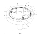
- FIGs 3 and 4 show a second embodiment of a braking system 1 according to the present invention.
- the braking system comprises an annulus gear 3, which forms part of the braking system housing.
- the annulus gear is connected to a first shaft 2a.
- the system further comprises a divider 12 arranged within the annulus gear 3 to create two internal compartments 14a, 14b.
- the divider 12 is connected to a second shaft 2b.
- the system 1 further comprises two planet gears 4a, 4b, each arranged within a respective compartment 14a, 14b.
- the planet gears 4a, 4b are rotatably engaged with the annulus gear by means of interlocking teeth 6, 7.
- the planet gears are free to rotate on their axes.
- the divider and the central axes of the planet gears are linked, for example by a cover plate (not shown).
- the braking system also includes two channels 8a, 8b formed in the divider 12. Each channel 8a, 8b is disposed between the two compartments 14a, 14b. A fluid is provided within the housing. The fluid is flowable through the channels 8.
- the braking system 1 further comprises a valve 10a, 10b disposed in each channel, wherein the valves 10 are closeable to restrict the flow of fluid through the respective channel.
- valves 10 When it is desired to stop or slow the shaft 2a, the valves 10 are closed.
- the valves may be either fully or partially closed, depending on the degree of braking required. Closing the valves prevents (or restricts) the flow of fluid through the channels.
- the fluid pressure at regions 11a and 11b is therefore increased. This increase in pressure prevents (or restricts) rotation of the planet gears 4, which in turn prevents (or restricts) rotation of the annulus gear 3, thereby resulting in stopping (or slowing) of rotation of the attached shaft 2a.
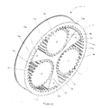
- FIGs 5 and 6 show a third embodiment of a braking system 1.
- the braking system comprises an annulus gear 3.
- the annulus gear forms part of a housing for the braking system.
- the system 1 further comprises three driven planet gears 4a, 4b, 4c arranged within the annulus gear 3.
- the planet gears 4a, 4b, 4c are rotatably engaged with the annulus gear by means of interlocking teeth 6, 7.
- the system further comprises a divider 12 arranged within the annulus gear 3 to create an internal compartment 14a, 14b, 14c for each planet gear 4a, 4b, 4c.
- Each planet gear 4 is arranged within a compartment 14 to divide the compartment into two portions 11a,b,c, 13a,b,c.
- the planet gears 4 are free to rotate on their axes.
- the divider is linked to the central axes of the planet gears, for example by means of a cover plate (not shown).
- One or more elements such as a rotatable shaft, a pulley or a belt may be connected to the annulus gear, the divider, or a planet gear, for example, by means of front and back cover plates forming part of the housing of the braking system.
- the braking system also includes three channels 8a, 8b, 8c formed in the divider 12. As in the embodiment shown in Figures 3 and 4 , each channel 8a, 8b, 8c is disposed between a pair of planet gears 4a, 4b, 4c. A fluid is provided within the housing. The fluid is flowable through the channels 8.
- the braking system 1 further comprises a valve 10a, 10b, 10c disposed in each channel, wherein the valve 10 is closeable to restrict the flow of fluid through the respective channel.
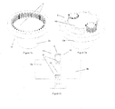
- FIG. 7 Another arrangement of the braking system of the present invention is shown in Figure 7 , in which the braking system is used to connect two shafts 2a, 2b together.
- the first shaft 2a is connected to the front plate 15 of the braking system and thus to the annulus gear 3.
- the second shaft 2b is connected to the back plate 16 and thus to the divider 12.
- the central axes of the planet gears 4a, 4b are also connected to back plate 16.
- the braking system 1 operates substantially as described above with reference to the other drawings. Closing the valves 10 to restrict relative rotational motion between the planet gears 4a, 4b and the annulus gear 3 causes a driving engagement between the first and second shafts 2a, 2b.
- the planet gears 4 When the valves 10 are open, the planet gears 4 can rotate and so the first and second shafts 2a, 2b can rotate relative to one another.
- This type of system may be used to couple a driven shaft to a driveable shaft. For example, if shaft 2a is rotatably driven by a drive means, closing the valves 10 will restrict relative rotational motion between shaft 2a and shaft 2b, thereby causing shaft 2b to rotate with shaft 2a.
- This type of system may also be used as a variable torque delivery system or as a safety disengagement system.
- FIG 8 Another arrangement is shown in Figure 8 .
- This arrangement is similar to that shown in Figure 7 except that the back plate 16 is connected to a fixed object, such as a wall 5, instead of a shaft.
- closing the valves to restrict relative rotational motion between the planet gears 4 and the annulus gear 3 causes the shaft 2 to brake.
- the valves When the valves are open, the planet gears can rotate and the shaft is also free to rotate.
- Such a system may be used to provide variable braking to the shaft.
- FIG. 9 Another arrangement is shown in Figure 9 .
- This arrangement is similar to that shown in Figure 8 , except that the annulus gear is driven by a belt 2 instead of a shaft.
- the operation of the system us is otherwise the same as described above for Figure 8 .
Landscapes
- Engineering & Computer Science (AREA)
- General Engineering & Computer Science (AREA)
- Mechanical Engineering (AREA)
- Transportation (AREA)
- Braking Arrangements (AREA)
- Hydraulic Motors (AREA)
- Mechanically-Actuated Valves (AREA)
- Transmission Of Braking Force In Braking Systems (AREA)
- Retarders (AREA)
Priority Applications (12)
| Application Number | Priority Date | Filing Date | Title |
|---|---|---|---|
| AT07115671T ATE450419T1 (de) | 2007-09-04 | 2007-09-04 | Hydrostatisches bremssystem |
| EP07115671A EP2033863B1 (en) | 2007-09-04 | 2007-09-04 | Hydrostatic braking system |
| ES07115671T ES2336501T3 (es) | 2007-09-04 | 2007-09-04 | Sistema de frenado hidrostatico. |
| DE602007003601T DE602007003601D1 (de) | 2007-09-04 | 2007-09-04 | Hydrostatisches Bremssystem |
| DK07115671.5T DK2033863T3 (da) | 2007-09-04 | 2007-09-04 | Hydrostatisk bremsesystem |
| CA2697928A CA2697928A1 (en) | 2007-09-04 | 2008-09-03 | Braking system |
| AU2008294781A AU2008294781B2 (en) | 2007-09-04 | 2008-09-03 | Hydrostatic braking system |
| JP2010523499A JP2010538227A (ja) | 2007-09-04 | 2008-09-03 | 液圧ブレーキシステム |
| PCT/EP2008/061643 WO2009030712A2 (en) | 2007-09-04 | 2008-09-03 | Hydrostatic braking system |
| RU2010112925/11A RU2475385C2 (ru) | 2007-09-04 | 2008-09-03 | Тормозная система |
| US12/676,425 US8439784B2 (en) | 2007-09-04 | 2008-09-03 | Braking system |
| CN200880105607.9A CN101842276B (zh) | 2007-09-04 | 2008-09-03 | 流体静力制动系统 |
Applications Claiming Priority (1)
| Application Number | Priority Date | Filing Date | Title |
|---|---|---|---|
| EP07115671A EP2033863B1 (en) | 2007-09-04 | 2007-09-04 | Hydrostatic braking system |
Publications (2)
| Publication Number | Publication Date |
|---|---|
| EP2033863A1 EP2033863A1 (en) | 2009-03-11 |
| EP2033863B1 true EP2033863B1 (en) | 2009-12-02 |
Family
ID=39110565
Family Applications (1)
| Application Number | Title | Priority Date | Filing Date |
|---|---|---|---|
| EP07115671A Not-in-force EP2033863B1 (en) | 2007-09-04 | 2007-09-04 | Hydrostatic braking system |
Country Status (12)
| Country | Link |
|---|---|
| US (1) | US8439784B2 (zh) |
| EP (1) | EP2033863B1 (zh) |
| JP (1) | JP2010538227A (zh) |
| CN (1) | CN101842276B (zh) |
| AT (1) | ATE450419T1 (zh) |
| AU (1) | AU2008294781B2 (zh) |
| CA (1) | CA2697928A1 (zh) |
| DE (1) | DE602007003601D1 (zh) |
| DK (1) | DK2033863T3 (zh) |
| ES (1) | ES2336501T3 (zh) |
| RU (1) | RU2475385C2 (zh) |
| WO (1) | WO2009030712A2 (zh) |
Families Citing this family (5)
| Publication number | Priority date | Publication date | Assignee | Title |
|---|---|---|---|---|
| DE102010056106B4 (de) * | 2010-12-23 | 2012-07-19 | Magna Powertrain Ag & Co. Kg | Getriebeeinheit |
| JP6007047B2 (ja) * | 2012-09-28 | 2016-10-12 | ボッシュ株式会社 | Abs液圧ユニット |
| KR102280290B1 (ko) * | 2015-05-18 | 2021-07-20 | 가부시키가이샤 티비케이 | 기어 펌프 |
| CN105909697A (zh) * | 2016-06-16 | 2016-08-31 | 杨靖康 | 一种非摩擦制动器 |
| US10731735B1 (en) * | 2018-03-19 | 2020-08-04 | Mainstream Engineering Corporation | Power transfer system and method using a variable speed ratio regulating device |
Family Cites Families (19)
| Publication number | Priority date | Publication date | Assignee | Title |
|---|---|---|---|---|
| US2371228A (en) * | 1945-03-13 | Torque transmission | ||
| US1368476A (en) * | 1918-07-26 | 1921-02-15 | Ransom Y Bovee | Transmission-gearing |
| US2758573A (en) * | 1954-12-20 | 1956-08-14 | Krozal William | Gear type hydraulic unit |
| GB768791A (en) * | 1955-04-20 | 1957-02-20 | Robert Gallay | Fluid-pressure braking device for motor-vehicles |
| US2933158A (en) * | 1956-07-23 | 1960-04-19 | Howard E Pitts | Auxiliary brake for vehicle |
| GB1083082A (en) * | 1965-03-01 | 1967-09-13 | Iso Speedic Company Ltd | Improvements in self-operating mechanisms for retarding the movement of an object down an inclined runway |
| GB1251536A (zh) * | 1967-12-28 | 1971-10-27 | ||
| US3802813A (en) * | 1970-04-01 | 1974-04-09 | Plessey Co Ltd | Fluid-displacement machines |
| JPS496799A (zh) * | 1972-05-08 | 1974-01-21 | ||
| JPS5342868B2 (zh) * | 1973-02-27 | 1978-11-15 | ||
| SU640882A1 (ru) * | 1976-07-12 | 1979-01-05 | Предприятие П/Я В-2330 | Гидростатический роторный тормоз транспортного средства |
| JPS59741B2 (ja) * | 1976-11-05 | 1984-01-09 | 英光 合田 | 滑車等の巻掛け回転被動部材の制動装置 |
| EP0400508B1 (de) * | 1989-06-02 | 1994-09-28 | Rohs, Ulrich, Dr. | Vorrichtung zur Änderung der zeitlichen Durchflussmenge bei einem Drehschwingungsdämpfer |
| US5558187A (en) * | 1995-06-07 | 1996-09-24 | Aberle; David H. | Brake apparatus for a rotating shaft |
| JP2001508156A (ja) * | 1996-04-04 | 2001-06-19 | ボールドウィン,フレッド・エル | 遊星歯車ポンプを備えた静圧カップリング |
| DE19733673A1 (de) * | 1997-08-04 | 1999-02-11 | Zahnradfabrik Friedrichshafen | Formschlüssige Schaltkupplung |
| US7025700B1 (en) * | 2003-05-15 | 2006-04-11 | Kurtis Rex Hoelscher | Closed-loop hydraulic adjustable slip differential |
| CN2752118Y (zh) * | 2004-08-16 | 2006-01-18 | 北汽福田汽车股份有限公司 | 一种用于车辆排气制动的真空电磁阀 |
| JP2010510452A (ja) * | 2006-11-20 | 2010-04-02 | ヤナイ,ジョセフ | 連続可変トランスミッションベースの遊星歯車 |
-
2007
- 2007-09-04 DK DK07115671.5T patent/DK2033863T3/da active
- 2007-09-04 ES ES07115671T patent/ES2336501T3/es active Active
- 2007-09-04 DE DE602007003601T patent/DE602007003601D1/de active Active
- 2007-09-04 AT AT07115671T patent/ATE450419T1/de not_active IP Right Cessation
- 2007-09-04 EP EP07115671A patent/EP2033863B1/en not_active Not-in-force
-
2008
- 2008-09-03 US US12/676,425 patent/US8439784B2/en active Active
- 2008-09-03 RU RU2010112925/11A patent/RU2475385C2/ru not_active IP Right Cessation
- 2008-09-03 JP JP2010523499A patent/JP2010538227A/ja active Pending
- 2008-09-03 CN CN200880105607.9A patent/CN101842276B/zh not_active Expired - Fee Related
- 2008-09-03 CA CA2697928A patent/CA2697928A1/en not_active Abandoned
- 2008-09-03 AU AU2008294781A patent/AU2008294781B2/en not_active Ceased
- 2008-09-03 WO PCT/EP2008/061643 patent/WO2009030712A2/en active Application Filing
Also Published As
| Publication number | Publication date |
|---|---|
| DE602007003601D1 (de) | 2010-01-14 |
| DK2033863T3 (da) | 2010-03-08 |
| EP2033863A1 (en) | 2009-03-11 |
| US8439784B2 (en) | 2013-05-14 |
| CA2697928A1 (en) | 2009-03-12 |
| WO2009030712A2 (en) | 2009-03-12 |
| RU2010112925A (ru) | 2011-10-10 |
| RU2475385C2 (ru) | 2013-02-20 |
| US20110130236A1 (en) | 2011-06-02 |
| JP2010538227A (ja) | 2010-12-09 |
| AU2008294781A1 (en) | 2009-03-12 |
| AU2008294781B2 (en) | 2011-12-01 |
| ATE450419T1 (de) | 2009-12-15 |
| ES2336501T3 (es) | 2010-04-13 |
| CN101842276A (zh) | 2010-09-22 |
| WO2009030712A3 (en) | 2009-06-04 |
| CN101842276B (zh) | 2012-07-04 |
Similar Documents
| Publication | Publication Date | Title |
|---|---|---|
| EP1862344B1 (en) | Hydraulic power transmission device and work vehicle | |
| US4271725A (en) | Hydraulic motor unit | |
| US5971880A (en) | Infinitely variable ratio transmission | |
| EP2033863B1 (en) | Hydrostatic braking system | |
| JP2010510452A (ja) | 連続可変トランスミッションベースの遊星歯車 | |
| DE102006059155A1 (de) | Kraftfahrzeuggetriebe mit einem Differentialmechanismus, der von einer nach Bedarf schaltbaren Kupplung gesteuert wird | |
| KR20150038041A (ko) | 회전하는 브레이크-해방 피스톤을 갖는 결합된 모터 및 브레이크 | |
| WO2010113018A1 (en) | Hydraulic coupling having improved hydraulic porting path design | |
| WO2012078251A1 (en) | Transmission assembly having variable force clutch | |
| US6830529B2 (en) | Torque transfer assembly with planetary differential | |
| US7070532B2 (en) | Planetary transmission having a rotating-type torque-transmitting mechanism with a stationary piston | |
| MX2012010908A (es) | Acoplamiento hidraulico teniendo diseño de trayectoria de compuerta hidraulica mejorado. | |
| EP1070847A2 (en) | Hydraulic gerotor motor and parking brake | |
| JP4171998B2 (ja) | 回転流体圧装置 | |
| JPH09210102A (ja) | クラッチを制御するための装置 | |
| US5766108A (en) | Continuously variable transmission utilizing variable viscous coupling | |
| EP4286709A1 (en) | Vehicle axle device | |
| WO2002066862A1 (fr) | Transmission variable en continu et commandee par un fluide | |
| CN116424031A (zh) | 双速驱动桥系统及车辆 | |
| JP3742130B2 (ja) | ディファレンシャル装置 | |
| JP3300393B2 (ja) | 四輪駆動車用駆動力伝達装置 | |
| GB2313652A (en) | Hydraulic transmission unit | |
| US20120318620A1 (en) | Oil cooled brake |
Legal Events
| Date | Code | Title | Description |
|---|---|---|---|
| PUAI | Public reference made under article 153(3) epc to a published international application that has entered the european phase |
Free format text: ORIGINAL CODE: 0009012 |
|
| 17P | Request for examination filed |
Effective date: 20080730 |
|
| AK | Designated contracting states |
Kind code of ref document: A1 Designated state(s): AT BE BG CH CY CZ DE DK EE ES FI FR GB GR HU IE IS IT LI LT LU LV MC MT NL PL PT RO SE SI SK TR |
|
| AX | Request for extension of the european patent |
Extension state: AL BA HR MK RS |
|
| GRAP | Despatch of communication of intention to grant a patent |
Free format text: ORIGINAL CODE: EPIDOSNIGR1 |
|
| GRAS | Grant fee paid |
Free format text: ORIGINAL CODE: EPIDOSNIGR3 |
|
| GRAA | (expected) grant |
Free format text: ORIGINAL CODE: 0009210 |
|
| RAP1 | Party data changed (applicant data changed or rights of an application transferred) |
Owner name: TECHNOLOGY FROM IDEAS |
|
| AKX | Designation fees paid |
Designated state(s): AT BE BG CH CY CZ DE DK EE ES FI FR GB GR HU IE IS IT LI LT LU LV MC MT NL PL PT RO SE SI SK TR |
|
| AK | Designated contracting states |
Kind code of ref document: B1 Designated state(s): AT BE BG CH CY CZ DE DK EE ES FI FR GB GR HU IE IS IT LI LT LU LV MC MT NL PL PT RO SE SI SK TR |
|
| REG | Reference to a national code |
Ref country code: GB Ref legal event code: FG4D |
|
| REG | Reference to a national code |
Ref country code: CH Ref legal event code: EP |
|
| REG | Reference to a national code |
Ref country code: IE Ref legal event code: FG4D |
|
| REF | Corresponds to: |
Ref document number: 602007003601 Country of ref document: DE Date of ref document: 20100114 Kind code of ref document: P |
|
| REG | Reference to a national code |
Ref country code: DK Ref legal event code: T3 |
|
| REG | Reference to a national code |
Ref country code: NL Ref legal event code: VDEP Effective date: 20091202 |
|
| REG | Reference to a national code |
Ref country code: ES Ref legal event code: FG2A Ref document number: 2336501 Country of ref document: ES Kind code of ref document: T3 |
|
| PG25 | Lapsed in a contracting state [announced via postgrant information from national office to epo] |
Ref country code: FI Free format text: LAPSE BECAUSE OF FAILURE TO SUBMIT A TRANSLATION OF THE DESCRIPTION OR TO PAY THE FEE WITHIN THE PRESCRIBED TIME-LIMIT Effective date: 20091202 Ref country code: LT Free format text: LAPSE BECAUSE OF FAILURE TO SUBMIT A TRANSLATION OF THE DESCRIPTION OR TO PAY THE FEE WITHIN THE PRESCRIBED TIME-LIMIT Effective date: 20091202 Ref country code: SE Free format text: LAPSE BECAUSE OF FAILURE TO SUBMIT A TRANSLATION OF THE DESCRIPTION OR TO PAY THE FEE WITHIN THE PRESCRIBED TIME-LIMIT Effective date: 20091202 |
|
| LTIE | Lt: invalidation of european patent or patent extension |
Effective date: 20091202 |
|
| PG25 | Lapsed in a contracting state [announced via postgrant information from national office to epo] |
Ref country code: LV Free format text: LAPSE BECAUSE OF FAILURE TO SUBMIT A TRANSLATION OF THE DESCRIPTION OR TO PAY THE FEE WITHIN THE PRESCRIBED TIME-LIMIT Effective date: 20091202 Ref country code: CY Free format text: LAPSE BECAUSE OF FAILURE TO SUBMIT A TRANSLATION OF THE DESCRIPTION OR TO PAY THE FEE WITHIN THE PRESCRIBED TIME-LIMIT Effective date: 20091202 Ref country code: SI Free format text: LAPSE BECAUSE OF FAILURE TO SUBMIT A TRANSLATION OF THE DESCRIPTION OR TO PAY THE FEE WITHIN THE PRESCRIBED TIME-LIMIT Effective date: 20091202 Ref country code: PL Free format text: LAPSE BECAUSE OF FAILURE TO SUBMIT A TRANSLATION OF THE DESCRIPTION OR TO PAY THE FEE WITHIN THE PRESCRIBED TIME-LIMIT Effective date: 20091202 |
|
| PG25 | Lapsed in a contracting state [announced via postgrant information from national office to epo] |
Ref country code: AT Free format text: LAPSE BECAUSE OF FAILURE TO SUBMIT A TRANSLATION OF THE DESCRIPTION OR TO PAY THE FEE WITHIN THE PRESCRIBED TIME-LIMIT Effective date: 20091202 |
|
| PG25 | Lapsed in a contracting state [announced via postgrant information from national office to epo] |
Ref country code: RO Free format text: LAPSE BECAUSE OF FAILURE TO SUBMIT A TRANSLATION OF THE DESCRIPTION OR TO PAY THE FEE WITHIN THE PRESCRIBED TIME-LIMIT Effective date: 20091202 Ref country code: BG Free format text: LAPSE BECAUSE OF FAILURE TO SUBMIT A TRANSLATION OF THE DESCRIPTION OR TO PAY THE FEE WITHIN THE PRESCRIBED TIME-LIMIT Effective date: 20100302 Ref country code: PT Free format text: LAPSE BECAUSE OF FAILURE TO SUBMIT A TRANSLATION OF THE DESCRIPTION OR TO PAY THE FEE WITHIN THE PRESCRIBED TIME-LIMIT Effective date: 20100402 Ref country code: NL Free format text: LAPSE BECAUSE OF FAILURE TO SUBMIT A TRANSLATION OF THE DESCRIPTION OR TO PAY THE FEE WITHIN THE PRESCRIBED TIME-LIMIT Effective date: 20091202 Ref country code: EE Free format text: LAPSE BECAUSE OF FAILURE TO SUBMIT A TRANSLATION OF THE DESCRIPTION OR TO PAY THE FEE WITHIN THE PRESCRIBED TIME-LIMIT Effective date: 20091202 Ref country code: IS Free format text: LAPSE BECAUSE OF FAILURE TO SUBMIT A TRANSLATION OF THE DESCRIPTION OR TO PAY THE FEE WITHIN THE PRESCRIBED TIME-LIMIT Effective date: 20100402 |
|
| PG25 | Lapsed in a contracting state [announced via postgrant information from national office to epo] |
Ref country code: BE Free format text: LAPSE BECAUSE OF FAILURE TO SUBMIT A TRANSLATION OF THE DESCRIPTION OR TO PAY THE FEE WITHIN THE PRESCRIBED TIME-LIMIT Effective date: 20091202 Ref country code: CZ Free format text: LAPSE BECAUSE OF FAILURE TO SUBMIT A TRANSLATION OF THE DESCRIPTION OR TO PAY THE FEE WITHIN THE PRESCRIBED TIME-LIMIT Effective date: 20091202 Ref country code: SK Free format text: LAPSE BECAUSE OF FAILURE TO SUBMIT A TRANSLATION OF THE DESCRIPTION OR TO PAY THE FEE WITHIN THE PRESCRIBED TIME-LIMIT Effective date: 20091202 |
|
| PLBE | No opposition filed within time limit |
Free format text: ORIGINAL CODE: 0009261 |
|
| STAA | Information on the status of an ep patent application or granted ep patent |
Free format text: STATUS: NO OPPOSITION FILED WITHIN TIME LIMIT |
|
| PG25 | Lapsed in a contracting state [announced via postgrant information from national office to epo] |
Ref country code: GR Free format text: LAPSE BECAUSE OF FAILURE TO SUBMIT A TRANSLATION OF THE DESCRIPTION OR TO PAY THE FEE WITHIN THE PRESCRIBED TIME-LIMIT Effective date: 20100303 |
|
| 26N | No opposition filed |
Effective date: 20100903 |
|
| PG25 | Lapsed in a contracting state [announced via postgrant information from national office to epo] |
Ref country code: MC Free format text: LAPSE BECAUSE OF NON-PAYMENT OF DUE FEES Effective date: 20100930 |
|
| PGFP | Annual fee paid to national office [announced via postgrant information from national office to epo] |
Ref country code: DK Payment date: 20110926 Year of fee payment: 5 |
|
| PG25 | Lapsed in a contracting state [announced via postgrant information from national office to epo] |
Ref country code: MT Free format text: LAPSE BECAUSE OF FAILURE TO SUBMIT A TRANSLATION OF THE DESCRIPTION OR TO PAY THE FEE WITHIN THE PRESCRIBED TIME-LIMIT Effective date: 20091202 |
|
| REG | Reference to a national code |
Ref country code: CH Ref legal event code: PL |
|
| PG25 | Lapsed in a contracting state [announced via postgrant information from national office to epo] |
Ref country code: LI Free format text: LAPSE BECAUSE OF NON-PAYMENT OF DUE FEES Effective date: 20110930 Ref country code: CH Free format text: LAPSE BECAUSE OF NON-PAYMENT OF DUE FEES Effective date: 20110930 |
|
| PG25 | Lapsed in a contracting state [announced via postgrant information from national office to epo] |
Ref country code: LU Free format text: LAPSE BECAUSE OF NON-PAYMENT OF DUE FEES Effective date: 20100904 Ref country code: HU Free format text: LAPSE BECAUSE OF FAILURE TO SUBMIT A TRANSLATION OF THE DESCRIPTION OR TO PAY THE FEE WITHIN THE PRESCRIBED TIME-LIMIT Effective date: 20100603 |
|
| PG25 | Lapsed in a contracting state [announced via postgrant information from national office to epo] |
Ref country code: TR Free format text: LAPSE BECAUSE OF FAILURE TO SUBMIT A TRANSLATION OF THE DESCRIPTION OR TO PAY THE FEE WITHIN THE PRESCRIBED TIME-LIMIT Effective date: 20091202 |
|
| PGFP | Annual fee paid to national office [announced via postgrant information from national office to epo] |
Ref country code: IE Payment date: 20120824 Year of fee payment: 6 |
|
| PGFP | Annual fee paid to national office [announced via postgrant information from national office to epo] |
Ref country code: IT Payment date: 20120926 Year of fee payment: 6 Ref country code: ES Payment date: 20120918 Year of fee payment: 6 |
|
| REG | Reference to a national code |
Ref country code: DK Ref legal event code: EBP Effective date: 20130930 |
|
| REG | Reference to a national code |
Ref country code: IE Ref legal event code: MM4A |
|
| PG25 | Lapsed in a contracting state [announced via postgrant information from national office to epo] |
Ref country code: IE Free format text: LAPSE BECAUSE OF NON-PAYMENT OF DUE FEES Effective date: 20130904 |
|
| PG25 | Lapsed in a contracting state [announced via postgrant information from national office to epo] |
Ref country code: IT Free format text: LAPSE BECAUSE OF NON-PAYMENT OF DUE FEES Effective date: 20130904 |
|
| REG | Reference to a national code |
Ref country code: ES Ref legal event code: FD2A Effective date: 20141007 |
|
| PG25 | Lapsed in a contracting state [announced via postgrant information from national office to epo] |
Ref country code: DK Free format text: LAPSE BECAUSE OF NON-PAYMENT OF DUE FEES Effective date: 20130930 |
|
| PG25 | Lapsed in a contracting state [announced via postgrant information from national office to epo] |
Ref country code: ES Free format text: LAPSE BECAUSE OF NON-PAYMENT OF DUE FEES Effective date: 20130905 |
|
| REG | Reference to a national code |
Ref country code: FR Ref legal event code: PLFP Year of fee payment: 10 |
|
| REG | Reference to a national code |
Ref country code: FR Ref legal event code: PLFP Year of fee payment: 11 |
|
| PGFP | Annual fee paid to national office [announced via postgrant information from national office to epo] |
Ref country code: GB Payment date: 20170918 Year of fee payment: 11 Ref country code: FR Payment date: 20170918 Year of fee payment: 11 Ref country code: DE Payment date: 20170926 Year of fee payment: 11 |
|
| REG | Reference to a national code |
Ref country code: DE Ref legal event code: R119 Ref document number: 602007003601 Country of ref document: DE |
|
| GBPC | Gb: european patent ceased through non-payment of renewal fee |
Effective date: 20180904 |
|
| PG25 | Lapsed in a contracting state [announced via postgrant information from national office to epo] |
Ref country code: DE Free format text: LAPSE BECAUSE OF NON-PAYMENT OF DUE FEES Effective date: 20190402 |
|
| PG25 | Lapsed in a contracting state [announced via postgrant information from national office to epo] |
Ref country code: FR Free format text: LAPSE BECAUSE OF NON-PAYMENT OF DUE FEES Effective date: 20180930 |
|
| PG25 | Lapsed in a contracting state [announced via postgrant information from national office to epo] |
Ref country code: GB Free format text: LAPSE BECAUSE OF NON-PAYMENT OF DUE FEES Effective date: 20180904 |