EP2027971A2 - Pince de pression destinée à la compression radiale de tuyaux, éléments de tuyaux et analogues - Google Patents
Pince de pression destinée à la compression radiale de tuyaux, éléments de tuyaux et analogues Download PDFInfo
- Publication number
- EP2027971A2 EP2027971A2 EP08014576A EP08014576A EP2027971A2 EP 2027971 A2 EP2027971 A2 EP 2027971A2 EP 08014576 A EP08014576 A EP 08014576A EP 08014576 A EP08014576 A EP 08014576A EP 2027971 A2 EP2027971 A2 EP 2027971A2
- Authority
- EP
- European Patent Office
- Prior art keywords
- guide elements
- pressing
- teeth
- crimping pliers
- pressing jaws
- Prior art date
- Legal status (The legal status is an assumption and is not a legal conclusion. Google has not performed a legal analysis and makes no representation as to the accuracy of the status listed.)
- Granted
Links
- 238000003825 pressing Methods 0.000 title claims abstract description 104
- 238000006073 displacement reaction Methods 0.000 claims abstract description 5
- 238000002788 crimping Methods 0.000 claims description 16
- 238000000034 method Methods 0.000 claims description 6
- 230000006835 compression Effects 0.000 claims description 5
- 238000007906 compression Methods 0.000 claims description 5
- 230000001771 impaired effect Effects 0.000 description 1
- 238000004519 manufacturing process Methods 0.000 description 1
Images

Classifications
-
- B—PERFORMING OPERATIONS; TRANSPORTING
- B25—HAND TOOLS; PORTABLE POWER-DRIVEN TOOLS; MANIPULATORS
- B25B—TOOLS OR BENCH DEVICES NOT OTHERWISE PROVIDED FOR, FOR FASTENING, CONNECTING, DISENGAGING OR HOLDING
- B25B27/00—Hand tools, specially adapted for fitting together or separating parts or objects whether or not involving some deformation, not otherwise provided for
- B25B27/02—Hand tools, specially adapted for fitting together or separating parts or objects whether or not involving some deformation, not otherwise provided for for connecting objects by press fit or detaching same
- B25B27/10—Hand tools, specially adapted for fitting together or separating parts or objects whether or not involving some deformation, not otherwise provided for for connecting objects by press fit or detaching same inserting fittings into hoses
Definitions
- the invention relates to a pressing tongs for the radial compression of pipes, pipe sections and the like according to the preamble of claim 1.
- Press tongs have against each other pivotable pressing jaws, which are provided at one end in each case with a receptacle for the workpiece to be pressed.
- By closing the pressing tongs lying in the receptacles workpiece is radially compressed. So that the workpieces can be inserted into the receptacles of the pressing jaws or the pressing tongs can be placed on the workpiece to be pressed, the pressing jaws must be pivoted relatively far against each other.
- axial displacements of the two pressing jaws in the direction of their pivot axes can then occur, as a result of which the quality of the pressing can be impaired.
- the invention has for its object to form the generic pressing tongs so that with her the workpieces can be easily pressed with high press quality.
- the two pressing jaws are provided with the guide elements. They ensure that the two pressing jaws in the axial direction of the pivot axis over at least the largest part of the pivoting path can not be moved relative to each other.
- the Both press jaws thereby retain their axial position with respect to the pivot axis during the entire pressing process, since they are guided by the guide elements. In this way, a perfect compression of the workpieces is guaranteed, so that there is a very high press quality.
- the guide elements are teeth with which the pressing jaws engage each other.
- the end faces of the guide elements facing the receptacle are flat and lie in a common plane.
- This common plane is advantageously parallel to a radial plane passing through the deepest part of the receptacle.
- the pressing jaws can have teeth on the other side of the receptacle whose end faces facing the receptacle are also advantageously flat and lie in a common plane. This plane is also advantageous parallel to the radial plane of the recording.
- the guide elements of the pressing jaws thus have a double function in that on the one hand they prevent an axial displacement of the pressing jaws relative to one another and, on the other hand, form closed side faces during closing of the pressing jaws, by which lateral pushing away of material of the workpiece to be pressed is prevented.
- the crimping tool is used to radially compress fittings with which pipes can be connected to each other.
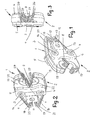
- the pressing tongs has two pressing jaws 1, 2 which are pivotable relative to one another and which are of the same design but are arranged rotated through 180 ° with respect to one another.
- Both pressing jaws 1, 2 are designed as two-armed levers which are pivotable about mutually parallel axes 3, 4. They are formed by screws, with which the pressing jaws 1, 2 are pivotally mounted between two tabs 5, 6. They have approximately quadrangular outline and are located on the opposite outer sides of the two pressing jaws 1, 2 at.
- the two tabs 5, 6 are advantageously the same design and provided on its one longitudinal side with a rounded recess 7, 8. It lies approximately half the length of the longitudinal side of the tabs 5, 6.
- a connecting tab 9, 10 from, the rectangular Outline has and is provided with an opening 11, 12.
- a (not shown) driving device can be connected, with which the pressing jaws 1, 2 can be pivoted in a manner to be described for the pressing operation against each other.
- the drive device is connected to a connecting bolt, which is inserted into the openings 11, 12 of the connecting lugs 9, 10, with the pressing tongs.
- This drive device can be driven, for example, hydraulically, pneumatically or by electric motor.
- the pressing jaws 1, 2 are, as in the 4 and 6 is shown for the pressing jaw 1, provided with a passage opening 13 through which the pivot axis 3 and 4 forming bolts is inserted, with which the pressing jaws 1, 2 are pivotally mounted between the tabs 5, 6.
- Each pressing jaw 1, 2 has the arms 14, 15 and 16, 17.
- the arms 14, 16 are tapered towards their free end.
- the arms 14, 16 have mutually facing flat inner surfaces 18, 19, the functional surfaces form, with which cooperates with the abutting connecting plates 9, 10 drive device during the pressing process.
- This drive device has an extendable plunger, at the end of which the pressing pliers facing the rollers are rotatably mounted, which reach the inner surfaces 18, 19 of the pressing jaws 1, 2 during extension of the plunger.
- the arms 14, 16 are pressed apart by the rollers, whereby the arms 15, 17 of the pressing jaws 1, 2 are pivoted in the direction of each other.
- the two arms 14, 16 by a (not shown) pressure spring loaded so that the arms 15, 17 in the direction of their in the Fig. 1 to 3 shown closed position are charged. This ensures that the crimping pliers are closed.
- the compression spring in the pressing tongs so that the two arms 15, 17 are pressure-loaded, so that the pressing tongs is always open. The workpieces to be pressed can then be easily inserted between the two arms 15, 17.
- the free ends of the arms 14, 16 are each provided with a connection 20, 21, which is advantageously designed as a passage opening.
- a manual drive device by means of a bolt or the like. Be connected.
- the manual drive device is designed in the manner of a pair of pliers and has two mutually pivotable two-armed lever.
- the short lever arms are connected to the terminals 20, 21, while the longer lever arms serve as operating arms. Since such manual drive devices are known, they are not explained in detail.
- the pressing tongs is thus designed so that either a driven or a manual drive device can be connected to them.
- the driven drive device is connected to the terminal lugs 9, 10 and the manual drive device to the terminals 20, 21.
- the arm 15 of the pressing jaw 1 is provided with a semicircular recess 22 which is bounded by a semicircular bottom 23. It extends over the width of the pressing jaw 1 and is semi-cylindrical. Depending on the pressing contour of the bottom 23 may also have a different shape, such as polygonal shape.
- the bottom 23 extends over an angular range of slightly smaller than 180 °. At both ends of the bottom 23 connects to planar side surfaces 24, 25, which are formed by the facing end faces of teeth 26, 27.
- the side surfaces 24, 25 are parallel to each other and parallel to a radial plane 28 which extends through the lowest point of the bottom 23 ( Fig. 4 ).
- the side surfaces 24, 25 extend beyond the axis of curvature 29 of the bottom 23.
- the teeth 26, 27 are aligned with each other.
- the teeth 26 are shorter than the teeth 27 and extend to the end face 30 of the pressing jaw 1.
- gaps 31, 32 are formed, in which engage the teeth 26, 27 of the pressing jaw 2.
- the interspaces 31, 32 are formed so that the teeth 26, 27 of the pressing jaws 1, 2 in the closed position with their side surfaces abut each other.
- the teeth 27 have a length such that these teeth even at maximum open pressing tongs ( Fig. 1 to 3 ) are not disengaged.
- the teeth 27, at least in their rear region form guide elements which ensure that the pressing jaws 1, 2 are exactly aligned with each other in each position, so that during the subsequent pressing operation no relative displacement of the pressing jaws 1, 2 in the direction of their pivot axes 3, 4 he follows. In this way it is ensured that the compression of the workpiece is flawless.
- the teeth 26, 27 advantageously have a rectangular cross-section, so that the teeth of the pressing jaws 1, 2 lie flat against one another over their entire height in the engaged position.
- the teeth 26, 27 of the two pressing jaws 1, 2 abut against the bottom 33, 34 of the intermediate spaces 31, 32.
- the pressing jaws 1, 2 surround the workpiece to be pressed over 180 °.
- the side surfaces 24, 25 of the teeth 26, 27 of the two pressing jaws 1, 2 each lie in a common plane, which runs parallel to the radial plane 28. Since the teeth 26, 27 of the two pressing jaws 1, 2 completely engage one another in this closed position of the pressing tongs and the width of the teeth corresponds to the width of the intermediate spaces 31, 32, a continuous side surface 24, 25 is formed.
- the pressed workpiece has a flawless, burr-free surface after the pressing process.
- the pressing jaw 1 is provided in the region of the arm 14 with a blind hole 35 into which one end of the Compressive spring is used, with which the two pressing jaws 1, 2 are loaded against each other.
- the pivoting of the pressing jaws 1, 2 is not very large, a relatively small length of the inner surface 18 is sufficient. It lies at an obtuse angle to a plane 36 containing the upper side of the teeth 26, 27 (FIG. Fig. 4 ). As a result, the pressing jaws 1, 2 can be made very compact, so that the pressing tongs are handy and have only low weight.
- To the inner surface 18 includes a part-circular recess 37, which connects the inner surface 18 with an inclined surface 38. In her is the blind hole 35th As is clear from the 4 to 6
- the inclined surface 38 is also at an obtuse angle to the plane 36.
- the inclined surface 38 may lie with the inner surface 18 in a common plane. In the exemplary embodiment, however, the inclined surface 38 is arranged offset relative to the inner surface 18 in the direction of the plane 36.
- the facing away from the recess 22 end face 39 of the teeth 27 is chamfered and is advantageously in the inclined surface 38.
- the engagement region of the teeth 27 is at the level of the tabs 5, 6, seen in Schwenkachscardi, thus covered by the tabs.
- the pressing tongs are characterized as a result of the training described by the fact that with her flawless, non-degree pressings are possible, the pressing tongs being characterized by a compact design and a low weight.
- the pressing tongs can be connected by the user either to a manual or to a driven drive device. This allows the pressing tongs to be used variably by the user. Since the two pressing jaws 1, 2 and also the tabs 5, 6 with the connecting lugs 9, 10 are each formed the same, is also a cost-effective production possible. The assembly of the pressing tongs is therefore very easy.
Landscapes
- Engineering & Computer Science (AREA)
- Mechanical Engineering (AREA)
- Press Drives And Press Lines (AREA)
- Manufacturing Of Electrical Connectors (AREA)
- Table Equipment (AREA)
Applications Claiming Priority (1)
| Application Number | Priority Date | Filing Date | Title |
|---|---|---|---|
| DE200710040895 DE102007040895A1 (de) | 2007-08-24 | 2007-08-24 | Presszange zum radialen Verpressen von Rohren, Rohrstücken und dergleichen |
Publications (3)
| Publication Number | Publication Date |
|---|---|
| EP2027971A2 true EP2027971A2 (fr) | 2009-02-25 |
| EP2027971A3 EP2027971A3 (fr) | 2010-08-04 |
| EP2027971B1 EP2027971B1 (fr) | 2013-11-27 |
Family
ID=40149687
Family Applications (1)
| Application Number | Title | Priority Date | Filing Date |
|---|---|---|---|
| EP08014576.6A Active EP2027971B1 (fr) | 2007-08-24 | 2008-08-16 | Pince de pression destinée à la compression radiale de tuyaux, éléments de tuyaux et analogues |
Country Status (3)
| Country | Link |
|---|---|
| EP (1) | EP2027971B1 (fr) |
| DE (1) | DE102007040895A1 (fr) |
| ES (1) | ES2447038T3 (fr) |
Cited By (3)
| Publication number | Priority date | Publication date | Assignee | Title |
|---|---|---|---|---|
| EP3205455A1 (fr) * | 2016-01-19 | 2017-08-16 | ProPress GmbH | Dispositif de presse |
| CN111279561A (zh) * | 2017-12-01 | 2020-06-12 | 伦斯泰格工具有限责任公司 | 压接口和具有两个钳口的压线钳 |
| CN112936891A (zh) * | 2018-01-09 | 2021-06-11 | 里奇工具公司 | 使模具轴向对齐的系统和方法 |
Families Citing this family (1)
| Publication number | Priority date | Publication date | Assignee | Title |
|---|---|---|---|---|
| USD1025732S1 (en) * | 2023-08-03 | 2024-05-07 | Qing Dai | Hydraulic tool |
Citations (7)
| Publication number | Priority date | Publication date | Assignee | Title |
|---|---|---|---|---|
| DE1452678A1 (de) | 1963-04-09 | 1969-03-06 | Hayden Nilos Ltd | Vorrichtung zum Kaltstauchen von Metallbandagen |
| US5267464A (en) | 1991-12-30 | 1993-12-07 | Cleland John G | Pipe ring crimping tool |
| DE20121845U1 (de) | 2001-01-15 | 2003-06-12 | Foell Remswerk | Preßzange |
| DE10354307A1 (de) | 2003-02-07 | 2004-08-19 | Gustav Klauke Gmbh | Verpressbackenpaar |
| EP1591176A1 (fr) | 2004-04-30 | 2005-11-02 | VIEGA GmbH & Co. KG. | Outil de sertissage de pièces |
| DE102005046333B3 (de) | 2005-09-27 | 2006-10-19 | Viega Gmbh & Co. Kg | Presswerkzeug |
| EP1731267A2 (fr) | 2005-06-10 | 2006-12-13 | M. Dubuis et Compagnie | Jeu de deux matrices destinées à équiper une presse à réteindre et/ou à sertir |
-
2007
- 2007-08-24 DE DE200710040895 patent/DE102007040895A1/de not_active Withdrawn
-
2008
- 2008-08-16 ES ES08014576T patent/ES2447038T3/es active Active
- 2008-08-16 EP EP08014576.6A patent/EP2027971B1/fr active Active
Patent Citations (7)
| Publication number | Priority date | Publication date | Assignee | Title |
|---|---|---|---|---|
| DE1452678A1 (de) | 1963-04-09 | 1969-03-06 | Hayden Nilos Ltd | Vorrichtung zum Kaltstauchen von Metallbandagen |
| US5267464A (en) | 1991-12-30 | 1993-12-07 | Cleland John G | Pipe ring crimping tool |
| DE20121845U1 (de) | 2001-01-15 | 2003-06-12 | Foell Remswerk | Preßzange |
| DE10354307A1 (de) | 2003-02-07 | 2004-08-19 | Gustav Klauke Gmbh | Verpressbackenpaar |
| EP1591176A1 (fr) | 2004-04-30 | 2005-11-02 | VIEGA GmbH & Co. KG. | Outil de sertissage de pièces |
| EP1731267A2 (fr) | 2005-06-10 | 2006-12-13 | M. Dubuis et Compagnie | Jeu de deux matrices destinées à équiper une presse à réteindre et/ou à sertir |
| DE102005046333B3 (de) | 2005-09-27 | 2006-10-19 | Viega Gmbh & Co. Kg | Presswerkzeug |
Cited By (3)
| Publication number | Priority date | Publication date | Assignee | Title |
|---|---|---|---|---|
| EP3205455A1 (fr) * | 2016-01-19 | 2017-08-16 | ProPress GmbH | Dispositif de presse |
| CN111279561A (zh) * | 2017-12-01 | 2020-06-12 | 伦斯泰格工具有限责任公司 | 压接口和具有两个钳口的压线钳 |
| CN112936891A (zh) * | 2018-01-09 | 2021-06-11 | 里奇工具公司 | 使模具轴向对齐的系统和方法 |
Also Published As
| Publication number | Publication date |
|---|---|
| DE102007040895A1 (de) | 2009-02-26 |
| EP2027971A3 (fr) | 2010-08-04 |
| ES2447038T3 (es) | 2014-03-11 |
| EP2027971B1 (fr) | 2013-11-27 |
Similar Documents
| Publication | Publication Date | Title |
|---|---|---|
| EP1649981B1 (fr) | Pince de sertissage | |
| EP1591176B1 (fr) | Outil de sertissage de pièces | |
| WO2014009083A1 (fr) | Outil de sertissage d'embouts | |
| EP4311627A2 (fr) | Mâchoires de pressage ainsi que pince de pressage avec deux mâchoires de serrage | |
| EP3718179B1 (fr) | Pince-étau | |
| EP3269509B1 (fr) | Pince pour réaliser de troux sur des profiles à section trapézoïdale | |
| EP2080592B1 (fr) | Anneau de serrage | |
| EP2027971B1 (fr) | Pince de pression destinée à la compression radiale de tuyaux, éléments de tuyaux et analogues | |
| EP3405314B1 (fr) | Cisaille à actionnement motorisé | |
| EP1892085B1 (fr) | Dispositif de presse | |
| EP1459825B1 (fr) | Outil pour couper les boulons ou les tiges, notamment les tiges filetées | |
| EP3580024B1 (fr) | Sécateur | |
| DE2146190A1 (de) | Gelenkmechanik für Werkzeuge u. dgl | |
| WO1990000098A1 (fr) | Presse radiale pour pieces sensiblement cylindriques | |
| DE202018105955U1 (de) | Crimpkopf und Crimpwerkzeug | |
| EP1952948B1 (fr) | Pince de sertissage | |
| EP1649948B1 (fr) | Outil de sertissage | |
| EP0611613B1 (fr) | Outil à sertir pour sertir un manchon cylindrique ou un manchon contenant un partie cylindrique | |
| DE10318508B4 (de) | Pressbackenhebelpaar für hydraulische oder elektrische Verpressgeräte | |
| DE19927776B4 (de) | Preßwerkzeug | |
| DE102010052447B4 (de) | Einsatz für eine Presse | |
| DE10044874A1 (de) | Schlüsselzange | |
| DE102006049447A1 (de) | Spannvorrichtung | |
| EP2774725B1 (fr) | Dispositif de presse | |
| DD222219B1 (de) | Vorrichtung zum abhaengen und verformen von drahtstuecken sowie austauschen eines kopfes |
Legal Events
| Date | Code | Title | Description |
|---|---|---|---|
| PUAI | Public reference made under article 153(3) epc to a published international application that has entered the european phase |
Free format text: ORIGINAL CODE: 0009012 |
|
| AK | Designated contracting states |
Kind code of ref document: A2 Designated state(s): AT BE BG CH CY CZ DE DK EE ES FI FR GB GR HR HU IE IS IT LI LT LU LV MC MT NL NO PL PT RO SE SI SK TR |
|
| AX | Request for extension of the european patent |
Extension state: AL BA MK RS |
|
| PUAL | Search report despatched |
Free format text: ORIGINAL CODE: 0009013 |
|
| AK | Designated contracting states |
Kind code of ref document: A3 Designated state(s): AT BE BG CH CY CZ DE DK EE ES FI FR GB GR HR HU IE IS IT LI LT LU LV MC MT NL NO PL PT RO SE SI SK TR |
|
| AX | Request for extension of the european patent |
Extension state: AL BA MK RS |
|
| 17P | Request for examination filed |
Effective date: 20110204 |
|
| AKX | Designation fees paid |
Designated state(s): DE ES FR IT |
|
| 17Q | First examination report despatched |
Effective date: 20120307 |
|
| GRAJ | Information related to disapproval of communication of intention to grant by the applicant or resumption of examination proceedings by the epo deleted |
Free format text: ORIGINAL CODE: EPIDOSDIGR1 |
|
| GRAP | Despatch of communication of intention to grant a patent |
Free format text: ORIGINAL CODE: EPIDOSNIGR1 |
|
| GRAP | Despatch of communication of intention to grant a patent |
Free format text: ORIGINAL CODE: EPIDOSNIGR1 |
|
| GRAP | Despatch of communication of intention to grant a patent |
Free format text: ORIGINAL CODE: EPIDOSNIGR1 |
|
| GRAP | Despatch of communication of intention to grant a patent |
Free format text: ORIGINAL CODE: EPIDOSNIGR1 |
|
| INTG | Intention to grant announced |
Effective date: 20130617 |
|
| GRAS | Grant fee paid |
Free format text: ORIGINAL CODE: EPIDOSNIGR3 |
|
| GRAA | (expected) grant |
Free format text: ORIGINAL CODE: 0009210 |
|
| RAP1 | Party data changed (applicant data changed or rights of an application transferred) |
Owner name: REMS GMBH & CO KG |
|
| AK | Designated contracting states |
Kind code of ref document: B1 Designated state(s): DE ES FR IT |
|
| REG | Reference to a national code |
Ref country code: DE Ref legal event code: R096 Ref document number: 502008011001 Country of ref document: DE Effective date: 20140123 |
|
| REG | Reference to a national code |
Ref country code: ES Ref legal event code: FG2A Ref document number: 2447038 Country of ref document: ES Kind code of ref document: T3 Effective date: 20140311 |
|
| REG | Reference to a national code |
Ref country code: DE Ref legal event code: R097 Ref document number: 502008011001 Country of ref document: DE |
|
| PLBE | No opposition filed within time limit |
Free format text: ORIGINAL CODE: 0009261 |
|
| STAA | Information on the status of an ep patent application or granted ep patent |
Free format text: STATUS: NO OPPOSITION FILED WITHIN TIME LIMIT |
|
| 26N | No opposition filed |
Effective date: 20140828 |
|
| REG | Reference to a national code |
Ref country code: DE Ref legal event code: R097 Ref document number: 502008011001 Country of ref document: DE Effective date: 20140828 |
|
| REG | Reference to a national code |
Ref country code: FR Ref legal event code: PLFP Year of fee payment: 9 |
|
| REG | Reference to a national code |
Ref country code: FR Ref legal event code: PLFP Year of fee payment: 10 |
|
| REG | Reference to a national code |
Ref country code: FR Ref legal event code: PLFP Year of fee payment: 11 |
|
| PGFP | Annual fee paid to national office [announced via postgrant information from national office to epo] |
Ref country code: FR Payment date: 20230620 Year of fee payment: 16 |
|
| PGFP | Annual fee paid to national office [announced via postgrant information from national office to epo] |
Ref country code: IT Payment date: 20230802 Year of fee payment: 16 Ref country code: ES Payment date: 20230904 Year of fee payment: 16 |
|
| P01 | Opt-out of the competence of the unified patent court (upc) registered |
Effective date: 20231115 |
|
| PGFP | Annual fee paid to national office [announced via postgrant information from national office to epo] |
Ref country code: DE Payment date: 20231027 Year of fee payment: 16 |