EP2027966B1 - Sample traveling stage with flexure mechanism module to absorb the deformation of the slide - Google Patents
Sample traveling stage with flexure mechanism module to absorb the deformation of the slide Download PDFInfo
- Publication number
- EP2027966B1 EP2027966B1 EP08013979A EP08013979A EP2027966B1 EP 2027966 B1 EP2027966 B1 EP 2027966B1 EP 08013979 A EP08013979 A EP 08013979A EP 08013979 A EP08013979 A EP 08013979A EP 2027966 B1 EP2027966 B1 EP 2027966B1
- Authority
- EP
- European Patent Office
- Prior art keywords
- slide
- sample
- flexure mechanism
- deformation
- traveling stage
- Prior art date
- Legal status (The legal status is an assumption and is not a legal conclusion. Google has not performed a legal analysis and makes no representation as to the accuracy of the status listed.)
- Active
Links
- 230000007246 mechanism Effects 0.000 title claims description 114
- 238000006073 displacement reaction Methods 0.000 claims description 16
- 238000005259 measurement Methods 0.000 claims description 5
- 239000011359 shock absorbing material Substances 0.000 claims description 2
- 238000004519 manufacturing process Methods 0.000 description 6
- 238000000034 method Methods 0.000 description 6
- 239000000463 material Substances 0.000 description 5
- 230000003139 buffering effect Effects 0.000 description 4
- 230000005484 gravity Effects 0.000 description 4
- 238000005381 potential energy Methods 0.000 description 4
- 229910001374 Invar Inorganic materials 0.000 description 3
- 239000006094 Zerodur Substances 0.000 description 3
- 238000009434 installation Methods 0.000 description 3
- 238000010521 absorption reaction Methods 0.000 description 2
- XAGFODPZIPBFFR-UHFFFAOYSA-N aluminium Chemical compound [Al] XAGFODPZIPBFFR-UHFFFAOYSA-N 0.000 description 2
- 229910052782 aluminium Inorganic materials 0.000 description 2
- 230000007423 decrease Effects 0.000 description 2
- 238000002438 flame photometric detection Methods 0.000 description 2
- 238000007689 inspection Methods 0.000 description 2
- 238000011084 recovery Methods 0.000 description 2
- 239000004065 semiconductor Substances 0.000 description 2
- 229910000838 Al alloy Inorganic materials 0.000 description 1
- 238000004364 calculation method Methods 0.000 description 1
- 230000000052 comparative effect Effects 0.000 description 1
- 230000000694 effects Effects 0.000 description 1
- 230000002787 reinforcement Effects 0.000 description 1
Images


Classifications
-
- H—ELECTRICITY
- H01—ELECTRIC ELEMENTS
- H01L—SEMICONDUCTOR DEVICES NOT COVERED BY CLASS H10
- H01L21/00—Processes or apparatus adapted for the manufacture or treatment of semiconductor or solid state devices or of parts thereof
- H01L21/67—Apparatus specially adapted for handling semiconductor or electric solid state devices during manufacture or treatment thereof; Apparatus specially adapted for handling wafers during manufacture or treatment of semiconductor or electric solid state devices or components ; Apparatus not specifically provided for elsewhere
- H01L21/68—Apparatus specially adapted for handling semiconductor or electric solid state devices during manufacture or treatment thereof; Apparatus specially adapted for handling wafers during manufacture or treatment of semiconductor or electric solid state devices or components ; Apparatus not specifically provided for elsewhere for positioning, orientation or alignment
- H01L21/681—Apparatus specially adapted for handling semiconductor or electric solid state devices during manufacture or treatment thereof; Apparatus specially adapted for handling wafers during manufacture or treatment of semiconductor or electric solid state devices or components ; Apparatus not specifically provided for elsewhere for positioning, orientation or alignment using optical controlling means
-
- B—PERFORMING OPERATIONS; TRANSPORTING
- B23—MACHINE TOOLS; METAL-WORKING NOT OTHERWISE PROVIDED FOR
- B23Q—DETAILS, COMPONENTS, OR ACCESSORIES FOR MACHINE TOOLS, e.g. ARRANGEMENTS FOR COPYING OR CONTROLLING; MACHINE TOOLS IN GENERAL CHARACTERISED BY THE CONSTRUCTION OF PARTICULAR DETAILS OR COMPONENTS; COMBINATIONS OR ASSOCIATIONS OF METAL-WORKING MACHINES, NOT DIRECTED TO A PARTICULAR RESULT
- B23Q2210/00—Machine tools incorporating a specific component
- B23Q2210/002—Flexures
-
- G—PHYSICS
- G01—MEASURING; TESTING
- G01R—MEASURING ELECTRIC VARIABLES; MEASURING MAGNETIC VARIABLES
- G01R31/00—Arrangements for testing electric properties; Arrangements for locating electric faults; Arrangements for electrical testing characterised by what is being tested not provided for elsewhere
- G01R31/28—Testing of electronic circuits, e.g. by signal tracer
- G01R31/2851—Testing of integrated circuits [IC]
- G01R31/2893—Handling, conveying or loading, e.g. belts, boats, vacuum fingers
Definitions
- the present invention relates to a sample traveling stage with a flexure mechanism module to absorb the deformation of the slide.
- the present invention relates to a sample traveling stage to be used for inspection equipment or precision processing equipment for semiconductors or FPDs, (Flat Panel Displays), and, in particular, relates to a sample traveling stage with a flexure mechanism to absorb the deformation of the slide in order to improve measuring accuracy by protecting against the deformation, which occurs as a result of the slide of the sample traveling stage, being delivered to the sample table.
- a sample traveling stage is an equipment item used for loading, travel measuring, and/or processing an object (or sample, used for inspection equipment or precision processing equipment of semiconductors or FPDs to a desired location; and it is used for a laser displacement measuring system to analyze the displacement signal with the signal measured by the interference between the incident laser beam to the mirror and the reflected laser beam by the mirror.
- sample traveling stage (100) has a main body part that includes X, Y slide (113, 114) guided by X, Y guide (111, 112) in a mutual crossing direction, sample table (116) mounted on the above Y slide (114) and moving sample (115), and the X, Y bar mirror attached to the above sample table (116) in a mutually vertical direction.
- a measuring part includes an interferometer (133) to diffuse the X, Y beam, which is output at laser head (131) after being mounted on the operating path of the above main body part and divided through beam divider (132), by the above X, Y bar mirror (117, 118), and X, Y receiver (134) so as to convert the interference signal, which is reflected by the above X, Y bar mirror (117, 118), into a displacement signal.
- interferometer to diffuse the X, Y beam, which is output at laser head (131) after being mounted on the operating path of the above main body part and divided through beam divider (132), by the above X, Y bar mirror (117, 118), and X, Y receiver (134) so as to convert the interference signal, which is reflected by the above X, Y bar mirror (117, 118), into a displacement signal.
- the sample position measurement by sample traveling stage (100) has a structure measured by the interference between X, Y bar mirror (117, 118) fixed to the above sample table (116) and the laser beam reflected by the X, Y bar mirror (117, 118), the problem in which relative displacement between the above X, Y bar mirror (117, 118) and the above sample (115) must be maintained regularly, needs to be resolved previously in order to measure the correct position of the above sample (115).
- sample table (116) of sample traveling stage (100) can be deformed due to the following reasons.
- slide (113, 114) is subject to a processing error of guide part (111, 112) or an error in terms of linearity and flatness.
- the deformation degree is different due to differences in the thermal expansion coefficient between slide (113, 114) and sample table (116), and, particularly, in cases where slide (113, 114) and sample table (116) are subject to connecting tools such as a bolt, problems relating to the deformation of slide (113, 114) occur as it is delivered to sample table (116).
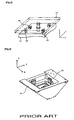
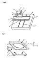
- US 2003/0020225 A1 describes a configuration in which deformation of slide (114) would not be imparted to sample table (116) by mounting three deformation preventing devices (150) having a motion free angle at the X, Y direction at the space between slide (114) and sample table (116).
- US 2003/0020225 A1 additionally describes flexure mechanism (160) to restrict the motion in the X, Y direction in order to prevent the low strength in the X, Y direction of deformation preventing mechanism (150).
- the configuration in which the deformation of slide (114) would not be delivered to sample table (116) is provided by configuring three buffering mechanisms (170) fixed with sample table (116) at the upper side of slide (114), and by permitting only a free angle toward the radius direction to become more distant from the center of the thermal expansion direction with the restriction of six free angles by the above buffering mechanism (170).
- sample traveling stage (100) as illustrated in Figure 4 has difficulties in terms of processing and assembly for buffering mechanism (170), and a height difference between sample table (116) and slide (114) occurs due to the height of buffering mechanism (170).
- This not only makes the weight center of the drive unit for sample traveling stage high, but also reduces control stability because this makes the offset between the point at which the drive force operates and the actual weight center.
- Invar or Zerodur for the above slide (113, 114) and sample table (116) are used for a single body so as to resolve the above problems.
- this use has certain problems.
- the cost of Invar or Zerodur is at least ten times that of aluminum, and processing costs also increase because of poor workability levels.
- a further sample traveling stage is known from US 5,101,301 .
- the above discussed problems are partially solved in the embodiment disclosed in Figs. 17 - 20 by arranging elastic members in depressions of an Y-table.
- Example embodiments of the present invention address the aforementioned problems and provide a sample traveling stage using a flexure mechanism module for slide deformation absorption, so as to prevent the deformation of the slide from being delivered to the sample table by the configuration of the flexure mechanism module for protecting the delivery of the reduced structure deformation of the upper structure, forming it into one body at the slide of the sample traveling stage, or combining it through the bolt connection at the slide area.
- a sample traveling stage includes: a movable part including a first slide and a second slide arranged in a mutually crossing direction, the first slide mounted on a base frame and movable along a first guide block, the second slide mounted on the fist slide and movable along a second guide block; and a traveling part including a sample table configured to travel a sample, the sample table connected to the second slide by a flexure mechanism module.
- the flexure mechanism module may include a plurality of shock-absorbing holes that penetrate an upper side of the second slide along a vertical direction regularly at certain intervals and a plurality of deformation lines that meet at centers of the shock-absorbing holes, and the flexure mechanism module may be configured to provide a deformation space of a bridge part and a mounting part and to absorb slide deformations.
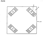
- a flexure mechanism module adapted to absorb slide deformation may be provided at each of four corners of the second slide.
- a flexure mechanism module adapted to absorb slide deformation may be provided at two corners of one side and a second of another side of the second slide.
- At least five flexure mechanism modules may be provided on the second slide one of (a) symmetrically and (b) asymmetrically.
- An upper side of the mounting part may include a shock-absorbing material in contact with the sample table.
- a contact area of the mounting part and the bridge part may have at least one of (a) linear shape, (b) a semi-circular shape, and (c) an elliptical shape.
- the flexure mechanism module may be connected to the second slide.
- the traveling part may include X- and Y-bar mirrors mounted on the sample table.
- the sample traveling stage may include a measurement part including a laser head, a beam divider, and an interferometer arranged in an operating path of the movable part, and the measurement part may be configured to output a displacement signal by reception from a receiver of an input beam interference signal reflected by the X- and Y-bar mirrors.
- the sample traveling stage using the flexure mechanism module for slide deformation of the slide absorption provides the following effects with the methods of configuring the flexure mechanism by one body to the second slide configured on the sample traveling stage, or by combining the manufactured flexure mechanism module to the slide area.
- Measuring accuracy may improve because the deformation error of the mirror and the sample, including the sample table, decreases due to the non-delivery to the sample table of the deformation by the slide.
- Productivity may improve due to the minimization of the error rate because the accuracy of sample manufacturing improves.
- manufacturing costs for components may decrease because it is possible to form the slide and flexure mechanism as one body during the manufacturing process of the sample traveling stage, and high productivity levels can be achieved because high-speed motion and high control stability is achieved due to the comparative lowering of the center of gravity.
- material costs including those for the slide, can be reduced because, general, aluminum or an aluminum alloy can replace costly materials such as Invar or Zerodur during the manufacturing process of the sample traveling stage, and manufacturing costs also can be saved because the workability of components is improved.
- Figures 5 and 6 illustrate assembled and disassembled states of the sample traveling stage
- Figure 7 illustrates the flexure mechanism module for the sample traveling stage according to example embodiments of the present invention
- Figures 8a , 8b , 9a , and 9b illustrate the installation state and deformation state of the flexure mechanism
- Figure 10 illustrates a flexure mechanism module according to example embodiments of the present invention.
- a moving part is provided in which a first slide (20), which is mounted on base frame (10) and moves along first guide block (21), and second slide (30), which is mounted on the first slide (20) and moves along second guide block (32), are installed in a mutually crossing direction.
- a traveling part travels sample (41) through sample table (40) connected to the flexure mechanism (50) provided on the second slide (30), and measures displacement through X, Y bar mirror (42, 43) installed at the sample table (40) in a mutually vertical direction.
- a measuring part includes a laser head (61), beam divider (62), and interferometer (63) installed at the operating path of the moving part, and outputs a displacement signal by receiving the input beam interference signal reflected by the X, Y bar mirror (42, 43) from receiver (64).
- Sample traveling stage (1) in these examples includes a moving part to perform a reciprocal motion in the X axis and Y axis direction of the installed place, a traveling part to be mounted on the moving part and to convey measuring/processing object (41), or sample, and a measuring part to measure the position of sample (41), which is conveyed by the moving part, with a laser beam.
- the moving part is mounted on base frame (10) and performs a reciprocal motion in the X and Y axis direction according to the external signal.
- the moving part is attached in the direction that first slide (20) and second slide (30), which are mounted on base frame (10), cross mutually.
- First slide (20) is mounted on base frame (10), e.g., on a pair of guide rails (11) attached to the upper center of base frame (10) in parallel and at regular intervals, and performs a reciprocal motion in the X axis direction to move second guide block (32) connected to guide rail (31).
- Second slide (30) is mounted on base frame (10), e.g., on a pair of guide rails (31) attached to the upper sides of first slide (20) in parallel and at regular intervals, and performs a reciprocal motion in the Y axis direction to move second guide block (32) connected to guide rail (31).
- Traveling part is an object mounted on second slide (30) to convey sample (41), and includes sample table (40), which is mounted on second slide (30), whereby the sample is laid on the upper side, and flexure mechanism module (50), which is interposed between the sample table (40) and second slide (30), and absorbs the deformation of the second slide (30).
- Sample table (40) is an object that performs a reciprocal motion by first slide (20) and second slide (30).
- X bar mirror (42) and Y bar mirror (43) measure the displacement of the laser beam attached on its upper side in a vertical direction.
- Connecting holes are provided in second slide (30) and sample table (40), and are used during the connecting process of sample table (40).
- Flexure mechanism module (50) is an object arranged at the upper side of second slide (30) and prevents the deformation of second slide (30) from being delivered or imparted to sample table (40).
- a flexure mechanism arranged at the flexure mechanism module deforms in the short axis direction as illustrated in Figure 11 , and maintains the shape of the sample table before the deformation of the slide during the deformation of the slide.
- each flexure mechanism area of flexure mechanism module (50) is formed so that it may deform within a small range in the short axis direction, and, in particular, be manufactured with various kinds and shapes considering the workability properties and deformation shape of the flexure mechanism.
- flexure mechanism (50) includes several shock-absorbing holes (53) penetrated regularly at the upper side of the second slide (30) at regular intervals according to the upper and lower directions, several deforming lines (54), which are cut to meet the center of the shock-absorbing holes (53), and which provide a deforming space of bridge part (56) and mounting part (52) on which the sample table (40) is mounted.
- One or more bridge part(s) (56) may be formed at both sides of mounting parts (52) into one body.
- Connecting holes (51) formed at mounting part (52) are provided by the use of connecting tools, such as the sample table (40) and bolts.
- Shock-absorbing holes may be processed so as to be at accurate positions and of accurate sizes, and the deforming lines (54) may be processed by wire-EDM in order to meet the positions of shock-absorbing holes (53).
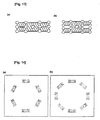
- the flexure mechanism may be configured according to various types, such as a plate spring type flexure mechanism, which forms the contacting surface of mounting part and bridge part into linear shapes, as illustrated in Figure 12a , a right circular hinge flexure mechanism, which forms the contacting surface of mounting part and bridge part into semi-circular shapes, as illustrated in Figure 12b , a corner filleted hinge flexure mechanism, which forms a contacting surface of mounting part and bridge part into shapes, as illustrated in Figure 12c , and an elliptical hinge flexure mechanism, which forms a contacting surface of mounting part and bridge part into ellipses, as illustrated in Figure 12d , etc.
- a plate spring type flexure mechanism which forms the contacting surface of mounting part and bridge part into linear shapes, as illustrated in Figure 12a
- a right circular hinge flexure mechanism which forms the contacting surface of mounting part and bridge part into semi-circular shapes
- a corner filleted hinge flexure mechanism which forms a contacting surface of mounting part and bridge part into shapes
- a plate spring type flexure mechanism can create large displacement levels, but has the disadvantage whereby the strength of the direction beside the axes permitting deformation is comparatively weak.
- the right circular hinge flexure mechanism has the advantage of adequate axis strength properties, although deformation levels are comparatively small.
- Figures 13 and 13b illustrate an example of a shape using a right circular hinge flexure mechanism, which can change in a short axis direction through a four-bar linkage.
- a more complicated mechanism may be provided, although the processing of the four-bar mechanism may be simplest.
- Flexure mechanism (50) can be arranged on the flexure mechanism module in order to prevent the deformation of the slide from being delivered to the sample table.
- the flexure mechanism of which the deformation of the short axis direction is permitted so as to restrict three free angles on the plane, is available from at least three units. More units may be provided.
- three flexure mechanisms may be provided, e.g., at both corners of one side and at the center of the other side of second slide (30) as illustrated in Figures 9a and 9b , or four flexure mechanisms may be arranged at four corners of second slide (30) as illustrated in Figures 8a and 8b .
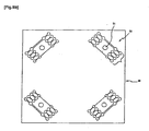
- flexure mechanisms can be arranged into a flexure mechanism module as illustrated in Figures 14a and 14b .
- the arrangement of the flexure mechanism does not need to be symmetrical, e.g., five or seven units may be arranged asymmetrically, and heat deformation delivery to the sample table can be prevented.
- Flexure mechanism (50) can be formed by one body on the second slide (30), but it can also be formed and connected by an extra member.
- measuring part (60) measures the position of sample (41) which is mounted on sample table (40) and traveled by the laser beam, and includes of laser head (61), which is attached to the moving path of first and second slides (20, 30), and outputs the laser beam, beam divider (62) which divides the laser beam output from the laser head (61) into the X beam and Y beam, interferometer (63), which outputs the beam divided by two parts by the beam divider (62) into X bar mirror (42) and Y bar mirror (43) and X, Y receiver (64), which transforms the beam into a displacement signal by receiving the interference signal reflected by the X, Y receiver (42, 43).
- laser head 61
- beam divider (62) which divides the laser beam output from the laser head (61) into the X beam and Y beam
- interferometer (63) which outputs the beam divided by two parts by the beam divider (62) into X bar mirror (42) and Y bar mirror (43) and X, Y receiver (64), which transforms the beam into a
- sample position (41) is measured by measuring part, in that the X direction displacement of sample table (40) is measured by X bar mirror (42), and the Y direction displacement is measured by Y bar mirror (43).
- the interference signal of interferometer (63) is measured by receiver (64) of the measuring part, and is transformed into a displacement signal after the signal processing process.
- first slide and second slide (20, 30) are deformed by excessive connection or heat expansion, the deformation of second slide (30) is delivered to sample table (40) by being absorbed through flexure mechanism (50).
- shock-absorbing holes (53) or deformation line (54) of flexure mechanism (50) deforms to the extent of the corresponding deformation level of second slide (30) and absorbs the deformation of second slide (30).
- the flexure mechanism hinge part may be implemented in order to prevent the heat expansion of the slide part in the event of a temperature change.
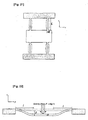
- FIG 15 the appearance of the slide part, which fixes the sample table through a bolt connection in general, is illustrated.
- the slide part is deformed.
- the part indicated by a full line shows the slide appearance before deformation; and the part indicated by the dotted line shows the slide appearance after being expanded by heat.
- a a heat expansion coefficient of material
- E an elastic rate of material
- A a cross-section of the connecting part
- d the diameter of the connecting bolt
- b the thickness of the slide part
- L the distance from the center of the slide to the connecting part
- ⁇ L the deforming degree by which the connecting part is expanded by heat deformation.
- the tolerance of the flexure mechanism deformation by heat expansion force should be over ⁇ L.
- the maximum stress to be loaded on the hinge of the flexure mechanism should be less than the yield strength, because yield phenomena should not occur despite the tolerable deformation degree of the flexure mechanism becoming ⁇ L.
- the strength of the single flexure mechanism should be calculated so as to estimate the deforming degree of a flexure mechanism by heat expansion force F.
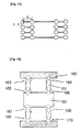
- Figure 18 For ease of understanding, the appearance of a single flexure mechanism is illustrated in Figure 18 . Although the appearance of the instrumental parts illustrated in Figures 17 and 18 differ from each other, the structure and mechanism are the same.
- the single flexure instrumental part is consisted according to the following.
- Reference numeral 160 represents the fixed part to the slide part or slide
- reference numeral 162 represents a fixing part for the sample table
- reference numeral 161 corresponds to a link part to connect the slide part and the fixing part
- reference numerals 163 to 170 represent eight hinges having a rotary free angle.
- Figure 19 the phenomenon whereby a single flexure mechanism deforms is illustrated in Figure 19 .
- V 1 2 ⁇ k ⁇ ⁇ ⁇ ⁇ x l 2
- the worst condition refers to the case in which beams of the flexure mechanism include the same sectional area as the hinge and the indented area illustrated in Figure 7 . In this regard, reference is made to Figure 21 .
- the total sum of the fixing part mass of the flexure mechanism mount is the mass of the sample test to be fixed to the upper area and the mass of the mirror and the sample.
- the weight which is dispersed to four flexure mechanisms equally, can be regarded as a force equal to Mg/4 in the gravity direction on the fixing part of the single flexure mechanism.
- the sink phenomenon of the flexure mechanism is the same as illustrated in Figure 8 .
Landscapes
- Engineering & Computer Science (AREA)
- Physics & Mathematics (AREA)
- Condensed Matter Physics & Semiconductors (AREA)
- General Physics & Mathematics (AREA)
- Manufacturing & Machinery (AREA)
- Computer Hardware Design (AREA)
- Microelectronics & Electronic Packaging (AREA)
- Power Engineering (AREA)
- Container, Conveyance, Adherence, Positioning, Of Wafer (AREA)
- Testing Or Measuring Of Semiconductors Or The Like (AREA)
- Length Measuring Devices By Optical Means (AREA)
- Details Of Measuring And Other Instruments (AREA)
Applications Claiming Priority (2)
| Application Number | Priority Date | Filing Date | Title |
|---|---|---|---|
| KR20070083496 | 2007-08-20 | ||
| KR1020080005417A KR100973530B1 (ko) | 2007-08-20 | 2008-01-17 | 슬라이드변형흡수용 유연기구모듈을 이용한 시편이송장치 |
Publications (2)
| Publication Number | Publication Date |
|---|---|
| EP2027966A1 EP2027966A1 (en) | 2009-02-25 |
| EP2027966B1 true EP2027966B1 (en) | 2010-04-21 |
Family
ID=39884190
Family Applications (1)
| Application Number | Title | Priority Date | Filing Date |
|---|---|---|---|
| EP08013979A Active EP2027966B1 (en) | 2007-08-20 | 2008-08-05 | Sample traveling stage with flexure mechanism module to absorb the deformation of the slide |
Country Status (3)
| Country | Link |
|---|---|
| US (1) | US7821632B2 (enExample) |
| EP (1) | EP2027966B1 (enExample) |
| JP (1) | JP5435909B2 (enExample) |
Families Citing this family (6)
| Publication number | Priority date | Publication date | Assignee | Title |
|---|---|---|---|---|
| US20110090563A1 (en) * | 2008-04-11 | 2011-04-21 | Molecular Devices, Inc. | Uniformity in slide scanning |
| JP5911959B2 (ja) | 2011-09-09 | 2016-04-27 | マッパー・リソグラフィー・アイピー・ビー.ブイ. | ウェーハテーブル用支持構造体 |
| JP6274246B2 (ja) * | 2016-04-08 | 2018-02-07 | 株式会社デンソー | 監視装置 |
| CN106002312B (zh) * | 2016-06-29 | 2018-01-23 | 广东工业大学 | 一种单驱动刚柔耦合精密运动平台及其实现方法及应用 |
| JP7178944B2 (ja) * | 2019-04-09 | 2022-11-28 | 株式会社ニューフレアテクノロジー | ステージ装置 |
| CN112964191B (zh) * | 2021-03-25 | 2022-11-04 | 四川合众精准科技有限公司 | 一种微变形激光准直测量方法 |
Family Cites Families (14)
| Publication number | Priority date | Publication date | Assignee | Title |
|---|---|---|---|---|
| JPS6335989U (enExample) | 1986-08-25 | 1988-03-08 | ||
| JP2711589B2 (ja) * | 1990-09-13 | 1998-02-10 | キヤノン株式会社 | レーザ干渉計用ミラーの取付け方法及び該方法を用いたステージ装置 |
| JP3160049B2 (ja) * | 1992-03-12 | 2001-04-23 | 株式会社日立製作所 | 位置決め装置 |
| JPH09320954A (ja) * | 1996-05-31 | 1997-12-12 | Nikon Corp | ステージ装置 |
| JP3678533B2 (ja) * | 1997-04-10 | 2005-08-03 | 富士通株式会社 | 荷電粒子ビーム露光装置 |
| JPH11154698A (ja) | 1997-11-21 | 1999-06-08 | Nikon Corp | テーブル支持装置 |
| JPH11295031A (ja) * | 1998-04-08 | 1999-10-29 | Canon Inc | 位置決めステージ装置とその位置計測方法および位置決めステージ装置を備えた露光装置ならびにデバイス製造方法 |
| JP3413122B2 (ja) * | 1998-05-21 | 2003-06-03 | キヤノン株式会社 | 位置決め装置及びこれを用いた露光装置並びにデバイス製造方法 |
| JP2001274223A (ja) | 2000-03-23 | 2001-10-05 | Hitachi Ltd | 移動テーブル装置 |
| JP2002022868A (ja) * | 2000-07-07 | 2002-01-23 | Sumitomo Heavy Ind Ltd | X−yステージの可動テーブルの支持構造 |
| CN100401193C (zh) * | 2002-07-11 | 2008-07-09 | Asml荷兰有限公司 | 光刻装置及制造集成电路的方法 |
| KR100497729B1 (ko) * | 2003-02-21 | 2005-06-28 | 한국과학기술원 | 유연기구 메커니즘을 이용한 3축 직선운동 스테이지 |
| US7384228B2 (en) * | 2004-05-24 | 2008-06-10 | Asml Netherlands B.V. | Insertion device, lithographic apparatus with said insertion device and device manufacturing method |
| US20080111977A1 (en) * | 2006-11-14 | 2008-05-15 | Asml Holding N.V. | Compensation techniques for fluid and magnetic bearings |
-
2008
- 2008-08-05 EP EP08013979A patent/EP2027966B1/en active Active
- 2008-08-06 US US12/186,712 patent/US7821632B2/en active Active
- 2008-08-19 JP JP2008210611A patent/JP5435909B2/ja not_active Expired - Fee Related
Also Published As
| Publication number | Publication date |
|---|---|
| US7821632B2 (en) | 2010-10-26 |
| JP2009065147A (ja) | 2009-03-26 |
| US20090051911A1 (en) | 2009-02-26 |
| EP2027966A1 (en) | 2009-02-25 |
| JP5435909B2 (ja) | 2014-03-05 |
Similar Documents
| Publication | Publication Date | Title |
|---|---|---|
| EP2027966B1 (en) | Sample traveling stage with flexure mechanism module to absorb the deformation of the slide | |
| EP2820376B1 (en) | Coordinate measuring machine with support beam having springs | |
| US7429705B2 (en) | Parallel-guiding mechanism for compact weighing system | |
| US4852267A (en) | Coordinate measuring machine having a guide section for a column of a measuring member support body | |
| JP2015516551A (ja) | エネルギーガイドチェーンと、これに用いる引張力・圧縮力監視システムと、これに用いる接続部材 | |
| EP2472216A1 (en) | Co-ordinate measuring machine | |
| US6880409B2 (en) | Curved panel shear test apparatus | |
| CN105627875A (zh) | 长度测量装置 | |
| CN113334096B (zh) | 龙门滑台柔性铰链支撑组件及其龙门双驱装置 | |
| CN101509792B (zh) | 用于吸收滑轨变形的具有柔性机构模块的样品运送平台 | |
| CN114923617B (zh) | 一种发动机升力测量装置 | |
| EP1462758A2 (en) | Method and device for attaching an elastic fixture to a length measuring device. | |
| EP0706035A2 (en) | Top pan balance | |
| EP1659373B1 (en) | Linear encoder with temperature compensation | |
| CN109140146B (zh) | 一种基于柔性铰链的高精度升降平台 | |
| CA3049294A1 (en) | Bidirectional measuring head for dimensional and/or geometric checking of a mechanical piece | |
| KR102608430B1 (ko) | 교량 탄성 받침의 안전진단용 변위 측정 장치 | |
| CN211346629U (zh) | 一种动车车钩中心高度的测量工具 | |
| TWI605203B (zh) | 交叉滾子導引組件及具有交叉滾子導引元件之切割裝置 | |
| CN220230337U (zh) | 横梁检测工装 | |
| CN222597226U (zh) | 一种龙门三坐标测量机 | |
| CN223243520U (zh) | 测量装置 | |
| CN110043560A (zh) | 三维直线滚动导轨 | |
| EP4392189B1 (en) | Bending machine, in particular a press brake, with a position measuring system | |
| CN217980201U (zh) | 一种改进尺身结构的光栅尺 |
Legal Events
| Date | Code | Title | Description |
|---|---|---|---|
| PUAI | Public reference made under article 153(3) epc to a published international application that has entered the european phase |
Free format text: ORIGINAL CODE: 0009012 |
|
| AK | Designated contracting states |
Kind code of ref document: A1 Designated state(s): AT BE BG CH CY CZ DE DK EE ES FI FR GB GR HR HU IE IS IT LI LT LU LV MC MT NL NO PL PT RO SE SI SK TR |
|
| AX | Request for extension of the european patent |
Extension state: AL BA MK RS |
|
| AKX | Designation fees paid |
Designated state(s): AT BE BG CH CY CZ DE DK EE ES FI FR GB GR HR HU IE IS IT LI LT LU LV MC MT NL NO PL PT RO SE SI SK TR |
|
| 17P | Request for examination filed |
Effective date: 20090825 |
|
| GRAP | Despatch of communication of intention to grant a patent |
Free format text: ORIGINAL CODE: EPIDOSNIGR1 |
|
| GRAS | Grant fee paid |
Free format text: ORIGINAL CODE: EPIDOSNIGR3 |
|
| GRAA | (expected) grant |
Free format text: ORIGINAL CODE: 0009210 |
|
| AK | Designated contracting states |
Kind code of ref document: B1 Designated state(s): AT BE BG CH CY CZ DE DK EE ES FI FR GB GR HR HU IE IS IT LI LT LU LV MC MT NL NO PL PT RO SE SI SK TR |
|
| REG | Reference to a national code |
Ref country code: GB Ref legal event code: FG4D |
|
| REG | Reference to a national code |
Ref country code: CH Ref legal event code: EP |
|
| REG | Reference to a national code |
Ref country code: IE Ref legal event code: FG4D |
|
| REF | Corresponds to: |
Ref document number: 602008001039 Country of ref document: DE Date of ref document: 20100602 Kind code of ref document: P |
|
| REG | Reference to a national code |
Ref country code: CH Ref legal event code: NV Representative=s name: ICB INGENIEURS CONSEILS EN BREVETS SA |
|
| REG | Reference to a national code |
Ref country code: NL Ref legal event code: VDEP Effective date: 20100421 |
|
| LTIE | Lt: invalidation of european patent or patent extension |
Effective date: 20100421 |
|
| PG25 | Lapsed in a contracting state [announced via postgrant information from national office to epo] |
Ref country code: SE Free format text: LAPSE BECAUSE OF FAILURE TO SUBMIT A TRANSLATION OF THE DESCRIPTION OR TO PAY THE FEE WITHIN THE PRESCRIBED TIME-LIMIT Effective date: 20100421 Ref country code: NO Free format text: LAPSE BECAUSE OF FAILURE TO SUBMIT A TRANSLATION OF THE DESCRIPTION OR TO PAY THE FEE WITHIN THE PRESCRIBED TIME-LIMIT Effective date: 20100721 Ref country code: NL Free format text: LAPSE BECAUSE OF FAILURE TO SUBMIT A TRANSLATION OF THE DESCRIPTION OR TO PAY THE FEE WITHIN THE PRESCRIBED TIME-LIMIT Effective date: 20100421 Ref country code: LT Free format text: LAPSE BECAUSE OF FAILURE TO SUBMIT A TRANSLATION OF THE DESCRIPTION OR TO PAY THE FEE WITHIN THE PRESCRIBED TIME-LIMIT Effective date: 20100421 Ref country code: ES Free format text: LAPSE BECAUSE OF FAILURE TO SUBMIT A TRANSLATION OF THE DESCRIPTION OR TO PAY THE FEE WITHIN THE PRESCRIBED TIME-LIMIT Effective date: 20100801 |
|
| PG25 | Lapsed in a contracting state [announced via postgrant information from national office to epo] |
Ref country code: SI Free format text: LAPSE BECAUSE OF FAILURE TO SUBMIT A TRANSLATION OF THE DESCRIPTION OR TO PAY THE FEE WITHIN THE PRESCRIBED TIME-LIMIT Effective date: 20100421 Ref country code: FI Free format text: LAPSE BECAUSE OF FAILURE TO SUBMIT A TRANSLATION OF THE DESCRIPTION OR TO PAY THE FEE WITHIN THE PRESCRIBED TIME-LIMIT Effective date: 20100421 Ref country code: HR Free format text: LAPSE BECAUSE OF FAILURE TO SUBMIT A TRANSLATION OF THE DESCRIPTION OR TO PAY THE FEE WITHIN THE PRESCRIBED TIME-LIMIT Effective date: 20100421 Ref country code: AT Free format text: LAPSE BECAUSE OF FAILURE TO SUBMIT A TRANSLATION OF THE DESCRIPTION OR TO PAY THE FEE WITHIN THE PRESCRIBED TIME-LIMIT Effective date: 20100421 Ref country code: IS Free format text: LAPSE BECAUSE OF FAILURE TO SUBMIT A TRANSLATION OF THE DESCRIPTION OR TO PAY THE FEE WITHIN THE PRESCRIBED TIME-LIMIT Effective date: 20100821 Ref country code: LV Free format text: LAPSE BECAUSE OF FAILURE TO SUBMIT A TRANSLATION OF THE DESCRIPTION OR TO PAY THE FEE WITHIN THE PRESCRIBED TIME-LIMIT Effective date: 20100421 |
|
| PG25 | Lapsed in a contracting state [announced via postgrant information from national office to epo] |
Ref country code: PL Free format text: LAPSE BECAUSE OF FAILURE TO SUBMIT A TRANSLATION OF THE DESCRIPTION OR TO PAY THE FEE WITHIN THE PRESCRIBED TIME-LIMIT Effective date: 20100421 Ref country code: CY Free format text: LAPSE BECAUSE OF FAILURE TO SUBMIT A TRANSLATION OF THE DESCRIPTION OR TO PAY THE FEE WITHIN THE PRESCRIBED TIME-LIMIT Effective date: 20100609 |
|
| PG25 | Lapsed in a contracting state [announced via postgrant information from national office to epo] |
Ref country code: DK Free format text: LAPSE BECAUSE OF FAILURE TO SUBMIT A TRANSLATION OF THE DESCRIPTION OR TO PAY THE FEE WITHIN THE PRESCRIBED TIME-LIMIT Effective date: 20100421 Ref country code: EE Free format text: LAPSE BECAUSE OF FAILURE TO SUBMIT A TRANSLATION OF THE DESCRIPTION OR TO PAY THE FEE WITHIN THE PRESCRIBED TIME-LIMIT Effective date: 20100421 |
|
| PLBE | No opposition filed within time limit |
Free format text: ORIGINAL CODE: 0009261 |
|
| STAA | Information on the status of an ep patent application or granted ep patent |
Free format text: STATUS: NO OPPOSITION FILED WITHIN TIME LIMIT |
|
| PG25 | Lapsed in a contracting state [announced via postgrant information from national office to epo] |
Ref country code: CZ Free format text: LAPSE BECAUSE OF FAILURE TO SUBMIT A TRANSLATION OF THE DESCRIPTION OR TO PAY THE FEE WITHIN THE PRESCRIBED TIME-LIMIT Effective date: 20100421 Ref country code: BE Free format text: LAPSE BECAUSE OF FAILURE TO SUBMIT A TRANSLATION OF THE DESCRIPTION OR TO PAY THE FEE WITHIN THE PRESCRIBED TIME-LIMIT Effective date: 20100421 Ref country code: RO Free format text: LAPSE BECAUSE OF FAILURE TO SUBMIT A TRANSLATION OF THE DESCRIPTION OR TO PAY THE FEE WITHIN THE PRESCRIBED TIME-LIMIT Effective date: 20100421 Ref country code: SK Free format text: LAPSE BECAUSE OF FAILURE TO SUBMIT A TRANSLATION OF THE DESCRIPTION OR TO PAY THE FEE WITHIN THE PRESCRIBED TIME-LIMIT Effective date: 20100421 |
|
| 26N | No opposition filed |
Effective date: 20110124 |
|
| PG25 | Lapsed in a contracting state [announced via postgrant information from national office to epo] |
Ref country code: MC Free format text: LAPSE BECAUSE OF NON-PAYMENT OF DUE FEES Effective date: 20100831 |
|
| REG | Reference to a national code |
Ref country code: FR Ref legal event code: ST Effective date: 20110502 |
|
| PG25 | Lapsed in a contracting state [announced via postgrant information from national office to epo] |
Ref country code: GR Free format text: LAPSE BECAUSE OF FAILURE TO SUBMIT A TRANSLATION OF THE DESCRIPTION OR TO PAY THE FEE WITHIN THE PRESCRIBED TIME-LIMIT Effective date: 20100722 |
|
| PG25 | Lapsed in a contracting state [announced via postgrant information from national office to epo] |
Ref country code: FR Free format text: LAPSE BECAUSE OF NON-PAYMENT OF DUE FEES Effective date: 20100831 Ref country code: IE Free format text: LAPSE BECAUSE OF NON-PAYMENT OF DUE FEES Effective date: 20100805 |
|
| PG25 | Lapsed in a contracting state [announced via postgrant information from national office to epo] |
Ref country code: MT Free format text: LAPSE BECAUSE OF FAILURE TO SUBMIT A TRANSLATION OF THE DESCRIPTION OR TO PAY THE FEE WITHIN THE PRESCRIBED TIME-LIMIT Effective date: 20100421 |
|
| PG25 | Lapsed in a contracting state [announced via postgrant information from national office to epo] |
Ref country code: BG Free format text: LAPSE BECAUSE OF FAILURE TO SUBMIT A TRANSLATION OF THE DESCRIPTION OR TO PAY THE FEE WITHIN THE PRESCRIBED TIME-LIMIT Effective date: 20100421 Ref country code: LU Free format text: LAPSE BECAUSE OF NON-PAYMENT OF DUE FEES Effective date: 20100805 Ref country code: HU Free format text: LAPSE BECAUSE OF FAILURE TO SUBMIT A TRANSLATION OF THE DESCRIPTION OR TO PAY THE FEE WITHIN THE PRESCRIBED TIME-LIMIT Effective date: 20101022 |
|
| PG25 | Lapsed in a contracting state [announced via postgrant information from national office to epo] |
Ref country code: TR Free format text: LAPSE BECAUSE OF FAILURE TO SUBMIT A TRANSLATION OF THE DESCRIPTION OR TO PAY THE FEE WITHIN THE PRESCRIBED TIME-LIMIT Effective date: 20100421 |
|
| PG25 | Lapsed in a contracting state [announced via postgrant information from national office to epo] |
Ref country code: PT Free format text: LAPSE BECAUSE OF NON-PAYMENT OF DUE FEES Effective date: 20100421 |
|
| PG25 | Lapsed in a contracting state [announced via postgrant information from national office to epo] |
Ref country code: BG Free format text: LAPSE BECAUSE OF FAILURE TO SUBMIT A TRANSLATION OF THE DESCRIPTION OR TO PAY THE FEE WITHIN THE PRESCRIBED TIME-LIMIT Effective date: 20100721 |
|
| PGFP | Annual fee paid to national office [announced via postgrant information from national office to epo] |
Ref country code: IT Payment date: 20220825 Year of fee payment: 15 Ref country code: GB Payment date: 20220822 Year of fee payment: 15 Ref country code: DE Payment date: 20220620 Year of fee payment: 15 |
|
| PGFP | Annual fee paid to national office [announced via postgrant information from national office to epo] |
Ref country code: CH Payment date: 20220824 Year of fee payment: 15 |
|
| REG | Reference to a national code |
Ref country code: DE Ref legal event code: R119 Ref document number: 602008001039 Country of ref document: DE |
|
| REG | Reference to a national code |
Ref country code: CH Ref legal event code: PL |
|
| GBPC | Gb: european patent ceased through non-payment of renewal fee |
Effective date: 20230805 |
|
| PG25 | Lapsed in a contracting state [announced via postgrant information from national office to epo] |
Ref country code: CH Free format text: LAPSE BECAUSE OF NON-PAYMENT OF DUE FEES Effective date: 20230831 |
|
| PG25 | Lapsed in a contracting state [announced via postgrant information from national office to epo] |
Ref country code: GB Free format text: LAPSE BECAUSE OF NON-PAYMENT OF DUE FEES Effective date: 20230805 |
|
| PG25 | Lapsed in a contracting state [announced via postgrant information from national office to epo] |
Ref country code: IT Free format text: LAPSE BECAUSE OF NON-PAYMENT OF DUE FEES Effective date: 20230805 Ref country code: GB Free format text: LAPSE BECAUSE OF NON-PAYMENT OF DUE FEES Effective date: 20230805 Ref country code: DE Free format text: LAPSE BECAUSE OF NON-PAYMENT OF DUE FEES Effective date: 20240301 |