EP2025972A2 - Doppelkupplungsgetriebe - Google Patents
Doppelkupplungsgetriebe Download PDFInfo
- Publication number
- EP2025972A2 EP2025972A2 EP08014364A EP08014364A EP2025972A2 EP 2025972 A2 EP2025972 A2 EP 2025972A2 EP 08014364 A EP08014364 A EP 08014364A EP 08014364 A EP08014364 A EP 08014364A EP 2025972 A2 EP2025972 A2 EP 2025972A2
- Authority
- EP
- European Patent Office
- Prior art keywords
- traveling
- clutch
- speed
- drive train
- backward
- Prior art date
- Legal status (The legal status is an assumption and is not a legal conclusion. Google has not performed a legal analysis and makes no representation as to the accuracy of the status listed.)
- Withdrawn
Links
Images


Classifications
-
- F—MECHANICAL ENGINEERING; LIGHTING; HEATING; WEAPONS; BLASTING
- F16—ENGINEERING ELEMENTS AND UNITS; GENERAL MEASURES FOR PRODUCING AND MAINTAINING EFFECTIVE FUNCTIONING OF MACHINES OR INSTALLATIONS; THERMAL INSULATION IN GENERAL
- F16H—GEARING
- F16H3/00—Toothed gearings for conveying rotary motion with variable gear ratio or for reversing rotary motion
- F16H3/006—Toothed gearings for conveying rotary motion with variable gear ratio or for reversing rotary motion power being selectively transmitted by either one of the parallel flow paths
-
- F—MECHANICAL ENGINEERING; LIGHTING; HEATING; WEAPONS; BLASTING
- F16—ENGINEERING ELEMENTS AND UNITS; GENERAL MEASURES FOR PRODUCING AND MAINTAINING EFFECTIVE FUNCTIONING OF MACHINES OR INSTALLATIONS; THERMAL INSULATION IN GENERAL
- F16H—GEARING
- F16H3/00—Toothed gearings for conveying rotary motion with variable gear ratio or for reversing rotary motion
- F16H3/02—Toothed gearings for conveying rotary motion with variable gear ratio or for reversing rotary motion without gears having orbital motion
- F16H3/08—Toothed gearings for conveying rotary motion with variable gear ratio or for reversing rotary motion without gears having orbital motion exclusively or essentially with continuously meshing gears, that can be disengaged from their shafts
- F16H3/087—Toothed gearings for conveying rotary motion with variable gear ratio or for reversing rotary motion without gears having orbital motion exclusively or essentially with continuously meshing gears, that can be disengaged from their shafts characterised by the disposition of the gears
- F16H3/093—Toothed gearings for conveying rotary motion with variable gear ratio or for reversing rotary motion without gears having orbital motion exclusively or essentially with continuously meshing gears, that can be disengaged from their shafts characterised by the disposition of the gears with two or more countershafts
-
- F—MECHANICAL ENGINEERING; LIGHTING; HEATING; WEAPONS; BLASTING
- F16—ENGINEERING ELEMENTS AND UNITS; GENERAL MEASURES FOR PRODUCING AND MAINTAINING EFFECTIVE FUNCTIONING OF MACHINES OR INSTALLATIONS; THERMAL INSULATION IN GENERAL
- F16H—GEARING
- F16H61/00—Control functions within control units of change-speed- or reversing-gearings for conveying rotary motion ; Control of exclusively fluid gearing, friction gearing, gearings with endless flexible members or other particular types of gearing
- F16H61/02—Control functions within control units of change-speed- or reversing-gearings for conveying rotary motion ; Control of exclusively fluid gearing, friction gearing, gearings with endless flexible members or other particular types of gearing characterised by the signals used
- F16H61/0202—Control functions within control units of change-speed- or reversing-gearings for conveying rotary motion ; Control of exclusively fluid gearing, friction gearing, gearings with endless flexible members or other particular types of gearing characterised by the signals used the signals being electric
- F16H61/0204—Control functions within control units of change-speed- or reversing-gearings for conveying rotary motion ; Control of exclusively fluid gearing, friction gearing, gearings with endless flexible members or other particular types of gearing characterised by the signals used the signals being electric for gearshift control, e.g. control functions for performing shifting or generation of shift signal
- F16H61/0246—Control functions within control units of change-speed- or reversing-gearings for conveying rotary motion ; Control of exclusively fluid gearing, friction gearing, gearings with endless flexible members or other particular types of gearing characterised by the signals used the signals being electric for gearshift control, e.g. control functions for performing shifting or generation of shift signal characterised by initiating reverse gearshift
-
- F—MECHANICAL ENGINEERING; LIGHTING; HEATING; WEAPONS; BLASTING
- F16—ENGINEERING ELEMENTS AND UNITS; GENERAL MEASURES FOR PRODUCING AND MAINTAINING EFFECTIVE FUNCTIONING OF MACHINES OR INSTALLATIONS; THERMAL INSULATION IN GENERAL
- F16H—GEARING
- F16H2200/00—Transmissions for multiple ratios
- F16H2200/0017—Transmissions for multiple ratios specially adapted for four-wheel-driven vehicles
-
- F—MECHANICAL ENGINEERING; LIGHTING; HEATING; WEAPONS; BLASTING
- F16—ENGINEERING ELEMENTS AND UNITS; GENERAL MEASURES FOR PRODUCING AND MAINTAINING EFFECTIVE FUNCTIONING OF MACHINES OR INSTALLATIONS; THERMAL INSULATION IN GENERAL
- F16H—GEARING
- F16H2200/00—Transmissions for multiple ratios
- F16H2200/003—Transmissions for multiple ratios characterised by the number of forward speeds
- F16H2200/0043—Transmissions for multiple ratios characterised by the number of forward speeds the gear ratios comprising four forward speeds
-
- F—MECHANICAL ENGINEERING; LIGHTING; HEATING; WEAPONS; BLASTING
- F16—ENGINEERING ELEMENTS AND UNITS; GENERAL MEASURES FOR PRODUCING AND MAINTAINING EFFECTIVE FUNCTIONING OF MACHINES OR INSTALLATIONS; THERMAL INSULATION IN GENERAL
- F16H—GEARING
- F16H2200/00—Transmissions for multiple ratios
- F16H2200/0082—Transmissions for multiple ratios characterised by the number of reverse speeds
- F16H2200/0086—Transmissions for multiple ratios characterised by the number of reverse speeds the gear ratios comprising two reverse speeds
-
- F—MECHANICAL ENGINEERING; LIGHTING; HEATING; WEAPONS; BLASTING
- F16—ENGINEERING ELEMENTS AND UNITS; GENERAL MEASURES FOR PRODUCING AND MAINTAINING EFFECTIVE FUNCTIONING OF MACHINES OR INSTALLATIONS; THERMAL INSULATION IN GENERAL
- F16H—GEARING
- F16H2312/00—Driving activities
- F16H2312/08—Rocking
-
- F—MECHANICAL ENGINEERING; LIGHTING; HEATING; WEAPONS; BLASTING
- F16—ENGINEERING ELEMENTS AND UNITS; GENERAL MEASURES FOR PRODUCING AND MAINTAINING EFFECTIVE FUNCTIONING OF MACHINES OR INSTALLATIONS; THERMAL INSULATION IN GENERAL
- F16H—GEARING
- F16H59/00—Control inputs to control units of change-speed-, or reversing-gearings for conveying rotary motion
- F16H59/02—Selector apparatus
-
- F—MECHANICAL ENGINEERING; LIGHTING; HEATING; WEAPONS; BLASTING
- F16—ENGINEERING ELEMENTS AND UNITS; GENERAL MEASURES FOR PRODUCING AND MAINTAINING EFFECTIVE FUNCTIONING OF MACHINES OR INSTALLATIONS; THERMAL INSULATION IN GENERAL
- F16H—GEARING
- F16H61/00—Control functions within control units of change-speed- or reversing-gearings for conveying rotary motion ; Control of exclusively fluid gearing, friction gearing, gearings with endless flexible members or other particular types of gearing
- F16H61/68—Control functions within control units of change-speed- or reversing-gearings for conveying rotary motion ; Control of exclusively fluid gearing, friction gearing, gearings with endless flexible members or other particular types of gearing specially adapted for stepped gearings
- F16H61/684—Control functions within control units of change-speed- or reversing-gearings for conveying rotary motion ; Control of exclusively fluid gearing, friction gearing, gearings with endless flexible members or other particular types of gearing specially adapted for stepped gearings without interruption of drive
- F16H61/688—Control functions within control units of change-speed- or reversing-gearings for conveying rotary motion ; Control of exclusively fluid gearing, friction gearing, gearings with endless flexible members or other particular types of gearing specially adapted for stepped gearings without interruption of drive with two inputs, e.g. selection of one of two torque-flow paths by clutches
-
- Y—GENERAL TAGGING OF NEW TECHNOLOGICAL DEVELOPMENTS; GENERAL TAGGING OF CROSS-SECTIONAL TECHNOLOGIES SPANNING OVER SEVERAL SECTIONS OF THE IPC; TECHNICAL SUBJECTS COVERED BY FORMER USPC CROSS-REFERENCE ART COLLECTIONS [XRACs] AND DIGESTS
- Y10—TECHNICAL SUBJECTS COVERED BY FORMER USPC
- Y10T—TECHNICAL SUBJECTS COVERED BY FORMER US CLASSIFICATION
- Y10T74/00—Machine element or mechanism
- Y10T74/19—Gearing
- Y10T74/19219—Interchangeably locked
- Y10T74/19228—Multiple concentric clutch shafts
Definitions
- the present invention relates to a dual clutch transmission comprising a first clutch to be engaged for setting any one of a plurality of forward-traveling odd-numbered speeds and a second clutch to be engaged for setting any one of a plurality of forward-traveling even-numbered speeds, wherein a desired forward-traveling speed is caused by alternately engaging/disengaging the first and second clutches, and wherein a backward-traveling drive train is adapted to be activated by engaging one of the first and second clutches.
- the dual clutch transmission comprises a group of odd-numbered speed gear trains, a group of even-numbered speed gear trains, a first clutch, and a second clutch.
- the selected odd-numbered speed gear train is activated by engaging the first clutch, i.e., receives power from the prime mover through the engaged first clutch.
- the selected even-numbered speed gear train is activated by engaging the second clutch, i.e., receives power from the prime mover through the engaged second clutch.
- next speed gear train is selected while the current speed gear train still remains engaged, i.e., the current speed gear train and the next speed gear train are simultaneously selected to be driven, and then one of the first and second clutches having been engaged for activating the current speed gear train is disengaged while the other of the first and second clutches is engaged so as to activate the next speed gear train, i.e., the engagement and disengagement of the first and second clutches overlap, thereby ensuring gearshift without intermittence of power transmission.
- the gearshift of the conventional dual clutch transmission for reversing the traveling direction is gradually performed by shifting down the forward traveling speed step by step to the neutral state before setting the backward traveling speed. This gearshift takes a long time which spoils the workability and requires this vehicle to travel a long distance.
- An object of the invention is to provide a dual clutch transmission which can easily and swiftly switch the forward/backward traveling direction without reduction of working efficiency.
- a dual clutch transmission of the invention comprises: first and second clutches, a group of forward traveling odd numbered speed drive trains, a group of forward traveling even numbered speed drive trains, a backward traveling drive train, a traveling direction setting means, and a traveling mode setting means.
- the first and second clutches are alternately engaged and disengaged so that, during the shift of engagement between the first and second clutches, an engagement action of one of the first and second clutches overlaps a disengagement action of the other of the first and second clutches.
- the traveling direction setting means is provided for establishing either a forward traveling state or a backward traveling state.
- the traveling mode setting means is provided for establishing either a normal traveling mode or a reverse mode.
- the backward traveling drive train is selected to be activated by engaging one of the first and second clutches.
- any one drive train of all the forward traveling odd numbered and even numbered speed drive trains is selected to be activated so as to correspond to variation of an accelerator position (e.g., an operation degree of an accelerator operation device such as a depression degree of an accelerator pedal, an engine throttle opening degree, or a quantity of fuel injection), and an actual traveling speed of a vehicle (i.e., a vehicle speed).
- an accelerator position e.g., an operation degree of an accelerator operation device such as a depression degree of an accelerator pedal, an engine throttle opening degree, or a quantity of fuel injection
- This drive train is activated by engaging the corresponding first or second clutch for activating the selected drive train.
- a predetermined forward-traveling drive train of all the forward traveling odd numbered and even numbered speed drive trains is selected to be activated regardless of variation of the accelerator position and the vehicle speed, and is activated by engaging the first or second clutch that is different from the clutch for activating the backward traveling drive train.
- the reverse mode may be selected when the front loader is used for carrying earth and sand and requires frequent and repetitive switching of the forward/backward traveling direction of the vehicle.
- the vehicle travels backward by operating the traveling direction setting means for backward traveling of the vehicle.
- the traveling direction setting means is operated to switch the backward-traveling state into the forward-traveling state, the vehicle swiftly starts forward because the operation of the traveling direction setting means in the reverse mode unambiguously activates the predetermined forward-traveling drive train instead of selecting one of all the forward-traveling drive trains to be activated in correspondence to the variation of the accelerator position and the vehicle speed. Accordingly, no time is wasted in selecting which forward-traveling speed drive train should be activated, thereby improving the workability.
- the dual clutch transmission is configured so that, while the reverse mode is established by the traveling mode setting means, both the predetermined forward-traveling drive train and the backward-traveling drive train are constantly selected to be activated regardless of whether the forward-traveling state or the backward-traveling state is established by the traveling direction setting means.
- the predetermined forward-traveling drive train is the lowest speed drive train of either the forward-traveling odd-numbered speed drive train group or the forward-traveling even-numbered speed drive train group, to which the predetermined forward-traveling drive train belongs. More specifically, when the clutch to be engaged for activating the backward-traveling drive train is the second clutch, the predetermined forward-traveling drive train is a forward-traveling first speed drive train which is activated by engaging the first clutch. Alternatively, when the clutch to be engaged for activating the backward-traveling drive train is the first clutch, the predetermined forward-traveling drive train is a forward-traveling second speed drive train to be activated by engaging the second clutch.
- the forward/backward traveling direction of the vehicle is performed at low speed so as to ensure safety and stability in the work.
- the dual clutch transmission further comprises a single manipulator, a first guide region and a second guide region.
- the single manipulator serves as both the traveling direction drive mode means and the traveling mode setting means.
- the first guide section is provided with a forward-traveling setting position and a backward-traveling setting position.
- the second guide section is provided with a forward-traveling setting position and a backward-traveling setting position.
- the normal traveling mode is established when the manipulator is disposed in the first guide region.
- the reverse mode is established when the manipulator is disposed in the second guide region.
- the forward-traveling state is established by locating the manipulator at the forward-traveling setting position of each of the first and second guide sections.
- the backward-traveling state is established by locating the manipulator at the backward-traveling setting position of each of the first and second guide regions.
- the single manipulator is used for both the selection of either the normal traveling mode or the reverse mode, and the selection of either the forward traveling state or the backward traveling state, thereby reducing the number of components and costs.
- the operator does not have to move between one manipulator and another manipulator, thereby simplifying manipulation and preventing misoperation.
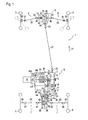
- Fig. 1 is a plain view of an entire construction of a working vehicle 1 according to the present invention.
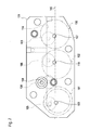
- Fig. 2 is a skeleton diagram of a power transmission structure of a rear transaxle.
- Fig. 3 is a side view of the rear transaxle.
- Fig. 4 is a cross sectional view of Fig.3 along a line A-A.
- Fig. 5 is a cross sectional view of Fig. 4 along a line B-B.
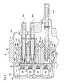
- Fig. 6 is a sectional rear view of a rear portion of the rear transaxle illustrating a shifter operation mechanism.
- Fig.7 is a cross sectional view of Fig.6 along a line C-C, illustrating a solenoid valve support block.
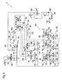
- Fig. 8 is a diagram of a hydraulic circuit of working vehicle 1.
- Fig. 9 is a block diagram of a gearshift control system of the dual clutch transmission.
- Fig. 10 is a plan view of a gearshift manipulation panel.
- Fig 11 (a) is a table indicating positions of shifters and states of first and second clutches in correspondence to every speed of the dual clutch transmission in a normal traveling mode.
- Fig 11 (b) is a table indicating positions of shifters and states of first and second clutches in correspondence to every speed of the dual clutch transmission in a reverse mode.
- Fig. 12 is a diagram showing a representative process of gearshift by the dual clutch transmission.
- Fig. 13 is a graph of characteristic lines indicating respective gearshift points in correspondence to variation of accelerator position in relation to vehicle speed.
- Fig. 14 is a partial view of a hydraulic circuit illustrating a construction of the hydraulic pump according to another embodiment.
- Fig. 15 is a plain view of an entire construction of a working vehicle 210 according to another embodiment.
- Fig. 16 is a plain view of an entire construction of a working vehicle 211 according to another embodiment.
- Fig. 17 is a plain view of an entire construction of a working vehicle 224 according to another embodiment.
- Fig. 18 is a flow diagram showing a procedure of a brake assisting control.
- Fig. 19 is a flow diagram showing a procedure of a switching point control.
- Fig. 20 is a partial block diagram of a traveling load detection unit.
- Fig. 21 is a flow diagram showing a procedure of the traveling load detection control.
- DC transmission 2 An entire structure of a working vehicle 1 equipped with a dual clutch transmission (hereinafter, referred to "DC transmission") 2 will be described with reference to Figs. 1 to 4 .
- Vehicle 1 faces forward in a direction designated by an arrow 71 in Fig. 1 , and hereinafter, positions and directions of all members will be defined on the assumption that the forward direction of working vehicle 1 is designated by arrow 71.
- Working vehicle 1 is provided at a front portion thereof with a front transaxle 5 supporting and driving a pair of right and left front axles 4 fixed to respective right and left front wheels 3.
- Working vehicle 1 is provided at a middle-and-rear portion thereof with a rear transaxle 8 supporting and driving a pair of right and left rear axles 7 fixed to respective right and left rear wheels 6.
- Working vehicle 1 is provided with an engine 9 on one of left and right sides (in this embodiment, on the left side) of rear transaxle 8.
- Rear transaxle 8 includes a transaxle casing 38, which supports an input shaft 11 and right and left rear axles 7, and incorporates DC transmission 2 and differential gear assemblies 28 and 26.
- Input shaft 11 receives power from engine 9, and DC transmission 2 transmits the power from input shaft 11 to central differential gear assembly 28 through an output gear 27.
- Central differential gear assembly 28 differentially distributes the output of DC transmission 2 between differential yoke shafts 19 and 20. The rotary force of differential yoke shaft 19 is transmitted to a rear wheel differential gear assembly 26 in rear transaxle 8 so as to differentially drive right and left rear wheels 6.
- the rotary force of differential yoke shaft 20 is transmitted to a front wheel differential gear assembly 25 in front transaxle 5 in front of rear transaxle 8 through a front wheel driving PTO section 24 provided on rear transaxle 8 so as to differentially drive right and left front wheels 3.
- Central differential gear assembly 28 comprises a hollow differential housing 30, a ring gear 29, a pinion shaft 32, bevel pinions 33 and right and left bevel differential side gears 34.
- Differential housing 30 is supported in rear transaxle 8 coaxially to differential yoke shafts 19 and 20.
- Ring gear 29 is fastened onto an outer circumference of differential housing 30 by bolts 31 and meshes with output shaft 27.
- Pinion shaft 32 is extended perpendicular to differential yoke shafts 19 and 20 in differential housing 30 rotatably integrally with differential housing 30.
- Opposite bevel pinions 33 are relatively rotatably disposed on pinion shaft 32.
- Bevel differential side gears 34 are fixed on proximal end portions of respective differential yoke shafts 19 and 20 and mesh with pinions 33.
- central differential gear assembly 28 is provided with a differential lock mechanism 35 so as to lock the differential rotation of differential yoke shafts 19 and 20.
- Differential lock mechanism 35 comprises a differential lock slider 36.
- Differential lock slider 36 is axially slidably fit onto an outer circumference of one of differential yoke shafts 19 and 20 (in this embodiment, differential yoke shaft 19).
- Ring gear 29 is formed with recesses 29a, and salients 36a are formed on a surface of differential lock slider 36 facing ring gear 29 so as to correspond to respective recesses 29a.
- differential lock slider 36 By sliding differential lock slider 36, salients 36a are engaged into respective recesses 29a so as to connect differential yoke shaft 19 integrally in a rotatable manner to differential housing 30, thereby differentially locking central differential gear assembly 28, i.e., driving right and left differential yoke shafts 19 and 20 at an equal rotary speed.
- Differential lock slider 36 is operatively connected to a differential lock operation device such as a lever (not shown) via a linkage (not shown). Therefore, central differential gear assembly 28 is differentially locked or unlocked by operation of the differential lock operation device, thereby improving working vehicle 1's performance for straight traveling and traveling in mud.
- Front-wheel driving PTO section 24 includes a PTO housing 40 convexly provided on one of the right and left sides of transaxle casing 38.
- Differential yoke shaft 20 is extended laterally outward from transaxle casing 38, and is connected to a transmission shaft 39 via a coupling 37.
- Transmission shaft 39 projects into PTO housing 40, and is fixedly provided thereon with a bevel gear 41 in PTO housing 40.
- PTO housing 40 journals a fore-and-aft extended PTO shaft 21 projecting forward therefrom.
- PTO shaft 21 is fixedly provided thereon with a bevel gear 42 meshing with bevel gear 41.
- PTO shaft 21 is connected to an input shaft 44 of front transaxle 5 through a universal joint 22, a propeller shaft 23, and a universal joint 43, thereby transmitting the power from engine 9 to right and left front wheels 3.
- a bevel gear 45 fixed on input shaft 44 meshes with a ring gear 46 of front wheel differential gear assembly 25.
- ring gear 46 is rotatably integrally provided on a differential casing 47, and right and left differential yoke shafts 48 and 49 are fitted into differential casing 47.
- Each of the differential yoke shafts 48 and 49 is drivingly connected at a distal end thereof to each of front wheel axles 50 serving as central axes of respective steerable front wheels 3 via a universal joint 53, a half shaft 52 and a universal joint 51.
- Front wheel differential gear assembly 25 is provided with a differential lock mechanism 74, similar to central differential gear assembly 28 with differential lock mechanism 35.
- a ring gear 55 is rotatably integrally provided on a differential casing 56 and meshes with an output gear 54 formed on a distal end of differential yoke shaft 19.
- a pinion shaft 58 pivoting a pair of opposite differential pinions 57 is rotatably integrally provided in differential casing 56.
- Right and left differential side gears 59 are fixed on proximal ends of respective differential yoke shafts 60 and 61 and mesh with differential pinions 57.
- Each of differential yoke shafts 60 and 61 is drivingly connected at a distal end thereof to each of rear wheel axles 65 serving as central axes of respective rear wheels 6 via a universal joint 62, a half shaft 63 and a universal joint 64.
- Rear wheel differential gear assembly 26 is provided with differential lock mechanism 66, similar to front wheel differential gear assembly 25 with differential lock mechanism 74.
- Transaxle casing 38 of rear transaxle 8, which incorporates DC transmission 2 includes a left casing 68, a central casing 69, a right casing 70.
- a seal casing 67 is attached to a vertical outside (left) surface of an upper portion of left casing 68.
- Front wheel driving PTO housing 40 is attached to a vertical outside (right) surface of a substantially vertically middle portion of right casing 70.
- Input shaft 11, a second clutch output shaft 13 extended coaxially to input shaft 11, an intermediate shaft 18, a speed change shaft 15, a transmission output shaft 17, coaxial differential yoke shafts 19 and 20, and coaxial differential yoke shafts 60, 61 are extended in transaxle casing 38 in the laterally horizontal direction of vehicle 1 and in parallel to one another.
- a dual clutch unit 82 including a first clutch C1 and a second clutch C2, is provided around input shaft 11 in transaxle casing 38.
- Dual clutch unit 82 includes a clutch housing 82a shared between first and second clutches C1 and C2.
- Clutch housing 82a is fixed at a central boss portion thereof on input shaft 11 between first clutch output shaft 12 and cup-shaped portion 13a.
- Clutch housing 82a is formed integrally with a partition portion 82b, a left drum-shaped portion and a right drum-shaped portion as well as the central boss portion. Partition portion 82b is extended radially outward from the central boss portion.
- the left drum-shaped portion is extended leftward from the outer peripheral end of partition portion 82b and is disposed around a right portion of first clutch output shaft 12.
- the right drum-shaped portion is extended rightward from the outer peripheral end of partition portion 82b and is disposed around cup-shaped portion 13a of second clutch output shaft 13.
- friction elements which are relatively unrotatably and axially slidably fit to the right portion of first clutch output shaft 12 and the left drum-shaped portion of clutch housing 82a, are alternately aligned in the axial direction of input shaft 11, so as to constitute first clutch C1 interposed between input shaft 11 and first clutch output shaft 12.
- first and second clutches C1 and C2 are hydraulically activated clutches.
- a first piston 86 is disposed axially slidably along the central boss portion and left drum-shaped portion of clutch housing 82a, and is biased toward partition portion 82b by a spring 85.
- oil is supplied into a cylinder chamber 83 between partition portion 82b and first piston 86, the oil pushes first piston 86 leftward against spring 85 so as to press the friction elements against one another, thereby engaging first clutch C1.
- a second piston 87 is disposed axially slidably along the central boss portion and right drum-shaped portion of clutch housing 82, and is biased toward partition portion 82b by a spring 85.
- fluid passages 88, 89 and 90 are formed in input shaft 11, and are opened at one end thereof on the outer circumference surface of the outer (left) end portion of input shaft 11.
- Fluid passage 88 communicates at the one end thereof with a solenoid proportional reducing valve 91 for controlling the hydraulic pressure of the hydraulic oil to first clutch part C1.
- Fluid passage 89 communicates at the one end thereof with a solenoid proportional reducing valve 92 for controlling the hydraulic pressure of the hydraulic oil to second clutch C2.
- Fluid passage 90 communicates at the one end thereof with a changeover valve 93 for controlling the supply and discharge of lubricant oil to and from second clutch C2.
- Fluid passage 88 communicates at the other end thereof with cylinder chamber 83 between partition portion 82b and first piston 86.
- Fluid passage 89 communicates with cylinder chamber 84 between partition portion 82b and second piston 87.
- Fluid passage 90 is bifurcated at the other end thereof to communicate with gaps between the inner circumference surfaces of respective pistons 86 and 87 and the outer circumference surface of input shaft 11, thereby supplying lubricant oil for the slide of pistons 86 and 87.
- An electronic control system for gearshifting DC transmission 2 is configured as shown in Fig. 9 .
- Working vehicle 1 is provided with a speed change operation lever 95 serving as a manipulator for operating DC transmission 2.
- a lever position sensor 113 is provided to detect an operation position of speed change operating lever 95.
- a position detection signal corresponding to the position of lever 95 is transmitted from sensor 113 to a controller 94.
- an accelerator sensor 120 for detecting the depression of an accelerator pedal (not shown) and a vehicle speed sensor 121 for detecting the actual traveling speed of working vehicle 1 transmit respective detection signals to controller 94. According to the signals from these sensors, controller 94 commands to excite/non-excite solenoids of valves 91 and 92 for first and second clutches C1 and C2.
- a diametrically small gear 72 is formed on the outer circumference of first clutch output shaft 12.
- Gear 72 meshes with a diametrically large gear 96 fixed on speed change shaft 15.
- a deceleration gear 16, a reversing gear 78 and a gear 77 are relatively rotatably fitted onto speed change shaft 15.
- a deceleration gear 14 is relatively rotatably provided on second clutch output shaft 13.
- a gear 73 is fixed on deceleration gear 14.
- Output gear 27 and a diametrically large gear 81 are fixed on transmission output shaft 17.
- Both of deceleration gears 14 and 16 are double gears each integrally consisting of diametrically large and small gears.
- Deceleration gear 14 comprises a diametrically large gear 14a and a diametrically small gear 14b.
- Deceleration gear 16 comprises a diametrically large gear 16a and a diametrically small gear 16b.
- diametrically small gear 72 and a diametrically large gear 96 mesh with each other so as to constitute a first deceleration gear train.
- Diametrically small gear 14b of deceleration gear 14 and diametrically large gear 16a of deceleration gear 16 mesh with each other so as to constitute a second deceleration gear train.
- Diametrically small gear 16b of deceleration gear 16 and diametrically large gear 81 mesh with each other so as to constitute a third deceleration gear train.
- backward-driving gear 78 meshes with an idle gear 75 on intermediate shaft 18.
- Idle gear 75 meshes with diametrically large gear 14a of deceleration gear 14.
- Reversing gear 78, idle gear 75 and diametrically large gear 14a constitute a reversing gear train.
- Gears 77 and 73 mesh with each other so as to constitute an adjusting gear train.
- a third spline hub 99 is relatively unrotatably engaged onto the speed change shaft 15 on one side (the left side in this embodiment) of deceleration gear 16 via a synchronization mechanism 99b such as a synchromesh.
- a second spline hub 98 is relatively unrotatably engaged on speed change shaft 15 via a synchronization mechanism 98b between reversing gear 78 and gear 77.
- a first spline hub 97 is relatively unrotatably engaged onto second clutch output shaft 13 via a synchronization mechanism 97b on one side (the left side in this embodiment) of deceleration gear 14.
- a first shifter 97a is axially slidably and relatively unrotatably engaged onto first spline hub 97.
- a second shifter 98a is axially slidably and relatively unrotatably engaged onto second spline hub 98.
- a third shifter 99a is axially slidably and relatively unrotatably engaged onto third spline hub 99.
- a clutch-teethed portion 14c is formed on an end of deceleration gear 14 facing first spline hub 97.
- a clutch-teethed portion 16c is formed on an end of deceleration gear 16 facing third spline hub 99.
- Clutch-teethed portions 77a and 78a are formed on respective ends of gears 77 and 78 facing second spline hub 98 therebetween.
- a shifter operation mechanism 143 is provided in transaxle casing 38 so as to control shifts of these shifters 97a, 98a and 99a among predetermined positions.
- Shifter operation mechanism 143 includes first, second and third hydraulic cylinders 100, 101 and 102 serving as hydraulic actuators for sliding shifters 97a, 98a and 99a.
- a fork 125 fitted on first shifter 97a (see Figs. 4 and 5 ) is fixed at a boss 128 thereof on a piston rod 100a of first cylinder 101.
- Central casing 69 is formed with a cylinder block portion 142 in which hydraulic cylinders 100, 101 and 102 are formed so as to extend laterally in parallel to one another.
- a valve support block 131 is fixed at a right side surface 131 a thereof to a left end surface of cylinder block portion 142 so as to define the left ends of hydraulic cylinders 100, 101 and 102.
- a solenoid changeover valve 103 is provided for first cylinder 100 and first shifter 97a.
- Solenoid changeover valves 104 and 105 are provided for second cylinder 101 and second shifter 98a.
- Solenoid changeover valve 106 is provided for third cylinder 102 and third shifter 99a.
- Solenoid changeover valves 103, 104, 105 and 106 are fixedly fitted rightward into valve support block 131 laterally opposite to cylinder block portion 142 as shown in Fig. 6 , and are electrically connected to controller 94 in the electronic control system for DC transmission 2 as shown in Fig. 9 .
- First hydraulic cylinder 100 includes a cylinder chamber 100d which is formed in cylinder block portion 142 and is closed at a left aperture thereof by right side surface 131 a of valve support block 131.
- a fluid chamber 100b is formed in cylinder chamber 100d between right side surface 131 a and a left end of a piston 100c fixed on one (left) end portion of piston rod 100a.
- Fluid chamber 100b is connected to solenoid changeover valve 103 via a fluid passage 107 formed in valve support block 131.
- a return spring 132 is wound around piston rod 100a between a right side of piston 100c and a right inner wall of cylinder chamber 100d so as to bias piston 100c toward fluid chamber 100b.
- a stopper 134 is fixed to an inner peripheral surface of cylinder chamber 100d so as to define a left limit position of piston 100c for preventing piston 100c from sliding further leftward therefrom.
- third hydraulic cylinder 102 includes a cylinder chamber 102d which is formed in cylinder block portion 142 and is closed at a left aperture thereof by right side surface 131a of valve support block 131.
- a fluid chamber 102b is formed in cylinder chamber 102d between right side surface 131 a and a piston 102c provided on one (left) end of piston rod 102a.
- Fluid chamber 102b is connected to solenoid changeover valve 106 via a fluid passage 110 formed in valve support block 131.
- a return spring 133 is wound around piston rod 102a between a right side of the piston 102c and a right inner wall of cylinder chamber 102d so as to bias piston 102c toward fluid chamber 102b.
- a stopper 135 is fixed to an inner peripheral surface of cylinder chamber 102d so as to define a left limit position of piston 102c for preventing piston 102c from sliding further leftward therefrom.
- solenoid change over valve 103 or 106 opens corresponding fluid chamber 100b or 102b to a fluid sump 136 through a common fluid passage 115, thereby preventing corresponding piston 100c or 102c from receiving waste pressure, and thereby accurately retaining piston 100c or 102c.
- valve 103 or 106 supplies clutch-operation fluid into corresponding fluid chamber 100b or 102b through a common fluid passage 114 formed in valve support block 131. Due to the fluid supply into fluid chamber 100b against spring 132, piston 100c reaches a position A so that shifter 97a meshes with clutch-teethed portion 14c (see Figs. 2 and 8 ). Due to the fluid supply into fluid chamber 102b against spring 133, piston 102c reaches a position D so that shifter 99a meshes with clutch-teethed portion 16c (see Figs. 2 and 8 ).
- Piston rods 100a and 102a project outward from the cylinder block portion so as to be supported at right end portions thereof by a wall of right casing 70.
- Bosses 128 and 130 of forks 125 and 127 are fixed on respective piston rods 100a and 102a between cylinder block portion 142 and the wall of right casing 70.
- annular gaps 137 and 138 are provided between respective piston rods 100a and 102a and the wall of cylinder block portion 142 so that fluid compressed by rightward sliding of each of pistons 100c and 102c can be quickly released from each cylinder 100 or 102 through corresponding gap 137 or 138 to fluid sump 136 in transaxle casing 38.
- each of hydraulic cylinders 100 and 102 is a single-action cylinder in which corresponding fluid chamber 100b or 102b is disposed on only one side of its piston 100c or 102c, and corresponding return spring 132 or 133 on the other opposite side of its piston 100c or 102c.
- This arrangement thereby reduces costs for accurately forming fluid chambers and costs for connecting pipes and valves to fluid passages for supplying fluid to the respective fluid chambers, because the number of fluid chambers and the number of fluid passages for supplying the fluid chambers of these cylinders are reduced in comparison with a double-action cylinder including opposite fluid chambers on both sides of its piston.
- a cylinder chamber 101d of second hydraulic cylinder 101 is formed in cylinder block portion 142 and is closed at the left aperture thereof by right side surface 131 a of valve support block 131, similar to cylinder chambers 100d and 102d of cylinders 100 and 102.
- a main piston 140 including a diametrically large portion 140a and a diametrically small portion 140b is fixed on one end of piston rod 101 a.
- a cylindrical sub piston 141 is axially slidably fitted on diametrically small portion 140b of main piston 140 and has a diameter larger than that of diametrically large portion 140a of main piston 140.
- Main piston 140a and sub piston 141 constitute a piston 139.
- Second cylinder 101 is a double-action cylinder including a left fluid chamber 101 b and a right fluid chamber 101c disposed on opposite sides of piston 139. Solenoid change over valves 104 and 105 are connected to respective fluid chambers 101 b and 101 c.
- valve 105 Drains fluid from fluid chamber 101c and piston 139 receives the hydraulic pressure of fluid in fluid chamber 101 b supplied by valve 104 so that both main piston 140 and sub piston 141 slide leftward and abut against a distal end of fluid chamber 101 c defined as position C, thereby engaging second sifter 98a with clutch-teethed portion 78a.
- valve support block 131 supporting solenoid change over valves 103, 104, 105 and 106 also serves as a part of each of cylinders 100, 101 and 102, thereby reducing the number of parts and costs. Further, valve support block 131 can be removed from cylinder block portion 142 so as to easily open cylinder chambers 100d, 101d and 102d, thereby facilitating maintenance.
- a speed change operation panel 111 as shown in Fig. 10 is provided adjacent to an operator's seat (not shown) on working vehicle 1.
- a guide slot 112 is formed in panel 111 so as to guide lateral and longitudinal rotations of speed change operation lever 95 serving as a manipulator for gearshift of DC transmission 2.
- Guide slot 112 includes three parallel longitudinal slots 116, 117 and 118 extended in the fore-and-aft direction (they appear vertical in Fig. 10 ), and includes a pair of coaxial lateral slots 119.
- One lateral slot 119 is interposed between longitudinal slots 116 and 117, and the other lateral slot 119 is interposed between longitudinal slots 117 and 118.
- Lever position sensor 113 detects the position of speed change operation lever 95 moving along guide slot 112 and transmits a position detection signal to controller 94. Accordingly, controller 94 issues the above-mentioned gearshift command signal to valves 91, 92, 103, 104, 105 and 106. Further, controller 94 issues a brake command signal to a parking brake (not shown).
- Speed change operation lever 95 is normally rotated fore and aft in longitudinal slot 117.
- DC transmission 2 is automatically gearshifted to change the forward traveling speed so as to correspond to the accelerator position (e.g., the depression of an accelerator pedal or the opening degree of an engine throttle) and the vehicle speed (i.e., the actual traveling speed of working vehicle 1), and this setting is referred to as an automatic gearshift mode.
- DC transmission 2 can be optionally gearshifted to change the forward traveling speed, and this setting is referred to as a manual gearshift mode, which belongs to the normal traveling mode.
- a reverse mode is established.
- DC transmission 2 can be gearshifted between the predetermined forward-traveling speed and the forward-traveling speed.
- the reverse mode is convenient for works requiring frequent switching of the forward/backward traveling direction, such as scraping and carrying earth and sand by a front loader of working vehicle 1.
- the movement of speed change operation lever 95 among longitudinal slots 116, 117 and 118 depends on the lateral rotation of lever 95 along lateral slot 119.
- a power train structure in the normal traveling mode will be described with reference to Figs. 2 , 10 , 11(a) , 12 and 13 .
- speed change operation lever 95 is disposed in position 117D so as to establish the automatic gearshift mode, the forward traveling speed is automatically determined and changed so as to correspond to the relation of the accelerator position (such as the depression of an accelerator pedal (not shown) or the opening degree of the throttle of engine 9) to the vehicle speed (i.e., the actual traveling speed of working vehicle 1).
- shifter control mechanism 143 is controlled so that first shifter 97a is placed at position A so as to rotatably integrally engage deceleration gear 14 with second clutch output shaft 13.
- Second shifter 98a is placed at position B so as to rotatably integrally engage gear 77 with speed change shaft 15.
- Third shifter 99a is placed at position N so as to relatively rotatably disengage from speed change shaft 15.
- gears 72 and 56 serve as the first deceleration gear train
- gears 77 and 73 serve as the adjusting gear train
- gears 14b and 16a serve as the second deceleration gear train
- gears 16b and 81 serve as the third deceleration gear train.
- the forward-traveling first speed drive train is defined as the series connection of first clutch output shaft 12, the first deceleration gear train, speed change shaft 15, the adjusting gear train, second clutch output shaft 13, the second deceleration gear train and the third deceleration gear train.
- the forward-traveling second speed drive train is defined as the series connection of second clutch output shaft 13, the second deceleration gear train and the third deceleration gear train.
- This state is referred to as a forward-traveling low speed shifter state.
- first clutch C1 When first clutch C1 is engaged and second clutch C2 is disengaged in the forward-traveling low speed shifter state, the forward-traveling first speed drive train is activated and the forward-traveling second speed drive train is idled.
- first clutch C1 is disengaged and second clutch C2 is engaged in the forward-traveling low speed shifter state, the forward-traveling second speed drive train is activated and the forward-traveling first speed drive train is idled.
- set speed change operation lever 95 is set to automatic forward-traveling speed change position 117D and by slightly depressing the accelerator pedal. Shifters 97a, 98a and 99a are then set into the forward-traveling low speed shifter state, and then, only first clutch C1 is engaged.
- the forward-traveling low speed shifter state is kept, first clutch C1 having been engaged is disengaged, and second clutch C2 having been disengaged is engaged. Accordingly, the forward-traveling second speed drive train is activated so that the rotary force of input shaft 11 is transmitted to transmission output shaft 17 through engaged second clutch C2 and the forward-traveling second speed drive train so as to be outputted as the forward-traveling second speed output of DC transmission 2 to front and rear axles 4 and 7.
- shifter control mechanism 143 To shift up DC transmission 2 from the forward-traveling second speed to the forward-traveling third speed, shifter control mechanism 143 is controlled to move second shifter 98a from position B to position N, to move third shifter 99a from position N to position D, and to hold first shifter 97a at position A while keeping the disengagement of first clutch C1 and the engagement of second clutch C2. Due to the disengagement of first clutch C1, speed change shaft 15 constantly drivingly connected to first clutch output shaft 12 is idled so as to prevent the movement of first and second shifters 98a and 99a from suddenly changing the output rotary speed of DC transmission 2.
- first shifter 97a is set at position A
- second shifter 98a is set at position N
- third shifter 99a is set at position D
- the forward-traveling middle speed shifter state both the above-mentioned forward-traveling second speed drive train and a forward-traveling third speed drive train are simultaneously selected to be activated.
- the forward-traveling third speed drive train is defined as the series connection of first clutch output shaft 12, the first deceleration gear train, speed change shaft 15 and the third deceleration gear train.
- shifter control mechanism 143 is controlled to move first shifter 97a from position A to position N, second shifter 98a is controlled to move from position N to position B, and third shifter 99a is held at position D. Due to the disengagement of second clutch C2, second clutch output shaft 13 is idled so that the movement of first shifter 97a on second clutch output shaft 13 does not influence variation of the output rotary speed of DC transmission 2. Second shifter 98a moved to position B is moderated in engaging to gear 77 by synchromesh 98b.
- each of the shift up and shift down processes of DC transmission 2 in the automatic gearshift mode is performed by shifting engagement between first and second clutches C1 and C2 so as to alternately engage/disengage clutches C1 and C2.
- first and second clutches C1 and C2 so as to alternately engage/disengage clutches C1 and C2.
- clutches C1 and C2 having been disengaged one of clutches C1 and C2 having been disengaged is engaged, and meanwhile, the other of clutches C1 and C2 having been engaged is disengaged.
- This process for exchanging engagement/disengagement between clutches C1 and C2 is simply referred to as "clutch switching".
- the forward traveling high speed shifter state is changed to the forward traveling middle speed shifter state before the clutch switching, i.e., before engaged first clutch C1 is disengaged and disengaged second clutch C2 is engaged.
- the forward traveling middle speed shifter state is changed to the forward traveling low speed shifter state before the clutch switching, i.e., before disengaged first clutch C1 is engaged and engaged second clutch C2 is disengaged.
- All the shift up and shift down processes are performed only by the clutch switching without change of the shifter state. For example, when the forward traveling second speed having been established by shift up from the forward traveling first speed is shifted down to the forward traveling first speed, disengaged first clutch C1 is engaged and engaged second clutch C2 is disengaged while keeping the forward traveling low speed shifter state.
- controller 94 issues a gearshift command signal at a timing X. Firstly, immediately after timing X, second shifter 98a is moved from position B to position N and third shifter 99a is moved from position N to position D, so as to change the forward traveling low speed shifter state to the forward traveling middle shifter state. At a timing Y after the completion of the change to the forward traveling middle speed shifter state, the engagement action of disengaged first clutch C1 and the disengagement action of engaged second clutch C2 are started.
- the clutch pressure of first clutch C1 is gradually increased so that the engagement action of first clutch C1 is gradually progressed from the disengagement state to the engagement state, and meanwhile, the clutch pressure of second clutch C2 is gradually decreased so that the disengagement action of second clutch C2 is gradually progressed from the engagement state to the disengagement state.
- the clutch pressure of first clutch C1 becomes the maximum value so as to complete the engagement action of first clutch C1
- the clutch pressure of second clutch C2 becomes the minimum value so as to complete the disengagement action of second clutch C2, that is, the gearshift is completed so that the forward traveling third speed is established.
- the above-mentioned clutch pressure control for gradually increasing/decreasing the clutch pressures of first and second clutches C1 and C2 for preset clutch switching time 205 with the passage through equal pressure point 201 is referred to as "cross wave control".
- the cross wave control is performed at every shift up or shift down process of DC transmission 2 during setting of the automatic gearshift mode, i.e., while speed change operation lever 95 is set at automatic forward traveling speed change position 117D.
- each of the shift up and shift down processes is performed by only the clutch switching without movement of the shifter or shifters. Consequently, these shifts up and shifts down are accelerated.
- the later-discussed forward/backward traveling direction switching in the reverse mode is an adaptation of this gearshift pattern between neighboring one forward traveling odd-numbered speed and one forward traveling even-numbered speed.
- the vehicle speed corresponding to the accelerator position for issuing the gearshift command signal for shift down from the other speed to the one speed is less than that for issuing the gearshift command signal for shift up from the one speed to the other speed, thereby achieving a hysteresis gearshift control for avoiding excessively sensitive repeat of shift up and shift down.
- gearshift point characteristic line 122 for shift up from the forward traveling first speed to the forward traveling second speed and a gearshift point characteristic line 124 for shift up from the forward traveling third speed to the forward traveling fourth speed due to the settings of deceleration ratios, the vehicle speed range corresponding to the accelerator position for issuing the gearshift command signal for gearshift between low speeds is narrower than that for issuing the gearshift command signal for gearshift between high speeds.
- the forward traveling first speed drive train includes the first deceleration gear train (gears 72 and 96), the adjusting gear train (gears 77 and 73), the second deceleration gear train (gears 14b and 16a), and the third deceleration gear train (gears 16b and 81).
- the forward traveling forth speed drive train includes the adjusting gear train (gears 77 and 73) and the third deceleration gear train (gears 16b and 81).
- the forward traveling fourth speed is frequently used, and the frequency of using the forward-traveling first speed is not high.
- the adjusting gear train is shared between the forward traveling first speed drive train and the forward traveling fourth speed drive train, thereby reducing the number of components, simplifying the transmission structure, minimizing the space for arranging gears, enhancing the flexibility in layout of components in DC transmission 2, and thereby minimizing and economizing working vehicle 1.
- speed change operation lever 95 is set at a backward traveling position 117R. Accordingly, controller 94 issues a gearshift command signal to set second shifter 98a to position C for rotatably integrally engaging reversing gear 78 with speed change shaft 15, and to set third shifter 99a to position N for relatively rotatably disengaging deceleration gear 16 from speed change shaft 15. Since second clutch C2 is disengaged during the backward traveling, first shifter 97a may be disposed at either position A for rotatably integrally engaging deceleration gear 14 with second clutch output shaft 13 or position N for relatively rotatably disengaging deceleration gear 14 from second clutch output shaft 13.
- This state where second shifter 98a is set at position C and third shifter 99a is set at position N regardless of the position of first shifter 97a, is referred to as a backward traveling shifter state.
- a backward traveling speed drive train is selected to be activated.
- the backward traveling speed drive train is defined as the series connection of first clutch output shaft 12; the first deceleration gear train; speed change shaft 15; the reversing gear train including gears 78, 75 and 14a; the second deceleration gear train; and the third deceleration gear train.
- first clutch C1 is engaged and second clutch C2 is disengaged
- the backward traveling speed drive train is activated.
- the rotary force of input shaft 11 is transmitted to transmission output shaft 11 through engaged first clutch C1 and the backward traveling speed drive train, so as to be outputted as a backward traveling output of DC transmission 2 to front and rear axles 4 and 7.
- the manual forward traveling gearshift mode in the normal traveling mode will be described with reference to Figs. 10 , 11(a ) and 12 .
- the manual forward traveling gearshift mode where an operator can optionally set any forward traveling speed is established by arranging speed change operation lever 95 into longitudinal slot 116. Every time speed change operation lever 95 is pressed against one (a front) end edge of longitudinal slot 116 defined as a shift up position 116U, controller 94 transmits a gearshift command signal for shift up by one speed to valves 91, 92, 103, 104, 105 and 106 so as to shift up the forward traveling speed from the first speed to the fourth speed one by one.
- the reverse mode is defined as a mode where the switching between the predetermined forward traveling speed and the backward traveling speed is rapidly performed due to the switching of speed change operation lever 95 along longitudinal slot 118, between a forward traveling position 118F and a backward traveling position 118R.
- shifters 97a, 98a and 99a are set and held at respective positions A, C and N as shown in Fig. 11 (b) .
- the backward traveling shifter state setting shifter 97a at position A is selected for the reverse mode.
- This shifter state is referred to as a reverse mode shifter state.
- the backward traveling speed drive train is selected to be activated as mentioned above, and simultaneously, the forward traveling second speed drive train is selected to be activated. Therefore, in the reverse mode shifter state, when first clutch C1 is engaged and second clutch C2 is disengaged, the backward traveling speed drive train is activated and the forward traveling second speed drive train is idled. On the other hand, in the reverse mode shifter state, when first clutch C1 is disengaged and second clutch C2 is engaged, the forward traveling second speed drive train is activated and the backward traveling speed drive train is idled.
- the control system is configured so that the setting of speed control operation lever 95 to forward traveling position 118F causes the engagement of first clutch C1 and disengagement of second clutch C2, and the setting of speed control operation lever 95 to backward traveling position 118R causes the disengagement of first clutch C1 and engagement of second clutch C2. Therefore, the switching of DC transmission 2 between the forward traveling second speed and the backward traveling speed is swiftly performed by only the alternate engagement/disengagement switching between first and second clutches C1 and C2 while keeping the shifter state, i.e., without movement of shifters 97a, 98a and 99a. In this way, during setting of the reverse mode, the time from the issuance of gearshift command signal from controller 94 till the completion of gearshift is short because, referring to Fig.
- DC transmission 2 shown in Figs. 2 , 4 and others is configured so that the backward traveling speed drive train is activated by engaging first clutch C1, thereby enabling setting of the reverse mode shifter state where the backward traveling speed drive train is selected to be activated simultaneously with the forward traveling second speed drive train which is activated by engaging second clutch C2.
- the predetermined one forward traveling speed set by the reverse mode should be one forward traveling odd-numbered speed, e.g., a forward traveling first speed as the lowest forward-traveling odd-numbered speed.
- first and second clutches C1 and C2 for gearshift of forward traveling speed is utilized for switching the forward/backward traveling direction. Therefore, no additional clutch is provided for the forward/backward traveling direction, thereby reducing the number of components and costs and improving maintenancability.
- FIG. 5 A hydraulic circuit structure of working vehicle 1 will now be described with reference to Figs. 2 to 8 and 14 , mainly describing the lubricating fluid circulation in transaxle casing 38 incorporating DC transmission 2.
- a seal casing 67 incorporating a trochoidal gear pump type hydraulic pump 145 is fixed onto an outer (left) side surface of an upper portion of left casing 68 of transaxle casing 38.
- a first transmission chamber 177 is formed between left casing 68 and a support wall 69a formed of central casing 69.
- a pump shaft 145a of hydraulic pump 145 is journalled by a wall portion 68b of left casing 68 through bearings, and is extended at an end thereof outward from wall portion 68b into first transmission chamber 177 so as to be fixedly provided thereon with a pump gear 146.
- Pump gear 146 meshes with a gear 147 fixed on an intermediate portion of input shaft 11, so that hydraulic pump 145 is driven by input shaft 11 receiving power from engine 9.
- the diameter of gear 147 is smaller than that of pump gear 146, and the number of teeth of gear 147 is less than that of pump gear 146, so that the rotary speed of pump shaft 145a becomes slower than that of input shaft 11. Therefore, a normal slow-rotation type hydraulic pump which is lower-priced than a special fast-rotation type hydraulic pump can be adopted as hydraulic pump 145, thereby economizing transaxle 8.
- an inlet port of hydraulic pump 145 is opened through a fluid passage 149 and a filter 148 to a fluid sump 136 provided in first transmission chamber 177 or in another portion in transaxle casing 38 so that hydraulic pump 145 is supplied with fluid from fluid sump 136.
- An outlet port of hydraulic pump 145 is opened to a fluid passage 150.
- a distribution unit 151 bifurcates fluid passage 150 into a fluid passage 152 for an external working device and a fluid passage 153 for a power steering system and the gearshift of DC transmission 2.
- fluid passages 152 and 153 are provided with respective throttles (e.g., orifices) 151 a and 151 b for regulating pressure.
- Fluid passage 152 is connected to a changeover valve 154, and changeover valve 154 is connected to a hydraulic lifting cylinder 156 through a piping 155. Due to control of changeover valve 154 supplied with fluid from hydraulic pump 145, a hydraulic lifting cylinder 156 is controlled so as to control vertical rotation of lifting arms 157 for lifting the external working device.
- a power steering hydraulic valve device 158 is fluidly connected to an intermediate portion of fluid passage 153 so as to extract fluid for supplying a power steering cylinder 159 from fluid passage 153. In this way, power steering hydraulic valve device 158 is supplied with fluid from hydraulic pump 145, and is controlled by manipulating a steering operation device, such as a steering wheel, so as to control power steering cylinder 159 for turning front wheels 3.
- hydraulic pump 145 attached on transaxle casing 38 serves as a single hydraulic pressure source which can supply pressurized fluid to not only DC transmission 2 but also the external working device, the power steering system or the like, thereby reducing the number and cost of hydraulic pumps needed for the supply of pressurized fluid to the respective hydraulic devices, simplifying the fluid passage structure, minimizing rear transaxle 8, enhancing the flexibility of layout of components in vehicle 1, and minimizing and economizing vehicle 1.
- Fluid passage 161 is passed through a check valve 168 and a filter 169 and is further bifurcated into two passages connected to respective pump ports of respective solenoid proportional deceleration valves 91 and 92. Outlet ports of solenoid proportional deceleration valves 91 and 92 are connected to respective fluid passages 88 and 89.
- hydraulic pump 145 is adapted to supply pressurized fluid as clutch pressure fluid to cylinder chamber 83 of first clutch C1 and cylinder chamber 84 of second clutch C2.
- Fluid passage 162 is passed through a pressure regulation valve 170 and is bifurcated between fluid passages 163 and 164. Fluid passage 163 is connected to changeover valve 93 controlling the supply and discharge of lubricant oil to and from first and second clutches C1 and C2. Pilot fluid passages 93a and 93b of changeover valve 93 are fluidly connected to fluid passages 88 and 89, respectively.
- pressurized fluid flows through either fluid passage 88 or 89 during the operation of first or second clutch C1 or C2
- this fluid flow supplies pilot pressure fluid to either pilot fluid passage 93a or 93b so that changeover valve 93 is shifted to connect its pump port and outlet port to each other.
- the pressurized fluid in fluid passage 163, regulated in pressure by pressure regulation valve 171 is supplied as lubricant fluid from changeover valve 93 to first and second clutches C1 and C2 through fluid passage 90.
- a fluid passage 172 is bored in seal casing 67 in parallel to input shaft 11, and fluid passage 164 is connected to fluid passage 172.
- fluid passage 173 is branched off from an intermediate portion of fluid passage 172, a bearing unit 179 including a bearing 180, and a fluid seal 181 is configured so as to support a left end of input shaft 11.
- fluid passage 173 is opened to bearing unit 179, so that hydraulic pump 145 forcibly supplies pressurized fluid as lubricant fluid to bearing unit 179.
- seal casing 67 integrally incorporates lubricant fluid passage 173 and bearing unit 179 for supporting input shaft 11, and is further formed integrally with a pump casing portion 67a into which hydraulic pump 145 is assembled. Therefore, lubricant fluid passage 173, bearing unit 179 and pump casing portion 67a are collected in seal casing 67 so as to require no additional relevant piping, bearing, or pump casing, thereby reducing the number of components and costs, and minimizing transaxle casing 38.
- left casing 68 is formed integrally with an outer wall portion 68b penetrated by a fluid passage 68c, and is formed integrally with a bearing wall portion 182 supporting a left end of speed change shaft 15 through a bearing.
- a fluid chamber 175 is provided between outer wall portion 68b and bearing wall portion 182.
- Fluid passage 172 is opened to fluid chamber 175 through fluid passage 68c.
- a vertical fluid passage 176 is bored in outer wall portion 68b and is opened at a bottom end thereof to fluid chamber 175.
- Fluid passage 176 is formed at an upper portion thereof with a delivery port 176a opened to dual clutch unit 82 in first transmission chamber 177. In this way, the pressurized fluid from hydraulic pump 145 is forcibly sprayed out as lubricant fluid from delivery port 176a to dual clutch unit 82 through fluid passages 172 and 68c, fluid chamber 175 and fluid passage 176.
- Speed change shaft 15 is penetrated on the central axis thereof by an axial fluid passage 174.
- Axial fluid passage 174 is opened at a left end thereof to fluid chamber 175.
- Right casing 70 is formed integrally with an outer wall portion 70a. Further, right casing 70 is formed integrally with a bearing wall portion 183 journaling a right end of speed change shaft 15 through a bearing 187, and is formed integrally with a bearing wall portion 185 journaling a right end of second clutch output shaft 13 through a bearing 186.
- a bearing cover 188 is bridged between bearings 186 and 187.
- a vertical groove 70b is formed on an inside surface of outer wall portion 70a and is covered with bearing cover 188 so as to form a fluid passage 184.
- radial fluid holes 174a, 174b and 174c are extended in speed change shaft 15 from axially intermediate portions of axial fluid passage 174, and are opened on the outer peripheral surface of speed change shaft 15 to inner peripheral surfaces of respective gears 16, 78 and 77 on speed change shaft 15.
- DC transmission 2 is provided with a lubricant fluid circuit 190, which is formed in transaxle casing 38, which includes fluid chamber 175 and fluid passage 176 formed in left casing 68, fluid passage 184 formed in right casing 70, axial fluid passage 174 and radial fluid holes 174a, 174b and 174c formed in speed change shaft 15, and axial fluid passage 189 and radial fluid hole 189a formed in second clutch output shaft 13.
- Lubricant fluid circuit 190 surely delivers the pressurized fluid from hydraulic pump 145 as lubricant fluid to the components of DC transmission 2, e.g., dual clutch unit 82, the speed gear trains, the synchromeshes and the bearings.
- the lubricant fluid delivered by hydraulic pump 145 through lubricant fluid passage 190 is sprayed and dropped so as to lubricate the members of DC transmission 2 such as dual clutch unit 82, the speed gears and synchromeshes, and then is recovered into fluid sump 136.
- the members of DC transmission 2 such as dual clutch unit 82, the speed gears and synchromeshes, and then is recovered into fluid sump 136.
- fluid sump 136 has a fluid surface level 191 which is lower than transmission output shaft 17 so as to prevent the components of DC transmission 2, e.g., dual clutch unit 82, speed change shaft 15, second clutch output shaft 13, the speed gears and synchromeshes 97b, 98b and 99b, from being submerged in fluid sump 136, thereby avoiding excessive agitation of the fluid of fluid sump 136 causing the temperature rise of fluid.
- This is very advantageous for reducing the fluid agitation resistance causing the reduction of power transmission efficiency and the temperature rise of fluid, in consideration that dual clutch unit 82 and synchromeshes 97b, 98b and 99b cause great fluid agitation resistance.
- controller 94 commands vehicle inclination angle sensor 193 to detect the vehicle inclination angle, and receives the vehicle inclination angle signal from vehicle inclination angle sensor 192. Accordingly, controller 94 decides whether the road on which working vehicle 1 stays is upwardly sloped or not (Step S1). When controller 94 decides that working vehicle 1 is not upwardly sloped (Step S1, NO), controller 94 transmits a brake command signal for releasing the braking force to solenoid changeover valve 194. Accordingly, valve 194 is switched to control the supply of hydraulic fluid to braking device 195 so as to release the braking force applied by brake device 195 (Step S5).
- controller 94 While the braking force is kept, controller 94 detects the engine rotary speed based on the engine rotary speed signal transmitted from engine rotary speed sensor 192, and decides whether the detected engine rotary speed is less than a predetermined value or not (Step S3). When the engine rotary speed exceeds the predetermined value (Step S3, NO), controller 94 transmits the brake command signal for releasing the braking force to solenoid changeover valve 194, thereby automatically releasing the braking force applied by brake device 195 (Step S5).
- the timing for release of the braking force is determined based on detection of the engine rotary speed and the predetermined time passage for keeping the braking force, the start of uphill traveling of working vehicle 1 can be delayed after the engine rotary speed has increased to an enough value corresponding to engine load, thereby preventing the failures such as the engine stop and the decrease in power transmission efficiency. Further, even if the engine rotary speed is not enough, the braking power is automatically released after it has held for the prescribed time, so that working vehicle 1 can be optionally driven backward to descend the slope freely from the braking force.
- the above-mentioned cross wave control is adapted to control the clutch pressures of clutches C1 and C2.
- Cross wave control maps for respective shift up and shift down processes are programmed in controller 94.
- the clutch pressure graphs of clutches C1 and C2 crossing at equal pressure point 201 for clutch switching time 205 are defined as a cross wave pattern.
- this cross wave pattern is variable so as to change clutch switching time 205 and move equal pressure point 201.
- a normal cross wave pattern 204 having a normal clutch switching time 205c and a normal equal pressure point 201 c is adapted for controlling the clutch pressures of clutches C1 and C2 for gearshift.
- cross wave pattern 202 corresponding to the uphill traveling has clutch switching time 205a shorter than clutch switching time 205b of cross wave pattern 203 corresponding to the load torque, and has equal pressure point 201 a earlier than equal pressure point 201 b, in consideration that the rapid gearshift for preventing working vehicle 1 from slipping down on a slope is normally more emergent than that for overcoming the overload during traveling of vehicle 1.
- This traveling load detecting mechanism for detecting the load torque will be described with reference to Figs. 2 , 8 , 9 , 20 and 21 .
- This traveling load detecting mechanism is provided as a simple and inexpensive mechanism for detecting load torque received from front and rear wheels 3 and 6, instead of the above-mentioned torque sensor 198.
- an upstream rotation speed sensor 206 and a downstream rotation speed sensor 207 are connected to controller 94 instead of torque sensor 198.
- Upstream rotation speed sensor 206 is provided for detecting the rotation speed of clutch housing 82a of dual clutch unit 82 serving as the upstream side rotary member of clutches C1 and C2.
- Downstream rotation speed sensor 207 is provide for detecting the rotation speed of output gear 27 serving as the downstream side rotary member of clutches C1 and C2.
- a first hydraulic pressure sensor 208 and a second hydraulic pressure sensor 209 are connected to controller 94 instead of first clutch pressure sensor 199 and second clutch pressure sensor 200.
- First hydraulic pressure sensor 208 is provided for detecting a hydraulic pressure in a midstream portion of fluid passage 88 connected to cylinder chamber 83 of first clutch cylinder 79, thereby detecting the clutch pressure of first clutch C1, i.e., the pressure of clutch operation fluid supplied to first clutch C1.
- Second hydraulic pressure sensor 209 is provided for detecting a midstream portion of fluid passage 89 connected to cylinder chamber 84 of second clutch cylinder 80, thereby detecting the clutch pressure of second clutch C2, i.e., the pressure of clutch operation fluid supplied to second clutch C2.
- Fig. 8 shows these hydraulic pressure sensors 208 and 209.
- Rotation speed sensors 206 and 207 issue respective detection signals of rotation speeds of clutch housing 82a and output gear 27, and controller 94 receives these detection signals from sensors 206 and 207.
- Hydraulic pressure sensors 208 and 209 transmit respective detection signals of hydraulic pressures supplied to clutches C1 and C2, and controller 94 receives these detection signals from sensors 208 and 209.
- Controller 94 analyzes the detection signals from sensors 206 and 207 and judges the slippage degree of the friction elements of engaged clutch C1 or C2 and transmits a clutch control signal to corresponding solenoid proportional reduction valve 91 or 92 so as to increase or decrease the clutch pressure of engaged clutch C1 or C2, thereby optimizing the slippage of engaged clutch C1 or C2.
- the target clutch pressure is achieved by monitoring the actual hydraulic pressure detected by sensor 208 or 209.
- Controller 94 recognizes the present speed stage, i.e., gear ratio of DC transmission 2, based on the position signal from lever position sensor 113, the accelerator position signal from accelerator position sensor 120 and the vehicle speed signal from vehicle speed sensor 121 (Step S8). Controller 94 recognizes an actual upstream rotation speed RU of dual clutch unit 82 based on the rotation speed signal from upstream rotation speed sensor 206, and calculates a downstream rotation speed rL of dual clutch unit 82 when engaged clutch C1 or C2 would be completely engaged, based on the actual upstream rotation speed RU and the present gear ratio of DC transmission 2.
- a rotation speed difference K hereinafter, referred to as "judging coefficient" as a judgment criterion for judging either increasing or decreasing of the clutch pressure is calculated on the basis of the difference between actual upstream rotation speed RU and calculated downstream rotation speed rL.
- Controller 94 recognizes an actual downstream rotation speed RL of dual clutch unit 82 based on the rotation speed signal from downstream rotation speed sensor 207, calculates an absolute value D of the difference between actual upstream rotation speed RU and actual downstream rotation speed RL (hereinafter, referred to as "absolute value of actual rotation speed difference"), and judges whether or not the absolute value of actual rotation speed difference D is less than judging coefficient K (Step S10). If the absolute value of actual rotation speed difference D is not less than judging coefficient K (Step S10, NO), controller 94 decides that the slippage of engaged clutch C1 or C2 is excessive, and transmits the clutch control signal to corresponding valve 91 or 92 so as to increase the clutch pressure of engaged clutch C1 or C2 (Step S12).
- controller 94 decides that the mutual pressure of the friction elements of engaged clutch C1 or C2 is excessive. Accordingly, controller 94 transmits the clutch control signal to corresponding valve 91 or 92 so as to decrease the clutch pressure of engaged clutch C1 or C2 (Step S11).
- the clutch pressure of engaged clutch C1 or C2 is constantly adjusted so that the friction elements are put in the very boundary state whether they mutually slip or not.
- the hydraulic clutch pressure controlled in this way corresponds to the load torque received from front and rear wheels 3 and 6 while traveling.
- the hydraulic clutch pressure supplied to engaged clutch C1 or C2 can be confirmed by monitoring the hydraulic pressure signal from hydraulic pressure sensor 208 or 209.
- the load torque received from front and rear wheels 3 and 6 can be recognized by monitoring the hydraulic clutch pressure to engaged clutch C1 or C2 by use of rotation speed sensors 206 and 207 and hydraulic pressure sensors 208 and 209. Due to this recognition of load torque by monitoring the hydraulic clutch pressure, it is judged whether a gearshift (shift up or shift down) should be performed even if the detected accelerator position and vehicle speed correspond to the gearshift. For example, during uphill traveling of vehicle 210, when DC transmission 2 is automatically shifted up from the first speed to the second speed to simply correspond to the detected accelerator position and vehicle speed, lack of torque may occur and DC transmission 2 may be soon shifted down to the first speed again. The monitoring of the controlled clutch pressure corresponding to load torque can prevent such gearshift waste causing lack of torque.
- the monitoring means are the rotation speed sensors and hydraulic pressure sensors, instead of an expensive and complex torque sensor, thereby reducing costs and improving maintenancability.
- the hydraulic clutch pressure may be estimated based on a current value for operating the solenoid proportional reducing valve 91 or 92 instead of hydraulic pressure sensors 208 and 209 because the current value is proportional to the hydraulic clutch pressure. Therefore, no hydraulic pressure sensor exclusively used for monitoring the hydraulic clutch pressure is needed, thereby reducing the number of components and costs, and minimizing DC transmission 2.
- a rear transaxle 8a does not include a device corresponding to central differential gear assembly 28 of rear transaxle 8 of working vehicle 1, and a front transaxle 5a including a bi-directional clutched differential assembly 212 is provided to replace front transaxle 5 including front differential gear assembly 25.
- Bi-directional clutched differential assembly 212 may be any type assembly, such as a roller-type or a friction disc-type, only if it can function as a switch between a four-wheel drive mode and a two-wheel drive mode in the later-described way.
- output gear 27 fixed on transmission output shaft 17 directly meshes with a gear 213 fixed on a distribution shaft 214.
- Gear 54 fixed on distribution shaft 214 meshes with ring gear 55 of rear differential gear assembly 26 so as to output power to rear wheels 6.
- front-wheel driving PTO section 24 is provided on a side surface of the casing of rear transaxle 8a laterally opposite to engine 9.
- engine 9 is disposed on the left side of rear transaxle 8a
- front-wheel driving PTO section 24 is disposed on the right side of the casing of rear transaxle 8a.
- Distribution shaft 214 is extended laterally (rightward) outward from the casing of rear transaxle 8a into front-wheel driving PTO section 24 so as to be drivingly connected to PTO shaft 21 for outputting power to front transaxle 5a.
- bevel gear 45 is formed (fixed) on the front end of input shaft 44 which is connected to PTO shaft 21 via propeller shaft 23 with universal joints 43 and 22.
- a ring gear (input gear) 215 of bi-directional clutched differential assembly 212 meshes with bevel gear 45.
- the clutch of bi-directional clutched differential assembly 212 is disengaged so that working vehicle 210 travels only by drive power of rear wheel 6, i.e., in the two wheel drive mode, so as not to transmit the rotation of ring gear 215 to left and right front axles 50.
- the clutch of bi-directional clutched differential assembly 212 is engaged so as to transmit the power of ring gear 215 to front wheels 3, thereby driving the working vehicle 210 in the four wheel drive mode. Further, the bi-directional clutched differential assembly 212 can be switched between the two-wheel drive state and the four-wheel drive state regardless of whether vehicle 210 travels forward or backward.
- working vehicle 210 rear transaxle 8a without a device corresponding to central differential gear assembly 28 is minimized. Due to front transaxle 5a including bi-directional clutched differential assembly 212, working vehicle 210 usually travels in the two-wheel drive mode only by driving rear wheels 6 with rear transaxle 8. When the load torque is increased or any front or rear wheel 3 or 6 is skidded, the clutch of bi-directional clutched differential assembly 212 is engaged so that working vehicle 210 travels in the four wheel drive mode. Working vehicle 210 with bi-directional clutched differential assembly 212 can economically travel with reduction of fuel consumption in comparison with a vehicle which always travels in the four-wheel drive mode.
- a working vehicle 211 as shown in Fig. 16 serving as another embodiment of working vehicle 1 or 210, is provided with front transaxle 5a identical to that of working vehicle 210, and is provided with a central transmission 8b and a rear transaxle 8c whose combination corresponds to rear transaxle 8a of working vehicle 210.
- Central transmission 8b is disposed at a fore-and-aft middle portion of vehicle 211
- rear transaxle 8c is disposed at a rear portion of vehicle 211 behind central transmission 8b.
- Central transmission 8b is disposed behind engine 9 and incorporates DC transmission 2 so that DC transmission 2 is oriented so as to fore-and-aft extend its shafts 11, 13 and 15, perpendicular to those of DC transmission 2 extended laterally in rear transaxle 8a connected to engine 9 on one lateral side of rear transaxle 8a.
- distribution shaft 214 is oriented not laterally but fore-and-aft and is connected at a front end thereof to propeller shaft 23 via universal joint 22.
- Propeller shaft 23 is connected to bi-directional clutched differential assembly 212 in front transaxle 5a.
- bi-directional clutch differential assembly 212 normally allows front wheels 3 to rotate freely from the rotary force of ring gear 215, and differentially drives left and right front wheels 3 as needed.
- distribution shaft 214 is connected at the rear end thereof to a front end of a propeller shaft 217 via a universal joint 216.
- Rear transaxle 8c incorporates a rear differential gear assembly 219 that is substantially the same as rear differential gear assembly 26 in rear transaxle 8a.
- Propeller shaft 217 is extended rearward and is connected at a rear end thereof, via a universal joint 218 to an input shaft 221 of rear transaxle 8c.
- a bevel gear 222 is fixed on a rear end of input shaft 221, and a ring gear 223 of rear differential gear assembly 219 meshes with bevel gear 222 so that rear differential gear assembly 219 differentially drives left and right rear wheels 6.
- rear differential gear assembly 219 is provided with a differential lock mechanism 220 for differentially locking left and right axles 7.
- central transmission 8b supports distribution shaft 214 at a left portion thereof, and is entirely arranged at a rightward portion of working vehicle 211, so that distribution shaft 214 and propeller shafts 23 and 217 connected to one another via universal joints 43, 22, 216 and 218 are disposed at a substantially lateral middle portion of working vehicle 211, and are substantially linearly aligned between front and rear transaxles 5a and 8c. Due to the location of central transmission 8b for substantially linearly arranging shafts 214, 23 and 217, the angle between the shafts at each of universal joints 43, 22, 216 and 218 is reduced so as to enhance the power transmission efficiency.
- a working vehicle 224 shown in Fig. 17 serving as another embodiment of working vehicle 1, 210 or 211 is provided with front transaxle 5a, a central transmission 8d and a rear transaxle 8e.
- central transmission 8d incorporates DC transmission 2 which is arranged so as to orient its shafts 11, 13 and 15 laterally.
- Engine 9 is disposed in front of central transmission 8d and has a lateral engine output shaft 225 parallel to input shaft 11 of DC transmission 2.
- a chain transmission 235 is interposed between engine output shaft 225 of engine 9 and input shaft 11 of DC transmission 2.
- Chain transmission 235 includes sprockets 226 and 228 fixed on respective outer (left) ends of engine output shaft 225 and input shaft 11, and includes a chain 227 interposed between sprocket 226 and 228.
- Engine 9 is not laterally offset from central transmission 8d but is disposed in front of central transmission 8d, thereby reducing the lateral width of vehicle 224 required for arranging engine 9.
- a PTO housing 238 for outputting power to front transaxle 5a is mounted on a side surface of a casing of central transmission 8d laterally opposite to chain transmission 235.
- chain transmission 235 is disposed on the left side of central transmission 8d
- PTO housing 238 is convexly mounted on the right side surface of the housing of central transmission 8d.
- Lateral distribution shaft 214 of DC transmission 2 is extended rightward into PTO housing 238 and is rotatably integrally connected at a right end thereof to a coaxial gear shaft 236 via a coupling 235.
- a bevel gear 237 is fixed on gear shaft 236.
- Front PTO shaft 21 for outputting power to front transaxle 5a is supported by PTO housing 238 and projects forwardly outward from PTO housing 238.
- a bevel gear 229 is fixed on a rear end of front PTO shaft 21 and meshes with bevel gear 237.
- a rear PTO shaft 230 for outputting power to rear transaxle 8e is supported by PTO housing 238 and projects rearwardly outward from PTO housing 238.
- a bevel gear 231 is fixed on a front end of rear PTO shaft 230 and meshes with bevel gear 237. In this way, the rotary force of distribution shaft 214 as the output power of DC transmission 2 is distributed between front and rear transaxles 5a and 8e.
- Propeller shaft 23 and universal joints 22 and 43 are interposed between front PTO shaft 21 and input shaft 44 of front transaxle 5a, similar to those interposed between distribution shaft 214 and input shaft 44 in working vehicle 211.
- bi-directional clutch differential assembly 212 normally allows front wheels 3 to rotate freely from the rotary force of ring gear 215 receiving the rotary force of input shaft 44, and transmits the rotary force of ring gear 215 to left and right yoke shafts 48 and 49 at need so as to differentially drive left and right front wheels 3.
- Propeller shaft 217 and universal joints 216 and 218 are interposed between rear PTO shaft 230 and input shaft 221 of rear transaxle 8e.
- Rear transaxle 8e incorporates a rear differential gear assembly 233 with a differential lock mechanism 8e so as to drive left and right rear wheels 6.
- a ring gear 232 serving as an input gear of rear differential gear assembly 233 meshes with a bevel gear 222 fixed on input shaft 221 so as to input power to rear differential gear assembly 233.
- Rear differential gear assembly 233 is identical to rear differential gear assembly 219 of working vehicle 211 when being laterally inversed.
- rear transaxle 8c of working vehicle 211 has input shaft 221 leftwardly forward from differential gear assembly 219
- rear transaxle 8e of working vehicle 224 has input shaft 221 rightwardly forward from differential gear assembly 233.
- propeller shaft 217 connected to input shaft 221 via universal joint 218 can be substantially linearly connected via universal joint 216 to distribution shaft 214 disposed at the leftward portion of central transmission 8b as mentioned above, thereby reducing power loss.
- propeller shaft 217 connected to input shaft 221 via universal joint 218 can be substantially linearly connected via universal joint 216 to rear PTO shaft 230 disposed at the rightward portion of central transmission 8d, thereby reducing power loss.
- the substantially linear alignment of shafts with universal joints can be achieved by arranging input shaft 221 at either the left or right portion of the rear transaxle (8c or 8e) considering whether the output shaft or shafts (i.e., distribution shaft 214 or PTO shafts 21 and 213) of DC transmission 2 for distributing power between the front and rear transaxles is disposed leftward or rightward of the central transmission (8b or 8d) incorporating DC transmission 2.
- the output shaft or shafts i.e., distribution shaft 214 or PTO shafts 21 and 213
- DC transmission 2 for distributing power between the front and rear transaxles is disposed leftward or rightward of the central transmission (8b or 8d) incorporating DC transmission 2.
- the above-mentioned various embodiments can be adapted to any vehicle equipped with a dual clutch transmission comprising first and second clutches, a group of odd-numbered speed drive trains, and a group of even-numbered speed drive trains.
- the first and second clutches are alternately engaged/disengaged so that, during the shift of engagement between the first and second clutches, an engagement action of one of the first and second clutches overlaps a disengagement action of the other of the first and second clutches.
- the odd-numbered speed drive trains is selected to be activated
- the odd-numbered speed drive train selected to be activated is activated by engaging the first clutch.
- the even-numbered speed drive trains is selected to be activated
- the even-numbered speed drive train selected to be activated is activated by engaging the second clutch.
Landscapes
- Engineering & Computer Science (AREA)
- General Engineering & Computer Science (AREA)
- Mechanical Engineering (AREA)
- Control Of Transmission Device (AREA)
- Structure Of Transmissions (AREA)
- Arrangement Or Mounting Of Control Devices For Change-Speed Gearing (AREA)
Applications Claiming Priority (1)
| Application Number | Priority Date | Filing Date | Title |
|---|---|---|---|
| JP2007212996A JP4941833B2 (ja) | 2007-08-17 | 2007-08-17 | デュアルクラッチ式変速装置 |
Publications (2)
| Publication Number | Publication Date |
|---|---|
| EP2025972A2 true EP2025972A2 (de) | 2009-02-18 |
| EP2025972A3 EP2025972A3 (de) | 2012-05-23 |
Family
ID=39884515
Family Applications (1)
| Application Number | Title | Priority Date | Filing Date |
|---|---|---|---|
| EP08014364A Withdrawn EP2025972A3 (de) | 2007-08-17 | 2008-08-12 | Doppelkupplungsgetriebe |
Country Status (3)
| Country | Link |
|---|---|
| US (1) | US8105203B2 (de) |
| EP (1) | EP2025972A3 (de) |
| JP (1) | JP4941833B2 (de) |
Cited By (8)
| Publication number | Priority date | Publication date | Assignee | Title |
|---|---|---|---|---|
| CN102192319A (zh) * | 2010-02-17 | 2011-09-21 | 通用汽车环球科技运作有限责任公司 | 用于双离合变速器的低容量控制系统 |
| EP2410212A2 (de) | 2010-07-21 | 2012-01-25 | hofer mechatronik GmbH | Hydraulische Steuerung eines Doppelkupplungsgetriebes |
| DE102010036545A1 (de) | 2010-07-21 | 2012-01-26 | Hofer Mechatronik Gmbh | Getriebehydraulik eines Getriebes mit mehreren Kupplungen und Steuerungsverfahren mit hydraulischen Ventilen für mehrere Kupplungen umfassende Getriebe, die eine erhöhte Betriebssicherheit bieten |
| DE102010037243A1 (de) | 2010-08-31 | 2012-03-01 | Hofer Mechatronik Gmbh | Hydraulische Steuerung eines Doppelkupplungsgetriebes |
| US8989977B1 (en) | 2013-09-17 | 2015-03-24 | Robert Bosch Gmbh | Hill rollback speed control |
| CN108427319A (zh) * | 2018-01-05 | 2018-08-21 | 吉林大学 | 一种基于模型的车载换挡电磁阀的控制系统设计方法 |
| DE102010064634B3 (de) * | 2010-08-31 | 2020-09-03 | Hofer Powertrain Innovation Gmbh | Hydraulische Steuerung eines Doppelkupplungsgetriebes und Verfahren zum Betrieb einer solchen Steuerung |
| WO2023099503A1 (en) * | 2021-11-30 | 2023-06-08 | Brp-Rotax Gmbh & Co. Kg | Dual-clutch transmission |
Families Citing this family (20)
| Publication number | Priority date | Publication date | Assignee | Title |
|---|---|---|---|---|
| US8382639B2 (en) * | 2009-01-23 | 2013-02-26 | GM Global Technology Operations LLC | Control system for a dual clutch transmission |
| EP2218604B1 (de) | 2009-02-13 | 2011-11-02 | Kanzaki Kokyukoki Mfg. Co., Ltd. | Getriebe |
| JP5463484B2 (ja) * | 2009-03-06 | 2014-04-09 | 株式会社 神崎高級工機製作所 | 作業車両の車軸駆動装置 |
| JP2010247671A (ja) * | 2009-04-15 | 2010-11-04 | Kanzaki Kokyukoki Mfg Co Ltd | 多輪駆動車両の動力ユニット |
| JP5394486B2 (ja) * | 2010-01-25 | 2014-01-22 | 本田技研工業株式会社 | 動力伝達装置 |
| JP5723589B2 (ja) * | 2010-09-30 | 2015-05-27 | 本田技研工業株式会社 | 前後輪駆動車両 |
| JP5760215B2 (ja) * | 2011-01-24 | 2015-08-05 | 株式会社 神崎高級工機製作所 | 作業車両の車軸駆動装置 |
| JP5638976B2 (ja) * | 2011-02-02 | 2014-12-10 | 日立建機株式会社 | 車両用動力伝達装置 |
| US8955659B2 (en) * | 2011-03-31 | 2015-02-17 | Honda Motor Co., Ltd. | Internal combustion engine and supplying oil path structure for hydraulic clutch in internal combustion engine |
| EP2859254B1 (de) | 2012-06-07 | 2019-12-04 | CNH Industrial Italia S.p.A. | System und verfahren zur durchführung von wendeschaltungen mit einem getriebe eines arbeitsfahrzeugs |
| KR101984149B1 (ko) * | 2012-10-23 | 2019-05-30 | 콘티넨탈 오토모티브 시스템 주식회사 | 듀얼클러치 트랜스미션이 구비된 차량의 전자 제어식 유압 브레이크 제어 방법 |
| US9206862B2 (en) | 2013-06-17 | 2015-12-08 | Ricardo, Inc. | Enhanced dual clutch transmission |
| JP6422980B2 (ja) * | 2013-12-17 | 2018-11-14 | シェフラー テクノロジーズ アー・ゲー ウント コー. カー・ゲーSchaeffler Technologies AG & Co. KG | クラッチカバーベアリング |
| DE102014006232B4 (de) * | 2014-04-30 | 2018-04-05 | Audi Ag | Getriebeeinrichtung für ein Kraftfahrzeug |
| SE538818C2 (en) * | 2015-04-30 | 2016-12-13 | Scania Cv Ab | System and method for controlling a dual clutch device in a vehicle powertrain |
| KR101795149B1 (ko) | 2015-09-24 | 2017-11-08 | 현대자동차주식회사 | 차량용 변속기 제어방법 |
| JP2018016190A (ja) * | 2016-07-27 | 2018-02-01 | 株式会社 神崎高級工機製作所 | 車軸駆動装置 |
| WO2018042457A1 (en) * | 2016-08-31 | 2018-03-08 | Mahindra And Mahindra Limited | Manual auxiliary transmission actuation mechanism |
| JP7072009B2 (ja) * | 2020-01-15 | 2022-05-19 | 本田技研工業株式会社 | 車両用自動変速機の制御装置 |
| DE102021126182A1 (de) * | 2020-12-14 | 2022-06-15 | Schaeffler Technologies AG & Co. KG | Hydraulikanordnung und elektrisch betreibbarer, mehrgängiger Achsantriebsstrang |
Citations (1)
| Publication number | Priority date | Publication date | Assignee | Title |
|---|---|---|---|---|
| JP2003269592A (ja) | 2002-03-19 | 2003-09-25 | Nissan Motor Co Ltd | ツインクラッチ式歯車変速機 |
Family Cites Families (12)
| Publication number | Priority date | Publication date | Assignee | Title |
|---|---|---|---|---|
| US2615349A (en) * | 1949-12-17 | 1952-10-28 | Martin P Winther | Automatically controlled transmission |
| JPS63124339A (ja) * | 1986-11-12 | 1988-05-27 | Fujitsu General Ltd | プラズマデイスプレイパネル |
| JPH0446267A (ja) * | 1990-06-08 | 1992-02-17 | Aisin Aw Co Ltd | 車両用自動変速機 |
| JP4059332B2 (ja) * | 1999-02-12 | 2008-03-12 | 株式会社小松製作所 | 車両の変速装置 |
| ATE361440T1 (de) * | 2001-01-12 | 2007-05-15 | Zf Sachs Ag | Kraftfahrzeug mit einem mehrfach- kupplungseinrichtung aufweisenden antriebsstrang |
| DE10109662B4 (de) * | 2001-02-28 | 2012-09-20 | Volkswagen Ag | Verfahren zur Steuerung eines Doppelkupplungsgetriebes |
| DE10128853A1 (de) * | 2001-06-15 | 2002-12-19 | Zf Sachs Ag | Kraftfahrzeug und Verfahren zum Betrieb des Fahrzeugs, insbesondere zum Freischaukeln oder/und Rangieren |
| JP4137777B2 (ja) * | 2003-12-03 | 2008-08-20 | 株式会社クボタ | 作業車の走行変速構造 |
| US7597020B2 (en) * | 2005-03-17 | 2009-10-06 | Ford Global Technologies, Llc | Gear selection strategy for a dual clutch transmission |
| DE102005033027A1 (de) * | 2005-07-15 | 2007-01-25 | Daimlerchrysler Ag | Automatisiertes Lastschaltgetriebe |
| JP4970753B2 (ja) * | 2005-08-03 | 2012-07-11 | 日産自動車株式会社 | 自動マニュアルトランスミッションの変速制御装置 |
| EP1961994A3 (de) * | 2007-01-23 | 2010-08-25 | Kanzaki Kokyukoki Mfg. Co., Ltd. | Arbeitsmaschine Getriebesystem |
-
2007
- 2007-08-17 JP JP2007212996A patent/JP4941833B2/ja active Active
-
2008
- 2008-08-12 EP EP08014364A patent/EP2025972A3/de not_active Withdrawn
- 2008-08-13 US US12/191,032 patent/US8105203B2/en active Active
Patent Citations (1)
| Publication number | Priority date | Publication date | Assignee | Title |
|---|---|---|---|---|
| JP2003269592A (ja) | 2002-03-19 | 2003-09-25 | Nissan Motor Co Ltd | ツインクラッチ式歯車変速機 |
Cited By (15)
| Publication number | Priority date | Publication date | Assignee | Title |
|---|---|---|---|---|
| CN102192319A (zh) * | 2010-02-17 | 2011-09-21 | 通用汽车环球科技运作有限责任公司 | 用于双离合变速器的低容量控制系统 |
| CN102192319B (zh) * | 2010-02-17 | 2014-06-25 | 通用汽车环球科技运作有限责任公司 | 用于双离合变速器的低容量控制系统 |
| EP2685136A2 (de) | 2010-07-21 | 2014-01-15 | hofer mechatronik GmbH | Hydraulische Steuerung eines Doppelkupplungsgetriebes |
| DE102010036545A1 (de) | 2010-07-21 | 2012-01-26 | Hofer Mechatronik Gmbh | Getriebehydraulik eines Getriebes mit mehreren Kupplungen und Steuerungsverfahren mit hydraulischen Ventilen für mehrere Kupplungen umfassende Getriebe, die eine erhöhte Betriebssicherheit bieten |
| EP2557336A2 (de) | 2010-07-21 | 2013-02-13 | hofer mechatronik GmbH | Getriebehydraulik eines Doppelkupplungsgetriebes und Steuerungsverfahren mit hydraulischen Ventilen für ein Doppelkupplungsgetriebe |
| EP2410213A2 (de) | 2010-07-21 | 2012-01-25 | hofer mechatronik GmbH | Getriebehydraulik eines Getriebes mit mehreren Kupplungen und Steuerungsverfahren mit hydraulischen Ventilen für mehrere Kupplungen umfassende Getriebe, die eine erhöhte Betriebssicherheit bieten |
| EP2410212A2 (de) | 2010-07-21 | 2012-01-25 | hofer mechatronik GmbH | Hydraulische Steuerung eines Doppelkupplungsgetriebes |
| DE102010036545B4 (de) * | 2010-07-21 | 2015-01-08 | Hofer Mechatronik Gmbh | Getriebehydraulik eines Getriebes mit mehreren Kupplungen und Steuerungsverfahren mit hydraulischen Ventilen für mehrere Kupplungen umfassende Getriebe, die eine erhöhte Betriebssicherheit bieten |
| EP3043089A1 (de) | 2010-07-21 | 2016-07-13 | hofer mechatronik GmbH | Hydraulikmittelaufbereitung einer getriebehydraulik und verfahren zum betrieb der getriebehydraulik |
| DE102010037243A1 (de) | 2010-08-31 | 2012-03-01 | Hofer Mechatronik Gmbh | Hydraulische Steuerung eines Doppelkupplungsgetriebes |
| DE102010037243B4 (de) * | 2010-08-31 | 2016-11-17 | Hofer Mechatronik Gmbh | Hydraulische Steuerung eines Doppelkupplungsgetriebes und Verfahren zum Betrieb zweier als Aktuatoren ausgebildeter Kupplungen |
| DE102010064634B3 (de) * | 2010-08-31 | 2020-09-03 | Hofer Powertrain Innovation Gmbh | Hydraulische Steuerung eines Doppelkupplungsgetriebes und Verfahren zum Betrieb einer solchen Steuerung |
| US8989977B1 (en) | 2013-09-17 | 2015-03-24 | Robert Bosch Gmbh | Hill rollback speed control |
| CN108427319A (zh) * | 2018-01-05 | 2018-08-21 | 吉林大学 | 一种基于模型的车载换挡电磁阀的控制系统设计方法 |
| WO2023099503A1 (en) * | 2021-11-30 | 2023-06-08 | Brp-Rotax Gmbh & Co. Kg | Dual-clutch transmission |
Also Published As
| Publication number | Publication date |
|---|---|
| JP4941833B2 (ja) | 2012-05-30 |
| US8105203B2 (en) | 2012-01-31 |
| EP2025972A3 (de) | 2012-05-23 |
| US20090045026A1 (en) | 2009-02-19 |
| JP2009047223A (ja) | 2009-03-05 |
Similar Documents
| Publication | Publication Date | Title |
|---|---|---|
| US8105203B2 (en) | Dual clutch transmission | |
| EP0547598B1 (de) | Elektronisch, gesteuertes, automatisches Getriebe eines Fahrzeugs | |
| US8113077B2 (en) | Dual clutch transmission | |
| US8050827B2 (en) | Vehicle transmission system | |
| US20080214348A1 (en) | Working Vehicle Transmission System | |
| JP5211373B2 (ja) | 作業運搬車のデュアルクラッチ式変速装置 | |
| US6865965B2 (en) | Hydraulic control system of automated manual transmission | |
| JP2009196393A (ja) | 作業車両 | |
| JP4043096B2 (ja) | 作業車両用の走行駆動トランスミッション | |
| JP5073444B2 (ja) | デュアルクラッチ式変速装置 | |
| JP7300713B2 (ja) | トランスミッション構造及び作業車輌 | |
| EP2019231B1 (de) | Fahrzeuggetriebe | |
| EP1908997B1 (de) | Verfahren zur Steuerung eines Fahrzeuggetriebes | |
| JP4591953B2 (ja) | 作業車両 | |
| US6752734B2 (en) | Switch valve | |
| JP4097166B2 (ja) | 作業車両用のトランスミッション装置 | |
| EP1772651A2 (de) | Getriebesteuerverfahren | |
| JP2007022466A (ja) | 作業運搬車 | |
| JP7390987B2 (ja) | トラクターの走行伝動装置 | |
| JP4632424B2 (ja) | 作業車両 | |
| JP2009262728A (ja) | 作業車両の伝動装置 | |
| JP5083497B2 (ja) | トラクタ | |
| JP4609925B2 (ja) | 作業車両 | |
| JP4431468B2 (ja) | 作業車両 | |
| JPH056444Y2 (de) |
Legal Events
| Date | Code | Title | Description |
|---|---|---|---|
| PUAI | Public reference made under article 153(3) epc to a published international application that has entered the european phase |
Free format text: ORIGINAL CODE: 0009012 |
|
| AK | Designated contracting states |
Kind code of ref document: A2 Designated state(s): AT BE BG CH CY CZ DE DK EE ES FI FR GB GR HR HU IE IS IT LI LT LU LV MC MT NL NO PL PT RO SE SI SK TR |
|
| AX | Request for extension of the european patent |
Extension state: AL BA MK RS |
|
| PUAL | Search report despatched |
Free format text: ORIGINAL CODE: 0009013 |
|
| AK | Designated contracting states |
Kind code of ref document: A3 Designated state(s): AT BE BG CH CY CZ DE DK EE ES FI FR GB GR HR HU IE IS IT LI LT LU LV MC MT NL NO PL PT RO SE SI SK TR |
|
| AX | Request for extension of the european patent |
Extension state: AL BA MK RS |
|
| RIC1 | Information provided on ipc code assigned before grant |
Ipc: B60W 30/18 20120101ALI20120413BHEP Ipc: F16H 61/688 20060101AFI20120413BHEP |
|
| AKY | No designation fees paid | ||
| REG | Reference to a national code |
Ref country code: DE Ref legal event code: R108 |
|
| REG | Reference to a national code |
Ref country code: DE Ref legal event code: R108 Effective date: 20130130 |
|
| STAA | Information on the status of an ep patent application or granted ep patent |
Free format text: STATUS: THE APPLICATION IS DEEMED TO BE WITHDRAWN |
|
| 18D | Application deemed to be withdrawn |
Effective date: 20121124 |