EP2025890B1 - Dispositif d'échappement pour moteur diesel - Google Patents
Dispositif d'échappement pour moteur diesel Download PDFInfo
- Publication number
- EP2025890B1 EP2025890B1 EP08250688A EP08250688A EP2025890B1 EP 2025890 B1 EP2025890 B1 EP 2025890B1 EP 08250688 A EP08250688 A EP 08250688A EP 08250688 A EP08250688 A EP 08250688A EP 2025890 B1 EP2025890 B1 EP 2025890B1
- Authority
- EP
- European Patent Office
- Prior art keywords
- gas
- exhaust
- flammable
- catalyst
- exhaust device
- Prior art date
- Legal status (The legal status is an assumption and is not a legal conclusion. Google has not performed a legal analysis and makes no representation as to the accuracy of the status listed.)
- Expired - Fee Related
Links
- 239000007789 gas Substances 0.000 claims description 207
- 239000003054 catalyst Substances 0.000 claims description 91
- 239000000446 fuel Substances 0.000 claims description 76
- 239000007788 liquid Substances 0.000 claims description 50
- 230000002093 peripheral effect Effects 0.000 claims description 35
- 238000002485 combustion reaction Methods 0.000 claims description 32
- 239000000758 substrate Substances 0.000 claims description 27
- 239000004020 conductor Substances 0.000 claims description 18
- 238000007254 oxidation reaction Methods 0.000 claims description 17
- 230000003647 oxidation Effects 0.000 claims description 16
- 230000005855 radiation Effects 0.000 claims description 10
- 238000011144 upstream manufacturing Methods 0.000 claims description 9
- 229910052751 metal Inorganic materials 0.000 claims description 8
- 239000002184 metal Substances 0.000 claims description 8
- 238000005192 partition Methods 0.000 claims description 8
- 239000010419 fine particle Substances 0.000 claims description 7
- QVGXLLKOCUKJST-UHFFFAOYSA-N atomic oxygen Chemical compound [O] QVGXLLKOCUKJST-UHFFFAOYSA-N 0.000 claims description 6
- 239000001301 oxygen Substances 0.000 claims description 6
- 229910052760 oxygen Inorganic materials 0.000 claims description 6
- 239000000919 ceramic Substances 0.000 claims description 5
- 238000009413 insulation Methods 0.000 claims description 4
- UGFAIRIUMAVXCW-UHFFFAOYSA-N Carbon monoxide Chemical compound [O+]#[C-] UGFAIRIUMAVXCW-UHFFFAOYSA-N 0.000 claims description 3
- UFHFLCQGNIYNRP-UHFFFAOYSA-N Hydrogen Chemical compound [H][H] UFHFLCQGNIYNRP-UHFFFAOYSA-N 0.000 claims description 3
- 229910002091 carbon monoxide Inorganic materials 0.000 claims description 3
- 239000001257 hydrogen Substances 0.000 claims description 3
- 229910052739 hydrogen Inorganic materials 0.000 claims description 3
- 239000000203 mixture Substances 0.000 claims description 3
- 238000002407 reforming Methods 0.000 claims description 2
- PNEYBMLMFCGWSK-UHFFFAOYSA-N aluminium oxide Inorganic materials [O-2].[O-2].[O-2].[Al+3].[Al+3] PNEYBMLMFCGWSK-UHFFFAOYSA-N 0.000 description 3
- 238000002347 injection Methods 0.000 description 3
- 239000007924 injection Substances 0.000 description 3
- 239000008188 pellet Substances 0.000 description 3
- 238000006243 chemical reaction Methods 0.000 description 2
- 238000010276 construction Methods 0.000 description 2
- 230000002401 inhibitory effect Effects 0.000 description 2
- 238000009834 vaporization Methods 0.000 description 2
- 230000008016 vaporization Effects 0.000 description 2
- OKTJSMMVPCPJKN-UHFFFAOYSA-N Carbon Chemical compound [C] OKTJSMMVPCPJKN-UHFFFAOYSA-N 0.000 description 1
- KDLHZDBZIXYQEI-UHFFFAOYSA-N Palladium Chemical group [Pd] KDLHZDBZIXYQEI-UHFFFAOYSA-N 0.000 description 1
- 229910052799 carbon Inorganic materials 0.000 description 1
- 230000002708 enhancing effect Effects 0.000 description 1
- 238000010438 heat treatment Methods 0.000 description 1
- 238000004519 manufacturing process Methods 0.000 description 1
- 238000013021 overheating Methods 0.000 description 1
- 238000007747 plating Methods 0.000 description 1
- BASFCYQUMIYNBI-UHFFFAOYSA-N platinum Chemical group [Pt] BASFCYQUMIYNBI-UHFFFAOYSA-N 0.000 description 1
- 150000003283 rhodium Chemical class 0.000 description 1
- WFKWXMTUELFFGS-UHFFFAOYSA-N tungsten Chemical compound [W] WFKWXMTUELFFGS-UHFFFAOYSA-N 0.000 description 1
- 229910052721 tungsten Inorganic materials 0.000 description 1
- 239000010937 tungsten Substances 0.000 description 1
Images


Classifications
-
- F—MECHANICAL ENGINEERING; LIGHTING; HEATING; WEAPONS; BLASTING
- F01—MACHINES OR ENGINES IN GENERAL; ENGINE PLANTS IN GENERAL; STEAM ENGINES
- F01N—GAS-FLOW SILENCERS OR EXHAUST APPARATUS FOR MACHINES OR ENGINES IN GENERAL; GAS-FLOW SILENCERS OR EXHAUST APPARATUS FOR INTERNAL COMBUSTION ENGINES
- F01N3/00—Exhaust or silencing apparatus having means for purifying, rendering innocuous, or otherwise treating exhaust
- F01N3/02—Exhaust or silencing apparatus having means for purifying, rendering innocuous, or otherwise treating exhaust for cooling, or for removing solid constituents of, exhaust
- F01N3/021—Exhaust or silencing apparatus having means for purifying, rendering innocuous, or otherwise treating exhaust for cooling, or for removing solid constituents of, exhaust by means of filters
- F01N3/023—Exhaust or silencing apparatus having means for purifying, rendering innocuous, or otherwise treating exhaust for cooling, or for removing solid constituents of, exhaust by means of filters using means for regenerating the filters, e.g. by burning trapped particles
- F01N3/025—Exhaust or silencing apparatus having means for purifying, rendering innocuous, or otherwise treating exhaust for cooling, or for removing solid constituents of, exhaust by means of filters using means for regenerating the filters, e.g. by burning trapped particles using fuel burner or by adding fuel to exhaust
-
- F—MECHANICAL ENGINEERING; LIGHTING; HEATING; WEAPONS; BLASTING
- F01—MACHINES OR ENGINES IN GENERAL; ENGINE PLANTS IN GENERAL; STEAM ENGINES
- F01N—GAS-FLOW SILENCERS OR EXHAUST APPARATUS FOR MACHINES OR ENGINES IN GENERAL; GAS-FLOW SILENCERS OR EXHAUST APPARATUS FOR INTERNAL COMBUSTION ENGINES
- F01N3/00—Exhaust or silencing apparatus having means for purifying, rendering innocuous, or otherwise treating exhaust
- F01N3/08—Exhaust or silencing apparatus having means for purifying, rendering innocuous, or otherwise treating exhaust for rendering innocuous
- F01N3/10—Exhaust or silencing apparatus having means for purifying, rendering innocuous, or otherwise treating exhaust for rendering innocuous by thermal or catalytic conversion of noxious components of exhaust
- F01N3/24—Exhaust or silencing apparatus having means for purifying, rendering innocuous, or otherwise treating exhaust for rendering innocuous by thermal or catalytic conversion of noxious components of exhaust characterised by constructional aspects of converting apparatus
-
- F—MECHANICAL ENGINEERING; LIGHTING; HEATING; WEAPONS; BLASTING
- F01—MACHINES OR ENGINES IN GENERAL; ENGINE PLANTS IN GENERAL; STEAM ENGINES
- F01N—GAS-FLOW SILENCERS OR EXHAUST APPARATUS FOR MACHINES OR ENGINES IN GENERAL; GAS-FLOW SILENCERS OR EXHAUST APPARATUS FOR INTERNAL COMBUSTION ENGINES
- F01N3/00—Exhaust or silencing apparatus having means for purifying, rendering innocuous, or otherwise treating exhaust
- F01N3/02—Exhaust or silencing apparatus having means for purifying, rendering innocuous, or otherwise treating exhaust for cooling, or for removing solid constituents of, exhaust
- F01N3/021—Exhaust or silencing apparatus having means for purifying, rendering innocuous, or otherwise treating exhaust for cooling, or for removing solid constituents of, exhaust by means of filters
- F01N3/023—Exhaust or silencing apparatus having means for purifying, rendering innocuous, or otherwise treating exhaust for cooling, or for removing solid constituents of, exhaust by means of filters using means for regenerating the filters, e.g. by burning trapped particles
- F01N3/025—Exhaust or silencing apparatus having means for purifying, rendering innocuous, or otherwise treating exhaust for cooling, or for removing solid constituents of, exhaust by means of filters using means for regenerating the filters, e.g. by burning trapped particles using fuel burner or by adding fuel to exhaust
- F01N3/0253—Exhaust or silencing apparatus having means for purifying, rendering innocuous, or otherwise treating exhaust for cooling, or for removing solid constituents of, exhaust by means of filters using means for regenerating the filters, e.g. by burning trapped particles using fuel burner or by adding fuel to exhaust adding fuel to exhaust gases
-
- F—MECHANICAL ENGINEERING; LIGHTING; HEATING; WEAPONS; BLASTING
- F01—MACHINES OR ENGINES IN GENERAL; ENGINE PLANTS IN GENERAL; STEAM ENGINES
- F01N—GAS-FLOW SILENCERS OR EXHAUST APPARATUS FOR MACHINES OR ENGINES IN GENERAL; GAS-FLOW SILENCERS OR EXHAUST APPARATUS FOR INTERNAL COMBUSTION ENGINES
- F01N3/00—Exhaust or silencing apparatus having means for purifying, rendering innocuous, or otherwise treating exhaust
- F01N3/08—Exhaust or silencing apparatus having means for purifying, rendering innocuous, or otherwise treating exhaust for rendering innocuous
- F01N3/10—Exhaust or silencing apparatus having means for purifying, rendering innocuous, or otherwise treating exhaust for rendering innocuous by thermal or catalytic conversion of noxious components of exhaust
- F01N3/24—Exhaust or silencing apparatus having means for purifying, rendering innocuous, or otherwise treating exhaust for rendering innocuous by thermal or catalytic conversion of noxious components of exhaust characterised by constructional aspects of converting apparatus
- F01N3/28—Construction of catalytic reactors
-
- F—MECHANICAL ENGINEERING; LIGHTING; HEATING; WEAPONS; BLASTING
- F01—MACHINES OR ENGINES IN GENERAL; ENGINE PLANTS IN GENERAL; STEAM ENGINES
- F01N—GAS-FLOW SILENCERS OR EXHAUST APPARATUS FOR MACHINES OR ENGINES IN GENERAL; GAS-FLOW SILENCERS OR EXHAUST APPARATUS FOR INTERNAL COMBUSTION ENGINES
- F01N2240/00—Combination or association of two or more different exhaust treating devices, or of at least one such device with an auxiliary device, not covered by indexing codes F01N2230/00 or F01N2250/00, one of the devices being
- F01N2240/14—Combination or association of two or more different exhaust treating devices, or of at least one such device with an auxiliary device, not covered by indexing codes F01N2230/00 or F01N2250/00, one of the devices being a fuel burner
-
- F—MECHANICAL ENGINEERING; LIGHTING; HEATING; WEAPONS; BLASTING
- F01—MACHINES OR ENGINES IN GENERAL; ENGINE PLANTS IN GENERAL; STEAM ENGINES
- F01N—GAS-FLOW SILENCERS OR EXHAUST APPARATUS FOR MACHINES OR ENGINES IN GENERAL; GAS-FLOW SILENCERS OR EXHAUST APPARATUS FOR INTERNAL COMBUSTION ENGINES
- F01N2610/00—Adding substances to exhaust gases
- F01N2610/03—Adding substances to exhaust gases the substance being hydrocarbons, e.g. engine fuel
-
- F—MECHANICAL ENGINEERING; LIGHTING; HEATING; WEAPONS; BLASTING
- F01—MACHINES OR ENGINES IN GENERAL; ENGINE PLANTS IN GENERAL; STEAM ENGINES
- F01N—GAS-FLOW SILENCERS OR EXHAUST APPARATUS FOR MACHINES OR ENGINES IN GENERAL; GAS-FLOW SILENCERS OR EXHAUST APPARATUS FOR INTERNAL COMBUSTION ENGINES
- F01N2610/00—Adding substances to exhaust gases
- F01N2610/08—Adding substances to exhaust gases with prior mixing of the substances with a gas, e.g. air
Definitions
- the present invention relates to an exhaust device for a diesel engine and more particularly, concerns an exhaust device for a diesel engine able to surely burn flammable gas present in an exhaust route.
- the exhaust device of this type has an advantage of being able to increase the temperature of the exhaust gas flowing into the filter with the combustion heat of the flammable gas in the exhaust route, to burn the exhaust-gas fine particles, and to recover the filter, even in light-load operation with the exhaust gas of a low temperature.
- the above-mentioned conventional exhaust device has no means for inhibiting the radiation of the heat within the exhaust route from the peripheral wall thereof and therefore the temperature of the flammable gas is lowered; in consequence the flammable gas does not reliably burn in the exhaust route.
- the present invention has an object to provide an exhaust device for a diesel engine capable of solving the above-mentioned problem and more specifically, an exhaust device for a diesel engine able to surely burn the flammable gas in the exhaust route.
- the state of the art is represented by the document EP-A-1479883 , with respect to which the independent claim is characterised.
- the state of the art also includes the documents W02007/037652-A and W02007/011113-A
- the invention provides an exhaust device for a diesel engine which supplies liquid fuel from a liquid-fuel supply source to a gas generator which converts the liquid fuel to flammable gas, a flammable-gas flow outlet of the gas generator communicating with an exhaust route upstream of a diesel-particulate-filter, the flammable gas which flows out from the flammable-gas flow outlet being burnt with oxygen in exhaust gas to generate combustion heat, the exhaust gas heated by the combustion heat being able to bum exhaust-gas fine particles remaining at the filter, wherein the gas generator is provided with a catalyst chamber which houses a catalyst and within which catalyst-combustion heat is produced, the catalyst chamber being arranged along an external periphery of a peripheral wall of the exhaust route; characterised in that a partition wall is provided within the peripheral wall of
- a liquid-fuel supply source 5 supplies liquid fuel 6 to a gas generator 3, which converts the liquid fuel 6 to flammable gas 7.
- the gas generator 3 has a flammable-gas flow outlet 9 which communicates with an exhaust route 1 upstream of a diesel-particulate-filter 2 and from which the flammable gas 7 flows out and is burnt with oxygen in exhaust gas 10 to produce combustion heat.
- the exhaust gas 10 heated with the combustion heat can burn the exhaust-gas fine particles remaining at the filter 2.
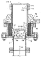
- An exhaust device for a diesel engine thus arranged is characterized in that, as exemplified in Figs. 2 , 3 and 6, the gas generator 3 is provided with a catalyst chamber 51 which contains a catalyst 4 and in which catalyst-combustion heat is produced, the catalyst chamber 51 being arranged along an external periphery of a peripheral wall 1a of the exhaust route 1.
- the gas generator 3 is provided with a catalyst chamber 51 which contains a catalyst 4 and in which catalyst-combustion heat is produced.
- the catalyst chamber 51 is arranged along an external periphery of a peripheral wall 1a of the exhaust route 1. Therefore, the catalyst chamber 51 avoids the problem that the heat in the exhaust route 1 is radiated from the peripheral wall 1a of the exhaust route 1 to result in retaining the flammable gas 7 at a high temperature. This assures the combustion of the flammable gas 7 in the exhaust route 1.
- the exhaust device can be made compact.
- the catalyst chamber 51 is disposed along the external periphery of the peripheral wall 1a of the exhaust route1. In consequence, it is possible to omit or shorten the piping from the flammable-gas flow outlet 9 to the exhaust route 1.
- the catalyst chamber 51 is arranged along the whole region in a peripheral direction of the peripheral wall 1a. Therefore, it has the important function of inhibiting the heat radiation from the exhaust-route peripheral wall 1a, so to promote the burning of the flammable gas 7 in the exhaust route 1.
- the catalyst chamber 51 is arranged along the whole periphery of the exhaust-route peripheral wall 1a, so that the exhaust device can be made more compact.
- the flammable gas 7 heated in the catalyst chamber 51 is mixed with part 10a of the exhaust gas 10 in a flammable-gas mixing passage 15, and an ignition means 45 can ignite the flammable gas 7.
- the flammable gas 7 has its temperature hardly lowered when compared with the event of mixing the whole amount of the exhaust gas 10 with the flammable gas 7 and therefore the flammable gas 7 can be surely ignited by the ignition means 45. This can more assuredly burn the flammable gas 7 in the exhaust route 1.
- the flammable-gas mixing passage 15 has a sectional area varying along a flow direction. This changes the flow speed of the mixed gas 67, which comprises the flammable gas 7 and part 10a of the exhaust gas 10, within the flammable-gas mixing passage 15 to generate a portion where the flame propagation speed of the mixed gas 67 becomes lower than its passing speed. Due to this fact, the combustion flame produced within the flammable-gas mixing passage 15 hardly disappears, and again the burning of the flammable gas 7 is promoted.
- the flammable-gas mixing passage 15 has a sectional area increasing toward the downstream.
- the mixed gas 67 passes at a lower speed as it flows toward the downstream, thereby assuredly retaining the combustion flame produced upstream of the flammable-gas mixing passage 15: This promotes the burning of the flammable gas 7.
- a cylindrical wall 1d is provided inside the exhaust route 1.
- a heat-insulation space 1e is defined between the cylindrical wall 1 d and the peripheral wall 1 a of the exhaust route 1 and between the cylindrical wall 1d and the outlet-side flange 1c.
- the cylindrical wall 1d and the heat-insulation space 1e shield the heat of the exhaust gas 10 and the flammable gas 7. This inhibits the overheating of the outlet-side flange 1c and the inlet-side flange 11 c by the above-mentioned heat, whereby there is an effective seal at the connection portion between the outlet-side flange 1 c and the inlet-side flange 11 c.
- an ignition means 45 is an igniting electric heater 45a. This avoids the phenomenon that cause such an incident that carbon adhering to the electrode prevents the production of an ignition spark for igniting the flammable gas 7 like a spark plug. Thus mis-ignition of the flammable gas 7 hardly occurs in the exhaust route 1.
- the exhaust-route peripheral wall 1 a with the catalyst chamber 51 arranged along the same serves as a heat-radiation wall 8 which is used as the ignition means 45. This promotes the burning of the flammable gas 7 in the exhaust route 1 assuredly.
- the catalyst-combustion heat produced in the catalyst chamber 51 can be conveyed through a heat conductor 58 to a fuel nozzle 53. This accelerates the vaporization of the liquid fuel 6 whereby uniformly mixed air 56 is supplied to the catalyst chamber 51 with the result of increasing the efficiency of the gas generation.
- the catalyst-combustion heat produced in the catalyst chamber 51 can be conveyed through the heat conductor 58 to the fuel nozzle 53. While the catalyst-combustion heat is being generated, the catalyst-combustion heat can be utilized for producing uniformly mixed gas 56.
- the heat conductor 58 has an exposed surface 58a disposed at a position opposite to an inlet 51a of the catalyst chamber 51 and the liquid fuel 6 which has flowed from an outlet 57 of a mixing chamber 55 is brought into contact with the exposed surface 58a of the heat conductor 58. Accordingly, the liquid fuel 6 still remaining unvaporised in the mixing chamber 55 can be vaporized with the exposed surface 58a of the heat conductor 58. This accelerates the vaporization of the liquid fuel 6 and supplies uniform mixed gas 56 to the catalyst chamber 51, thereby enhancing the efficiency of the gas generation in the catalyst chamber 51.
- an electric heater 65 is brought into contact with the heat conductor 58 so as to heat the heat conductor 58 upon commencing the generation of the flammable gas 7. Therefore, upon the commencement of the generation of the flammable gas during which the catalyst-combustion heat is not produced, the electric heater 65 can heat the heat conductor 58. This makes it possible to promptly commence the gas generation in the catalyst chamber 51.
- the substrates 4a of the catalyst 4 form the mixed gas passage in the shape of cubic mesh. This can reduce the volume of the catalyst chamber 51 so as to render the exhaust device compact.
- pellet-like substrates are employed for the substrates 4a, and a gap between adjacent substrates 4a, 4a defines the mixed gas passage of cubic-mesh shape. Therefore, it suffices if the catalyst 4 fills the catalyst chamber 51, in order to form the mixed gas passage of cubic-mesh shape.
- the pellet-like substrate is used for the substrate 4 allows an easy charging of the catalyst chamber 51 with the catalyst.
- the substrate 4a is highly resistant to heat.
- the substrates 4a are mixed with metal springs 66 and the resulting mixture is housed in the catalyst chamber 51 so that the metal springs 66 serve as cushions for the substrates 4a. In consequence, the likelihood of breakage of the substrates 4a by vibration is substantially prevented.
- fuel from a fuel reservoir 5a of the diesel engine is used for the liquid fuel 6.
- air from a supercharger 39 is utilized as the air 44.
- the fuel reservoir 5a and the supercharger 39 of the diesel engine with the supercharger serve as the fuel supply source and the air supply source of the gas generator 3; this reduces the cost of the exhaust device.
- the liquid fuel 6 is vaporized in the catalyst chamber 51 so as to convert the liquid fuel 6 into the flammable gas 7. So when compared with the partial oxidation or the like reaction, there is only a small variation of the component ratio of the flammable gas 7 and therefore the combustion heat of the flammable gas 7 is stably obtained.
- the liquid fuel 6 is partially oxidized in the catalyst chamber 51 to reform the liquid fuel 6 into the flammable gas 7 containing carbon monoxide and hydrogen.
- the flammable gas 7 is ignited even at a relatively low temperature. Further, even if the exhaust gas 10 has a low temperature, the flammable gas 7 can be burnt.
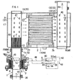
- Figs. 1 to 4 show an exhaust device for a diesel engine in accordance with a first embodiment of the present invention.
- Fig. 5 shows an exhaust device for a diesel engine in accordance with a second embodiment of the invention.
- liquid fuel 6 is supplied from a liquid-fuel supply source 5 to a gas generator 3, which converts the liquid fuel 6 to flammable gas 7.
- the gas generator 3 has a flammable-gas flow outlet 9 which is communicated with an exhaust route 1 upstream of a diesel-particulate-filter 2.
- the flammable gas 7 flowing out from the flammable-gas flow outlet 9 is burnt with oxygen in exhaust gas 10 to produce combustion heat.
- the thus produced combustion heat heats the exhaust gas 10 and the exhaust gas 10 thus heated can burn exhaust-gas fine particles remaining at the filter 2.
- This exhaust device is connected to an outlet 36 of an exhaust manifold of the diesel engine.
- the diesel-particulate-filter 2 is generally termed "DPF" and is formed into a honeycomb structure made of a ceramic. Further, the diesel-particulate-filter 2 supports an oxidation catalyst or may support a Nox-occlusion catalyst.
- the gas generator 3 is provided with a catalyst chamber 51, which houses a catalyst 4 and in which the catalyst-combustion heat is produced.
- the catalyst chamber 51 is arranged along an external periphery of a peripheral wall 1a of the exhaust route 1. Additionally, this catalyst chamber 51 is disposed over an entire area in a peripheral direction of the peripheral wall 1a of the exhaust route 1.
- a partition wall 14 within the exhaust-route peripheral wall 1a with the catalyst chamber 51 arranged along the same.
- This partition wall 14 divides an interior area of the exhaust route 1 into a flammable-gas mixing passage 15 and an exhaust-gas passage 16.
- the flammable-gas mixing passage 15 has a starting end 15a with which the flammable-gas flow outlet 9 is communicated and has an terminal end 15b at which an ignition means 45 is arranged. Owing to the above arrangement, the flammable gas 7 heated within the catalyst chamber 51 is mixed with part 10a of the exhaust gas 10 in the flammable-gas mixing passage 15, and the ignition means 45 can ignite the flammable gas 7.
- the ignition means 45 may be disposed at a predetermined portion in a region extending from an interior area of the flammable-gas mixing passage 15 to just after its terminal end portion 15b.
- the ignition means 45 is an igniting electric heater 45a and concretely uses a sheath-type glow plug.
- the sheath- type glow plug comprises a heat-resistant tube housing a heating coil.
- the partition wall 14 is in the shape of a circular cylinder and has a leading end formed in the shape of a truncated-cone. This leading end partitions an interior area of the exhaust route 1 into the external flammable-gas mixing passage 15 and the internal exhaust-gas passage 16.
- the partition wall 14 is provided with a plurality of exhaust-gas diverging ports 16a via which part 10a of the exhaust gas 10 passes through the exhaust-gas passage 16, and the part 10a of the exhaust gas 10 diverges into the flammable-gas mixing passage 15.
- the cylindrical wall 1b is in the shape of a circular cylinder.
- the flammable-gas mixing passage 15 has a sectional area varying along a flow direction and increasing gradually in the downstream direction.
- an oxidation catalyst 12 is arranged downstream of the ignition means 45 and upstream of the filter 2.
- an outlet-side flange 1 c is provided at an end portion downstream of the exhaust-route peripheral wall 1 a and an inlet-side flange 11c is positioned at a case 11 for housing the filter 2.
- the outlet-side flange 1c of the exhaust-route peripheral wall 1a being connected to the inlet-side flange 11c of the filter-housing case 11, the cylindrical wall 1 d is provided inside the exhaust route 1 and a heat-insulation space 1e is defined between the cylindrical wall 1d and the exhaust-route peripheral wall 1a as well as between the cylindrical wall 1d and the outlet-side flange 1c.
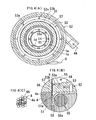
- a mixer 52 is arranged above the catalyst chamber 51, namely on a side of an inlet 51 a of the catalyst chamber 51 and as shown in Fig. 4(B) , the liquid fuel 6 supplied from a fuel nozzle 53 is mixed with air 44 in a mixing chamber 55 to provide mixed air 56.
- this mixed air 56 is fed from an outlet 57 of the mixing chamber 55 to the inlet 51a of the catalyst chamber 51, the catalyst-combustion heat produced in the catalyst chamber 51 can be conveyed to the fuel nozzle 53 through a heat conductor 58.
- the heat conductor 58 has an exposed surface 58a arranged at a position opposite to the inlet 51 a of the catalyst chamber 51 below the outlet 57 of the mixing chamber 55.
- the mixing chamber 55 is annularly formed and the fuel nozzle 53 has a plurality of fuel injection ports 53a provided by its own openings. The ports are peripherally regularly at a bottom portion of the mixing chamber 55.
- the mixing chamber 55 has a bottom portion provided with a slant surface 53b inclined downwardly from each of the injection ports 53a.
- This slant surface 53b has a downward terminal end formed with an annular outlet 57 of the mixing chamber 55.
- the liquid fuel 6 injected from the plurality of fuel injection ports 53a mixes with the air 44 circulating in the mixing chamber 51 while flowing along the slant surfaces 53b to constitute the mixed air 56 which flows from the outlet 57 of the mixer chamber 55 toward the inlet 51a of the combustion chamber as shown in Fig. 4(B) .
- the substrates 4a of the catalyst 4 form the mixed air passage of cubic-mesh shape.
- a ceramic is used for the substrates 4a, an internal structure of which forms the mixed air passage of cubic-mesh shape.
- a pellet-like substrate for example a pellet-like ceramic
- a gap between adjacent substrates 4a, 4a may define the mixed air passage of cubic-mesh shape.
- the substrates 4a are mixed with metal springs 66 and the resulting mixture is housed in the catalyst chamber 51 to make the metal springs 66 serve as cushions for the substrates 4a.
- Alumina pellets may be employed for the substrate 4a.
- the metal springs 66 a barrel type is advantageous. This is because it is easily mixed with the alumina pellet owing to their similarity of shape with the alumina pellets.
- the metal springs 66 may be formed basically, which may be tungsten subjected to gold-plating to inhibit oxidation.
- a liquid-fuel supply passage 46 is provided with a liquid-fuel valve 40 and an air supply passage 38 is formed with an air valve 41.
- Each of the valves 40 and 41 is associated via a controller 42 with a back-pressure sensor 43. In the event that the filter 2 is clogged with exhaust-gas fine particles, the back pressure increases.
- the controller 42 opens the liquid-fuel valve 40 and the air valve 41, thereby supplying the liquid fuel 6 and the air 44 to the gas generator 3 so as to vaporize the liquid fuel 6 in the catalyst chamber 51.
- the liquid fuel 6 is converted to the flammable gas 7 which is fed into the exhaust route 1.
- the controller 42 energizes the electric heater 65 and after the elapse of a predetermined period of time, a timer stops the energization of the electric heater 65.
- the liquid fuel 6 is vaporized in the catalyst chamber 51, thereby converting the liquid fuel 6 to the flammable gas 7.
- the catalyst 4 in the catalyst chamber 51 is an oxidation catalyst that partly oxidizes the liquid fuel 6 and the resulting oxidation heat vaporizes the residual liquid fuel 6.
- the mixing ratio of the air 44 to the liquid fuel 6, namely the air/fuel ratio O/C, is set within a range of 0.4 to 0.8, preferably about around 0.6.
- the catalyst component is platinum series.
- the liquid fuel 6 may be reformed. More specifically, the liquid fuel 6 may be partially oxidized in the catalyst chamber 51, thereby reforming the liquid fuel 6 to flammable gas 7 containing carbon monoxide and hydrogen.
- a partial-oxidation catalyst is used instead of the oxidation catalyst.
- the mixing ratio of the air 44 to the liquid fuel 6, namely the air/fuel ratio O/C is set within the range of 1.0 to 1.6, preferably about 1.3.
- the catalyst component is palladium series, rhodium series or the like.
- a cylindrical filter-housing case 11 provided at its opposite ends with end walls 17 and 18 is used.
- an axial direction of this filter-housing case 11 is considered to be a front and rear direction, one side on which an inlet 2a of the filter 2 is situated is the front and the other side on which an outlet 2b thereof is present is the rear.
- an exhaust-gas inlet chamber 19 is arranged in front of the filter 2 and an exhaust-gas outlet chamber 20 is disposed at the rear of the filter 2, respectively.
- An exhaust-gas inlet pipe 21 and an exhaust-gas outlet pipe 22 communicate with the exhaust-gas inlet chamber 19 and the exhaust-gas outlet chamber 20, respectively.
- the exhaust-gas inlet pipe 21 is inserted into the exhaust-gas inlet chamber 19 along a radial direction of the filter-housing case 11.
- an exhaust-gas pipe 1b Provided between this exhaust-gas inlet pipe 21 and the exhaust-gas outlet 36 of the exhaust manifold is an exhaust-gas pipe 1b.
- the catalyst chamber 51 is arranged along an outer periphery of the exhaust-gas pipe 1 b.
- an exhaust muffler 28 is employed for the filter-housing case 11.
- the exhaust-gas inlet chamber 19 is constructed by a first expansion chamber 29 and the exhaust-gas outlet chamber 20 is formed from a final expansion chamber 30.
- the exhaust-gas inlet pipe 21 is constructed by an exhaust lead-in pipe 31 of the first expansion chamber 29 and the exhaust-gas outlet pipe 22 is formed from an exhaust lead-out pipe 32 of the final expansion chamber 30.
- the liquid fuel 6 and the air 44 are supplied to the gas generator 3.
- the liquid fuel 6 mixes with the air 44 to result in the mixed air 56 which flows into the catalyst chamber 51.
- Part of the liquid fuel 6 is oxidized (burnt by catalyst) within the catalyst chamber 51 to generate oxidation (combustion) heat.
- This oxidation (combustion) heat vaporizes the remaining liquid fuel 6 to produce flammable gas 7 of a high temperature.
- This high-temperature flammable gas 7, as shown in Fig. 2 is fed from the flammable-gas flow outlet 9 into the flammable-gas mixing passage 15.
- the part 10a of the exhaust gas 10 which passes through the exhaust route 1 flows into the flammable-gas mixing passage 15 to be mixed with the high-temperature flammable gas 7.
- the flammable gas 7 is ignited by its heat
- the part 10a of the exhaust gas 10 has a lower temperature, it is ignited by the heat resulting from exothermic reaction of the igniting electric heater 4.
- the flammable gas 7 is oxidized (burnt) by the oxygen in the part 10a of the exhaust gas 10 mixed as above to generate oxidation (combustion) heat which heats the part 10a of the exhaust gas 10 mixed.
- the remaining part 10b of the exhaust gas 10 passes through the exhaust-gas passage 16 and is mixed with the heated part 10a of the exhaust gas 10 to be heated.
- the flammable gas 7 that has not be burnt by the ignition of the igniting electric heater 45a is burnt by being oxidized when passing through the oxidation catalyst 12 to increase the temperature of the exhaust gas 10.
- the exhaust gas 10 flows from the oxidation catalyst 12 as indicated by an arrow 60 and besides from an outlet hole 47 of the exhaust lead-in pipe 31 and then flows into the first expansion chamber 29. Thereafter, the exhaust gas 10 flows into the filter 2 through its inlet 2a and passes through an interior area of the filter 2. The exhaust gas 10 that has passed through the interior area of the filter 2 flows into the final expansion chamber 30 through the outlet 2b of the filter 2 as indicated by arrows 63 and then flows into the exhaust lead-out pipe 32 from the inlet hole 48 thereof. Thereafter, it flows out of the exhaust lead-out pipe 32 as indicated by an arrow 64.
- a second embodiment is different from the first embodiment in the following respects.
- a heat radiation wall 8 is utilized for the ignition means 45. More specifically, the exhaust-passage peripheral wall 1 a with the catalyst chamber 51 arranged along the same serves as the heat radiation wall 8.
- the flammable gas 7 heated within the catalyst chamber 51 is mixed with the exhaust gas 10 in the exhaust route 1, and the heat radiation wall 8 radiates the catalyst-combustion heat produced within the catalyst chamber 51 to the mixed gas, thereby enabling the heat radiation wall 8 to serve as the ignition means 45 so as to be able to ignite the flammable gas 7.
- This construction can assuredly burn the flammable gas in the exhaust route 1.
- the catalyst chamber 51 is arranged along the entire area in the peripheral direction of the peripheral wall 1a of the exhaust route 1 and the heat radiation wall 8 is formed over the whole region in the peripheral direction of the peripheral wall 1 a of the exhaust route 1.
- a partition wall 14 is provided in the exhaust-route peripheral wall 1a with the catalyst chamber 51 arranged along the same and divides the interior area of the exhaust route 1 into the flammable-gas mixing passage 15 and the exhaust-gas passage 16.
- the flammable-gas mixing passage 15 has an inlet 15a with which the flammable-gas flow outlet 9 communicates and has the heat radiation wall 8 arranged in its interior.
- the heat radiation wall 8 can ignite the flammable gas 7 while the flammable gas 7 heated in the catalyst chamber 51 is being mixed with part 10a of the exhaust gas 10 in the flammable-gas mixing passage 15.
Landscapes
- Engineering & Computer Science (AREA)
- Chemical & Material Sciences (AREA)
- Combustion & Propulsion (AREA)
- Mechanical Engineering (AREA)
- General Engineering & Computer Science (AREA)
- Chemical Kinetics & Catalysis (AREA)
- Health & Medical Sciences (AREA)
- Toxicology (AREA)
- Processes For Solid Components From Exhaust (AREA)
- Exhaust Gas After Treatment (AREA)
Claims (17)
- Dispositif d'échappement pour un moteur diesel qui alimente du carburant liquide (6) d'une source d'alimentation de carburant liquide (5) à un générateur de gaz (3) qui transforme le carburant liquide (6) en gaz inflammable (7), une sortie d'écoulement de gaz inflammable (9) du générateur de gaz (3) communiquant avec une voie d'échappement (1) en amont d'un filtre à particules diesel (2), le gaz inflammable (7) qui sort en s'écoulant de la sortie d'écoulement de gaz inflammable (9) étant brûlé avec de l'oxygène dans le gaz d'échappement (10) pour générer de la chaleur de combustion, le gaz d'échappement (10) chauffé par la chaleur de combustion pouvant brûler les fines particules de gaz d'échappement qui restent au niveau de filtre (2), dans lequel le générateur de gaz (3) est équipé d'une chambre de catalyseur (51) qui loge un catalyseur (4) et à l'intérieur duquel la chaleur de combustion de catalyseur est produite, la chambre de catalyseur (51) étant agencée le long d'une périphérie externe d'une paroi périphérique (1a) de la voie d'échappement (1), caractérisé en ce qu'une paroi de séparation (14) est prévue à l'intérieur de la paroi périphérique (1a) de la voie d'échappement (1) et divise un intérieur de la voie d'échappement (1) en un passage de mélange de gaz inflammable (15) et un passage de gaz d'échappement (16), une parie d'extrémité de départ (15a) du passage de mélange de gaz inflammable (15) communiquant avec la sortie d'écoulement de gaz inflammable (9), des moyens d'allumage (45) étant agencés au niveau d'une partie prédéterminée dans une région s'étendant à partir d'une zone intérieure du passage de mélange de gaz inflammable (15) jusqu'à après sa partie d'extrémité terminale (15b), le gaz inflammable (7) chauffé à l'intérieur de la chambre de catalyseur (51) est mélangé avec une partie (10a) du gaz d'échappement (10) dans le passage de mélange de gaz inflammable (15), et les moyens d'allumage (45) allument le gaz inflammable (7).
- Dispositif d'échappement selon la revendication 1, dans lequel la chambre de catalyseur (51) est agencée sur une surface entière dans une direction périphérique de la paroi périphérique (1a) de la voie d'échappement (1).
- Dispositif d'échappement selon la revendication 1 ou 2, dans lequel le passage de mélange de gaz inflammable (15) a une aire de section variant le long d'une direction d'écoulement.
- Dispositif d'échappement selon la revendication 3, dans lequel le passage de mélange de gaz inflammable (15) à l'aire de section qui augmente progressivement vers l'aval.
- Dispositif d'échappement selon l'une quelconque des revendications 1 à 4, dans lequel un rebord du côté de la sortie (1c) est prévu au niveau d'une partie d'extrémité en aval de la paroi périphérique de voie d'échappement (1a) et un rebord du côté de l'entrée (11c) est prévu au niveau d'un boîtier (11) qui loge un filtre (2) et lorsque l'on raccorde le rebord du côté de la sortie (1c) de la paroi périphérique de voie d'échappement (1a) au rebord du côté de l'entrée (11c) du boîtier de logement de filtre (11), une paroi cylindrique (1d) est prévue à l'intérieur de la voie d'échappement (1) et un espace d'isolation thermique (1e) est défini entre la paroi cylindrique (1d) et la paroi périphérique (1a) de la voie d'échappement (1) ainsi qu'entre la paroi cylindrique (1d) et le rebord du côté de la sortie (1c).
- Dispositif d'échappement selon l'une quelconque des revendications 1 à 5, dans lequel les moyens d'allumage (45) sont un dispositif de chauffage électrique de mise à feu (45a).
- Dispositif d'échappement selon l'une quelconque des revendications 1 à 5, dans lequel la paroi périphérique de voie d'échappement (1a) avec la chambre de catalyseur (51) agencée le long de cette dernière sert en tant que paroi de rayonnement de chaleur (8) qui est utilisée pour les moyens d'allumage (45).
- Dispositif d'échappement selon l'une quelconque des revendications 1 à 7, dans lequel un catalyseur d'oxydation (12) est agencé en aval des moyens d'allumage (45) et en amont du filtre (2).
- Dispositif d'échappement selon l'une quelconque des revendications 1 à 8, dans lequel un mélangeur (52) est disposé sur un côté d'une entrée (51a) de la chambre de catalyseur (51) et le carburant liquide (6) alimenté à partir d'une buse de carburant (53) est mélangé avec de l'air (44) dans une chambre de mélange (55) et lorsque l'air ainsi mélangé (56) est alimenté à partir de la sortie (57) de la chambre de mélange (55) à l'entrée (51a) de la chambre de catalyseur (51), la chaleur de combustion de catalyseur produite dans la chambre de catalyseur (51) est transportée vers la buse de carburant (53) par un conducteur de chaleur (58).
- Dispositif d'échappement selon la revendication 9, dans lequel le conducteur de chaleur (58) a une surface exposée (58a) agencée dans une position opposée à l'entrée (51a) de la chambre de catalyseur (51) et le carburant liquide (6) qui s'est écoulé par la sortie (57) de la chambre de mélange (55) est amené en contact avec la surface exposée (58a) du conducteur de chaleur (58).
- Dispositif d'échappement selon la revendication 10, dans lequel un dispositif de chauffage électrique (65) est amené en contact avec le conducteur de chaleur (58) afin de chauffer le conducteur de chaleur (58) lors du commencement de la génération du gaz inflammable.
- Dispositif d'échappement selon l'une quelconque des revendications 1 à 11, dans lequel un substrat (4a) d'un catalyseur (4) forme un passage d'air mélangé en forme de maille cubique.
- Dispositif d'échappement selon la revendication 12, dans lequel un substrat en forme de boulettes est utilisé pour le substrat (4a) et un espace entre les substrats (4a) et (4a) adjacents définit le passage d'air mélangé en forme de maille cubique.
- Dispositif d'échappement selon la revendication 12, dans lequel lorsqu'une céramique en forme de boulettes est utilisée pour le substrat (4a) et un espace entre les substrats (4a) et (4a) adjacents définit le passage d'air mélangé en forme de maille cubique, les substrats (4a), (4a) sont mélangés avec des ressorts en métal (66) et le mélange ainsi formé est logé dans la chambre de catalyseur (51), le ressort en métal (66) servant de coussinnet pour le substrat (4a).
- Dispositif d'échappement selon l'une quelconque des revendications 1 à 14, dans lequel le carburant provenant d'un réservoir de carburant (5a) du moteur diesel est utilisé pour le carburant liquide (6) et lors du mélange de l'air (44) dans le carburant liquide (6), l'air (44) provenant d'un compresseur volumétrique (39) est utilisé pour l'air (44).
- Dispositif d'échappement selon l'une quelconque des revendications 1 à 15, dans lequel le carburant liquide (6) est vaporisé dans la chambre de catalyseur (51), transformant ainsi le carburant liquide (6) en gaz inflammable (7).
- Dispositif d'échappement selon l'une quelconque des revendications 1 à 15, dans lequel le carburant liquide (6) est partiellement oxydé dans la chambre de catalyseur (51), en reformant ainsi le carburant liquide (6) en gaz inflammable (7) contenant du monoxyde de carbone et de l'hydrogène.
Applications Claiming Priority (2)
| Application Number | Priority Date | Filing Date | Title |
|---|---|---|---|
| JP2007211781 | 2007-08-15 | ||
| JP2007222730 | 2007-08-29 |
Publications (2)
| Publication Number | Publication Date |
|---|---|
| EP2025890A1 EP2025890A1 (fr) | 2009-02-18 |
| EP2025890B1 true EP2025890B1 (fr) | 2010-11-10 |
Family
ID=39816783
Family Applications (1)
| Application Number | Title | Priority Date | Filing Date |
|---|---|---|---|
| EP08250688A Expired - Fee Related EP2025890B1 (fr) | 2007-08-15 | 2008-02-28 | Dispositif d'échappement pour moteur diesel |
Country Status (6)
| Country | Link |
|---|---|
| US (1) | US8091353B2 (fr) |
| EP (1) | EP2025890B1 (fr) |
| JP (1) | JP4794595B2 (fr) |
| KR (1) | KR101406468B1 (fr) |
| CN (1) | CN101368500B (fr) |
| DE (1) | DE602008003363D1 (fr) |
Families Citing this family (22)
| Publication number | Priority date | Publication date | Assignee | Title |
|---|---|---|---|---|
| JP4677418B2 (ja) * | 2007-03-05 | 2011-04-27 | 株式会社クボタ | ディーゼルエンジンの排気装置 |
| JP5167215B2 (ja) * | 2009-09-02 | 2013-03-21 | 株式会社クボタ | ディーゼルエンジンの排気処理装置 |
| JP5210999B2 (ja) * | 2009-09-02 | 2013-06-12 | 株式会社クボタ | ディーゼルエンジンの排気処理装置 |
| JP5167216B2 (ja) * | 2009-09-02 | 2013-03-21 | 株式会社クボタ | ディーゼルエンジンの排気処理装置 |
| CN102032030B (zh) * | 2009-09-25 | 2015-04-22 | 中国第一汽车集团公司 | 一种汽车尾气催化还原后处理器的复合单元 |
| JP5353822B2 (ja) | 2009-09-30 | 2013-11-27 | 株式会社Ihi | 着火装置 |
| US8656708B2 (en) * | 2011-01-31 | 2014-02-25 | Tenneco Automotive Operating Company Inc. | Coaxial inlet and outlet exhaust treatment device |
| JP2012188974A (ja) * | 2011-03-09 | 2012-10-04 | Kubota Corp | エンジンの排気処理装置 |
| JP5462822B2 (ja) * | 2011-03-09 | 2014-04-02 | 株式会社クボタ | エンジンの排気処理装置 |
| JP5520860B2 (ja) * | 2011-03-09 | 2014-06-11 | 株式会社クボタ | エンジンの排気処理装置 |
| JP5462823B2 (ja) * | 2011-03-09 | 2014-04-02 | 株式会社クボタ | エンジンの排気処理装置 |
| JP5878364B2 (ja) * | 2011-12-26 | 2016-03-08 | フタバ産業株式会社 | 排気処理装置 |
| JP5750389B2 (ja) * | 2012-03-15 | 2015-07-22 | 株式会社クボタ | エンジンの排気処理装置 |
| JP5750390B2 (ja) * | 2012-03-15 | 2015-07-22 | 株式会社クボタ | エンジンの排気処理装置 |
| JP5878889B2 (ja) * | 2012-12-26 | 2016-03-08 | 株式会社クボタ | エンジンの排気処理装置 |
| CN103266940A (zh) * | 2013-05-24 | 2013-08-28 | 安徽艾可蓝节能环保科技有限公司 | 一种柴油机尾气高温隔热和增温装置 |
| DE102013219640A1 (de) * | 2013-09-27 | 2015-04-02 | Eberspächer Exhaust Technology GmbH & Co. KG | Abgasbehandlungseinrichtung |
| WO2016109323A1 (fr) | 2014-12-31 | 2016-07-07 | Cummins Emission Solutions, Inc. | Système de post-traitement de module unique monobloc |
| CN107106960A (zh) | 2014-12-31 | 2017-08-29 | 康明斯排放处理公司 | 单模块集成式后处理模块 |
| CN107109993B (zh) * | 2014-12-31 | 2019-08-20 | 康明斯排放处理公司 | 紧凑的侧式出入口排气后处理系统 |
| DE102015103303B3 (de) * | 2015-03-06 | 2016-09-01 | Tenneco Gmbh | Mix Box |
| JP6795485B2 (ja) * | 2017-12-28 | 2020-12-02 | 株式会社クボタ | エンジンの排気処理装置 |
Family Cites Families (12)
| Publication number | Priority date | Publication date | Assignee | Title |
|---|---|---|---|---|
| JPS5820918A (ja) * | 1981-07-28 | 1983-02-07 | Nissan Motor Co Ltd | 排気浄化装置 |
| JPS60135612A (ja) * | 1983-12-22 | 1985-07-19 | Nissan Motor Co Ltd | 内燃機関の排気微粒子処理装置 |
| JPH08200046A (ja) * | 1995-01-20 | 1996-08-06 | Nissan Diesel Motor Co Ltd | エンジンの排気浄化装置 |
| DE19504183A1 (de) * | 1995-02-09 | 1996-08-14 | Eberspaecher J | Brenner zur thermischen Regeneration eines Partikelfilters in einem Abgasnachbehandlungssystem eines Verbrennungsmotors, insbesondere Dieselmotors |
| JP2002155728A (ja) | 2000-11-21 | 2002-05-31 | S & S Engineering:Kk | パーティキュレート・フィルタ |
| WO2004046514A1 (fr) * | 2002-11-15 | 2004-06-03 | Catalytica Energy Systems, Inc. | Dispositifs et procedes pour reduire les emissions de nox de moteurs a melange pauvre |
| EP1479883A1 (fr) | 2003-05-10 | 2004-11-24 | Universität Stuttgart | Procédé et dispositif de purification des gaz d'échappement |
| JP4328647B2 (ja) | 2004-03-12 | 2009-09-09 | 株式会社クボタ | 排気浄化器の再生装置 |
| KR100548451B1 (ko) | 2005-07-22 | 2006-01-31 | 한국기계연구원 | 디젤엔진매연여과장치 재생용 내염버너 |
| WO2007037652A1 (fr) | 2005-09-30 | 2007-04-05 | Korea Institute Of Energy Research | Dispositif de chauffage pour gaz d'echappement dans un moteur a combustion interne |
| JP4538429B2 (ja) | 2006-02-09 | 2010-09-08 | 株式会社クボタ | ディーゼルエンジンの排気装置 |
| JP4674189B2 (ja) | 2006-07-13 | 2011-04-20 | 株式会社クボタ | ディーゼルエンジンの排気装置 |
-
2008
- 2008-02-28 EP EP08250688A patent/EP2025890B1/fr not_active Expired - Fee Related
- 2008-02-28 DE DE602008003363T patent/DE602008003363D1/de active Active
- 2008-03-03 KR KR1020080019586A patent/KR101406468B1/ko active IP Right Grant
- 2008-03-14 CN CN200810085394XA patent/CN101368500B/zh not_active Expired - Fee Related
- 2008-03-14 US US12/048,759 patent/US8091353B2/en not_active Expired - Fee Related
- 2008-03-28 JP JP2008085715A patent/JP4794595B2/ja not_active Expired - Fee Related
Also Published As
| Publication number | Publication date |
|---|---|
| CN101368500A (zh) | 2009-02-18 |
| KR101406468B1 (ko) | 2014-06-13 |
| US8091353B2 (en) | 2012-01-10 |
| DE602008003363D1 (de) | 2010-12-23 |
| KR20090017966A (ko) | 2009-02-19 |
| CN101368500B (zh) | 2012-04-04 |
| JP4794595B2 (ja) | 2011-10-19 |
| JP2009074533A (ja) | 2009-04-09 |
| EP2025890A1 (fr) | 2009-02-18 |
| US20090044522A1 (en) | 2009-02-19 |
Similar Documents
| Publication | Publication Date | Title |
|---|---|---|
| EP2025890B1 (fr) | Dispositif d'échappement pour moteur diesel | |
| JP4677418B2 (ja) | ディーゼルエンジンの排気装置 | |
| JP4674189B2 (ja) | ディーゼルエンジンの排気装置 | |
| EP2119881B1 (fr) | Dispositif d'échappement pour moteur diesel | |
| US20030200742A1 (en) | Apparatus and method for regenerating a particulate filter of an exhaust system of an internal combustion engine | |
| EP1784889A2 (fr) | Reformage de carburant hydrocarbone atomise non vaporise | |
| WO2020246302A1 (fr) | Système de combustion d'ammoniac | |
| US20150082777A1 (en) | Exhaust purification device burner | |
| US20050198900A1 (en) | Method and apparatus for fuel/air preparation for a hydrocarbon reformer | |
| JP4538429B2 (ja) | ディーゼルエンジンの排気装置 | |
| US7814746B2 (en) | Exhaust device for a diesel engine | |
| JP2008232061A (ja) | ディーゼルエンジンの排気装置 | |
| JP4794594B2 (ja) | ディーゼルエンジンの排気装置 | |
| EP1961931B1 (fr) | Dispositif d'échappement pour moteur diesel | |
| JP5009593B2 (ja) | 燃焼装置 | |
| JP2013542375A (ja) | 燃料改質装置 | |
| JP7380300B2 (ja) | 燃焼器、改質装置及び改質システム | |
| JP5135123B2 (ja) | 燃焼装置 | |
| KR101318014B1 (ko) | 디젤엔진의 배기장치 | |
| JP6795486B2 (ja) | エンジンの排気処理装置 | |
| AU2022310752A1 (en) | Reforming device | |
| JP2019120132A (ja) | エンジンの排気処理装置 | |
| JP2019120136A (ja) | エンジンの排気処理装置 | |
| JP5526907B2 (ja) | 火花点火エンジンシステム | |
| JP2019120135A (ja) | エンジンの排気処理装置 |
Legal Events
| Date | Code | Title | Description |
|---|---|---|---|
| PUAI | Public reference made under article 153(3) epc to a published international application that has entered the european phase |
Free format text: ORIGINAL CODE: 0009012 |
|
| AK | Designated contracting states |
Kind code of ref document: A1 Designated state(s): AT BE BG CH CY CZ DE DK EE ES FI FR GB GR HR HU IE IS IT LI LT LU LV MC MT NL NO PL PT RO SE SI SK TR |
|
| AX | Request for extension of the european patent |
Extension state: AL BA MK RS |
|
| 17P | Request for examination filed |
Effective date: 20090728 |
|
| AKX | Designation fees paid |
Designated state(s): DE FR GB IT |
|
| 17Q | First examination report despatched |
Effective date: 20091116 |
|
| GRAP | Despatch of communication of intention to grant a patent |
Free format text: ORIGINAL CODE: EPIDOSNIGR1 |
|
| GRAS | Grant fee paid |
Free format text: ORIGINAL CODE: EPIDOSNIGR3 |
|
| GRAA | (expected) grant |
Free format text: ORIGINAL CODE: 0009210 |
|
| AK | Designated contracting states |
Kind code of ref document: B1 Designated state(s): DE FR GB IT |
|
| REG | Reference to a national code |
Ref country code: GB Ref legal event code: FG4D |
|
| REF | Corresponds to: |
Ref document number: 602008003363 Country of ref document: DE Date of ref document: 20101223 Kind code of ref document: P |
|
| PLBE | No opposition filed within time limit |
Free format text: ORIGINAL CODE: 0009261 |
|
| STAA | Information on the status of an ep patent application or granted ep patent |
Free format text: STATUS: NO OPPOSITION FILED WITHIN TIME LIMIT |
|
| 26N | No opposition filed |
Effective date: 20110811 |
|
| REG | Reference to a national code |
Ref country code: DE Ref legal event code: R097 Ref document number: 602008003363 Country of ref document: DE Effective date: 20110811 |
|
| REG | Reference to a national code |
Ref country code: FR Ref legal event code: PLFP Year of fee payment: 9 |
|
| REG | Reference to a national code |
Ref country code: FR Ref legal event code: PLFP Year of fee payment: 10 |
|
| REG | Reference to a national code |
Ref country code: FR Ref legal event code: PLFP Year of fee payment: 11 |
|
| PGFP | Annual fee paid to national office [announced via postgrant information from national office to epo] |
Ref country code: GB Payment date: 20180228 Year of fee payment: 11 Ref country code: DE Payment date: 20180214 Year of fee payment: 11 |
|
| PGFP | Annual fee paid to national office [announced via postgrant information from national office to epo] |
Ref country code: FR Payment date: 20180111 Year of fee payment: 11 Ref country code: IT Payment date: 20180221 Year of fee payment: 11 |
|
| REG | Reference to a national code |
Ref country code: DE Ref legal event code: R119 Ref document number: 602008003363 Country of ref document: DE |
|
| GBPC | Gb: european patent ceased through non-payment of renewal fee |
Effective date: 20190228 |
|
| PG25 | Lapsed in a contracting state [announced via postgrant information from national office to epo] |
Ref country code: GB Free format text: LAPSE BECAUSE OF NON-PAYMENT OF DUE FEES Effective date: 20190228 Ref country code: DE Free format text: LAPSE BECAUSE OF NON-PAYMENT OF DUE FEES Effective date: 20190903 |
|
| PG25 | Lapsed in a contracting state [announced via postgrant information from national office to epo] |
Ref country code: FR Free format text: LAPSE BECAUSE OF NON-PAYMENT OF DUE FEES Effective date: 20190228 Ref country code: IT Free format text: LAPSE BECAUSE OF NON-PAYMENT OF DUE FEES Effective date: 20190228 |