EP2022708B1 - Schlafliegen-Rahmen für Schlafliegen von Fahrerhäusern von Nutzfahrzeugen - Google Patents
Schlafliegen-Rahmen für Schlafliegen von Fahrerhäusern von Nutzfahrzeugen Download PDFInfo
- Publication number
- EP2022708B1 EP2022708B1 EP08012433.2A EP08012433A EP2022708B1 EP 2022708 B1 EP2022708 B1 EP 2022708B1 EP 08012433 A EP08012433 A EP 08012433A EP 2022708 B1 EP2022708 B1 EP 2022708B1
- Authority
- EP
- European Patent Office
- Prior art keywords
- frame
- parts
- bed
- plug
- elements
- Prior art date
- Legal status (The legal status is an assumption and is not a legal conclusion. Google has not performed a legal analysis and makes no representation as to the accuracy of the status listed.)
- Active
Links
Images

Classifications
-
- B—PERFORMING OPERATIONS; TRANSPORTING
- B62—LAND VEHICLES FOR TRAVELLING OTHERWISE THAN ON RAILS
- B62D—MOTOR VEHICLES; TRAILERS
- B62D33/00—Superstructures for load-carrying vehicles
- B62D33/06—Drivers' cabs
- B62D33/0612—Cabins with living accommodation, especially for long distance road vehicles, i.e. sleeping, cooking, or other facilities
-
- B—PERFORMING OPERATIONS; TRANSPORTING
- B60—VEHICLES IN GENERAL
- B60P—VEHICLES ADAPTED FOR LOAD TRANSPORTATION OR TO TRANSPORT, TO CARRY, OR TO COMPRISE SPECIAL LOADS OR OBJECTS
- B60P3/00—Vehicles adapted to transport, to carry or to comprise special loads or objects
- B60P3/32—Vehicles adapted to transport, to carry or to comprise special loads or objects comprising living accommodation for people, e.g. caravans, camping, or like vehicles
- B60P3/36—Auxiliary arrangements; Arrangements of living accommodation; Details
- B60P3/38—Sleeping arrangements, e.g. living or sleeping accommodation on the roof of the vehicle
Definitions
- the invention relates to a sleeping-bed frame of cabs of commercial vehicles, in particular of trucks, according to the features of claim 1.
- the sleeping loungers In long-distance cabs, up to two sleeping loungers can be installed. These sleeping loungers are usually arranged one above the other behind the seats. Both the lower and the upper bunk can be designed to be folded up. As a rule, the sleeping loungers consist of a support frame or bed frame with a slatted frame as a base and a mattress resting on the slatted frame. For different models of vehicles also different types or sizes of sleeping loungers are regularly required, which also, in contrast to conventional beds, greater functionality or secure fix the sleeping berth in the cab is required, which makes a variety of other components or functional elements required to provide a high quality ski-lounger.
- the sleeping-bed frame can be designed in several parts. Specifically, the frame here comprises four profile strips, which are connected to each other via connectors as separate components at their corners. In a groove of the vehicle interior facing frame longitudinal part, a functional element can be detachably mounted, for example, a cup holder, a storage table, a reading lamp or a fall protection.
- From the EP 0 939 023 A2 is also a bunk in a cab of a commercial vehicle known by means of the increased comfort and a rattling noise of the berth in vehicle operation should be prevented.
- the sleeping berth is in each case decoupled from the driver's cab in the region of its frontally arranged bearings.
- rubber-elastic spring / damping elements are specifically provided at the corresponding bearing points.
- a multi-part frame structure is not provided here.
- the EP 0 036 758 A1 also relates to a sleeper arrangement for driver's cabs, in which, in conjunction with a suitable folding of inner seats, a bed can be transferred to its lying position. In the unfolded, stowed state, the bed is stowed behind a seat assembly.
- the US 3,524,673 relates to a bed arrangement in a driver's cab, which bed arrangement has telescopic and foldable components in order to transfer a bed from its stowed position to its functional position.
- a bed frame which has telescopic side rails and is also pivotally mounted and arranged in the interior of a vehicle.
- a sleeping-bed frame for sleeping berths of cabs of commercial vehicles, which is constructed in several parts from individual interconnectable frame parts, wherein the frame has a rectangular shape with two frame longitudinal parts and adjoining frame side parts as front side parts.
- the functional side elements having the frame side parts are produced by casting casting components, while the integrally formed therewith no functional functional frame longitudinal members are formed by extruded profiles.
- frame parts by extruded profiles or by cast components is based on the general idea that those frame parts that have no integrally formed therewith functional elements are to be produced in a simple and inexpensive manner by extrusion, while the functional elements integrally having frame parts, however, in contrast something more elaborate casting process to be produced, since the function integration is possible in a simple and inexpensive manner by means of such a casting process.
- the frame side parts can be connected to the frame longitudinal parts by means of a plug connection.
- a connector can be prepared in a simple manner a functionally reliable connection of the different frame parts, wherein the connector formed by a molded on the frame side part spigot, which can be positively inserted into a frame longitudinal part side plug receptacle as another part of the connector.
- this connector may further be provided that this is fixed by means of an additional safety device, in particular by means of a locking screw and / or by means of a Sich ceremoniesssplintes.
- the fixation can here z. B. concretely a transverse to the direction of insertion through the plug pin and the plug receptacle plugged locking screw or Sich ceremoniesssplint be formed.
- the multi-part also allows a flexible and less component-intensive adaptation of a frame to different cab conditions.
- standardized frame parts can be provided, for. B. in the form of holders and / or Aufsteckelementen and / or connection points and / or bearing elements or the like, as they are required for almost all sleep table designs.
- certain frame parts in particular frame side parts of a frame having a rectangular shape, which are connected to frame longitudinal parts can be provided, which can be used in a plurality of different cabs, so that z. B. for length adjustment only the other frame parts, in particular the frame longitudinal parts must be kept in different sizes.
- the non-functional frame longitudinal members are formed by manufacturing technology simple and inexpensive light metal extrusions. In principle, however, it would also be possible to provide a plastic material instead of light metal.
- the frame side parts having the functional elements are designed as die-cast components.
- preferred material is again a light metal. Basically, the use of plastic is possible.
- the invention provides for the design of the sleeping berth to connect the frame positively and / or non-positively with a slatted frame.
- a mattress can be laid on the slatted frame. This mattress can then be positively and / or non-positively connected to the frame and / or the slatted frame.
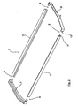
- a bunk 1 which has a frame 2, in which a slatted frame 3 is inserted. Furthermore, a mattress 4 is used in the frame 2. All components are preferably connected to each other positively and / or non-positively.
- the frame 2 of the invention consists of several parts of interconnectable frame parts, namely two to form a rectangular shape of the frame 2 parallel to each other and a predetermined distance having frame longitudinal members 5, 6 and two of the frame longitudinal parts 5, 6 subsequent frame side parts. 7 , 8, which form the front side parts in the present example case.
- the two frame longitudinal parts 5, 6 have an equal length and are produced by injection molding profile parts, preferably made of light metal.
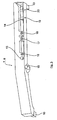
- the two frame side parts 7, 8 are, however, as this particular from Fig. 3 shows, formed as a die-cast parts, which have a number of functional elements described in more detail below in an integral manner.
- the frame side parts 7, 8 are each connected by means of two connectors 9 with the frame members 5, 6. Specifically, this is on the frame side parts 7, 8 each end a plug-in pin 10 is formed in the in Fig. 1 shown mounted state positively engages in a plug-pin receptacle 11 which is formed at the two end portions of the frame longitudinal members 5, 6.
- a screw 12 is shown schematically in the Fig. 1 located.
- the frame side parts 7, 8 which are preferably designed as common parts, functional elements in the die casting process, here, for example, through holes or Anschraubpositionen 13, 14 for the slatted frame 3, a bearing pin 15 for a front bedding storage, connection points 16, 17, 18 for gas springs and screw points 19, 20 of the bunk on a rear couchette.
Landscapes
- Engineering & Computer Science (AREA)
- Transportation (AREA)
- Mechanical Engineering (AREA)
- Chemical & Material Sciences (AREA)
- Combustion & Propulsion (AREA)
- Health & Medical Sciences (AREA)
- Public Health (AREA)
- Seats For Vehicles (AREA)
- Body Structure For Vehicles (AREA)
- Mattresses And Other Support Structures For Chairs And Beds (AREA)
Description
- Die Erfindung betrifft einen Schlafliegen-Rahmen von Fahrerhäusern von Nutzfahrzeugen, insbesondere von Lastkraftwagen, entsprechend den Merkmalen des Anspruchs 1.
- In Fernverkehr-Fahrerhäusern können bis zu zwei Schlafliegen eingebaut werden. Diese Schlafliegen werden in der Regel hinter den Sitzen übereinander angeordnet. Sowohl die untere als auch die obere Schlafliege können hochklappbar ausgeführt sein. Die Schlafliegen bestehen im Regelfall aus einem Tragrahmen bzw. Bettrahmen mit einem Lattenrost als Unterfederung sowie einer auf dem Lattenrost aufliegenden Matratze. Für unterschiedliche Modelle von Fahrzeugen werden regelmäßig auch unterschiedliche Arten bzw. Größen von Schlafliegen benötigt, wobei zudem, im Gegensatz zu herkömmlichen Betten, eine größere Funktionalität bzw. sichere Fixierung der Schlafliege im Fahrerhaus erforderlich ist, was eine Vielzahl weiterer Bauteile bzw. Funktionselemente erforderlich macht, um eine qualitativ hochwertige Schiafliege zur Verfügung zu stellen.
- Für unterschiedliche Fahrerhäuser von Nutzfahrzeugen sind somit regelmäßig eine Vielzahl von unterschiedlichen Schlafliegen vorzuhalten.
- Aus der
DE 10 2004 045 185 B3 ist bereits eine verstellbare Schlafliege für Nutzfahrzeuge bekannt, bei der zwei Segmente einer Liege in unterschiedliche Postionen verstellt bzw. verfahren werden können. Gemäß der dortigen Fig. 5 kann der Schlafliegen-Rahmen mehrteilig ausgebildet sein. Konkret umfasst der Rahmen hier vier Profilleisten, die über Verbindungsstücke als separate Bauteile an ihren Ecken miteinander verbunden sind. In eine Nut eines dem Fahrzeuginnenraum zugewandten Rahmenlängsteils kann ein Funktionselement lösbar eingehängt werden, zum Beispiel ein Cupholder, ein Ablagetisch, eine Leselampe oder eine Absturzsicherung. - Aus der
EP 0 939 023 A2 ist ebenfalls eine Schlafliege in einem Fahrerhaus eines Nutzfahrzeuges bekannt, mittels der der Liegekomfort erhöht und ein Klappergeräusch der Schlafliege im Fahrzeugbetrieb unterbunden werden soll. Hierzu ist vorgesehen, dass die Schlafliege jeweils im Bereich ihrer stirnseitig angeordneten Lagerungen schwingungsmäßig vom Fahrerhaus entkoppelt ist. Für diese schwingungsmäßige Entkopplung werden konkret an den entsprechenden Lagerstellen gummielastische Feder-/Dämpfungselemente vorgesehen. Ein mehrteiliger Rahmenaufbau ist hier nicht vorgesehen. - Die
EP 0 036 758 A1 betrifft ebenfalls eine Schlafliegenanordnung für Fahrerkabinen, bei dem in Verbindung mit einer geeigneten Klappung von Innensitzen ein Bett in seine Liegestellung überführt werden kann. Im aufgeklappten, verstauten Zustand ist das Bett hinter einer Sitzanordnung verstaut. DieUS 3,524,673 betrifft eine Bettanordnung in einer Fahrerkabine, welche Bettanordnung teleskopierbare und faltbare Bauteile aufweist, um ein Bett von seiner Verstaustellung in seine Funktionsstellung zu überführen. - Weiter ist eine klappbare Liege für eine Fahrgastzelle eines Kraftfahrzeugs auch aus der
DE 10 2004 001 431 A1 bekannt. - Auch aus der
WO 2006/131634 A2 ist ein Bettrahmen bekannt, der teleskopierbare Seitenschienen aufweist und zudem schwenkbar im Innenraum eines Fahrzeugs gelagert und angeordnet ist. - Demgegenüber ist es Aufgabe der vorliegenden Erfindung, einen Schlafliegen-Rahmen für Schlafliegen von Fahrerhäusern von Nutzfahrzeugen, insbesondere von Lastkraftwagen, zur Verfügung zu stellen, der auf baulich und fertigungstechnisch einfache Weise herstellbar ist und der auf einfache Weise an unterschiedliche Fahrerhausgegebenheiten von Nutzfahrzeugen anpassbar ist.
- Diese Aufgabe wird gelöst mit den Merkmalen des Anspruchs 1. Vorteilhafte Ausgestaltungen der Erfindung sind Gegenstand der Unteransprüche.
- Gemäß Anspruch 1 ist ein Schlafliegen-Rahmen für Schlafliegen von Fahrerhäusern von Nutzfahrzeugen vorgesehen, der mehrteilig aus einzelnen miteinander verbindbaren Rahmenteilen aufgebaut ist, wobei der Rahmen eine Rechteckform aufweist mit zwei Rahmenlängsteilen sowie daran anschließenden Rahmenseitenteilen als Stirnseitenteilen. Erfindungsgemäß sind in die Rahmenseitenteile Funktionselemente integriert, wobei die die Funktionselemente aufweisenden Rahmenseitenteile im Gussverfahren hergestellte Gussbauteile sind, während die keine integral damit ausgebildeten Funktionselemente aufweisenden Rahmenlängsteile durch Strangpressprofile gebildet sind.
- Der Ausbildung von Rahmenteilen durch Strangpressprofile bzw. durch Gussbauteile liegt die allgemeine Idee zugrunde, dass diejenigen Rahmenteile, die keine integral damit ausbildbaren Funktionselemente aufweisen, in einfacher und preiswerter Weise durch Strangpressen hergestellt werden sollen, während die die Funktionselemente integral aufweisenden Rahmenteile dagegen im demgegenüber etwas aufwändigeren Gussverfahren hergestellt werden sollen, da mittels eines derartigen Gießverfahrens die Funktionsintegration auf einfache und preiswerte Weise möglich ist.
- Weiter ist erfindungsgemäß vorgesehen, dass die Rahmenseitenteile mit den Rahmenlängsteilen mittels einer Steckverbindung verbindbar sind. Mit einer derartigen Steckverbindung lässt sich auf einfache Weise eine funktionssichere Verbindung der unterschiedlichen Rahmenteile herstellen, wobei die Steckverbindung durch einen am Rahmenseitenteil angeformten Steckzapfen ausgebildet, der formschlüssig in eine rahmenlängsteilseitige Steckzapfenaufnahme als weiteren Bestandteil der Steckverbindung eingesteckt werden kann. Zur sicheren Fixierung dieser Steckverbindung kann ferner vorgesehen sein, dass diese mittels einer zusätzlichen Sicherheitseinrichtung, insbesondere mittels einer Sicherungsschraube und/oder mittels eines Sicherungssplintes, fixiert ist. Die Fixierung kann hier z. B. konkret durch eine quer zur Steckrichtung durch den Steckzapfen und die Steckzapfenaufnahme gesteckte Sicherungsschraube oder Sicherungssplint gebildet sein.
- Die Mehrteiligkeit erlaubt ferner eine flexible und wenig bauteilintensive Anpassung eines Rahmens an unterschiedliche Fahrerhausgegebenheiten. So können insbesondere in Verbindung mit der vorgesehenen Integration von Funktionselementen in die Rahmenseitenteile vorteilhaft standardisierte Rahmenteile zur Verfügung gestellt werden, z. B. in Form von Haltern und/oder Aufsteckelementen und/oder Anbindungspunkten und/oder Lagerelementen oder dergleichen, wie sie für nahezu alle Schlafliegenausbildungen erforderlich sind. Dadurch können bestimmte Rahmenteile, insbesondere Rahmenseitenteile eines eine Rechteckform aufweisenden Rahmens, die an Rahmenlängsteile anschließen, zur Verfügung gestellt werden, die in einer Vielzahl von unterschiedlichen Fahrerhäusern verwendet werden können, so dass z. B. zur Längenanpassung lediglich die anderen Rahmenteile, insbesondere die Rahmenlängsteile in unterschiedlicher Größe vorgehalten werden müssen. Grundsätzlich können jedoch auch Funktionselemente aufweisende Rahmenseitenteile unterschiedlicher Art vorgehalten werden, in denen z. B. unterschiedliche der zuvor genannten Funktionselemente integriert sind, um ein Set von beliebig miteinander kombinierbaren Rahmenteilen auszubilden, so dass eine einfache und individuelle Anpassung an die jeweiligen Fahrerhausgegebenheiten auf einfache Weise möglich ist.
- Gemäß einer besonders bevorzugten Ausgestaltung der Erfindung sind die keine Funktionselemente aufweisenden Rahmenlängsteile durch herstellungstechnisch einfache und preiswerte Leichtmetall-Strangpressprofile gebildet. Grundsätzlich bestünde aber auch die Möglichkeit, anstelle von Leichtmetall ein Kunststoffmaterial vorzusehen.
- Gemäß einer weiteren besonders bevorzugten Ausgestaltung der vorliegenden Erfindung ist ferner vorgesehen, dass die die Funktionselemente aufweisenden Rahmenseitenteile als Druckgussbauteile ausgebildet sind. Bevorzugtes Material ist hier ebenfalls wiederum ein Leichtmetall. Grundsätzlich ist auch die Verwendung von Kunststoff möglich.
- Weiter ist erfindungsgemäß zur Ausbildung der Schlafliege vorgesehen, den Rahmen form- und/oder kraftschlüssig mit einem Lattenrost zu verbinden. Auf dem Lattenrost kann wiederum eine Matratze aufgelegt sein. Diese Matratze kann dann wieder form- und/oder kraftschlüssig mit dem Rahmen und/oder dem Lattenrost verbunden sein.
- Die Erfindung wird nachfolgend anhand einer Zeichnung näher erläutert.
- Es zeigen:
- Fig. 1
- schematisch eine perspektivische Draufsicht auf eine Schlafliege mit erfindungsgemäßem Rahmen,
- Fig. 2
- schematisch eine auseinandergezogene, perspektivische Darstellung des erfindungsgemäßen Rahmens, und
- Fig. 3
- eine vergrößerte Detailansicht des Funktionselemente aufweisenden Rahmenseitenteils.
- In der
Fig. 1 ist schematisch und perspektivisch eine Schlafliege 1 gezeigt, die einen Rahmen 2 aufweist, in den ein Lattenrost 3 eingesetzt ist. Ferner ist im Rahmen 2 eine Matratze 4 eingesetzt. Sämtliche Bauteile sind bevorzugt miteinander form- und/oder kraftschlüssig verbunden. - Wie dies insbesondere der
Fig. 2 entnommen werden kann, besteht der erfindungsgemäße Rahmen 2 mehrteilig aus einzelnen miteinander verbindbaren Rahmenteilen, nämlich zwei zur Ausbildung einer Rechteckform des Rahmens 2 parallel zueinander verlaufenden und voneinander einen vorgegebenen Abstand aufweisenden Rahmenlängsteilen 5, 6 sowie aus zwei an die Rahmenlängsteile 5, 6 anschließenden Rahmenseitenteilen 7, 8, die im vorliegenden Beispielfall die Stirnseitenteile ausbilden. - Die beiden Rahmenlängsteile 5, 6 weisen eine gleiche Länge auf und sind im Spritzgussverfahren hergestellte Profilteile, vorzugsweise aus Leichtmetall.
- Die beiden Rahmenseitenteile 7, 8 sind dagegen, wie dies insbesondere aus der
Fig. 3 hervorgeht, als Druckgussteile ausgebildet, die eine Reihe von nachfolgend noch näher beschriebenen Funktionselementen in integraler Weise aufweisen. Die Rahmenseitenteile 7, 8 sind jeweils mittels zweier Steckverbindungen 9 mit den Rahmenlängsteilen 5, 6 verbunden. Konkret ist hierzu an den Rahmenseitenteilen 7, 8 jeweils endseitig ein Steckzapfen 10 angeformt, der im in derFig. 1 dargestellten montierten Zustand formschlüssig in eine Steckzapfenaufnahme 11 eingreift, die an den beiden Endbereichen der Rahmenlängsteile 5, 6 ausgebildet ist. - Zur Fixierung der Steckverbindung 9 kann zudem vorgesehen sein, diese mittels einer zusätzlichen Schraubverbindung zu sichern. Eine derartige Schraubverbindung 12 ist schematisch in der
Fig. 1 eingezeichnet. - Wie dies insbesondere der
Fig. 3 entnommen werden kann, sind an den Rahmenseitenteilen 7, 8, die bevorzugt als Gleichteile ausgebildet sind, Funktionselemente integral im Druckgussverfahren mitangeformt, hier beispielsweise Durchgangslöcher bzw. Anschraubpositionen 13, 14 für den Lattenrost 3, ein Lagerbolzen 15 für eine vordere Liegenlagerung, Anbindungspunkte 16, 17, 18 für Gasfedern sowie Anschraubpunkte 19, 20 der Schlafliege an einem hinteren Liegenlager.
Claims (4)
- Schlafliegen-Rahmen für Schlafliegen von Fahrerhäusern von Nutzfahrzeugen, insbesondere Lastkraftwagen, wobei der Rahmen (2) mehrteilig aus einzelnen miteinander verbindbaren Rahmenteilen (5, 6, 7, 8) aufgebaut ist, wobei der Rahmen (2) eine Rechteckform aufweist mit zwei Rahmenlängsteilen (5, 6) sowie daran anschließenden Rahmenseitenteilen (7, 8) als Stirnseitenteile, wobei die Rahmenseitenteile (7, 8) mit den Rahmenlängsteilen (5, 6) mittels einer Steckverbindung (9) verbindbar sind, und wobei in die Rahmenseitenteiie (7, 8) Funktionselemente (10, 13 bis 20) integriert sind, und die die Funktionselemente (10, 13 bis 20) aufweisenden Rahmenseitenteile (7, 8) im Gussverfahren hergestellte Gussbauteile sind,
und wobei die Rahmenlängsteile (5, 6) durch Strangpressprofile gebildet sind,
und wobei die Steckverbindung (9) jeweils einen am Rahmenseitenteil (7,8) angeformten Steckzapfen (10) aufweist, der im montierten Zustand formschlüssig in eine rahmenlängsteilseitige Steckzapfenaufnahme (11) eingesteckt ist,
und wobei der Rahmen (2) zur Ausbildung einer Schlafliege (1) form- und/oder kraftschlüssig mit einem Lattenrost (3) verbunden ist. - Rahmen nach Anspruch 1, dadurch gekennzeichnet, dass als Funktionselemente (13 bis 20) Halter- und/oder Aufsteckelemente und/oder Anbindungspunkte, und/oder Lagerelemente, und/oder Schraublöcher (13, 14) zur Lattenrostfixierung und/oder Lagerbolzen (15) für eine Liegenlagerung und/oder Anbindungselemente (16, 17, 18) für Gasfedern und/oder Anschraubpunkte (19, 20) für eine Liegenlagerung, vorgesehen sind.
- Rahmen nach Anspruch 1 oder Anspruch 2, dadurch gekennzeichnet, dass die Steckverbindung (9) mittels wenigstens einer Sicherheitseinrichtung (12), insbesondere mittels einer Sicherungsschraube und/oder mittels eines Sicherungssplintes, fixierbar ist.
- Rahmen nach Anspruch 1, dadurch gekennzeichnet, dass auf den Lattenrost (3) wiederum eine Matratze (4) aufgelegt ist, die vorzugsweise form- und/oder kraftschlüssig mit dem Rahmen (2) und/oder dem Lattenrost (3) verbunden ist.
Priority Applications (1)
| Application Number | Priority Date | Filing Date | Title |
|---|---|---|---|
| PL08012433T PL2022708T3 (pl) | 2007-08-08 | 2008-07-10 | Rama leżanki do spania dla leżanek do spania w kabinach kierowcy pojazdów użytkowych |
Applications Claiming Priority (1)
| Application Number | Priority Date | Filing Date | Title |
|---|---|---|---|
| DE102007037456A DE102007037456A1 (de) | 2007-08-08 | 2007-08-08 | Schlafliegen-Rahmen für Schlafliegen von Fahrerhäusern von Nutzfahrzeugen |
Publications (3)
| Publication Number | Publication Date |
|---|---|
| EP2022708A2 EP2022708A2 (de) | 2009-02-11 |
| EP2022708A3 EP2022708A3 (de) | 2009-06-24 |
| EP2022708B1 true EP2022708B1 (de) | 2013-09-11 |
Family
ID=39892229
Family Applications (1)
| Application Number | Title | Priority Date | Filing Date |
|---|---|---|---|
| EP08012433.2A Active EP2022708B1 (de) | 2007-08-08 | 2008-07-10 | Schlafliegen-Rahmen für Schlafliegen von Fahrerhäusern von Nutzfahrzeugen |
Country Status (3)
| Country | Link |
|---|---|
| EP (1) | EP2022708B1 (de) |
| DE (1) | DE102007037456A1 (de) |
| PL (1) | PL2022708T3 (de) |
Families Citing this family (1)
| Publication number | Priority date | Publication date | Assignee | Title |
|---|---|---|---|---|
| JP6410615B2 (ja) * | 2015-01-09 | 2018-10-24 | 本田技研工業株式会社 | 収納ベッド付き車両 |
Family Cites Families (6)
| Publication number | Priority date | Publication date | Assignee | Title |
|---|---|---|---|---|
| US3524673A (en) | 1968-04-08 | 1970-08-18 | Western Sales & Supply Co | Bed for truck cabs |
| EP0036758A1 (de) | 1980-03-21 | 1981-09-30 | Motor Panels (Coventry) Limited | Schlafeinrichtung für Fahrerhäuser |
| DE19808449A1 (de) | 1998-02-27 | 1999-09-09 | Man Nutzfahrzeuge Ag | Schlafliege in Nutzfahrzeug-Fahrerhäusern |
| DE102004001431A1 (de) | 2004-01-09 | 2005-08-11 | Daimlerchrysler Ag | Klappbare Liege für eine Fahrgastzelle eines Kraftfahrzeugs |
| DE102004045185B3 (de) | 2004-09-17 | 2005-11-10 | Isringhausen Gmbh & Co. Kg | Verstellbare Liege |
| FR2886900B1 (fr) | 2005-06-08 | 2007-09-21 | Richard Maximilien | Cadre de lit, lit comportant un tel cadre et procede pour munir d'un tel lit une voiture automobile |
-
2007
- 2007-08-08 DE DE102007037456A patent/DE102007037456A1/de not_active Ceased
-
2008
- 2008-07-10 PL PL08012433T patent/PL2022708T3/pl unknown
- 2008-07-10 EP EP08012433.2A patent/EP2022708B1/de active Active
Also Published As
| Publication number | Publication date |
|---|---|
| PL2022708T3 (pl) | 2014-02-28 |
| EP2022708A2 (de) | 2009-02-11 |
| DE102007037456A1 (de) | 2009-02-12 |
| EP2022708A3 (de) | 2009-06-24 |
Similar Documents
| Publication | Publication Date | Title |
|---|---|---|
| DE102004063094B4 (de) | Passagiersitzeinheit, insbesondere für Verkehrsflugzeuge | |
| EP0861165B1 (de) | Klappsitzbank | |
| EP1502810A2 (de) | Sitzanordnung für Fahrzeuge | |
| DE102018210033A1 (de) | Baugruppe mit einer mit einer Bodenbaugruppe verbundenen Führungsschiene | |
| EP1867522A2 (de) | Einbauschlafmöbel zum Einbau in Kastenwagen, Wohnmobilen und dergleichen | |
| DE102014207288A1 (de) | Sitzanlage für ein kraftfahrzeug | |
| DE102015216171A1 (de) | Sitzbefestigungssystem für ein Fahrzeug | |
| DE102005039235A1 (de) | Wohnmobil | |
| DE102009052581A1 (de) | Fahrzeugsitz, insbesondere Kraftfahrzeugsitz | |
| DE102021115128B4 (de) | Fahrzeug mit umgebautem Innenraum | |
| DE202011003731U1 (de) | Wohnmobil mit Sitzgruppe, Schlafgelegenheit und Garage im Fahrzeugheck | |
| DE202013008497U1 (de) | Anordnung einer variablen Sitzgruppe mit Tisch über einem fest installierten Bett oder fest installierten Betten insbesondere in den Anwendungsgebieten Wohnwagen, Wohnmobil, Wohnmobil-Kastenwagen und Absetzkabine | |
| EP2022708B1 (de) | Schlafliegen-Rahmen für Schlafliegen von Fahrerhäusern von Nutzfahrzeugen | |
| DE10305681A1 (de) | Tischmodul für ein Fahrzeug, insbesondere für ein Kraftfahrzeug | |
| DE10141901C1 (de) | Fahrerhaus eines Nutzfahrzeugs | |
| DE19708044C1 (de) | Befestigungsvorrichtung an einem Kindersitz und an einer hinteren Kraftfahrzeugsitzbank mit umklappbarer Lehne | |
| DE19820880C1 (de) | Fahrzeugsitz | |
| EP3950419B1 (de) | Fahrzeugsitz | |
| DE102008027791A1 (de) | Klapptischanordnung | |
| EP3476650B1 (de) | Sitzgestell eines fahrzeugsitzes | |
| DE9112088U1 (de) | Klappsitzbank | |
| EP1053122A1 (de) | Fahrgastsitz | |
| EP1602529B1 (de) | Wohnmobil mit Alkoven- oder Hubbett | |
| DE102008053961A1 (de) | Fahrzeugsitz für einen Kraftwagen und Fahrerhaus mit einem Fahrzeugsitz | |
| DE202020106212U1 (de) | Ablageboard für ein Wohnmobil, einen Wohnwagen und / oder einen Camper-Van |
Legal Events
| Date | Code | Title | Description |
|---|---|---|---|
| PUAI | Public reference made under article 153(3) epc to a published international application that has entered the european phase |
Free format text: ORIGINAL CODE: 0009012 |
|
| AK | Designated contracting states |
Kind code of ref document: A2 Designated state(s): AT BE BG CH CY CZ DE DK EE ES FI FR GB GR HR HU IE IS IT LI LT LU LV MC MT NL NO PL PT RO SE SI SK TR |
|
| AX | Request for extension of the european patent |
Extension state: AL BA MK RS |
|
| PUAL | Search report despatched |
Free format text: ORIGINAL CODE: 0009013 |
|
| AK | Designated contracting states |
Kind code of ref document: A3 Designated state(s): AT BE BG CH CY CZ DE DK EE ES FI FR GB GR HR HU IE IS IT LI LT LU LV MC MT NL NO PL PT RO SE SI SK TR |
|
| AX | Request for extension of the european patent |
Extension state: AL BA MK RS |
|
| RIC1 | Information provided on ipc code assigned before grant |
Ipc: B60P 3/38 20060101ALI20090518BHEP Ipc: B60P 3/32 20060101ALI20090518BHEP Ipc: B62D 33/06 20060101AFI20081107BHEP |
|
| 17P | Request for examination filed |
Effective date: 20090709 |
|
| 17Q | First examination report despatched |
Effective date: 20090806 |
|
| AKX | Designation fees paid |
Designated state(s): AT BE BG CH CY CZ DE DK EE ES FI FR GB GR HR HU IE IS IT LI LT LU LV MC MT NL NO PL PT RO SE SI SK TR |
|
| RAP1 | Party data changed (applicant data changed or rights of an application transferred) |
Owner name: MAN TRUCK & BUS AG |
|
| GRAP | Despatch of communication of intention to grant a patent |
Free format text: ORIGINAL CODE: EPIDOSNIGR1 |
|
| INTG | Intention to grant announced |
Effective date: 20130424 |
|
| GRAS | Grant fee paid |
Free format text: ORIGINAL CODE: EPIDOSNIGR3 |
|
| GRAA | (expected) grant |
Free format text: ORIGINAL CODE: 0009210 |
|
| AK | Designated contracting states |
Kind code of ref document: B1 Designated state(s): AT BE BG CH CY CZ DE DK EE ES FI FR GB GR HR HU IE IS IT LI LT LU LV MC MT NL NO PL PT RO SE SI SK TR |
|
| REG | Reference to a national code |
Ref country code: GB Ref legal event code: FG4D Free format text: NOT ENGLISH |
|
| REG | Reference to a national code |
Ref country code: CH Ref legal event code: EP |
|
| REG | Reference to a national code |
Ref country code: AT Ref legal event code: REF Ref document number: 631465 Country of ref document: AT Kind code of ref document: T Effective date: 20130915 |
|
| REG | Reference to a national code |
Ref country code: IE Ref legal event code: FG4D Free format text: LANGUAGE OF EP DOCUMENT: GERMAN |
|
| REG | Reference to a national code |
Ref country code: DE Ref legal event code: R096 Ref document number: 502008010627 Country of ref document: DE Effective date: 20131107 |
|
| REG | Reference to a national code |
Ref country code: NL Ref legal event code: T3 |
|
| REG | Reference to a national code |
Ref country code: SE Ref legal event code: TRGR |
|
| PG25 | Lapsed in a contracting state [announced via postgrant information from national office to epo] |
Ref country code: CY Free format text: LAPSE BECAUSE OF FAILURE TO SUBMIT A TRANSLATION OF THE DESCRIPTION OR TO PAY THE FEE WITHIN THE PRESCRIBED TIME-LIMIT Effective date: 20130724 Ref country code: LT Free format text: LAPSE BECAUSE OF FAILURE TO SUBMIT A TRANSLATION OF THE DESCRIPTION OR TO PAY THE FEE WITHIN THE PRESCRIBED TIME-LIMIT Effective date: 20130911 Ref country code: HR Free format text: LAPSE BECAUSE OF FAILURE TO SUBMIT A TRANSLATION OF THE DESCRIPTION OR TO PAY THE FEE WITHIN THE PRESCRIBED TIME-LIMIT Effective date: 20130911 Ref country code: NO Free format text: LAPSE BECAUSE OF FAILURE TO SUBMIT A TRANSLATION OF THE DESCRIPTION OR TO PAY THE FEE WITHIN THE PRESCRIBED TIME-LIMIT Effective date: 20131211 |
|
| REG | Reference to a national code |
Ref country code: LT Ref legal event code: MG4D |
|
| PG25 | Lapsed in a contracting state [announced via postgrant information from national office to epo] |
Ref country code: LV Free format text: LAPSE BECAUSE OF FAILURE TO SUBMIT A TRANSLATION OF THE DESCRIPTION OR TO PAY THE FEE WITHIN THE PRESCRIBED TIME-LIMIT Effective date: 20130911 Ref country code: SI Free format text: LAPSE BECAUSE OF FAILURE TO SUBMIT A TRANSLATION OF THE DESCRIPTION OR TO PAY THE FEE WITHIN THE PRESCRIBED TIME-LIMIT Effective date: 20130911 Ref country code: GR Free format text: LAPSE BECAUSE OF FAILURE TO SUBMIT A TRANSLATION OF THE DESCRIPTION OR TO PAY THE FEE WITHIN THE PRESCRIBED TIME-LIMIT Effective date: 20131212 Ref country code: FI Free format text: LAPSE BECAUSE OF FAILURE TO SUBMIT A TRANSLATION OF THE DESCRIPTION OR TO PAY THE FEE WITHIN THE PRESCRIBED TIME-LIMIT Effective date: 20130911 |
|
| REG | Reference to a national code |
Ref country code: PL Ref legal event code: T3 |
|
| PG25 | Lapsed in a contracting state [announced via postgrant information from national office to epo] |
Ref country code: CY Free format text: LAPSE BECAUSE OF FAILURE TO SUBMIT A TRANSLATION OF THE DESCRIPTION OR TO PAY THE FEE WITHIN THE PRESCRIBED TIME-LIMIT Effective date: 20130911 |
|
| PG25 | Lapsed in a contracting state [announced via postgrant information from national office to epo] |
Ref country code: RO Free format text: LAPSE BECAUSE OF FAILURE TO SUBMIT A TRANSLATION OF THE DESCRIPTION OR TO PAY THE FEE WITHIN THE PRESCRIBED TIME-LIMIT Effective date: 20130911 Ref country code: CZ Free format text: LAPSE BECAUSE OF FAILURE TO SUBMIT A TRANSLATION OF THE DESCRIPTION OR TO PAY THE FEE WITHIN THE PRESCRIBED TIME-LIMIT Effective date: 20130911 Ref country code: EE Free format text: LAPSE BECAUSE OF FAILURE TO SUBMIT A TRANSLATION OF THE DESCRIPTION OR TO PAY THE FEE WITHIN THE PRESCRIBED TIME-LIMIT Effective date: 20130911 Ref country code: SK Free format text: LAPSE BECAUSE OF FAILURE TO SUBMIT A TRANSLATION OF THE DESCRIPTION OR TO PAY THE FEE WITHIN THE PRESCRIBED TIME-LIMIT Effective date: 20130911 Ref country code: IS Free format text: LAPSE BECAUSE OF FAILURE TO SUBMIT A TRANSLATION OF THE DESCRIPTION OR TO PAY THE FEE WITHIN THE PRESCRIBED TIME-LIMIT Effective date: 20140111 |
|
| PG25 | Lapsed in a contracting state [announced via postgrant information from national office to epo] |
Ref country code: ES Free format text: LAPSE BECAUSE OF FAILURE TO SUBMIT A TRANSLATION OF THE DESCRIPTION OR TO PAY THE FEE WITHIN THE PRESCRIBED TIME-LIMIT Effective date: 20130911 |
|
| REG | Reference to a national code |
Ref country code: DE Ref legal event code: R097 Ref document number: 502008010627 Country of ref document: DE |
|
| PG25 | Lapsed in a contracting state [announced via postgrant information from national office to epo] |
Ref country code: PT Free format text: LAPSE BECAUSE OF FAILURE TO SUBMIT A TRANSLATION OF THE DESCRIPTION OR TO PAY THE FEE WITHIN THE PRESCRIBED TIME-LIMIT Effective date: 20140113 |
|
| PLBE | No opposition filed within time limit |
Free format text: ORIGINAL CODE: 0009261 |
|
| STAA | Information on the status of an ep patent application or granted ep patent |
Free format text: STATUS: NO OPPOSITION FILED WITHIN TIME LIMIT |
|
| 26N | No opposition filed |
Effective date: 20140612 |
|
| REG | Reference to a national code |
Ref country code: DE Ref legal event code: R097 Ref document number: 502008010627 Country of ref document: DE Effective date: 20140612 |
|
| PG25 | Lapsed in a contracting state [announced via postgrant information from national office to epo] |
Ref country code: DK Free format text: LAPSE BECAUSE OF FAILURE TO SUBMIT A TRANSLATION OF THE DESCRIPTION OR TO PAY THE FEE WITHIN THE PRESCRIBED TIME-LIMIT Effective date: 20130911 |
|
| PG25 | Lapsed in a contracting state [announced via postgrant information from national office to epo] |
Ref country code: LU Free format text: LAPSE BECAUSE OF FAILURE TO SUBMIT A TRANSLATION OF THE DESCRIPTION OR TO PAY THE FEE WITHIN THE PRESCRIBED TIME-LIMIT Effective date: 20140710 |
|
| REG | Reference to a national code |
Ref country code: CH Ref legal event code: PL |
|
| GBPC | Gb: european patent ceased through non-payment of renewal fee |
Effective date: 20140710 |
|
| REG | Reference to a national code |
Ref country code: IE Ref legal event code: MM4A |
|
| PG25 | Lapsed in a contracting state [announced via postgrant information from national office to epo] |
Ref country code: LI Free format text: LAPSE BECAUSE OF NON-PAYMENT OF DUE FEES Effective date: 20140731 Ref country code: CH Free format text: LAPSE BECAUSE OF NON-PAYMENT OF DUE FEES Effective date: 20140731 |
|
| PG25 | Lapsed in a contracting state [announced via postgrant information from national office to epo] |
Ref country code: GB Free format text: LAPSE BECAUSE OF NON-PAYMENT OF DUE FEES Effective date: 20140710 |
|
| PG25 | Lapsed in a contracting state [announced via postgrant information from national office to epo] |
Ref country code: IE Free format text: LAPSE BECAUSE OF NON-PAYMENT OF DUE FEES Effective date: 20140710 |
|
| PG25 | Lapsed in a contracting state [announced via postgrant information from national office to epo] |
Ref country code: MC Free format text: LAPSE BECAUSE OF FAILURE TO SUBMIT A TRANSLATION OF THE DESCRIPTION OR TO PAY THE FEE WITHIN THE PRESCRIBED TIME-LIMIT Effective date: 20130911 |
|
| PG25 | Lapsed in a contracting state [announced via postgrant information from national office to epo] |
Ref country code: BG Free format text: LAPSE BECAUSE OF FAILURE TO SUBMIT A TRANSLATION OF THE DESCRIPTION OR TO PAY THE FEE WITHIN THE PRESCRIBED TIME-LIMIT Effective date: 20130911 |
|
| PG25 | Lapsed in a contracting state [announced via postgrant information from national office to epo] |
Ref country code: MT Free format text: LAPSE BECAUSE OF FAILURE TO SUBMIT A TRANSLATION OF THE DESCRIPTION OR TO PAY THE FEE WITHIN THE PRESCRIBED TIME-LIMIT Effective date: 20130911 |
|
| REG | Reference to a national code |
Ref country code: FR Ref legal event code: PLFP Year of fee payment: 9 |
|
| PG25 | Lapsed in a contracting state [announced via postgrant information from national office to epo] |
Ref country code: BE Free format text: LAPSE BECAUSE OF FAILURE TO SUBMIT A TRANSLATION OF THE DESCRIPTION OR TO PAY THE FEE WITHIN THE PRESCRIBED TIME-LIMIT Effective date: 20140731 Ref country code: TR Free format text: LAPSE BECAUSE OF FAILURE TO SUBMIT A TRANSLATION OF THE DESCRIPTION OR TO PAY THE FEE WITHIN THE PRESCRIBED TIME-LIMIT Effective date: 20130911 Ref country code: HU Free format text: LAPSE BECAUSE OF FAILURE TO SUBMIT A TRANSLATION OF THE DESCRIPTION OR TO PAY THE FEE WITHIN THE PRESCRIBED TIME-LIMIT; INVALID AB INITIO Effective date: 20080710 |
|
| REG | Reference to a national code |
Ref country code: FR Ref legal event code: PLFP Year of fee payment: 10 |
|
| REG | Reference to a national code |
Ref country code: FR Ref legal event code: PLFP Year of fee payment: 11 |
|
| REG | Reference to a national code |
Ref country code: DE Ref legal event code: R081 Ref document number: 502008010627 Country of ref document: DE Owner name: MAN TRUCK & BUS SE, DE Free format text: FORMER OWNER: MAN TRUCK & BUS AG, 80995 MUENCHEN, DE |
|
| PGFP | Annual fee paid to national office [announced via postgrant information from national office to epo] |
Ref country code: NL Payment date: 20250724 Year of fee payment: 18 |
|
| PGFP | Annual fee paid to national office [announced via postgrant information from national office to epo] |
Ref country code: DE Payment date: 20250728 Year of fee payment: 18 |
|
| PGFP | Annual fee paid to national office [announced via postgrant information from national office to epo] |
Ref country code: PL Payment date: 20250703 Year of fee payment: 18 Ref country code: IT Payment date: 20250721 Year of fee payment: 18 |
|
| PGFP | Annual fee paid to national office [announced via postgrant information from national office to epo] |
Ref country code: FR Payment date: 20250725 Year of fee payment: 18 Ref country code: AT Payment date: 20250718 Year of fee payment: 18 |
|
| PGFP | Annual fee paid to national office [announced via postgrant information from national office to epo] |
Ref country code: SE Payment date: 20250725 Year of fee payment: 18 |