EP0036758A1 - Sleeping arrangement for drivers' cabs - Google Patents
Sleeping arrangement for drivers' cabs Download PDFInfo
- Publication number
- EP0036758A1 EP0036758A1 EP81301168A EP81301168A EP0036758A1 EP 0036758 A1 EP0036758 A1 EP 0036758A1 EP 81301168 A EP81301168 A EP 81301168A EP 81301168 A EP81301168 A EP 81301168A EP 0036758 A1 EP0036758 A1 EP 0036758A1
- Authority
- EP
- European Patent Office
- Prior art keywords
- cab
- bed portion
- seat
- back rest
- secured
- Prior art date
- Legal status (The legal status is an assumption and is not a legal conclusion. Google has not performed a legal analysis and makes no representation as to the accuracy of the status listed.)
- Ceased
Links
- 239000000463 material Substances 0.000 claims description 28
- 230000015572 biosynthetic process Effects 0.000 claims description 3
- 230000001419 dependent effect Effects 0.000 claims 1
- 230000004308 accommodation Effects 0.000 abstract description 2
- 238000010276 construction Methods 0.000 description 4
- 230000004438 eyesight Effects 0.000 description 2
- 230000000717 retained effect Effects 0.000 description 2
- 238000003466 welding Methods 0.000 description 2
- 101001061807 Homo sapiens Rab-like protein 6 Proteins 0.000 description 1
- 102100029618 Rab-like protein 6 Human genes 0.000 description 1
- 239000000853 adhesive Substances 0.000 description 1
- 230000001070 adhesive effect Effects 0.000 description 1
- 239000003000 extruded plastic Substances 0.000 description 1
- 230000013011 mating Effects 0.000 description 1
- 239000002184 metal Substances 0.000 description 1
- 239000002991 molded plastic Substances 0.000 description 1
- 239000002984 plastic foam Substances 0.000 description 1
- 230000029058 respiratory gaseous exchange Effects 0.000 description 1
- 230000000452 restraining effect Effects 0.000 description 1
Images


Classifications
-
- B—PERFORMING OPERATIONS; TRANSPORTING
- B62—LAND VEHICLES FOR TRAVELLING OTHERWISE THAN ON RAILS
- B62D—MOTOR VEHICLES; TRAILERS
- B62D33/00—Superstructures for load-carrying vehicles
- B62D33/06—Drivers' cabs
- B62D33/0612—Cabins with living accommodation, especially for long distance road vehicles, i.e. sleeping, cooking, or other facilities
-
- B—PERFORMING OPERATIONS; TRANSPORTING
- B60—VEHICLES IN GENERAL
- B60N—SEATS SPECIALLY ADAPTED FOR VEHICLES; VEHICLE PASSENGER ACCOMMODATION NOT OTHERWISE PROVIDED FOR
- B60N2/00—Seats specially adapted for vehicles; Arrangement or mounting of seats in vehicles
- B60N2/24—Seats specially adapted for vehicles; Arrangement or mounting of seats in vehicles for particular purposes or particular vehicles
- B60N2/32—Seats specially adapted for vehicles; Arrangement or mounting of seats in vehicles for particular purposes or particular vehicles convertible for other use
- B60N2/34—Seats specially adapted for vehicles; Arrangement or mounting of seats in vehicles for particular purposes or particular vehicles convertible for other use into a bed
-
- F—MECHANICAL ENGINEERING; LIGHTING; HEATING; WEAPONS; BLASTING
- F16—ENGINEERING ELEMENTS AND UNITS; GENERAL MEASURES FOR PRODUCING AND MAINTAINING EFFECTIVE FUNCTIONING OF MACHINES OR INSTALLATIONS; THERMAL INSULATION IN GENERAL
- F16B—DEVICES FOR FASTENING OR SECURING CONSTRUCTIONAL ELEMENTS OR MACHINE PARTS TOGETHER, e.g. NAILS, BOLTS, CIRCLIPS, CLAMPS, CLIPS OR WEDGES; JOINTS OR JOINTING
- F16B5/00—Joining sheets or plates, e.g. panels, to one another or to strips or bars parallel to them
- F16B5/06—Joining sheets or plates, e.g. panels, to one another or to strips or bars parallel to them by means of clamps or clips
- F16B5/0692—Joining sheets or plates, e.g. panels, to one another or to strips or bars parallel to them by means of clamps or clips joining flexible sheets to other sheets or plates or to strips or bars
-
- F—MECHANICAL ENGINEERING; LIGHTING; HEATING; WEAPONS; BLASTING
- F16—ENGINEERING ELEMENTS AND UNITS; GENERAL MEASURES FOR PRODUCING AND MAINTAINING EFFECTIVE FUNCTIONING OF MACHINES OR INSTALLATIONS; THERMAL INSULATION IN GENERAL
- F16B—DEVICES FOR FASTENING OR SECURING CONSTRUCTIONAL ELEMENTS OR MACHINE PARTS TOGETHER, e.g. NAILS, BOLTS, CIRCLIPS, CLAMPS, CLIPS OR WEDGES; JOINTS OR JOINTING
- F16B5/00—Joining sheets or plates, e.g. panels, to one another or to strips or bars parallel to them
- F16B5/06—Joining sheets or plates, e.g. panels, to one another or to strips or bars parallel to them by means of clamps or clips
- F16B5/0607—Joining sheets or plates, e.g. panels, to one another or to strips or bars parallel to them by means of clamps or clips joining sheets or plates to each other
- F16B5/0621—Joining sheets or plates, e.g. panels, to one another or to strips or bars parallel to them by means of clamps or clips joining sheets or plates to each other in parallel relationship
- F16B5/0635—Joining sheets or plates, e.g. panels, to one another or to strips or bars parallel to them by means of clamps or clips joining sheets or plates to each other in parallel relationship fastened over the edges of the sheets or plates
Definitions
- This invention relates to vehicle cabs, more parf( icularly cabs in which sleeping accommodation is provided.
- the present invention consists in a vehicle cab having first and second seats spaced laterally in the cab sustantially in alignment with one another and each seat having a back rest, characterised in that the back rest of each seat carries, or is adapted to carry, on its back a bed portion and each back rest is hinged relative to a seat portion of the seat so as to be pivotable forwardly towards the seat portion into a lowered position whereby the bed portion can take up a substantially horizontal position, a further bed portion is provided which is dimensioned and shaped so as to fit between the bed portions on the back rests, support means support the further bed portion between the seats whereby the three bed portions may be arranged substantially horizontally and substantially in alignment to constitute a bunk, and means are provided for storing the further bed portion in the cab when not required for formation of the bunk.
- the bed portion associated with each seat may be detachably mounted on the back rest, being removable when not required for use, but preferably the bed portion is secured to, or integral with, the back rest for ease of assembly of the bunk.
- One of the seats may be in a fixed position and the support means may be arranged so as to support the further bed portion in alignment with the bed portion secured to the back rest of that seat when in the forwardly pivoted position.
- the support means may be in a fixed position in the cab or may be adjustable and/or removable.
- the further bed portion may be hinged along one side to a mounting in the cab at or towards the rear thereof so that it may be pivoted forwardly and downwardly from a vertical stored position for formation of the bunk bed.
- the bed portions may be cushioned.
- a cushioned back rest bed portion may be stepped or formed so as to provide a pillow.
- each seat and the further bed portion may each have first and second elements secured to it arranged so that they are vertically spaced when the back rest is erect. These elements constitute panel support members.
- On each seat a panel of material is connected between the first and second elements of the back rest and a further panel of material is connected between the first and second elements of the further bed portion. The material of the panel may be connected under tension to the first and second elements.
- Means may be provided releasably to connect a side edge of the panel of at least one seat to the adjacent side edge of the further panel.
- Preferably means are provided releasably to connect the side edges of the further panel to the respective adjacent side edges of the panel of each seat.
- the back rest of either or both seats may have a third element which provides an anchorage to which the side edge of the panel remote from the further mattress portion may be connected.
- material as used herein is intended to include a sheet or net of material or webbing.
- the properties required of the material are that it will support the human body without excessive sag.
- the material will preferably allow "breathing” so as to avoid undue perspiration of the user.
- the material when in sheet form, may have perforations.
- suitable materials include canvas, woven man made fibres and formed moulded or extruded plastics materials.
- the mattress or base of the bed is formed by the panels of material instead of by cushioned members, an uncush- ioned yet pliant support is provided for the user.
- the user of the bed will normally have some form of bedding which may conveniently be a sleeping bag.
- the latter may be additionally filled or padded at its under surface to compensate for the lack of cushioning on the panels.
- the material panels may form a support on to which a mattress is placed rather than being used as a mattress itself.
- the cab may be provided with a second bunk stowed in a vertical, or substantially vertical, position extending across the back of the cab behind the further bed portion and arranged so that, with the further bed portion in the horizontal position, the second bunk may be erected, preferably above and spaced vertically from the first bunk.
- a driver's seat 1 which, in known manner (not shown), may be raised and lowered about a mean position and which may be adjusted forwards or backwards from a mean position to suit the driver.
- the range of vertical movement is generally of the order of 5 cm. up and down from the mean position.
- a passenger seat 2 is provided on a seat box (not shown) at the other side of the cab and the position of this is fixed.
- Each seat has a seat portion 3 and a back rest 4 which is hinged at 5 to the seat portion.
- a bed portion 6 is secured to the back of each back rest 4.
- the bed portion When the back rest is pivoted forwardly and downwardly to the position shown at 4a in Figure 1 the bed portion takes up the position shown at 6a and is locked in that position, for example by means of a conventional spring loaded pawl and notch mechanism between the back rest and hinge structure or by a restraining strap, to prevent rocking of the bed portion when in use.
- a support which may conveniently be a locker 7, is hinged to the floor of the cab at 8 and may be rotated about the hinge to a forward position shown in broken lines at 7a in Figures 1 and 3.
- a further bed portion 9 of generally rectangular shape is hinged to the cab rear panel 11 at 12 and is retained in a vertical stored position by straps 13 releasably secured between the panel 11 and bed portion 9.
- bed portion 9 is pivoted forwardly and downwardly to the position shown at 9a in which its upper surface is aligned with the upper surfaces of bed portions 6 in their positions 6a, the driver's seat 1 being assumed to be in alignment with the passenger seat, for example at the mean position of adjustment of the driver's seat.
- the three bed portions 6 and 9 together form a bunk.
- the bed portion 9 since the bed portion 9 is in a central position when stowed at the back of the cab it will not obscure vision out of rear side windows of the cab nor will it obscure vision through side windows, if provided, in the cab rear panel, that is, behind the seats.
- the construction which has been described also results in some weight saving because the structure of the seats is used to provide bed support at each end of the bunk.
- the bunk 14 extends across the back of the cab and is hinged at 15 to the cab rear panel 11.
- the upper bunk 14 When the lower bunk has been set in position, as described with reference to Figures 1, 2 and 3, the upper bunk 14 may be pivoted forwardly and upwardly about hinge 15 to the position shown at 14a.
- the upper bunk may be retained in the raised position by straps depending from the cab structure or by any other suitable means.
- the support means for the lower, or single, bunk may comprise a fixed member such as a tubular metal support provided that this can be arranged so as not to interfere with the normal operation of the vehicle.
- the bed portions on'the back rests of the seats may be integral with the back rests or may be separate components secured to the back rests.
- the bed portions and the further bed portion 9 may be cushioned and one of the bed portions may be stepped or formed so as to provide a pillow.
- the driver's seat 1 is for a left hand drive vehicle but the driver's seat, which is an adjustable seat, may, of course, be provided on the right hand side and the fixed seat 2 on the left hand side if desired.
- the seat 1, Figure 7 is shown mounted on a base 15 which may represent a fixed mounting for the seat or, as is usual for the driver's seat, a mechanism for forward and aft and vertical adjustment of the seat.
- the seat has a tubular frame 16 to which an upholstery material is secured.
- the seat has a back rest 17 which is pivoted at 18 to the seat frame.
- the back rest in known manner, may be adjusted to and locked in different angular positions relative to the seat frame, if desired.
- the back rest 17 has a tubular frame 19 to which an upholstery material is secured. Upper and lower tubular elements 21, 22 are secured, as by welding, to the frame 19. A panel 23 of material, which may be the same as the upholstery material, is secured between the elements 21, 22.
- the back rest 17 may be folded forwards so that the panel 23 lies substantially horizontally and, in conjunction with the back rest and seat forms one bed portion 40 of a bunk which is comprised of two similar bed portions and a central further bed portion (25).
- the seat 1 is shown with the back rest in the lowered position forming one end portion of a bunk.
- the upper and lower elements 21, 22 are formed in one piece with an additional element 24 which joins them so that the three elements form a generally U-shaped member secured to the back rest 17.
- the material of the panel 23 is secured along one side edge to the additional element 24 as well as being secured between the upper and lower elements 21, 22.
- the further bed portion 25 is shown in the lowered position in Figure 8. It has upper and lower elongate elements 26, 27 across which a panel 28 of material is secured.
- the lower element 27 is hingedly secured at 29 to the rear wall 11 of the cab.
- U-shaped support members 31, 32 having bracing struts 33, are pivotally secured to each end of the elements 26, 27. Stops, not shown, are provided to limit outward movement of the support members 31, 32. It will be seen that the support members 31, 32 and the hinges 29 are so dimensioned and located that when the further bed portion is folded down the upper and lower elements 26, 27 of the further bed portion lie in the same horizontal plane as, and are aligned with, the upper and lower elements 21, 22 on the folded back rest 17.
- the panel 28 includes a flap 34, 35 at each end.
- the free edges of flap 34 and of panel 23 are fitted with releasable inter-acting adhesive fastening strips, for example "Velcro" (Registered Trade Mark) strip, so that panels 23 and 28 can be releasably connected to form a continuous panel.
- a zip fastener could be used.
- a second seat in the cab is located adjacent the support member 32 and is of similar construction to that of seat 1.
- the flap 35 may be similarly secured to the free edge of the panel 23 of the second seat so that a continuous bunk is formed by the seats and further bed portion.
- the flaps 34, 35 are released and folded back, as shown in the case of flap 35.
- the further bed portion 25 is hinged up into a position adjacent the wall 11 of the cab and secured by suitable means, not shown.
- the support members 31, 32 are then folded against the upper and lower elements 26, 27 to complete stowing of the further bed portion. It will be appreciated that the further bed portion 25 may be moved into the lowered and supported position to provide an additional seat in the cab if desired, as may the further bed portion 9 of Figures 1 to 6.
- the tubes forming the frames of the seats, back rests and upper, lower and additional elements to which material is required to be attached may be provided with strips 36, secured as by welding.
- Padding 37 for example plastic foam padding, may be fitted around the tube except in the way of the strip 36.
- the edge of the material is placed over the strips and spring fasteners 38 are applied at intervals along the length of the strip 36. These fasteners have tangs 39 which grip the material.
- the material is brought round the padded tube, tensioned, and secured in like manner to the corresponding tube on the opposite side of the seat frame, back rest or elements of the bunk.
- a panel for example the panel 23 or panel 28, has a free edge or edges it may be found that tensioning of the material between the upper and lower elements, 21, 22 and 26, 27, causes the free edge or edges to be drawn in. Where this is likely to occur the or each free edge is cut initially in a curve or arc of a circle (along which the fastening strip is secured) and this becomes a straight line edge when the panel is fitted and tensioned and engagement of the mating Velcro fastening strips is thereby facilitated.
Landscapes
- Engineering & Computer Science (AREA)
- Mechanical Engineering (AREA)
- Transportation (AREA)
- General Engineering & Computer Science (AREA)
- Aviation & Aerospace Engineering (AREA)
- Chemical & Material Sciences (AREA)
- Combustion & Propulsion (AREA)
- Seats For Vehicles (AREA)
Abstract
A vehicle cab is provided with compact sleeping accommodation. Two transversely spaced aligned seats in the cab have seat portions (3) and back rests (4). The back rests carry bed portions (6) which lie horizontal, as at 6a, when the back rests are pivoted forwardly to lie on the seat portions (3). A further bed portion (9) between the seats is stowed vertically near the back of the cab and can be lowered about a hinge (12) to rest on a support (7a) so that the two bed portions (6) and the intermediate portion (9) constitute a bunk. A second bunk (14), stored behind the further bed portion (9), can be swung upwardly about the hinge (15) to a raised position (14a) at which it is supported from the roof of the cab.
Description
- This invention relates to vehicle cabs, more parf( icularly cabs in which sleeping accommodation is provided.
- The present invention consists in a vehicle cab having first and second seats spaced laterally in the cab sustantially in alignment with one another and each seat having a back rest, characterised in that the back rest of each seat carries, or is adapted to carry, on its back a bed portion and each back rest is hinged relative to a seat portion of the seat so as to be pivotable forwardly towards the seat portion into a lowered position whereby the bed portion can take up a substantially horizontal position, a further bed portion is provided which is dimensioned and shaped so as to fit between the bed portions on the back rests, support means support the further bed portion between the seats whereby the three bed portions may be arranged substantially horizontally and substantially in alignment to constitute a bunk, and means are provided for storing the further bed portion in the cab when not required for formation of the bunk.
- The bed portion associated with each seat may be detachably mounted on the back rest, being removable when not required for use, but preferably the bed portion is secured to, or integral with, the back rest for ease of assembly of the bunk.
- Provision may be made for retaining the back rests in the forwardly pivoted position to prevent possible rocking of the bed portions in use.
- One of the seats may be in a fixed position and the support means may be arranged so as to support the further bed portion in alignment with the bed portion secured to the back rest of that seat when in the forwardly pivoted position.
- The support means may be in a fixed position in the cab or may be adjustable and/or removable.
- The further bed portion may be hinged along one side to a mounting in the cab at or towards the rear thereof so that it may be pivoted forwardly and downwardly from a vertical stored position for formation of the bunk bed.
- The bed portions may be cushioned. A cushioned back rest bed portion may be stepped or formed so as to provide a pillow.
- In an alternative arrangement the back rest of each seat and the further bed portion may each have first and second elements secured to it arranged so that they are vertically spaced when the back rest is erect. These elements constitute panel support members. On each seat a panel of material is connected between the first and second elements of the back rest and a further panel of material is connected between the first and second elements of the further bed portion. The material of the panel may be connected under tension to the first and second elements.
- Means may be provided releasably to connect a side edge of the panel of at least one seat to the adjacent side edge of the further panel. Preferably means are provided releasably to connect the side edges of the further panel to the respective adjacent side edges of the panel of each seat.
- The back rest of either or both seats may have a third element which provides an anchorage to which the side edge of the panel remote from the further mattress portion may be connected.
- The term "material" as used herein is intended to include a sheet or net of material or webbing. The properties required of the material are that it will support the human body without excessive sag. The material will preferably allow "breathing" so as to avoid undue perspiration of the user. The material, when in sheet form, may have perforations. Non-limiting examples of suitable materials include canvas, woven man made fibres and formed moulded or extruded plastics materials.
- It will be seen that in the construction in which the mattress or base of the bed is formed by the panels of material instead of by cushioned members, an uncush- ioned yet pliant support is provided for the user. The user of the bed will normally have some form of bedding which may conveniently be a sleeping bag. The latter may be additionally filled or padded at its under surface to compensate for the lack of cushioning on the panels. The material panels may form a support on to which a mattress is placed rather than being used as a mattress itself.
- The cab may be provided with a second bunk stowed in a vertical, or substantially vertical, position extending across the back of the cab behind the further bed portion and arranged so that, with the further bed portion in the horizontal position, the second bunk may be erected, preferably above and spaced vertically from the first bunk.
- Embodiments of the invention will now be described by way of example with reference to the accompanying drawings in which:
- Figure 1 is a side view in elevation showing a vehicle seat and a further bed portion,
- Figure 2 is a front elevation showing two seats and the further bed portion,
- Figure 3 is a plan view from above,
- Figures 4, 5 and 6 are similar to Figures 1, 2 and 3 respectively but show a two bunk arrangement,
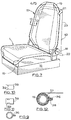
- Figure 7 is a perspective view of an alternative vehicle seat with the back rest in the normal, erected, postion,
- Figure 8 is a perspective view of the seat of Figure 7 with the back rest in the forwardly pivoted, lowered position and including an alternative further bed portion, also in the lowered position,
- Figure 9 is a section through a tube of the seat of Figure 7,
- Figures 10 and 11 are side and plan views on an enlarged scale of a fastener for securing material to a seat, and
- Figure 12 is an enlarged section on line 12-12 of Figure 7.
- Referring to Figures 1, 2 and 3 there is provided inside a vehicle cab at one side a driver's seat 1 which, in known manner (not shown), may be raised and lowered about a mean position and which may be adjusted forwards or backwards from a mean position to suit the driver. The range of vertical movement is generally of the order of 5 cm. up and down from the mean position. A passenger seat 2 is provided on a seat box (not shown) at the other side of the cab and the position of this is fixed. Each seat has a
seat portion 3 and aback rest 4 which is hinged at 5 to the seat portion. Abed portion 6 is secured to the back of eachback rest 4. When the back rest is pivoted forwardly and downwardly to the position shown at 4a in Figure 1 the bed portion takes up the position shown at 6a and is locked in that position, for example by means of a conventional spring loaded pawl and notch mechanism between the back rest and hinge structure or by a restraining strap, to prevent rocking of the bed portion when in use. - A support, which may conveniently be a
locker 7, is hinged to the floor of the cab at 8 and may be rotated about the hinge to a forward position shown in broken lines at 7a in Figures 1 and 3. - A
further bed portion 9 of generally rectangular shape is hinged to the cabrear panel 11 at 12 and is retained in a vertical stored position bystraps 13 releasably secured between thepanel 11 andbed portion 9. - With the
locker 7 in theforward position 7a, thestraps 13 are released andbed portion 9 is pivoted forwardly and downwardly to the position shown at 9a in which its upper surface is aligned with the upper surfaces ofbed portions 6 in theirpositions 6a, the driver's seat 1 being assumed to be in alignment with the passenger seat, for example at the mean position of adjustment of the driver's seat. Thus the threebed portions - It will be appreciated that since the
bed portion 9 is in a central position when stowed at the back of the cab it will not obscure vision out of rear side windows of the cab nor will it obscure vision through side windows, if provided, in the cab rear panel, that is, behind the seats. The construction which has been described also results in some weight saving because the structure of the seats is used to provide bed support at each end of the bunk. - Referring now to Figures 4, 5 and 6, the seats with back rests and the
further bed portion 9 are similar to those in the construction of Figures 1, 2 and 3. Thebed portion 9 in the arrangement shown in Figures 4, 5 and 6, however, is located forward of its position in Figures 1, 2 and 3 enabling asecond bunk 14 to be stowed behind it. - The
bunk 14 extends across the back of the cab and is hinged at 15 to the cabrear panel 11. - When the lower bunk has been set in position, as described with reference to Figures 1, 2 and 3, the
upper bunk 14 may be pivoted forwardly and upwardly abouthinge 15 to the position shown at 14a. The upper bunk may be retained in the raised position by straps depending from the cab structure or by any other suitable means. - The support means for the lower, or single, bunk may comprise a fixed member such as a tubular metal support provided that this can be arranged so as not to interfere with the normal operation of the vehicle.
- The bed portions on'the back rests of the seats may be integral with the back rests or may be separate components secured to the back rests. The bed portions and the
further bed portion 9 may be cushioned and one of the bed portions may be stepped or formed so as to provide a pillow. - As illustrated, the driver's seat 1 is for a left hand drive vehicle but the driver's seat, which is an adjustable seat, may, of course, be provided on the right hand side and the fixed seat 2 on the left hand side if desired.
- Referring now to Figures 7 to 11, the seat 1, Figure 7, is shown mounted on a
base 15 which may represent a fixed mounting for the seat or, as is usual for the driver's seat, a mechanism for forward and aft and vertical adjustment of the seat. - The seat has a
tubular frame 16 to which an upholstery material is secured. The seat has aback rest 17 which is pivoted at 18 to the seat frame. The back rest, in known manner, may be adjusted to and locked in different angular positions relative to the seat frame, if desired. - The
back rest 17 has atubular frame 19 to which an upholstery material is secured. Upper and lowertubular elements frame 19. Apanel 23 of material, which may be the same as the upholstery material, is secured between theelements back rest 17 may be folded forwards so that thepanel 23 lies substantially horizontally and, in conjunction with the back rest and seat forms onebed portion 40 of a bunk which is comprised of two similar bed portions and a central further bed portion (25). - Referring now to Figure 8, the seat 1 is shown with the back rest in the lowered position forming one end portion of a bunk. In this case the upper and
lower elements additional element 24 which joins them so that the three elements form a generally U-shaped member secured to theback rest 17. The material of thepanel 23 is secured along one side edge to theadditional element 24 as well as being secured between the upper andlower elements - The further bed portion 25 is shown in the lowered position in Figure 8. It has upper and lower
elongate elements panel 28 of material is secured. Thelower element 27 is hingedly secured at 29 to therear wall 11 of the cab.U-shaped support members struts 33, are pivotally secured to each end of theelements support members support members hinges 29 are so dimensioned and located that when the further bed portion is folded down the upper andlower elements lower elements rest 17. - The
panel 28 includes aflap 34, 35 at each end. The free edges of flap 34 and ofpanel 23 are fitted with releasable inter-acting adhesive fastening strips, for example "Velcro" (Registered Trade Mark) strip, so thatpanels support member 32 and is of similar construction to that of seat 1. Theflap 35 may be similarly secured to the free edge of thepanel 23 of the second seat so that a continuous bunk is formed by the seats and further bed portion. - When the bunk is not required the
flaps 34, 35 are released and folded back, as shown in the case offlap 35. The further bed portion 25 is hinged up into a position adjacent thewall 11 of the cab and secured by suitable means, not shown. Thesupport members lower elements further bed portion 9 of Figures 1 to 6. - Referring now to Figures 9 to 12, the tubes forming the frames of the seats, back rests and upper, lower and additional elements to which material is required to be attached may be provided with
strips 36, secured as by welding. Padding 37, for example plastic foam padding, may be fitted around the tube except in the way of thestrip 36. The edge of the material is placed over the strips andspring fasteners 38 are applied at intervals along the length of thestrip 36. These fasteners havetangs 39 which grip the material. The material is brought round the padded tube, tensioned, and secured in like manner to the corresponding tube on the opposite side of the seat frame, back rest or elements of the bunk. Where a panel, for example thepanel 23 orpanel 28, has a free edge or edges it may be found that tensioning of the material between the upper and lower elements, 21, 22 and 26, 27, causes the free edge or edges to be drawn in. Where this is likely to occur the or each free edge is cut initially in a curve or arc of a circle (along which the fastening strip is secured) and this becomes a straight line edge when the panel is fitted and tensioned and engagement of the mating Velcro fastening strips is thereby facilitated.
Claims (11)
1. A vehicle cab having first and second seats spaced laterally in the cab sustantially in alignment with one another and each seat having a back rest, characterised in that the back rest (4, 17) of each seat (1, 2) carries, or is adapted to carry, on its back a bed portion (6, 40) and each back rest (4, 17) is hinged relative to a seat portion (3) of the seat (1, 2) so as to be pivotable forwardly towards the seat portion (3) into a lowered position whereby the bed portion (6, 23) can take up a substantially horizontal position, a further bed portion (9, 25) is provided which is dimensioned and shaped so as to fit between the bed portions (6, 40) on the back rests (4, 17), support means (31, 32) support the further bed portion (6, 40) between the seats (1, 2) whereby the three bed portions (6, 40, 9, 25) may be arranged substantially horizontally and substantially in alignment to constitute a bunk, and means (13) are provided for storing the further bed portion (6, 40) in the cab when not required for formation of the bunk.
2. A vehicle cab as claimed in Claim 1 characterised in that the bed portion (6) associated with each seat (1, 2) is integral with the back rest (4) and is cushioned.
3. A vehicle cab as claimed in Claim 1 characterised in that the bed portion (40) associated with each seat (1, 2) comprises first and second elements (21, 22) fixed to the back rest (17) at positions such that they are vertically spaced when the back rest (17) is erect, and a panel (23) of upholstery material having opposed sides connected between the elements (21, 22).
4. A vehicle cab as claimed in Claim 3 characterised in that a third element (24) is secured to the back rest (17) of at least one seat (1, 2) on that side of the seat adjacent the side of the cab and a corresponding end of the panel (23) of material is secured to said third element (24).
5. A vehicle cab as claimed in Claim 1 or Claim 2 characterised in that the further bed portion (9) comprises a generally rectangular cushioned member having one side pivotally secured to a mounting in the cab.
6. A vehicle cab as claimed in any of Claims 1, 3 or 4 characterised in that the further bed portion (25) comprises ° two elongate elements (26, 27) which are disposed in parallel spaced apart relationship extending transversely of the cab and one of which is pivoted to a fixed mounting (11) in the cab, and a panel (28) of material having opposed sides secured to the elongate elements (26, 27).
7. A vehicle cab as claimed in Claim 6 characterised in that the elongate elements (26, 27) are secured in spaced apart relatonship by support means comprising a support member (31, 32) at or towards each end, which support member (31, 32) is hingedly connected between the elongate elements (26, 27).
8. A vehicle cab as claimed in Claim 6 or Claim 7 as dependent from Claim 3 or Claim 4 characterised in that means (34, 35) is provided releasably to connect adjacent ends of the panels (23, 28) on the bed portion (40) of a back rest (17) and the further bed portion (25).
9. A vehicle cab as claimed in any of Claims 3, 4, 6 to 8 characterised in that at least one of the panels (23, 28) of material in the free state before being secured to the bed portion (40), or further bed portion (25) as the case may be, has an arcuately shaped end whereby when said panel (23, 28) is secured under tension between the first and second elements (21, 22), or between the elongate elements (26, 27) as the case may be, said end becomes straight to facilitate its connection to the end of an adjacent panel (23, 28).
100 A vehicle cab as claimed in any preceding claim characterised in that a second bunk (14) is stored in a, or substantially a, vertical position extending across the back of the cab behind the further bed portion (9) and arranged so that, with the further bed portion (9) in the horizontal position, the second bunk (14) may be erected above and spaced vertically from the bunk comprised of the three bed portions (6, 9).
11. A vehicle cab as claimed in any preceding claim characterised in that means are provided to secure the back rests (14, 17) in the lowered positions and so inhibit rocking of the bed portions (6, 40) carried thereby.
Applications Claiming Priority (4)
| Application Number | Priority Date | Filing Date | Title |
|---|---|---|---|
| GB8009667 | 1980-03-21 | ||
| GB8009667 | 1980-03-21 | ||
| GB8030165 | 1980-09-18 | ||
| GB8030165 | 1980-09-18 |
Publications (1)
| Publication Number | Publication Date |
|---|---|
| EP0036758A1 true EP0036758A1 (en) | 1981-09-30 |
Family
ID=26274923
Family Applications (1)
| Application Number | Title | Priority Date | Filing Date |
|---|---|---|---|
| EP81301168A Ceased EP0036758A1 (en) | 1980-03-21 | 1981-03-18 | Sleeping arrangement for drivers' cabs |
Country Status (2)
| Country | Link |
|---|---|
| EP (1) | EP0036758A1 (en) |
| GB (1) | GB2074510B (en) |
Cited By (9)
| Publication number | Priority date | Publication date | Assignee | Title |
|---|---|---|---|---|
| DE3814537A1 (en) * | 1988-04-29 | 1989-11-09 | Man Nutzfahrzeuge Ag | Bunk for the driver's cab of a lorry |
| US5029929A (en) * | 1989-02-15 | 1991-07-09 | Saab-Scania Aktiebolag | Bed arrangement in the coupe area of a vehicle |
| DE4335909A1 (en) * | 1993-10-21 | 1995-04-27 | Asmus Dolan | Kit for reversibly converting passenger cars into small camper vans |
| FR2720793A1 (en) * | 1994-06-07 | 1995-12-08 | Jean Fantini | Profiles for fixing supple sheet material or film |
| WO2002012015A1 (en) * | 2000-08-04 | 2002-02-14 | Volvo Lastvagnar Ab | A combination of chair and bed |
| EP1288113A3 (en) * | 2001-08-28 | 2003-09-03 | DaimlerChrysler AG | Cabin for a utility vehicule |
| FR2875210A1 (en) * | 2004-09-13 | 2006-03-17 | Renault V I Sa | SELF-ENGINE VEHICLE CAB |
| WO2006055005A1 (en) * | 2004-11-19 | 2006-05-26 | Volvo Trucks North America | Dual berth invertible bunk |
| EP2022708A2 (en) | 2007-08-08 | 2009-02-11 | MAN Nutzfahrzeuge Aktiengesellschaft | Bed frame for a bed of a utility vehicle driver cab |
Families Citing this family (2)
| Publication number | Priority date | Publication date | Assignee | Title |
|---|---|---|---|---|
| GB2178648A (en) * | 1985-01-21 | 1987-02-18 | John Burgess | Convertible vehicle seats |
| RU2216460C2 (en) * | 2000-11-23 | 2003-11-20 | Федеральное государственное унитарное предприятие "Производственное объединение "Ульяновский машиностроительный завод" | Device to adjust relative position of backrest and cushion of vehicle seat |
Citations (5)
| Publication number | Priority date | Publication date | Assignee | Title |
|---|---|---|---|---|
| US2806510A (en) * | 1956-05-18 | 1957-09-17 | Eugene D Walker | Seat-bed |
| GB1310056A (en) * | 1970-12-10 | 1973-03-14 | Holdsworth Conversions Ltd Ric | Convertible bed structure in a motor vehicle |
| US4005898A (en) * | 1975-03-18 | 1977-02-01 | Way Lee V | Convertible seat/bed structure and associated foldable table for pickup trucks and the like |
| CH590142A5 (en) * | 1974-04-01 | 1977-07-29 | Compin Ets | |
| GB2011252A (en) * | 1977-12-16 | 1979-07-11 | Compin Ets | Self-supporting modular bunk unit |
-
1981
- 1981-03-18 EP EP81301168A patent/EP0036758A1/en not_active Ceased
- 1981-03-19 GB GB8108694A patent/GB2074510B/en not_active Expired
Patent Citations (5)
| Publication number | Priority date | Publication date | Assignee | Title |
|---|---|---|---|---|
| US2806510A (en) * | 1956-05-18 | 1957-09-17 | Eugene D Walker | Seat-bed |
| GB1310056A (en) * | 1970-12-10 | 1973-03-14 | Holdsworth Conversions Ltd Ric | Convertible bed structure in a motor vehicle |
| CH590142A5 (en) * | 1974-04-01 | 1977-07-29 | Compin Ets | |
| US4005898A (en) * | 1975-03-18 | 1977-02-01 | Way Lee V | Convertible seat/bed structure and associated foldable table for pickup trucks and the like |
| GB2011252A (en) * | 1977-12-16 | 1979-07-11 | Compin Ets | Self-supporting modular bunk unit |
Cited By (13)
| Publication number | Priority date | Publication date | Assignee | Title |
|---|---|---|---|---|
| DE3814537A1 (en) * | 1988-04-29 | 1989-11-09 | Man Nutzfahrzeuge Ag | Bunk for the driver's cab of a lorry |
| US5029929A (en) * | 1989-02-15 | 1991-07-09 | Saab-Scania Aktiebolag | Bed arrangement in the coupe area of a vehicle |
| DE4335909A1 (en) * | 1993-10-21 | 1995-04-27 | Asmus Dolan | Kit for reversibly converting passenger cars into small camper vans |
| FR2720793A1 (en) * | 1994-06-07 | 1995-12-08 | Jean Fantini | Profiles for fixing supple sheet material or film |
| US6845531B2 (en) | 2000-08-04 | 2005-01-25 | Volvo Lastvagnar Ab | Combination for chair and bed |
| WO2002012015A1 (en) * | 2000-08-04 | 2002-02-14 | Volvo Lastvagnar Ab | A combination of chair and bed |
| EP1288113A3 (en) * | 2001-08-28 | 2003-09-03 | DaimlerChrysler AG | Cabin for a utility vehicule |
| FR2875210A1 (en) * | 2004-09-13 | 2006-03-17 | Renault V I Sa | SELF-ENGINE VEHICLE CAB |
| WO2006030155A1 (en) | 2004-09-13 | 2006-03-23 | Renault Trucks | Cabin of a self-propelled vehicle |
| WO2006055005A1 (en) * | 2004-11-19 | 2006-05-26 | Volvo Trucks North America | Dual berth invertible bunk |
| US7543340B2 (en) * | 2004-11-19 | 2009-06-09 | Volvo Trucks North America | Dual berth invertible bunk |
| EP2022708A2 (en) | 2007-08-08 | 2009-02-11 | MAN Nutzfahrzeuge Aktiengesellschaft | Bed frame for a bed of a utility vehicle driver cab |
| EP2022708A3 (en) * | 2007-08-08 | 2009-06-24 | MAN Nutzfahrzeuge Aktiengesellschaft | Bed frame for a bed of a utility vehicle driver cab |
Also Published As
| Publication number | Publication date |
|---|---|
| GB2074510B (en) | 1983-08-17 |
| GB2074510A (en) | 1981-11-04 |
Similar Documents
| Publication | Publication Date | Title |
|---|---|---|
| US4602816A (en) | Motor vehicle sling seat | |
| US4943105A (en) | Automobile pet seat and cargo carrier | |
| US8573664B2 (en) | Pet barrier and cover | |
| US4986600A (en) | Collapsible infant seat | |
| US3951450A (en) | Infant seat for automotive and other vehicles | |
| US5029928A (en) | Pickup truck bed seat | |
| US4443034A (en) | Folding platform and shelves for use in vehicles | |
| US6764132B1 (en) | Chair with integrated, retractable carry strap | |
| EP1354760B1 (en) | A movable bulkhead for a van | |
| US7210426B2 (en) | Compressible pet carrier | |
| US3730294A (en) | Foldable, readily-transportable seat | |
| US4679840A (en) | Seat for a truck bed | |
| US4681367A (en) | Auxiliary seat | |
| US8567846B1 (en) | Vehicle having utility bed including seat | |
| EP0036758A1 (en) | Sleeping arrangement for drivers' cabs | |
| US7052026B2 (en) | Bracket device for bicycle trailer frames | |
| EP0154427A2 (en) | Child's vehicle seat | |
| US5054853A (en) | Infant safety chairs | |
| US6497444B1 (en) | Radiation shield for occupants of golf carts | |
| US11964602B2 (en) | Support system providing a supporting surface for rest in a vehicle | |
| US6163900A (en) | Folding RV furniture | |
| US4962709A (en) | Auxiliary vehicle deck | |
| US4487451A (en) | Sleeper seat | |
| US4458939A (en) | Vehicle, especially camping vehicle | |
| US4858986A (en) | Automobile-mounted camper |
Legal Events
| Date | Code | Title | Description |
|---|---|---|---|
| PUAI | Public reference made under article 153(3) epc to a published international application that has entered the european phase |
Free format text: ORIGINAL CODE: 0009012 |
|
| AK | Designated contracting states |
Designated state(s): DE FR IT NL SE |
|
| 17P | Request for examination filed |
Effective date: 19811024 |
|
| STAA | Information on the status of an ep patent application or granted ep patent |
Free format text: STATUS: THE APPLICATION HAS BEEN REFUSED |
|
| 18R | Application refused |
Effective date: 19831212 |
|
| RIN1 | Information on inventor provided before grant (corrected) |
Inventor name: TAYLOR, MERRICK WENTWORTH Inventor name: KERBY, GRAHAM SCOTT Inventor name: STRONG, TERENCE |