EP2021670B1 - Schläuchebetreffende verbesserungen - Google Patents
Schläuchebetreffende verbesserungen Download PDFInfo
- Publication number
- EP2021670B1 EP2021670B1 EP07732719.5A EP07732719A EP2021670B1 EP 2021670 B1 EP2021670 B1 EP 2021670B1 EP 07732719 A EP07732719 A EP 07732719A EP 2021670 B1 EP2021670 B1 EP 2021670B1
- Authority
- EP
- European Patent Office
- Prior art keywords
- mandrel
- hose
- tubular body
- layers
- gpa
- Prior art date
- Legal status (The legal status is an assumption and is not a legal conclusion. Google has not performed a legal analysis and makes no representation as to the accuracy of the status listed.)
- Not-in-force
Links
Images


Classifications
-
- F—MECHANICAL ENGINEERING; LIGHTING; HEATING; WEAPONS; BLASTING
- F16—ENGINEERING ELEMENTS AND UNITS; GENERAL MEASURES FOR PRODUCING AND MAINTAINING EFFECTIVE FUNCTIONING OF MACHINES OR INSTALLATIONS; THERMAL INSULATION IN GENERAL
- F16L—PIPES; JOINTS OR FITTINGS FOR PIPES; SUPPORTS FOR PIPES, CABLES OR PROTECTIVE TUBING; MEANS FOR THERMAL INSULATION IN GENERAL
- F16L11/00—Hoses, i.e. flexible pipes
- F16L11/04—Hoses, i.e. flexible pipes made of rubber or flexible plastics
- F16L11/08—Hoses, i.e. flexible pipes made of rubber or flexible plastics with reinforcements embedded in the wall
- F16L11/081—Hoses, i.e. flexible pipes made of rubber or flexible plastics with reinforcements embedded in the wall comprising one or more layers of a helically wound cord or wire
- F16L11/082—Hoses, i.e. flexible pipes made of rubber or flexible plastics with reinforcements embedded in the wall comprising one or more layers of a helically wound cord or wire two layers
-
- B—PERFORMING OPERATIONS; TRANSPORTING
- B29—WORKING OF PLASTICS; WORKING OF SUBSTANCES IN A PLASTIC STATE IN GENERAL
- B29C—SHAPING OR JOINING OF PLASTICS; SHAPING OF MATERIAL IN A PLASTIC STATE, NOT OTHERWISE PROVIDED FOR; AFTER-TREATMENT OF THE SHAPED PRODUCTS, e.g. REPAIRING
- B29C53/00—Shaping by bending, folding, twisting, straightening or flattening; Apparatus therefor
- B29C53/80—Component parts, details or accessories; Auxiliary operations
- B29C53/82—Cores or mandrels
- B29C53/821—Mandrels especially adapted for winding and joining
-
- B—PERFORMING OPERATIONS; TRANSPORTING
- B29—WORKING OF PLASTICS; WORKING OF SUBSTANCES IN A PLASTIC STATE IN GENERAL
- B29D—PRODUCING PARTICULAR ARTICLES FROM PLASTICS OR FROM SUBSTANCES IN A PLASTIC STATE
- B29D23/00—Producing tubular articles
- B29D23/001—Pipes; Pipe joints
-
- B—PERFORMING OPERATIONS; TRANSPORTING
- B32—LAYERED PRODUCTS
- B32B—LAYERED PRODUCTS, i.e. PRODUCTS BUILT-UP OF STRATA OF FLAT OR NON-FLAT, e.g. CELLULAR OR HONEYCOMB, FORM
- B32B1/00—Layered products having a non-planar shape
- B32B1/08—Tubular products
-
- B—PERFORMING OPERATIONS; TRANSPORTING
- B32—LAYERED PRODUCTS
- B32B—LAYERED PRODUCTS, i.e. PRODUCTS BUILT-UP OF STRATA OF FLAT OR NON-FLAT, e.g. CELLULAR OR HONEYCOMB, FORM
- B32B15/00—Layered products comprising a layer of metal
- B32B15/02—Layer formed of wires, e.g. mesh
-
- B—PERFORMING OPERATIONS; TRANSPORTING
- B32—LAYERED PRODUCTS
- B32B—LAYERED PRODUCTS, i.e. PRODUCTS BUILT-UP OF STRATA OF FLAT OR NON-FLAT, e.g. CELLULAR OR HONEYCOMB, FORM
- B32B27/00—Layered products comprising a layer of synthetic resin
- B32B27/06—Layered products comprising a layer of synthetic resin as the main or only constituent of a layer, which is next to another layer of the same or of a different material
- B32B27/08—Layered products comprising a layer of synthetic resin as the main or only constituent of a layer, which is next to another layer of the same or of a different material of synthetic resin
-
- B—PERFORMING OPERATIONS; TRANSPORTING
- B32—LAYERED PRODUCTS
- B32B—LAYERED PRODUCTS, i.e. PRODUCTS BUILT-UP OF STRATA OF FLAT OR NON-FLAT, e.g. CELLULAR OR HONEYCOMB, FORM
- B32B27/00—Layered products comprising a layer of synthetic resin
- B32B27/12—Layered products comprising a layer of synthetic resin next to a fibrous or filamentary layer
-
- B—PERFORMING OPERATIONS; TRANSPORTING
- B32—LAYERED PRODUCTS
- B32B—LAYERED PRODUCTS, i.e. PRODUCTS BUILT-UP OF STRATA OF FLAT OR NON-FLAT, e.g. CELLULAR OR HONEYCOMB, FORM
- B32B27/00—Layered products comprising a layer of synthetic resin
- B32B27/32—Layered products comprising a layer of synthetic resin comprising polyolefins
- B32B27/322—Layered products comprising a layer of synthetic resin comprising polyolefins comprising halogenated polyolefins, e.g. PTFE
-
- B—PERFORMING OPERATIONS; TRANSPORTING
- B32—LAYERED PRODUCTS
- B32B—LAYERED PRODUCTS, i.e. PRODUCTS BUILT-UP OF STRATA OF FLAT OR NON-FLAT, e.g. CELLULAR OR HONEYCOMB, FORM
- B32B5/00—Layered products characterised by the non- homogeneity or physical structure, i.e. comprising a fibrous, filamentary, particulate or foam layer; Layered products characterised by having a layer differing constitutionally or physically in different parts
- B32B5/02—Layered products characterised by the non- homogeneity or physical structure, i.e. comprising a fibrous, filamentary, particulate or foam layer; Layered products characterised by having a layer differing constitutionally or physically in different parts characterised by structural features of a fibrous or filamentary layer
- B32B5/024—Woven fabric
-
- B—PERFORMING OPERATIONS; TRANSPORTING
- B32—LAYERED PRODUCTS
- B32B—LAYERED PRODUCTS, i.e. PRODUCTS BUILT-UP OF STRATA OF FLAT OR NON-FLAT, e.g. CELLULAR OR HONEYCOMB, FORM
- B32B5/00—Layered products characterised by the non- homogeneity or physical structure, i.e. comprising a fibrous, filamentary, particulate or foam layer; Layered products characterised by having a layer differing constitutionally or physically in different parts
- B32B5/18—Layered products characterised by the non- homogeneity or physical structure, i.e. comprising a fibrous, filamentary, particulate or foam layer; Layered products characterised by having a layer differing constitutionally or physically in different parts characterised by features of a layer of foamed material
-
- B—PERFORMING OPERATIONS; TRANSPORTING
- B32—LAYERED PRODUCTS
- B32B—LAYERED PRODUCTS, i.e. PRODUCTS BUILT-UP OF STRATA OF FLAT OR NON-FLAT, e.g. CELLULAR OR HONEYCOMB, FORM
- B32B5/00—Layered products characterised by the non- homogeneity or physical structure, i.e. comprising a fibrous, filamentary, particulate or foam layer; Layered products characterised by having a layer differing constitutionally or physically in different parts
- B32B5/22—Layered products characterised by the non- homogeneity or physical structure, i.e. comprising a fibrous, filamentary, particulate or foam layer; Layered products characterised by having a layer differing constitutionally or physically in different parts characterised by the presence of two or more layers which are next to each other and are fibrous, filamentary, formed of particles or foamed
- B32B5/24—Layered products characterised by the non- homogeneity or physical structure, i.e. comprising a fibrous, filamentary, particulate or foam layer; Layered products characterised by having a layer differing constitutionally or physically in different parts characterised by the presence of two or more layers which are next to each other and are fibrous, filamentary, formed of particles or foamed one layer being a fibrous or filamentary layer
- B32B5/245—Layered products characterised by the non- homogeneity or physical structure, i.e. comprising a fibrous, filamentary, particulate or foam layer; Layered products characterised by having a layer differing constitutionally or physically in different parts characterised by the presence of two or more layers which are next to each other and are fibrous, filamentary, formed of particles or foamed one layer being a fibrous or filamentary layer another layer next to it being a foam layer
-
- B—PERFORMING OPERATIONS; TRANSPORTING
- B32—LAYERED PRODUCTS
- B32B—LAYERED PRODUCTS, i.e. PRODUCTS BUILT-UP OF STRATA OF FLAT OR NON-FLAT, e.g. CELLULAR OR HONEYCOMB, FORM
- B32B5/00—Layered products characterised by the non- homogeneity or physical structure, i.e. comprising a fibrous, filamentary, particulate or foam layer; Layered products characterised by having a layer differing constitutionally or physically in different parts
- B32B5/22—Layered products characterised by the non- homogeneity or physical structure, i.e. comprising a fibrous, filamentary, particulate or foam layer; Layered products characterised by having a layer differing constitutionally or physically in different parts characterised by the presence of two or more layers which are next to each other and are fibrous, filamentary, formed of particles or foamed
- B32B5/24—Layered products characterised by the non- homogeneity or physical structure, i.e. comprising a fibrous, filamentary, particulate or foam layer; Layered products characterised by having a layer differing constitutionally or physically in different parts characterised by the presence of two or more layers which are next to each other and are fibrous, filamentary, formed of particles or foamed one layer being a fibrous or filamentary layer
- B32B5/26—Layered products characterised by the non- homogeneity or physical structure, i.e. comprising a fibrous, filamentary, particulate or foam layer; Layered products characterised by having a layer differing constitutionally or physically in different parts characterised by the presence of two or more layers which are next to each other and are fibrous, filamentary, formed of particles or foamed one layer being a fibrous or filamentary layer another layer next to it also being fibrous or filamentary
-
- F—MECHANICAL ENGINEERING; LIGHTING; HEATING; WEAPONS; BLASTING
- F16—ENGINEERING ELEMENTS AND UNITS; GENERAL MEASURES FOR PRODUCING AND MAINTAINING EFFECTIVE FUNCTIONING OF MACHINES OR INSTALLATIONS; THERMAL INSULATION IN GENERAL
- F16L—PIPES; JOINTS OR FITTINGS FOR PIPES; SUPPORTS FOR PIPES, CABLES OR PROTECTIVE TUBING; MEANS FOR THERMAL INSULATION IN GENERAL
- F16L59/00—Thermal insulation in general
- F16L59/14—Arrangements for the insulation of pipes or pipe systems
- F16L59/141—Arrangements for the insulation of pipes or pipe systems in which the temperature of the medium is below that of the ambient temperature
-
- B—PERFORMING OPERATIONS; TRANSPORTING
- B29—WORKING OF PLASTICS; WORKING OF SUBSTANCES IN A PLASTIC STATE IN GENERAL
- B29C—SHAPING OR JOINING OF PLASTICS; SHAPING OF MATERIAL IN A PLASTIC STATE, NOT OTHERWISE PROVIDED FOR; AFTER-TREATMENT OF THE SHAPED PRODUCTS, e.g. REPAIRING
- B29C53/00—Shaping by bending, folding, twisting, straightening or flattening; Apparatus therefor
- B29C53/56—Winding and joining, e.g. winding spirally
- B29C53/58—Winding and joining, e.g. winding spirally helically
- B29C53/60—Winding and joining, e.g. winding spirally helically using internal forming surfaces, e.g. mandrels
-
- B—PERFORMING OPERATIONS; TRANSPORTING
- B32—LAYERED PRODUCTS
- B32B—LAYERED PRODUCTS, i.e. PRODUCTS BUILT-UP OF STRATA OF FLAT OR NON-FLAT, e.g. CELLULAR OR HONEYCOMB, FORM
- B32B2262/00—Composition or structural features of fibres which form a fibrous or filamentary layer or are present as additives
- B32B2262/02—Synthetic macromolecular fibres
- B32B2262/0253—Polyolefin fibres
-
- B—PERFORMING OPERATIONS; TRANSPORTING
- B32—LAYERED PRODUCTS
- B32B—LAYERED PRODUCTS, i.e. PRODUCTS BUILT-UP OF STRATA OF FLAT OR NON-FLAT, e.g. CELLULAR OR HONEYCOMB, FORM
- B32B2262/00—Composition or structural features of fibres which form a fibrous or filamentary layer or are present as additives
- B32B2262/02—Synthetic macromolecular fibres
- B32B2262/0261—Polyamide fibres
- B32B2262/0269—Aromatic polyamide fibres
-
- B—PERFORMING OPERATIONS; TRANSPORTING
- B32—LAYERED PRODUCTS
- B32B—LAYERED PRODUCTS, i.e. PRODUCTS BUILT-UP OF STRATA OF FLAT OR NON-FLAT, e.g. CELLULAR OR HONEYCOMB, FORM
- B32B2597/00—Tubular articles, e.g. hoses, pipes
-
- Y—GENERAL TAGGING OF NEW TECHNOLOGICAL DEVELOPMENTS; GENERAL TAGGING OF CROSS-SECTIONAL TECHNOLOGIES SPANNING OVER SEVERAL SECTIONS OF THE IPC; TECHNICAL SUBJECTS COVERED BY FORMER USPC CROSS-REFERENCE ART COLLECTIONS [XRACs] AND DIGESTS
- Y10—TECHNICAL SUBJECTS COVERED BY FORMER USPC
- Y10T—TECHNICAL SUBJECTS COVERED BY FORMER US CLASSIFICATION
- Y10T29/00—Metal working
- Y10T29/49—Method of mechanical manufacture
- Y10T29/49428—Gas and water specific plumbing component making
- Y10T29/49435—Flexible conduit or fitting therefor
-
- Y—GENERAL TAGGING OF NEW TECHNOLOGICAL DEVELOPMENTS; GENERAL TAGGING OF CROSS-SECTIONAL TECHNOLOGIES SPANNING OVER SEVERAL SECTIONS OF THE IPC; TECHNICAL SUBJECTS COVERED BY FORMER USPC CROSS-REFERENCE ART COLLECTIONS [XRACs] AND DIGESTS
- Y10—TECHNICAL SUBJECTS COVERED BY FORMER USPC
- Y10T—TECHNICAL SUBJECTS COVERED BY FORMER US CLASSIFICATION
- Y10T29/00—Metal working
- Y10T29/49—Method of mechanical manufacture
- Y10T29/4981—Utilizing transitory attached element or associated separate material
Definitions
- This invention relates to hose, and more particularly relates to long length hose, and to a method for making it.
- the invention is especially concerned with hose which can be used in cryogenic conditions.
- Typical applications for hose involve the pumping of fluids from a fluid reservoir under pressure. Examples include supplying of domestic heating oil or LPG to a boiler; transporting produced oilfield liquids and/or gases from a fixed or floating production platform to the cargo hold of a ship, or from a ship cargo hold to a land-based storage unit; delivering of fuel to racing cars, especially during refuelling in formula 1; and conveying corrosive fluids, such as sulphuric acid.
- hose for the transport of fluids, such as liquefied gases, at low temperature.
- fluids such as liquefied gases
- hose is commonly used to transport liquefied gases such as liquefied natural gas (LNG) and liquefied propane gas (LPG).
- LNG liquefied natural gas
- LPG liquefied propane gas
- hose Many applications of hose require the hose to be supported along its length. This especially applies to the transport of the produced liquids and/or gases mentioned above. Without additional support, conventional hose is often incapable of supporting its own weight, or the weight of the fluid contained therein.
- the present invention is directed to composite hoses.
- Rubber hoses differ from composite and bellows hose in that they do not have a steel component on the inner surface.
- Rubber hoses are typically manufactured by wrapping numerous layers of rubber materials and some steel and fabric layers around a mandrel coated with a release agent. Some Rubber Hoses use an extruded rubber inner liner on a mandrel as the innermost layer and then wrap after that. Other rubber hoses include an interlocked carcass inside the liner, for collapse resistance. The complete structure is then vulcanised thus bonding the rubber wraps together. The complete hose assembly, including the end fittings which are also on the mandrel and are wrapped into the hose body structure, is removed from the mandrel by pulling and rotating. The hose and mandrel are supported by a series of rollers during this extraction process. Rubber hoses are typically made in lengths of up to 12m and bores of up to at least 1.2m.
- a bellows hose is formed in sections supported on steel mandrel and if insulating or protective layers are required these will be wrapped around the bellows tube.
- a composite hose is traditionally formed by a steel wire being wound helically onto a steel mandrel followed by a number of film and fabric layers. This is then formed into the hose body by the application of a second helical wire.
- Both bellows and composite hoses are widely available in bores of up to 200mm and in lengths of up to about 30m. However it is difficult to manufacture and extract a large bore hose, greater than 400mm, of either of these types in a reasonable length, greater than 10m, using the traditional manufacturing techniques. This is not the case with rubber hoses as they do not have an inner steel component.
- Composite hose is described in many prior art documents, including, for example, EP-0076540A1 and WO01/96772 .
- this type of hose is characterised by an inner metallic inner structure which is difficult to remove from the mandrel during the manufacturing process.
- there is a practical limit on the size of hose which can be produced in the prior art while at the same time retaining the ability to operate in hostile environments, such as in conditions of low and high temperature; and in marine applications.
- GB2303574 , DE2948416 , JP08336845 , JP08011138 and JP03075132 disclose a method of making hose or tubing, but they do not disclose the manufacture of bellows hose.
- US 3,287,194 A discloses a method of making a flexible corrugated conduit, such as for use in vacuum cleaners, hairdryers, automotive cooling systems and the like, by placing a coil over a compressible mandrel, placing an outer tubular member over the coil, and placing the assembly within a vacuum box in order to collapse the tubular member onto the coil and mandrel.
- US 3,240,643 A discloses a method and apparatus for making a flexible insulated duct, e.g. for use in heating and air-conditioning of buildings, using a rotating mandrel.
- Bellows hose is exclusively manufactured on a metallic mandrel; the mandrel may consist exclusively of the stainless steel or may be clad with stainless steel.
- a carbon steel mandrel might typically cost about £5,000 and in its working lifetime it would be capable of being used to manufacture about 25-30 individual hoses.
- the metallic inner member of the hose is often made of stainless steel.
- part of the carbon steel can be transferred to the surface of the stainless steel inner member; this causes a site for corrosion of the inner member, which can lead to rapid failure in extreme environments.
- the mandrel used in the manufacture of bellows hose and composite hose usually has to be made of stainless steel.
- a stainless steel hose costs three to four times as much as a carbon steel mandrel.
- a hose comprising a tubular hose portion extending continuously between two end fittings, wherein said hose portion comprises a tubular body disposed between inner and outer gripping members, wherein the tubular body comprises at least one sealing layer and at least one reinforcing layer, and wherein the internal diameter of the hose portion is at least 200mm and the length of the hose portion is at least 30m.
- the hose portion extends continuously between the end fittings.
- the hose according to this example is distinct from prior art hose comprising shorter lengths of hose which are attached together in sequence by attaching the end fittings together.
- the length of the hose portion is at least 31m, more preferably at least 32m.
- the hose portion is desirably at least 35m in length.
- the length of the hose portion may be much longer than 30m, depending on the requirements.
- the hose portion might have a length of up to 50m or even up to 60m.
- the length of the hose portion will typically lie within the ranges discussed above, subject to the minimum of at least 30m.
- the inner diameter of the hose portion is preferably at least 100mm, or at least 150mmm, or at least 200mm, or at least 250mm, more preferably at least 300mm, and still more preferably at least 350mm and most preferably at least 400mm.
- the hose portion inner diameter may be at least 450mm, at least 500mm, at least 550mm or at least 600mm. It is unlikely to be desirable for the hose portion diameter to exceed 750mm, and typically the hose portion diameter would not exceed 600mm.
- the hose portion has a length of from 30m or 35m up to about 50m, in combination with an inner diameter from 200mm to 600mm, preferably from 300mm to 600mm, most preferably 400mm to 600mm.
- a hose comprising a tubular hose portion extending continuously between two end fittings, wherein said hose portion comprises a tubular body disposed between inner and outer gripping members, wherein the tubular body comprises at least one sealing layer and at least one reinforcing layer, and wherein the internal diameter of the hose portion is at least 300mm and the length of the hose portion is at least 5m.
- the length of the hose portion is at least 8m, more preferably at least 10m, more preferably at least 15m, still more preferably at least 20m, or at least 25m.
- the hose portion may be at least 30m in length.
- the length of the hose portion may be much longer than 30m, depending on the requirements.
- the hose portion might have a length of up to 50m or even up to 60m.
- the inner diameter of the hose portion is preferably at least preferably at least 350mm and most preferably at least 400mm.
- the hose portion inner diameter may be at least 450mm, at least 500mm, at least 550mm or at least 600mm. It is unlikely to be desirable for the hose portion diameter to exceed 750mm, and typically the hose portion diameter would not exceed 600mm.
- the hose portion has a length of from 8m or 10m up to about 50m, in combination with an inner diameter from 400mm to 600mm.
- the inner diameter of the hose portion corresponds to the outer diameter of the non-metallic mandrel on which it was formed.
- the length of the hose portion corresponds to the distance between the end fittings immediately after manufacture of the hose. It should also be noted, that owing to the nature of the materials and the manufacturing process, the hose dimensions would usually be subject to a tolerance of about +/- 3%.
- the described hose may have a high or low working temperature, including a cryogenic working temperature.
- the working temperature of the hose may be at least 40°C, or at least 60°C, or at least 80°C or at least 100°C, up to a maximum of 200°C or 300°C.
- the working temperature of the hose may be from 0°C down to -200°C or -220°C.
- the working temperature is -20°C or below, -40°C or below, -60°C or below, or -80°C or below.
- the working temperature will typically be from -100°C to -170°C, -200°C or -220°C.
- a working temperature range from -100°C to -220°C is suitable for most cryogenic applications, including the transportation of LNG, liquid oxygen (bp - 183°C) or liquid nitrogen (bp -196°C).
- the working pressure of the hose is be in the range from about 500 kPa gauge, or 1,000kPa gauge, up to about 2,000 kPa gauge, or possibly up to about 2,500 kPa gauge. These pressures relate to the operating pressure of the hose, not the burst pressure (which must be several times greater).
- the working volumetric flow rate depends upon the fluid medium, the pressure and the inner diameter. Working flowrates from 1,000 m 3 /h up to 12,000 m 3 /h are typical.
- a preferred working temperature and pressure would be from -100°C to -200°C at a pressure from 500kPa gauge, preferably 1,000kPa gauge, up to 2,000kPa gauge or 2,500kPa gauge.
- the hose can also be provided for use with corrosive materials, such as strong acids.
- hose described above in the working temperature, working pressure, and/or working flowrates described above to transport a liquid through the hose without any leakage of the liquid through the hose.
- the inner gripping member is preferably a helical gripping member, and is most preferably a wire.
- the outer gripping member is preferably a helical gripping member, and is most preferably a wire.
- the inner gripping member and/or the outer gripping member is a metal, preferably stainless steel.
- the tubular body preferably comprises a sealing layer sandwiched between inner and outer reinforcing layers.
- the hose portion advantageously also includes axial strengthening means which is adapted to exert a radially inward force on at least part of the tubular body when the axial strengthening means is subjected to axial tensioning.
- the axial strengthening means is provided in the form of a generally tubular braid.
- braid refers to a material which is formed of two or more fibres or yarns which have been intertwined to form an elongated structure. It is a feature of braid that it can elongate when subjected to an axial tension. It is a further feature of braid that, when provided in a tubular form, its diameter will reduce when the braid is subjected to axial tension.
- the braid will exert a radially inward force on at least part of the tubular body when subjected to axial tension.
- the braid is preferably in the form of a tubular sheath which is applied to the hose structure by pulling it over the components of the hose that have already been arranged on the mandrel.
- the reinforcing layers and the sealing layer are preferably wrapped around the inner gripping member.
- the hose may also include one or more additional reinforcing layers, along with one or more insulation layers, and one or more layers to improve the buoyancy of the hose.
- the hose may include one or more protective layers. Preferably there is at least one protective layer overlying the outer gripping member.
- the most preferred composite hose for use in the present application is described in WO01/96772 , WO 2004/044472 and WO 2004/079248 .
- the structure of the hose may be substantially identical to the hose described in these publications, except that the present invention enables working hose to be produced which is longer and/or of greater diameter, owing to the improvements in the manufacturing process according to the invention.
- the end fittings for the hose may also be as described in the above three publications.
- the hose described above can be manufactured by a method and apparatus, as described further below, which makes it possible to make hose of longer length and diameter than has previously been possible.
- the end fittings are preferably applied before removing the hose from the mandrel, although they may in some circumstances be applied after removing the hose from the mandrel.
- the mandrel is formed of a paper based material, a wood based material or a plastics polymer based material, such as high density polyethylene, or mixtures thereof.
- the mandrel is cardboard, i.e. a board made of paper pulp.
- the mandrel In the manufacture of composite hose, it is particularly important to ensure that the mandrel has sufficient radial stiffness to withstand the large crushing forces applied during the formation of the hose portion. Thus, it is advantageous that the mandrel has sufficient radial stiffness that the hose portions can be formed on the mandrel without causing any substantial change to the cross-sectional shape of the mandrel.
- the mandrel is formed of a material having a ratio of Young's Modulus (E) to density ( ⁇ ) in the range 0.1 to 10 GPa.m 3 /Mg (i.e. giga Pascal x metre 3 /megagram).
- E Young's Modulus
- ⁇ density
- the ratio of E/ ⁇ is greater than 0.3 GPa.m 3 /Mg, more preferably greater than 0.5 GPa.m 3 /Mg, and most preferably greater than 0.8 GPa.m 3 /Mg.
- the ratio of E/ ⁇ is less than 10 GPa.m 3 /Mg, more preferably less than 5 GPa.m 3 /Mg, and most preferably less than 3 GPa.m 3 /Mg.
- the most preferred range of E/ ⁇ is from 0.8 to 3 GPa.m 3 /Mg.
- E/ ⁇ for cardboard and high density polyethylene which are two materials particularly preferred for the mandrel, are about 1.2 and 1.0 GPa.m 3 /Mg respectively.
- composite materials i.e., fibres disposed within a matrix
- Composite materials have a ratio of E/ ⁇ close to stainless steel, but the density is much lower.
- the material of the mandrel has an E/ ⁇ in the range 20 to 22 GPa.m 3 /Mg and a density in the range 1.0 to 3.0 Mg/m 3 .
- the composite material comprises carbon, glass or polymeric fibres disposed within a suitable polymeric matrix.
- the mandrel is made of a non-metallic material, it is perfectly possible for the mandrel to include metallic or ceramic fillers.
- the invention encompasses the use of a cardboard mandrel with a metallic or ceramic filler. The bulk of the mandrel, however, remains non-metallic.
- the mandrel may be provided in one continuous length, or it may be provided in a plurality of mandrel sections of shorter length, which are assembled on site to form the completed mandrel. The purpose of this is to facilitate transport of the mandrel.
- the mandrel is of substantially cylindrical shape.
- the length of the mandrel will typically be approximately 1000 to 2000 mm longer than the length of the hose portion that it is desired to make on the mandrel.
- the outer diameter of the mandrel will typically be substantially identical to the inner diameter of the hose portion that it is desired to make on the mandrel.
- the mandrel will typically have an outer diameter of 200mm, or 300mm to 600mm.
- the mandrel is hollow, so that a drive shaft may be disposed longitudinally within the mandrel.
- a plug is preferably disposed in at least one end of the mandrel, the arrangement being such that the plug is fixedly secured to the mandrel, whereby rotation of the plug causes rotation of the mandrel.
- one of said plugs is disposed in each end of the mandrel.
- the thickness of the hollow mandrel i.e. the difference between its inner and outer diameter
- the non-metallic mandrel should be made of a material which is strong enough that the mandrel can properly support the hose during construction thereof. Furthermore, except for any coating that may be provided on the inner or outer surface of the mandrel, the entire mandrel is preferably made of the same non-metallic material.
- the drive shaft is preferably secured to the or each plug, and desirably has a projecting end which can be connected to a drive motor, whereby rotation of the drive shaft causes rotation of the or each plug and thereby rotation of the mandrel. It is a preferred feature of the invention that the mandrel is rotated while part or all of the inner and/or outer structures are arranged in place on the mandrel.
- the drive motor is provided with a gearbox.
- the drive shaft may not be present, and the rotation of the mandrel may be driven by rotating one plug or both plugs (if present) using the drive motor.
- the mandrel is a sacrificial mandrel, in order to aid removal of the hose from the mandrel.
- the hose is removed from the mandrel by sacrificing the mandrel, and removing it from within the hose; any plugs and drive shaft can be removed before sacrificing the mandrel.
- the mandrel may be sacrificed by, for example, providing it with a pre-weakened area, which can be stressed in order to cause sacrifice of the mandrel; or providing it with a perforation, along which the mandrel can be torn apart; or providing it with a zipper structure, whereby dragging the zipper along the length of the mandrel causes sacrifice of the mandrel.
- Another technique for removing the mandrel when the mandrel is made from a material which can be weakened by contact with an appropriately selected fluid, is to wet the mandrel in order to weaken it with the fluid, then to remove the weakened mandrel.
- One way to wet mandrel is to dip the entire hose and mandrel structure in a tank of the fluid. It is preferred that the fluid is water, but other fluids, such as weak acetic acid or an alcoholic solution may instead be used.
- the mandrel is removed by unscrewing it from the hose.
- The can desirably be achieved by applying a torque to the drive shaft, while holding the hose against rotation.
- This technique is particularly suitable when the hose inner structure includes a helical member, as the helical member can create a slight indentation in the mandrel, which aids unscrewing the mandrel from the hose.
- the mandrel may be pre-coated, prior to assembly of the hose, in order to assist with removal of the completed hose from the mandrel.
- the precoat may serve to reduce the friction between the mandrel and the completed hose.
- apparatus for manufacturing hose of the type comprising a tubular hose portion extending continuously between two end fittings, wherein said hose portion comprises a tubular body disposed between inner and outer gripping members and the tubular body comprises at least two layers and includes at least one sealing layer and at least one reinforcing layer, wherein said apparatus comprises a hollow substantially cylindrical non-metallic mandrel, around which the hose may be arranged, a plug disposed at each end of the mandrel, the plugs being fixed to the mandrel, whereby torque applied to the plugs is transmitted to the mandrel to rotate the mandrel about its longitudinal axis, and a drive shaft extending longitudinally along the interior of the mandrel, the drive shaft being connected to the plugs, whereby torque applied to the drive shaft is transmitted to the plugs to rotate the plugs, the drive shaft projecting outwardly from the plugs and mandrel at least one end of the mandrel.
- the mandrel preferably has the same construction as the mandrel described above in relation to the method according to the invention.
- the drive shaft projects outwardly from the plugs and mandrel at each end of the mandrel.
- the apparatus further comprises a drive motor arranged to rotate the drive shaft.
- non-metallic mandrels can be removed from the completed hose much more easily than the prior art steel mandrels.
- the described non-metallic mandrels are much lighter than the steel mandrels used in the prior art. This means that they are easier to manipulate and transport. It also means that the non-metallic mandrels do not require the same level of support that is required for steel mandrels. This eases the manufacturing process for the hose.
- One particularly important advantage of the described mandrel is that it is practical to make them longer and/or of greater diameter than the prior art steel mandrels.
- a working hose is one which can be used in its normal operating conditions without leaking.
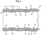
- Figure 1 a composite hose is generally designated 10. In order to improve the clarity the winding of the various layers in Figure 1 has not been shown.
- the hose 10 comprises a tubular body 12 which comprises an inner reinforcing layer 14, an outer reinforcing layer 16, and a sealing layer 18 sandwiched between the layers 14 and 16.
- a generally tubular sheath 20, which provides axial strengthening, is disposed around the outer surface of the outer reinforcing layer 16.
- the tubular body 12 and the tubular sheath 20 are disposed between an inner helically coiled wire 22 and an outer helically coiled wire 24.
- the inner and outer wires 22 and 24 are disposed so that they are offset from one another by a distance corresponding to half the pitch length of the helix of the coils.
- the insulation layer 26 is disposed around the outer wire 24.
- the insulation layer may be a conventional insulating material, such as a plastics foam, or may be a material described in relation to Figure 7 in WO01/96772 .
- the reinforcing layers 14 and 16 comprise woven fabrics of a synthetic material, such as UHMWPE or aramid fibres.
- a synthetic material such as UHMWPE or aramid fibres.
- the structure of suitable reinforcing layers is described in more detail in Figure 3 of WO01/96772 .
- the sealing layer 18 comprises a plurality of layers of plastics film which are wrapped around the outer surface of the inner reinforcing layer 14 to provide a fluid tight seal between the inner and outer reinforcing layers 14 and 16.
- the hose 10 may include a further reinforcing layer (not shown) disposed between the sheath 20 and the outer wires 24.
- the further reinforcing layer may have similar characteristics to the sheath 20 and the tubular body 12.
- the tubular sheath 20 is formed of two sets of fibres which are braided to form a tubular braid. This is shown in Figures 4A and 4B of WO01/96772 .
- the sealing layer 18 is shown in greater detail in Figure 6 of WO01/96772 .
- the sealing layer 18 comprises a plurality of layers of a film made of a first polymer (such as a highly oriented UHMWPE) interleaved with a plurality of layers of a film made of a second polymer (such as PFTE or FEP), the two polymers having a different stiffness.
- the layers are wrapped around the outer surface of the inner reinforcing layer 14 to provide a fluid tight seal between the inner and outer reinforcing layers 14 and 16.
- the sealing layer 18 may be made of a single type of polymer, i.e., it does not have to include two or more different types of polymer.
- the ends of the hose 10 may be sealed using the end fitting 200 shown in Figure 8 of WO01/96772 and/or as described in WO 2004/079248 .
- the end fittings are illustrated schematically in Figure 1 and are designated with reference numeral 28.
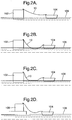
- FIGs 2A to 2D show three applications for the hose 10.
- a floating production, storage and offloading vessel (FPSO) 102 is linked to a LNG carrier 104 by means of a hose 10.
- the hose 10 carries LNG from a storage tank of the FPSO 102 to a storage tank of the LNG carrier 104.
- the hose 10 lies above the sea level 106.
- the hose 10 is submerged below the sea level 106.
- the hose 10 floats near the surface of the sea.
- the LNG carrier is linked to a land-based storage facility 108 via the hose 10.
- the hose 10 may be used for many other applications apart from the applications shown in figures 2A to 2D .
- the hose may be used in cryogenic and non-cryogenic conditions.
- Figures 3 and 4 show apparatus 300.
- the apparatus 300 can be used in the method according to the invention for making the hose.
- the apparatus 300 comprises a mandrel 302 which has a length and diameter corresponding the desired length and diameter of the hose 10 and 200.
- the outer diameter of the mandrel 302 corresponds to the inner diameter of the hose 10 or 200.
- the length of the mandrel 302 is typically about 1-2m longer than the length of the hose 10 or 200.
- the mandrel 300 has a substantially circular cross sectional shape, although other shapes may in some circumstances be desirable.
- a torque transmitting plug 304 is secured to each end of the mandrel 300, and a drive shaft 306 extends along the length of the mandrel between the plugs 304, and extends outwardly being the ends of the mandrel 302.
- a drive motor 308, which may be an electric motor, is provided to drive rotation of the drive shaft 306. It will be appreciated that the drive shaft 306 can transmit torque to the plugs 304, which in turn can transmit torque to the mandrel 302 to rotate the mandrel 302. Typically the mandrel will be rotated at a rate of 10-60 rpm.
- the application of the hose 10 to the mandrel 300 causes large radial forces to be directed against the mandrel.
- the inner wire 22 is typically a non-flexible rigid steel material which has to be wound around the mandrel using a machine.
- the mandrel 300 has sufficient radial stiffness that the hose portion can be formed on the mandrel without causing any substantial change to the cross-sectional shape of the mandrel. This is important, because if the mandrel deforms inwardly, the hose will be deformed, and will be more likely to fail during use.
- One way to select a mandrel of the appropriate radial stiffness is to select an material having an appropriate ratio of Young's Modulus (E) to density ( ⁇ ), as described above, but other techniques may be apparent to the skilled person.
- the apparatus 300 is set in place, and the drive motor 308 is operated to rotate the mandrel 302 at the required rate.
- the inner wire 22 is wound around the mandrel 302, in order to provide a helical arrangement having a desired pitch.
- the outer diameter of the mandrel 302 corresponds to the desired internal diameter of the hose 10.
- the inner reinforcing layer 14 is then wrapped around the inner wire 22 and the support mandrel, such that warp direction W is set at the desired angle, ⁇ .
- a plurality of layers of the plastics films making up the sealing layer 18 are then wrapped around the outer surface of the inner reinforcing layer 14.
- the films 18 would have a length substantially less than the length of the hose 10, so that a plurality of separate lengths of the films 18 would have to be wound around the inner layer 14.
- the outer reinforcing layer 16 is then wrapped around the sealing layer 18, such that the warp direction W is set at the desired angle (which may be ⁇ , or may be some other angle close to ⁇ ).
- the tubular axial strengthening sheath 20 is drawn over the outside of the outer reinforcing layer 16. If desired, the further reinforcing layer is then pulled over the sheath 20.
- the outer wire 24 is then wrapped around the further reinforcing layer, in order to provide a helical arrangement having a desired pitch.
- the pitch of the outer wire 24 would normally be the same as the pitch of the inner wire 22, and the position of the wire 24 would normally be such that the coils of the wire 24 are offset from the coils of the wire 22 by a distance corresponding to half a pitch length; this is illustrated in Figure 1 , where the pitch length is designated p.
- a polyurethane resin may then be sprayed over the outer surface of the sheath 20 to form a resin coating over the sheath 20 and the outer wire 24.
- the resin may then be left to harden, in order to form the layer 26.
- a profiled wrap as described in WO 2004/044472 may be provided around the outer surface of the sheath 20.
- each layer simply needs to be laid onto the mandrel 302 in the desired place, at the desired angle to the longitudinal axis of the mandrel 302.
- Any layers which comprise a sheath are drawn onto the mandrel and the underlying hose, and are pulled longitudinally to the correct position; rotation of the mandrel 302 may be interrupted while any sheath layers are applied.
- the ends of the hose 10 may be sealed by crimping a sleeve onto an insert inside the hose 10. This termination is generally applied after the hose 10 as been removed from the mandrel.
- the ends of the hose 10 are sealed using the end fittings.
- the hose 10 may be removed from the mandrel 302 by any desired means.
- the mandrel 302 may simply be destroyed, for example by tearing.
- the drive motor 308 is operated to drive the mandrel 302 in the opposite direction to the direction when the hose 10 was applied. This causes the mandrel 302 to unscrew from the hose 10.
- the mandrel 302 may be discarded.
- the plugs 304, the drive shaft 306 and the drive motor 308 may be retained for use with another mandrel 302.
Landscapes
- Engineering & Computer Science (AREA)
- Mechanical Engineering (AREA)
- General Engineering & Computer Science (AREA)
- Textile Engineering (AREA)
- Rigid Pipes And Flexible Pipes (AREA)
- Laminated Bodies (AREA)
Claims (9)
- Verfahren zum Herstellen eines Verbundschlauches (10) für kryogene Bedingungen, der einen rohrförmigen Schlauchabschnitt umfasst, der einen Innendurchmesser von mindestens 200 mm, eine Länge größer als 25 m aufweist, und sich kontinuierlich zwischen zwei Endstücken erstreckt, wobei der Schlauchabschnitt einen rohrförmigen Körper (12) aufweist, der zwischen inneren und äußeren Greifelementen (22, 24) angeordnet ist, und wobei der rohrförmige Körper mindestens zwei Schichten umfasst, und mindestens eine Dichtungsschicht (18) und mindestens eine Verstärkungsschicht (14, 16) beinhaltet, wobei das Verfahren umfasst:(a) Wickeln des inneren Greifelements um einen nicht metallischen hohlen Biegedorn (302), wobei der Biegedorn durch einen mit dem Biegedorn in Wirkverbindung stehenden Antriebsmotor (308) gedreht wird, wobeii. der Biegedorn aus einem Material ausgebildet ist, das ausgewählt ist aus der Gruppe bestehend aus (I) einem Material mit einer Steifigkeit von (E-Modul) zu Dichte (p) E/p in dem Bereich von 0,1 bis 10 Gpa·m3/Mg und (II) einem Material mit einer Steifigkeit von (E-Modul) zu Dichte (p) E/p in dem Bereich von 20 bis 22 GPa·m3/Mg und einer Dichte in dem Bereich von 1,0 bis 3.0 Mg/m, undii. der Biegedorn einen Außendurchmesser von mindestens 200 mm aufweist(b) Wickeln einer ersten der Schichten des rohrförmigen Körpers um das innere Greifelement (22),(c) Wickeln einer zweiten der Schichten des rohrförmigen Körpers um die erste Schicht des rohrförmigen Körpers,(d) Wickeln des äußeren Greifelements (24) um die zweite Schicht,(e) Aufbringen eines jeweiligen der Endstücke auf jedes Ende des Schlauchabschnitts, und(f) Entfernen des Schlauches von dem Biegedorn.
- Verfahren nach Anspruch 1, wobei der Biegedorn (302) aus einem Material auf Papierbasis, einem Material auf Holzbasis oder einem Material auf Kunststoffpolymerbasis oder Mischungen derselben gebildet ist.
- Verfahren nach Anspruch 1 oder 2, wobei der Biegedorn aus Pappe besteht.
- Verfahren nach Anspruch 1, 2 oder 3, wobei der Biegedorn aus einem Material mit einem Verhältnis von E/p im Bereich von 0,8 bis 3 GPa·m3/Mg gebildet ist.
- Verfahren nach einem der vorangegangenen Ansprüche, wobei der Biegedorn eine im Wesentlichen zylindrische Form aufweist.
- Verfahren nach einem der vorangegangenen Ansprüche, ferner beinhaltend eine längs innerhalb des Biegedorns (302) angeordnete Welle (306).
- Verfahren nach einem der vorangegangenen Ansprüche, wobei ein Stecker (304) in mindestens einem Ende des Biegedorns angeordnet ist, wobei die Anordnung derart ist, dass der Stecker fest am Biegedorn gesichert ist, wodurch eine Drehung des Steckers eine Drehung des Biegedorns bewirkt.
- Verfahren nach einem der vorangegangenen Ansprüche, wobei der Biegedorn ein Opferdorn ist, um das Entfernen des Schlauches aus dem Biegedorn zu erleichtern.
- Verfahren nach einem der vorangegangenen Ansprüche, wobei der Biegedorn vor der Montage des Schlauches vorbeschichtet wird, um das Entfernen des fertiggestellten Schlauches von dem Biegedorn zu erleichtern.
Priority Applications (1)
| Application Number | Priority Date | Filing Date | Title |
|---|---|---|---|
| EP07732719.5A EP2021670B8 (de) | 2006-05-08 | 2007-05-08 | Schläuchebetreffende verbesserungen |
Applications Claiming Priority (4)
| Application Number | Priority Date | Filing Date | Title |
|---|---|---|---|
| GB0609083A GB0609083D0 (en) | 2006-05-08 | 2006-05-08 | Improvements relating to hose |
| EP06252420A EP1855040A1 (de) | 2006-05-08 | 2006-05-08 | Schläuchebetreffende Verbesserungen |
| PCT/GB2007/001691 WO2007129094A2 (en) | 2006-05-08 | 2007-05-08 | Improvements relating to hose |
| EP07732719.5A EP2021670B8 (de) | 2006-05-08 | 2007-05-08 | Schläuchebetreffende verbesserungen |
Publications (3)
| Publication Number | Publication Date |
|---|---|
| EP2021670A2 EP2021670A2 (de) | 2009-02-11 |
| EP2021670B1 true EP2021670B1 (de) | 2018-02-28 |
| EP2021670B8 EP2021670B8 (de) | 2018-07-04 |
Family
ID=38655619
Family Applications (1)
| Application Number | Title | Priority Date | Filing Date |
|---|---|---|---|
| EP07732719.5A Not-in-force EP2021670B8 (de) | 2006-05-08 | 2007-05-08 | Schläuchebetreffende verbesserungen |
Country Status (11)
| Country | Link |
|---|---|
| US (2) | US20100229991A1 (de) |
| EP (1) | EP2021670B8 (de) |
| JP (2) | JP2009536303A (de) |
| AU (1) | AU2007352536B2 (de) |
| BR (1) | BRPI0710424A2 (de) |
| CA (1) | CA2651578C (de) |
| EA (1) | EA014571B1 (de) |
| MY (1) | MY151732A (de) |
| NO (1) | NO20084719L (de) |
| SG (1) | SG171662A1 (de) |
| WO (1) | WO2007129094A2 (de) |
Families Citing this family (17)
| Publication number | Priority date | Publication date | Assignee | Title |
|---|---|---|---|---|
| CN1784567B (zh) * | 2003-03-05 | 2010-08-04 | Bhp比尔利顿石油私人有限公司 | 软管端部接头 |
| GB0609079D0 (en) * | 2006-05-08 | 2006-06-21 | Bhp Billiton Petroleum Pty Ltd | Improvements relating to hose |
| EP2021671B1 (de) | 2006-05-08 | 2017-07-05 | BHP Billiton Innovation Pty Ltd | Schläuche betreffende verbesserungen |
| EA014571B1 (ru) | 2006-05-08 | 2010-12-30 | БиЭйчПи БИЛЛИТОН ПЕТРОЛЕУМ ПТИ ЛТД. | Усовершенствованный шланг, способ и аппарат для изготовления усовершенствованного шланга |
| GB0612991D0 (en) * | 2006-06-29 | 2006-08-09 | Bhp Billiton Petroleum Pty Ltd | Improvements relating to hose |
| GB0616052D0 (en) | 2006-08-11 | 2006-09-20 | Bhp Billiton Petroleum Pty Ltd | Improvements relating to hose |
| GB0616053D0 (en) * | 2006-08-11 | 2006-09-20 | Bhp Billiton Petroleum Pty Ltd | Improvements relating to hose |
| GB0616054D0 (en) * | 2006-08-11 | 2006-09-20 | Bhp Billiton Petroleum Pty Ltd | Improvements relating to hose |
| WO2009034357A1 (en) * | 2007-09-14 | 2009-03-19 | Bhp Billiton Petroleum Pty Ltd | Improvements relating to hose end fittings |
| GB0811966D0 (en) * | 2008-06-30 | 2008-07-30 | Bhp Billiton Petroleum Pty Ltd | Improvements relating to hose |
| DE102008044069B3 (de) * | 2008-11-26 | 2010-08-05 | Airbus Deutschland Gmbh | Formkörper zur Herstellung eines Faserverbundbauteils |
| US9441766B2 (en) | 2009-06-02 | 2016-09-13 | Bhp Billiton Petroleum Pty Ltd. | Reinforced hose |
| NZ598018A (en) | 2009-08-21 | 2014-04-30 | Titeflex Corp | Energy dissipative tubes, sealing devices, and methods of fabricating and installing the same |
| CN105135121B (zh) * | 2015-09-24 | 2017-12-12 | 江苏江北船业有限公司 | 一种带接头的新型软管 |
| JP6086415B1 (ja) * | 2016-06-22 | 2017-03-01 | 株式会社ニチリン | シール装置およびこれを備えたゴムホースの連続加硫装置、並びに、シール方法およびこれを備えたゴムホースの連続加硫方法 |
| KR102301247B1 (ko) * | 2016-12-30 | 2021-09-13 | (주)동양기업 | 와인딩과 금형 프레스를 이용한 콘크리트 호스 제조방법 |
| CN108215139B (zh) * | 2018-03-07 | 2024-01-05 | 核工业理化工程研究院 | 用于缠绕成型的圆筒内涨支撑装置 |
Family Cites Families (135)
| Publication number | Priority date | Publication date | Assignee | Title |
|---|---|---|---|---|
| GB591560A (en) | 1945-05-11 | 1947-08-21 | Bell S Asbestos And Engineerin | Improvements in or relating to flexible tubing, conduits or the like |
| GB591307A (en) | 1945-11-14 | 1947-08-13 | Compoflex Co Ltd | Improvements in or relating to flexible tubing |
| US956076A (en) * | 1906-10-30 | 1910-04-26 | Edwin T Greenfield | Coupling. |
| US1178559A (en) * | 1915-12-30 | 1916-04-11 | John J Vautier | Gas-tubing. |
| US1588606A (en) * | 1922-02-16 | 1926-06-15 | John M Oden | Method of making coupling sleeves |
| US1607909A (en) * | 1924-06-05 | 1926-11-23 | John M Oden | Gasoline hose |
| US1599775A (en) * | 1924-11-03 | 1926-09-14 | West American Rubber Company | Rotary hose coupling |
| US1785345A (en) * | 1928-05-19 | 1930-12-16 | American Flexible Shaft Mfg Co | Casing for flexible shafts |
| GB323352A (en) | 1928-12-15 | 1930-01-02 | Leyland & Birmingham Rubber Co | Improvements in or relating to pipe couplings |
| US1901330A (en) * | 1930-03-20 | 1933-03-14 | Superflexit | Fluid-conductive hose |
| US1911486A (en) * | 1931-04-09 | 1933-05-30 | Standard Oil Co | Hose coupler |
| US1810032A (en) * | 1931-04-16 | 1931-06-16 | Schulthess Ernest | Oil hose |
| US2011781A (en) * | 1933-08-24 | 1935-08-20 | Tabozzi Giacinto | Flexible pipe for oil, essence, and the like, especially for aerial machines |
| US2184984A (en) * | 1938-08-12 | 1939-12-26 | Clifford E Van Stone | High pressure hose |
| GB550543A (en) | 1941-08-14 | 1943-01-13 | Compoflex Co Ltd | Improvements in or relating to flexible tubing |
| US2371363A (en) * | 1944-02-08 | 1945-03-13 | Walter G L Smith | Hose connector |
| US2661026A (en) * | 1948-11-09 | 1953-12-01 | Schulthess Ernest | Oil hose |
| US2610869A (en) * | 1949-03-30 | 1952-09-16 | Flight Refueling Ltd | Flexible hose end connection |
| US2706494A (en) * | 1950-11-09 | 1955-04-19 | John F Morse | Flexible casing for push-pull cable |
| GB741643A (en) | 1953-10-29 | 1955-12-07 | Compoflex Co Ltd | Improvements in couplings for flexible hose |
| US2858147A (en) * | 1954-04-21 | 1958-10-28 | Titeflex Inc | Renewable fitting for reinforced metallic hose |
| US2829671A (en) * | 1954-07-15 | 1958-04-08 | Us Rubber Co | Reinforced hose |
| US2825364A (en) * | 1954-10-14 | 1958-03-04 | Cullen | Flexible supports for fluid-driven drill bits |
| FR1161980A (fr) * | 1956-04-25 | 1958-09-08 | Neue Argus Gmbh | Raccord pour un tuyau souple en caoutchouc ou en matière synthétique de grand diamètre, et procédé de fixation de ce raccord sur le tuyau |
| US3004779A (en) * | 1957-06-07 | 1961-10-17 | Roy H Cullen | End coupling for hose having plural layer wire reinforcing |
| BE574487A (de) | 1958-01-07 | |||
| GB850131A (en) | 1958-06-13 | 1960-09-28 | Cyril Austin | Improvements in or relating to couplings or end fittings for flexible conduits |
| US3240234A (en) | 1960-02-24 | 1966-03-15 | Union Carbide Corp | Hose for low-temperature liquids |
| GB895553A (en) | 1960-02-24 | 1962-05-02 | Union Carbide Corp | Improvements in and relating to hoses for liquid |
| US3140106A (en) * | 1960-07-05 | 1964-07-07 | Stratoflex Inc | Lip seal case fitting |
| GB1022141A (en) * | 1962-04-06 | 1966-03-09 | Btr Industries Ltd | Improvements in or relating to the attachment of end fittings to hoses |
| US3240643A (en) * | 1962-04-12 | 1966-03-15 | Pittsburgh Plate Glass Co | Method and apparatus for making a flexible insulated duct |
| US3287194A (en) * | 1962-04-17 | 1966-11-22 | Dayco Corp | Method of making a flexible corrugated conduit |
| US3189370A (en) * | 1962-07-13 | 1965-06-15 | Dixon Valve & Coupling Co | Hose coupling connection for wire reinforced elastomeric cables |
| DE1425453A1 (de) | 1962-08-02 | 1969-07-10 | Continental Gummi Werke Ag | Druck- und/oder Saugschlauch |
| GB1019370A (en) | 1963-11-29 | 1966-02-02 | Flexible Tubing Corp | Improvements in reinforced flexible hose |
| GB1034956A (en) | 1964-06-10 | 1966-07-06 | Superflexit | Improvements in flexible electric conduits or hoses |
| US3318620A (en) * | 1965-10-22 | 1967-05-09 | Roy H Cullen | Hose end coupling |
| FR1499956A (fr) | 1966-04-28 | 1967-11-03 | Pneumatiques, Caoutchouc Manufacture Et Plastiques Kleber-Colombes | Tuyau souple d'aspiration et de refoulement |
| AU412407B1 (en) * | 1966-05-16 | 1971-04-20 | Vulcan Australia Limited | Insulated ducting |
| US3462177A (en) * | 1967-07-31 | 1969-08-19 | Hewitt Robins Inc | Flexible hose and coupling therefor |
| FR1586545A (de) * | 1968-10-23 | 1970-02-20 | ||
| SU396271A1 (ru) | 1970-04-03 | 1973-08-29 | Оправка для изготовления резиновых трубчатых гофрированных изделий | |
| GB1312509A (en) | 1970-06-12 | 1973-04-04 | Sompoflex Co Ltd | Flexible hose |
| US3919026A (en) * | 1970-10-27 | 1975-11-11 | Kuraray Plastics Company Limit | Flexible hose manufacturing process |
| GB1383313A (en) | 1971-05-21 | 1974-02-12 | Compoflex Co Ltd | Flexible tubing or hoses |
| US3856052A (en) * | 1972-07-31 | 1974-12-24 | Goodyear Tire & Rubber | Hose structure |
| US4033612A (en) * | 1972-11-21 | 1977-07-05 | Institut Francais Du Petrole, Des Carburants Et Lubrifiants | Armored flexible pipe equipped with a rigid coupling |
| USRE28155E (en) * | 1973-06-18 | 1974-09-10 | Triaxial fabric | |
| AU7028574A (en) | 1973-06-29 | 1976-01-08 | Dunlop Australia Ltd | Hose pipes |
| US4091063A (en) | 1974-07-11 | 1978-05-23 | Dayco Corporation | Hose construction and method of making same |
| DE2541242A1 (de) * | 1975-09-12 | 1977-03-24 | Kabel Metallwerke Ghh | Armatur fuer eine wellrohrleitung |
| FR2417707A1 (fr) * | 1978-02-21 | 1979-09-14 | Coflexip | Tubes flexibles flottants |
| JPS5560788A (en) * | 1978-10-31 | 1980-05-08 | Bridgestone Tire Co Ltd | Hose end structure |
| NL177759B (nl) * | 1979-06-27 | 1985-06-17 | Stamicarbon | Werkwijze ter vervaardiging van een polyetheendraad, en de aldus verkregen polyetheendraad. |
| DE7927533U1 (de) | 1979-09-28 | 1980-01-24 | Kabel- Und Metallwerke Gutehoffnungshuette Ag, 3000 Hannover | Transportleitung fuer tiefkalte und/oder verfluessigte gase |
| IT1124638B (it) * | 1979-10-24 | 1986-05-07 | Pirelli | Condotto termoisolato |
| DE2948416C2 (de) | 1979-12-01 | 1985-06-20 | Phoenix Ag, 2100 Hamburg | Verfahren zum Herstellen von Schläuchen mit Drahteinlage |
| US4330143A (en) * | 1979-12-03 | 1982-05-18 | Reneau Bobby J | Apparatus for connecting together flowline end portions |
| AU541052B2 (en) | 1980-01-10 | 1984-12-13 | Goodyear Tire And Rubber Company, The | Hose structure |
| FR2475185A1 (fr) | 1980-02-06 | 1981-08-07 | Technigaz | Tuyau calorifuge flexible pour fluides notamment cryogeniques |
| JPS57161387A (en) * | 1981-03-28 | 1982-10-04 | Yokohama Rubber Co Ltd | Spiral wire reinforced high pressure rubber hose and manufacture thereof |
| JPS57198329A (en) * | 1981-05-30 | 1982-12-04 | Nippon Denso Co Ltd | Opening and closing device of intake air throttle valve for internal combustion engine |
| GB2104996B (en) | 1981-08-28 | 1985-06-19 | Ti Flexible Tubes Ltd | Hose |
| GB2104992B (en) | 1981-08-28 | 1985-07-24 | Ti Flexible Tubes Ltd | Hose end fitting |
| GB2107819B (en) | 1981-10-02 | 1985-01-23 | Shell Res Ltd | Flexible hose for liquefied gases |
| NL8104728A (nl) * | 1981-10-17 | 1983-05-16 | Stamicarbon | Werkwijze voor het vervaardigen van polyetheen filamenten met grote treksterkte. |
| DE3314884A1 (de) | 1983-04-25 | 1984-10-25 | kabelmetal electro GmbH, 3000 Hannover | Leitungsrohr zum transport von tiefgekuehlten medien |
| EP0183285B1 (de) | 1984-09-28 | 1990-04-11 | Stamicarbon B.V. | Verfahren zur kontinuierlichen Herstellung von homogenen Lösungen von hochmolekularen Polymeren |
| DE3440459A1 (de) | 1984-11-06 | 1986-05-07 | Phoenix Ag, 2100 Hamburg | Folienschlauch |
| NL8502298A (nl) | 1985-08-21 | 1987-03-16 | Stamicarbon | Werkwijze voor het vervaardigen van polyethyleenvoorwerpen met hoge treksterkte en modulus. |
| US4634153A (en) * | 1985-09-03 | 1987-01-06 | Hydrafit, Inc. | Reusable hose fitting |
| JPS62130286U (de) | 1986-02-07 | 1987-08-17 | ||
| US4718459A (en) | 1986-02-13 | 1988-01-12 | Exxon Production Research Company | Underwater cryogenic pipeline system |
| US4826354A (en) * | 1986-03-31 | 1989-05-02 | Exxon Production Research Company | Underwater cryogenic pipeline system |
| CH671443A5 (de) | 1986-10-13 | 1989-08-31 | Fischer Ag Georg | |
| US4950001A (en) * | 1987-12-11 | 1990-08-21 | Simplex Wire & Cable | Graduated friction anchor |
| DE3803112A1 (de) | 1988-02-03 | 1989-08-17 | Kabelmetal Electro Gmbh | Leitungsrohr zum transport von tiefgekuehlten medien |
| US5182147A (en) | 1988-10-14 | 1993-01-26 | Dantec Ltd. | Composite hose |
| US4924679A (en) * | 1989-10-02 | 1990-05-15 | Zwick Energy Research Organization, Inc. | Apparatus and method for evacuating an insulated cryogenic hose |
| JPH0381478U (de) * | 1989-12-09 | 1991-08-20 | ||
| NL8903178A (nl) | 1989-12-29 | 1991-07-16 | Stamicarbon | Werkwijze voor het onderling hechten van lagen ultra-hoog moleculair polyethyleen. |
| JPH0622953B2 (ja) * | 1990-10-26 | 1994-03-30 | 栗本化成工業株式会社 | 複数の樹脂モルタル層からなる強化プラスチック複合管の製造方法 |
| US5192384A (en) * | 1991-05-30 | 1993-03-09 | Kaiser Aerospace And Electronics Corporation | Methods for forming composite tubing having tapered ends |
| DE9207276U1 (de) | 1992-05-05 | 1992-10-01 | Witzenmann GmbH, Metallschlauch-Fabrik Pforzheim, 7530 Pforzheim | Kompensationselement für Kunststoffmantelrohrleitungen |
| JP2898837B2 (ja) * | 1993-01-13 | 1999-06-02 | 株式会社マグ | 断熱ダクトの製造装置 |
| JPH0731336A (ja) * | 1993-07-15 | 1995-02-03 | Ryobi Ltd | 湾曲した積層管の製造方法 |
| US5600752A (en) | 1994-03-11 | 1997-02-04 | Industrial Design Laboratories, Inc. | Flexible gas hose assembly with concentric helical tube members having reinforcement spring coils |
| DE4411221A1 (de) * | 1994-03-31 | 1995-10-05 | Hilti Ag | Rohrschellenverschluss |
| GB2289107A (en) | 1994-04-25 | 1995-11-08 | Conoco Inc | Composite tubing with low coefficient of expansion |
| DE9407409U1 (de) | 1994-05-04 | 1994-07-07 | BRUGG Rohrsysteme GmbH, 31515 Wunstorf | Flexibles wärmeisoliertes Leitungsrohr |
| JP3556278B2 (ja) | 1994-07-15 | 2004-08-18 | 株式会社明治フレックス | コンポジットホース |
| US5485870A (en) * | 1994-12-05 | 1996-01-23 | Kraik; Newell P. | Wire wrapped composite spiral hose and method |
| US5480193A (en) * | 1995-05-22 | 1996-01-02 | Echols; Joseph A. | Clamp for push-on couplings |
| US5685576A (en) * | 1995-06-06 | 1997-11-11 | Wolfe; Donald H. | Pipe coupling |
| US5639128A (en) * | 1995-06-21 | 1997-06-17 | Wellstream, Inc. | Method of and apparatus for securing a multi-layered flexible flowline to an end fitting |
| NO308786B1 (no) | 1995-06-22 | 2000-10-30 | Norske Stats Oljeselskap | Roterende koplingsanordning med integrert LNG-løp |
| GB9515012D0 (en) * | 1995-07-21 | 1995-09-20 | Dunlop Ltd | Improvements in and relating to reinforced hose |
| FR2753257B1 (fr) | 1996-09-12 | 1998-10-16 | Air Liquide | Ligne de transfert de fluide cryogenique |
| US5698278A (en) * | 1996-09-20 | 1997-12-16 | The Goodyear Tire & Rubber Company | Smooth bore hot tar and asphalt hose |
| FR2756358B1 (fr) * | 1996-11-22 | 1999-01-29 | Inst Francais Du Petrole | Gaine a permeabilite limitee et application aux conduites sous pression |
| US5893681A (en) * | 1997-01-06 | 1999-04-13 | Senior Engineering Investments Ag | Flexible pipe having a flexible wrap applied thereto and method for attaching the wrap |
| FR2758588B1 (fr) | 1997-01-23 | 1999-02-19 | Hutchinson | Flexible de decouplage monte dans une ligne d'echappement d'un moteur de vehicule automobile |
| US6074717A (en) | 1997-07-29 | 2000-06-13 | Dayco Products, Inc. | Flexible hose having an aluminum barrier layer to prevent ingestion of oxygen |
| GB2339251B (en) | 1998-06-23 | 2003-06-18 | British Steel Plc | Laying of undersea pipes |
| JP3482515B2 (ja) * | 1998-08-28 | 2003-12-22 | 東拓工業株式会社 | 管端連結継手 |
| US6334466B1 (en) * | 1998-10-09 | 2002-01-01 | The Gates Corporation | Abrasion-resistant material handling hose |
| EP1010513A3 (de) * | 1998-12-15 | 2001-02-28 | United Technologies Corporation | Schaumdorn für ein fasergewickeltes Kompositgehaüse |
| WO2001096772A1 (en) * | 2000-06-12 | 2001-12-20 | Bhp Billiton Petroleum Pty Ltd | Improvements relating to hose |
| GB0014352D0 (en) | 2000-06-12 | 2000-08-02 | Bhp Petroleum Pty Ltd | End fitting for a hose |
| GB2366345A (en) | 2000-06-12 | 2002-03-06 | Bhp Petroleum Pty Ltd | Hose incorporating an improved sealing layer |
| JP4897182B2 (ja) * | 2000-06-12 | 2012-03-14 | ビーエイチピー・ビリトン・ペトローリアム・ピーティーワイ・リミテッド | ホース |
| FR2816389B1 (fr) * | 2000-11-08 | 2003-05-30 | Coflexip | Embout pour conduite flexible |
| FR2817606B1 (fr) * | 2000-12-01 | 2003-03-28 | Trelleborg Ind | Tuyau flexible a bride de raccordement et procede d'obtention d'un tel tuyau |
| DE10142719A1 (de) | 2001-08-31 | 2003-04-03 | Brugg Rohrsysteme Gmbh | Wärmeisoliertes Leitungsrohr |
| DE10211074A1 (de) | 2002-03-13 | 2003-09-25 | Nexans | Leitungsrohr für den Transport von tiefgekühlten Medien |
| GB0206074D0 (en) | 2002-03-15 | 2002-04-24 | Smiths Group Plc | Ducting |
| DE10221534A1 (de) | 2002-05-15 | 2003-11-27 | Nexans | Leitungsrohr für den Transport von tiefgekühlten Medien |
| GB0226271D0 (en) * | 2002-11-11 | 2002-12-18 | Bhp Billiton Petroleum Pty Ltd | Improvements relating to hose |
| JP2004169824A (ja) * | 2002-11-20 | 2004-06-17 | Tokai Rubber Ind Ltd | 可撓性ホース |
| JP4010238B2 (ja) * | 2002-12-06 | 2007-11-21 | 東海ゴム工業株式会社 | 蛇腹金属管付ホース |
| GB2396138B (en) | 2002-12-12 | 2004-10-27 | Bluewater Terminal Systems Nv | Off-shore mooring and fluid transfer system |
| CN1784567B (zh) * | 2003-03-05 | 2010-08-04 | Bhp比尔利顿石油私人有限公司 | 软管端部接头 |
| US7004201B2 (en) * | 2003-06-23 | 2006-02-28 | Tokai Rubber Industries, Ltd. | Vibration absorbing hose |
| AU2004229037B2 (en) | 2003-11-20 | 2010-05-20 | Itp | Pipeline for the transportation of liquefied natural gas |
| US6994206B2 (en) * | 2004-02-05 | 2006-02-07 | Paper Converting Machine Company | Apparatus for feeding rolls of cut products to a wrapper |
| JP2006097716A (ja) | 2004-09-28 | 2006-04-13 | Tokai Rubber Ind Ltd | 高耐圧振動吸収ホース及びその製造方法 |
| DE502005007151D1 (de) | 2005-12-09 | 2009-06-04 | Nexans | Leitungsrohr für den Transport von tiefgekühlten Medien |
| EP2021671B1 (de) * | 2006-05-08 | 2017-07-05 | BHP Billiton Innovation Pty Ltd | Schläuche betreffende verbesserungen |
| EA014571B1 (ru) | 2006-05-08 | 2010-12-30 | БиЭйчПи БИЛЛИТОН ПЕТРОЛЕУМ ПТИ ЛТД. | Усовершенствованный шланг, способ и аппарат для изготовления усовершенствованного шланга |
| GB0609079D0 (en) * | 2006-05-08 | 2006-06-21 | Bhp Billiton Petroleum Pty Ltd | Improvements relating to hose |
| GB0612991D0 (en) * | 2006-06-29 | 2006-08-09 | Bhp Billiton Petroleum Pty Ltd | Improvements relating to hose |
| GB0616054D0 (en) * | 2006-08-11 | 2006-09-20 | Bhp Billiton Petroleum Pty Ltd | Improvements relating to hose |
| GB0616053D0 (en) * | 2006-08-11 | 2006-09-20 | Bhp Billiton Petroleum Pty Ltd | Improvements relating to hose |
| GB0616052D0 (en) * | 2006-08-11 | 2006-09-20 | Bhp Billiton Petroleum Pty Ltd | Improvements relating to hose |
-
2007
- 2007-05-08 EA EA200870510A patent/EA014571B1/ru not_active IP Right Cessation
- 2007-05-08 US US12/300,117 patent/US20100229991A1/en not_active Abandoned
- 2007-05-08 AU AU2007352536A patent/AU2007352536B2/en not_active Ceased
- 2007-05-08 WO PCT/GB2007/001691 patent/WO2007129094A2/en not_active Ceased
- 2007-05-08 EP EP07732719.5A patent/EP2021670B8/de not_active Not-in-force
- 2007-05-08 JP JP2009508484A patent/JP2009536303A/ja active Pending
- 2007-05-08 BR BRPI0710424-3A patent/BRPI0710424A2/pt not_active IP Right Cessation
- 2007-05-08 MY MYPI20084505 patent/MY151732A/en unknown
- 2007-05-08 SG SG201103259-6A patent/SG171662A1/en unknown
- 2007-05-08 CA CA2651578A patent/CA2651578C/en not_active Expired - Fee Related
-
2008
- 2008-11-10 NO NO20084719A patent/NO20084719L/no not_active Application Discontinuation
-
2012
- 2012-10-22 US US13/656,840 patent/US8713797B2/en not_active Expired - Fee Related
-
2013
- 2013-05-10 JP JP2013100112A patent/JP5668095B2/ja not_active Expired - Fee Related
Non-Patent Citations (1)
| Title |
|---|
| None * |
Also Published As
| Publication number | Publication date |
|---|---|
| AU2007352536B2 (en) | 2013-06-27 |
| WO2007129094A3 (en) | 2008-06-12 |
| MY151732A (en) | 2014-06-30 |
| AU2007352536A1 (en) | 2007-11-15 |
| BRPI0710424A2 (pt) | 2011-08-09 |
| EP2021670A2 (de) | 2009-02-11 |
| JP5668095B2 (ja) | 2015-02-12 |
| CA2651578C (en) | 2014-12-02 |
| EA014571B1 (ru) | 2010-12-30 |
| EP2021670B8 (de) | 2018-07-04 |
| US8713797B2 (en) | 2014-05-06 |
| EA200870510A1 (ru) | 2009-08-28 |
| JP2013210098A (ja) | 2013-10-10 |
| WO2007129094A2 (en) | 2007-11-15 |
| US20100229991A1 (en) | 2010-09-16 |
| JP2009536303A (ja) | 2009-10-08 |
| SG171662A1 (en) | 2011-06-29 |
| US20130047436A1 (en) | 2013-02-28 |
| NO20084719L (no) | 2009-01-14 |
| CA2651578A1 (en) | 2007-11-15 |
Similar Documents
| Publication | Publication Date | Title |
|---|---|---|
| EP2021670B1 (de) | Schläuchebetreffende verbesserungen | |
| CA2651581C (en) | Improvements relating to hose | |
| EP1292790B1 (de) | Schlauch | |
| JP5290255B2 (ja) | ホースに関する改良 | |
| EP2867572B1 (de) | Auskleidung von rohrleitungen zu offshore-anlagen | |
| AU2001264075A1 (en) | Improvements relating to hose | |
| WO2010001111A2 (en) | Improvements relating to hose | |
| CN101523105B (zh) | 对软管的改进 | |
| JP2004503732A (ja) | ホース | |
| EP1855040A1 (de) | Schläuchebetreffende Verbesserungen | |
| WO2010001115A2 (en) | Improvements relating to hose | |
| BRPI0710424B1 (pt) | Método para fabricar uma mangueira criogênica de compósito |
Legal Events
| Date | Code | Title | Description |
|---|---|---|---|
| PUAI | Public reference made under article 153(3) epc to a published international application that has entered the european phase |
Free format text: ORIGINAL CODE: 0009012 |
|
| 17P | Request for examination filed |
Effective date: 20081204 |
|
| AK | Designated contracting states |
Kind code of ref document: A2 Designated state(s): AT BE BG CH CY CZ DE DK EE ES FI FR GB GR HU IE IS IT LI LT LU LV MC MT NL PL PT RO SE SI SK TR |
|
| AX | Request for extension of the european patent |
Extension state: AL BA HR MK RS |
|
| RIN1 | Information on inventor provided before grant (corrected) |
Inventor name: WITZ, JOEL, ARON Inventor name: COX, DAVID Inventor name: SMITH, RICHARD Inventor name: HALL, GERARD ANTHONY |
|
| DAX | Request for extension of the european patent (deleted) | ||
| 17Q | First examination report despatched |
Effective date: 20140512 |
|
| GRAP | Despatch of communication of intention to grant a patent |
Free format text: ORIGINAL CODE: EPIDOSNIGR1 |
|
| STAA | Information on the status of an ep patent application or granted ep patent |
Free format text: STATUS: GRANT OF PATENT IS INTENDED |
|
| INTG | Intention to grant announced |
Effective date: 20170918 |
|
| GRAS | Grant fee paid |
Free format text: ORIGINAL CODE: EPIDOSNIGR3 |
|
| GRAA | (expected) grant |
Free format text: ORIGINAL CODE: 0009210 |
|
| STAA | Information on the status of an ep patent application or granted ep patent |
Free format text: STATUS: THE PATENT HAS BEEN GRANTED |
|
| RAP1 | Party data changed (applicant data changed or rights of an application transferred) |
Owner name: BHP BILLITON PETROLEUM PTY LTD. |
|
| AK | Designated contracting states |
Kind code of ref document: B1 Designated state(s): AT BE BG CH CY CZ DE DK EE ES FI FR GB GR HU IE IS IT LI LT LU LV MC MT NL PL PT RO SE SI SK TR |
|
| REG | Reference to a national code |
Ref country code: GB Ref legal event code: FG4D Ref country code: CH Ref legal event code: EP |
|
| REG | Reference to a national code |
Ref country code: AT Ref legal event code: REF Ref document number: 974542 Country of ref document: AT Kind code of ref document: T Effective date: 20180315 |
|
| REG | Reference to a national code |
Ref country code: IE Ref legal event code: FG4D |
|
| REG | Reference to a national code |
Ref country code: DE Ref legal event code: R096 Ref document number: 602007054057 Country of ref document: DE |
|
| REG | Reference to a national code |
Ref country code: FR Ref legal event code: PLFP Year of fee payment: 12 |
|
| RAP2 | Party data changed (patent owner data changed or rights of a patent transferred) |
Owner name: DUNLOP OIL AND MARINE LTD. |
|
| REG | Reference to a national code |
Ref country code: NL Ref legal event code: MP Effective date: 20180228 |
|
| REG | Reference to a national code |
Ref country code: LT Ref legal event code: MG4D |
|
| REG | Reference to a national code |
Ref country code: AT Ref legal event code: MK05 Ref document number: 974542 Country of ref document: AT Kind code of ref document: T Effective date: 20180228 |
|
| PG25 | Lapsed in a contracting state [announced via postgrant information from national office to epo] |
Ref country code: FI Free format text: LAPSE BECAUSE OF FAILURE TO SUBMIT A TRANSLATION OF THE DESCRIPTION OR TO PAY THE FEE WITHIN THE PRESCRIBED TIME-LIMIT Effective date: 20180228 Ref country code: LT Free format text: LAPSE BECAUSE OF FAILURE TO SUBMIT A TRANSLATION OF THE DESCRIPTION OR TO PAY THE FEE WITHIN THE PRESCRIBED TIME-LIMIT Effective date: 20180228 Ref country code: ES Free format text: LAPSE BECAUSE OF FAILURE TO SUBMIT A TRANSLATION OF THE DESCRIPTION OR TO PAY THE FEE WITHIN THE PRESCRIBED TIME-LIMIT Effective date: 20180228 Ref country code: NL Free format text: LAPSE BECAUSE OF FAILURE TO SUBMIT A TRANSLATION OF THE DESCRIPTION OR TO PAY THE FEE WITHIN THE PRESCRIBED TIME-LIMIT Effective date: 20180228 Ref country code: CY Free format text: LAPSE BECAUSE OF FAILURE TO SUBMIT A TRANSLATION OF THE DESCRIPTION OR TO PAY THE FEE WITHIN THE PRESCRIBED TIME-LIMIT Effective date: 20180228 |
|
| PG25 | Lapsed in a contracting state [announced via postgrant information from national office to epo] |
Ref country code: LV Free format text: LAPSE BECAUSE OF FAILURE TO SUBMIT A TRANSLATION OF THE DESCRIPTION OR TO PAY THE FEE WITHIN THE PRESCRIBED TIME-LIMIT Effective date: 20180228 Ref country code: SE Free format text: LAPSE BECAUSE OF FAILURE TO SUBMIT A TRANSLATION OF THE DESCRIPTION OR TO PAY THE FEE WITHIN THE PRESCRIBED TIME-LIMIT Effective date: 20180228 Ref country code: GR Free format text: LAPSE BECAUSE OF FAILURE TO SUBMIT A TRANSLATION OF THE DESCRIPTION OR TO PAY THE FEE WITHIN THE PRESCRIBED TIME-LIMIT Effective date: 20180529 Ref country code: BG Free format text: LAPSE BECAUSE OF FAILURE TO SUBMIT A TRANSLATION OF THE DESCRIPTION OR TO PAY THE FEE WITHIN THE PRESCRIBED TIME-LIMIT Effective date: 20180528 Ref country code: AT Free format text: LAPSE BECAUSE OF FAILURE TO SUBMIT A TRANSLATION OF THE DESCRIPTION OR TO PAY THE FEE WITHIN THE PRESCRIBED TIME-LIMIT Effective date: 20180228 |
|
| PG25 | Lapsed in a contracting state [announced via postgrant information from national office to epo] |
Ref country code: EE Free format text: LAPSE BECAUSE OF FAILURE TO SUBMIT A TRANSLATION OF THE DESCRIPTION OR TO PAY THE FEE WITHIN THE PRESCRIBED TIME-LIMIT Effective date: 20180228 Ref country code: PL Free format text: LAPSE BECAUSE OF FAILURE TO SUBMIT A TRANSLATION OF THE DESCRIPTION OR TO PAY THE FEE WITHIN THE PRESCRIBED TIME-LIMIT Effective date: 20180228 Ref country code: RO Free format text: LAPSE BECAUSE OF FAILURE TO SUBMIT A TRANSLATION OF THE DESCRIPTION OR TO PAY THE FEE WITHIN THE PRESCRIBED TIME-LIMIT Effective date: 20180228 Ref country code: IT Free format text: LAPSE BECAUSE OF FAILURE TO SUBMIT A TRANSLATION OF THE DESCRIPTION OR TO PAY THE FEE WITHIN THE PRESCRIBED TIME-LIMIT Effective date: 20180228 |
|
| REG | Reference to a national code |
Ref country code: DE Ref legal event code: R097 Ref document number: 602007054057 Country of ref document: DE |
|
| PG25 | Lapsed in a contracting state [announced via postgrant information from national office to epo] |
Ref country code: CZ Free format text: LAPSE BECAUSE OF FAILURE TO SUBMIT A TRANSLATION OF THE DESCRIPTION OR TO PAY THE FEE WITHIN THE PRESCRIBED TIME-LIMIT Effective date: 20180228 Ref country code: DK Free format text: LAPSE BECAUSE OF FAILURE TO SUBMIT A TRANSLATION OF THE DESCRIPTION OR TO PAY THE FEE WITHIN THE PRESCRIBED TIME-LIMIT Effective date: 20180228 Ref country code: SK Free format text: LAPSE BECAUSE OF FAILURE TO SUBMIT A TRANSLATION OF THE DESCRIPTION OR TO PAY THE FEE WITHIN THE PRESCRIBED TIME-LIMIT Effective date: 20180228 |
|
| REG | Reference to a national code |
Ref country code: CH Ref legal event code: PL |
|
| PLBE | No opposition filed within time limit |
Free format text: ORIGINAL CODE: 0009261 |
|
| STAA | Information on the status of an ep patent application or granted ep patent |
Free format text: STATUS: NO OPPOSITION FILED WITHIN TIME LIMIT |
|
| REG | Reference to a national code |
Ref country code: BE Ref legal event code: MM Effective date: 20180531 |
|
| PG25 | Lapsed in a contracting state [announced via postgrant information from national office to epo] |
Ref country code: MC Free format text: LAPSE BECAUSE OF FAILURE TO SUBMIT A TRANSLATION OF THE DESCRIPTION OR TO PAY THE FEE WITHIN THE PRESCRIBED TIME-LIMIT Effective date: 20180228 |
|
| 26N | No opposition filed |
Effective date: 20181129 |
|
| REG | Reference to a national code |
Ref country code: IE Ref legal event code: MM4A |
|
| PG25 | Lapsed in a contracting state [announced via postgrant information from national office to epo] |
Ref country code: LI Free format text: LAPSE BECAUSE OF NON-PAYMENT OF DUE FEES Effective date: 20180531 Ref country code: CH Free format text: LAPSE BECAUSE OF NON-PAYMENT OF DUE FEES Effective date: 20180531 Ref country code: SI Free format text: LAPSE BECAUSE OF FAILURE TO SUBMIT A TRANSLATION OF THE DESCRIPTION OR TO PAY THE FEE WITHIN THE PRESCRIBED TIME-LIMIT Effective date: 20180228 |
|
| PG25 | Lapsed in a contracting state [announced via postgrant information from national office to epo] |
Ref country code: LU Free format text: LAPSE BECAUSE OF NON-PAYMENT OF DUE FEES Effective date: 20180508 |
|
| PG25 | Lapsed in a contracting state [announced via postgrant information from national office to epo] |
Ref country code: IE Free format text: LAPSE BECAUSE OF NON-PAYMENT OF DUE FEES Effective date: 20180508 |
|
| PG25 | Lapsed in a contracting state [announced via postgrant information from national office to epo] |
Ref country code: BE Free format text: LAPSE BECAUSE OF NON-PAYMENT OF DUE FEES Effective date: 20180531 |
|
| PG25 | Lapsed in a contracting state [announced via postgrant information from national office to epo] |
Ref country code: MT Free format text: LAPSE BECAUSE OF NON-PAYMENT OF DUE FEES Effective date: 20180508 |
|
| PG25 | Lapsed in a contracting state [announced via postgrant information from national office to epo] |
Ref country code: TR Free format text: LAPSE BECAUSE OF FAILURE TO SUBMIT A TRANSLATION OF THE DESCRIPTION OR TO PAY THE FEE WITHIN THE PRESCRIBED TIME-LIMIT Effective date: 20180228 |
|
| PG25 | Lapsed in a contracting state [announced via postgrant information from national office to epo] |
Ref country code: HU Free format text: LAPSE BECAUSE OF FAILURE TO SUBMIT A TRANSLATION OF THE DESCRIPTION OR TO PAY THE FEE WITHIN THE PRESCRIBED TIME-LIMIT; INVALID AB INITIO Effective date: 20070508 Ref country code: PT Free format text: LAPSE BECAUSE OF FAILURE TO SUBMIT A TRANSLATION OF THE DESCRIPTION OR TO PAY THE FEE WITHIN THE PRESCRIBED TIME-LIMIT Effective date: 20180228 |
|
| PG25 | Lapsed in a contracting state [announced via postgrant information from national office to epo] |
Ref country code: IS Free format text: LAPSE BECAUSE OF FAILURE TO SUBMIT A TRANSLATION OF THE DESCRIPTION OR TO PAY THE FEE WITHIN THE PRESCRIBED TIME-LIMIT Effective date: 20180628 |
|
| PGFP | Annual fee paid to national office [announced via postgrant information from national office to epo] |
Ref country code: FR Payment date: 20200522 Year of fee payment: 14 Ref country code: DE Payment date: 20200531 Year of fee payment: 14 |
|
| PGFP | Annual fee paid to national office [announced via postgrant information from national office to epo] |
Ref country code: GB Payment date: 20200527 Year of fee payment: 14 |
|
| REG | Reference to a national code |
Ref country code: DE Ref legal event code: R119 Ref document number: 602007054057 Country of ref document: DE |
|
| GBPC | Gb: european patent ceased through non-payment of renewal fee |
Effective date: 20210508 |
|
| PG25 | Lapsed in a contracting state [announced via postgrant information from national office to epo] |
Ref country code: GB Free format text: LAPSE BECAUSE OF NON-PAYMENT OF DUE FEES Effective date: 20210508 Ref country code: DE Free format text: LAPSE BECAUSE OF NON-PAYMENT OF DUE FEES Effective date: 20211201 |
|
| PG25 | Lapsed in a contracting state [announced via postgrant information from national office to epo] |
Ref country code: FR Free format text: LAPSE BECAUSE OF NON-PAYMENT OF DUE FEES Effective date: 20210531 |