EP2020657A2 - Plattenvorrichtung - Google Patents
Plattenvorrichtung Download PDFInfo
- Publication number
- EP2020657A2 EP2020657A2 EP08013538A EP08013538A EP2020657A2 EP 2020657 A2 EP2020657 A2 EP 2020657A2 EP 08013538 A EP08013538 A EP 08013538A EP 08013538 A EP08013538 A EP 08013538A EP 2020657 A2 EP2020657 A2 EP 2020657A2
- Authority
- EP
- European Patent Office
- Prior art keywords
- tray
- disk
- loading motor
- drive voltage
- out switch
- Prior art date
- Legal status (The legal status is an assumption and is not a legal conclusion. Google has not performed a legal analysis and makes no representation as to the accuracy of the status listed.)
- Withdrawn
Links
Images


Classifications
-
- G—PHYSICS
- G11—INFORMATION STORAGE
- G11B—INFORMATION STORAGE BASED ON RELATIVE MOVEMENT BETWEEN RECORD CARRIER AND TRANSDUCER
- G11B17/00—Guiding record carriers not specifically of filamentary or web form, or of supports therefor
- G11B17/02—Details
- G11B17/04—Feeding or guiding single record carrier to or from transducer unit
- G11B17/05—Feeding or guiding single record carrier to or from transducer unit specially adapted for discs not contained within cartridges
- G11B17/053—Indirect insertion, i.e. with external loading means
- G11B17/056—Indirect insertion, i.e. with external loading means with sliding loading means
-
- G—PHYSICS
- G11—INFORMATION STORAGE
- G11B—INFORMATION STORAGE BASED ON RELATIVE MOVEMENT BETWEEN RECORD CARRIER AND TRANSDUCER
- G11B17/00—Guiding record carriers not specifically of filamentary or web form, or of supports therefor
- G11B17/02—Details
- G11B17/022—Positioning or locking of single discs
- G11B17/028—Positioning or locking of single discs of discs rotating during transducing operation
- G11B17/0288—Positioning or locking of single discs of discs rotating during transducing operation by means for moving the turntable or the clamper towards the disk
Definitions
- the present invention generally relates to a disk device. More specifically, the present invention relates to a disc device with which data recorded on a disk recording medium is reproduced.
- a conventional disk device records and reproduces CD's, DVD's, and other such optical disks.
- the disk device includes a disk tray and a loading mechanism. An optical disk is placed on the disk tray.
- the loading mechanism loads and unloads the disk tray to carry the optical disk. Loading refers to an operation of retracting the disk tray into the disk device. Unloading refers to an operation of extracting (or ejecting) the disk tray from the disk device.
- the disk device also includes a tray-in switch and a tray-out switch.
- the tray-in switch detects whether or not the disk tray is completely in a close position.
- the tray-out switch detects whether the disk tray is in an open position or in a loading/unloading state.
- the disk device also includes a chucking pulley and a disk table.
- the chucking pulley is suspended from an upper part of a loading position of the optical disk.
- the disk table is raised to a chucking position and engaged from below in a center hole of the optical disk. Then, the optical disk is raised above the disk tray, at which point the optical disk is magnetically chucked on the disk table by the chucking pulley.
- the disk table is lowered integrally with a spindle motor from the chucking position to the chucking release position (e.g., unchucking position) by one of the loading motors of the loading mechanism, which unchucks the optical disk.
- the disk table is pulled downward and away against the magnetic chucking force of the chucking pulley, so that the optical disk is separated from above the disk table.
- the optical disk is unloaded from the loading position to the unloading position by the disk tray.
- a technique related to controlling the loading and unloading operations has been disclosed in Japanese Laid-Open Patent Application Publication No. 2000-306308 .
- a high drive voltage that is higher than a normal voltage is applied temporarily to the loading motor for a specific length of time until immediately after the start of unloading.
- the normal voltage is applied to the loading motor until the unloading is complete.
- the loading motor is driven at a high torque only under high load during chucking.
- the system is controlled so that the high drive voltage is applied for the specific length of time to the loading motor only during the chucking operation carried out immediately after the start of unloading.
- a problem remains in that when the high drive voltage is suddenly applied during the chucking operation, the torque of the loading motor also increases, but so too does the operating noise of the loading motor.
- the present invention is conceived in light of the above-mentioned problems.
- One object of the present invention is to provide a disk device with which noise during chucking operation can be reduced.
- a disk device includes a disk tray, a spindle motor, a chucking section, a loading motor, a tray-in switch, a tray-out switch and a loading motor drive voltage generating section.
- a disk recording medium is placed on the disk tray.
- the spindle motor is configured to rotate the disk recording medium together with a disk table on which the disk recording medium is chucked.
- the chucking section is configured to selectively chuck and unchuck the disk recording medium with respect to the disk table.
- the loading motor is configured to move the disk tray between an eject position and a retract position and move the chucking section between a chucking position and an unchucking position.
- the tray-in switch is configured to detect whether or not the disk tray is located at the retract position.
- the tray-out switch is configured to detect whether or not the disk tray is located at a predetermined range between the eject position and the retract position.
- the loading motor drive voltage generating section is configured to generate a drive voltage for the loading motor so that a torque of the loading motor is gradually increased after the tray-out switch detects that the disk tray is not located at the predetermined range between the eject position and the retract position until the tray-in switch detects that the disk tray is located at the retract position.
- the disk device of the present invention it is possible to provide a disk device with which noise during chucking operation can be reduced.
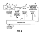
- FIG. 1 is a block diagram of a disk device in accordance with one embodiment of the present invention.
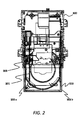
- FIG. 2 is a schematic top plan view of the disk device illustrated in FIG. 1 ;
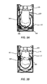
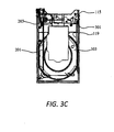
- FIG. 3A is a schematic top plan view of the disk device illustrating a closed state of a disk tray of the disk device
- FIG. 3B is a schematic top plan view of the disk device illustrating an unloading state of the disk tray of the disk device
- FIG. 3C is a schematic top plan view of the disk device illustrating an open state of the disk tray of the disk device
- FIG. 4A is a partial top plan view of the disk device illustrating an off state of a tray-in switch of the disk device
- FIG. 4B is a partial top plan view of the disk device illustrating an on state of the tray-in switch of the disk device;
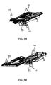
- FIG. 5A is a perspective view of the disk device illustrating a chucking operation
- FIG. 5B is a perspective view of the disk device illustrating an unchucking operation
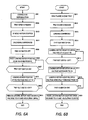
- FIG. 6A is a flowchart illustrating an unloading operation of the disk device illustrated in FIG. 1 ;
- FIG. 6B is a flowchart illustrating a loading operation of the disk device illustrated in FIG. 1 ;
- FIG. 7 is a diagram illustrating a drive voltage of the disk device illustrated in FIG. 1 ;
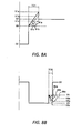
- FIG. 8A is a detail diagram illustrating the drive voltage during an unchucking period.
- FIG. 8B is a detail diagram illustrating the drive voltage during a chucking period.
- FIG. 1 is a block diagram of a disk device.
- the disk device records and reproduces CD's, DVD's, and other such optical disks.
- the disk device includes a disk tray 103, a disk table 105, a chucking pulley (not shown), a loading motor 107, a loading motor drive voltage generating section 109, a spindle motor 111, a chucking section 113, a cam slider 114, a tray-out switch 115, a tray-in switch 117, a rib 119 and a control section 121.
- the disk tray 103 is moved between a close position (e.g., retract position) and an open position (e.g., eject position) by the loading motor 107.
- An optical disk 101 is placed on the disk tray 103 to load the optical disk 101 within the disk device and unload the optical disk 101 from the disk device.
- the disk table 105 is mounted to the spindle motor 111.
- the disk table 105 chucks the optical disk 101 between the disk table 105 and the chucking pulley.
- the chucking pulley is suspended from an upper part of the disk table 105.
- the disk table 105 is raised to a chucking position and engaged from below in a center hole of the optical disk 101. Then, the optical disk 101 is raised above the disk tray 103, at which point the optical disk 101 is magnetically chucked between the disk table 105 and the chucking pulley.
- the loading motor 107 retracts and extracts (e.g., ejects) the disk tray 103. Specifically, the loading motor 107 moves the disk tray 103 between an open position (e.g., eject position) and a close position (e.g., retract position).
- the loading motor drive voltage generating section 109 generates a drive voltage to drive the loading motor 107.
- the spindle motor 111 rotates the optical disk 101 together with the disk table 105.
- the chucking section 113 supports the spindle motor 111 and the disk table 105. The chucking section 113 is moved by the loading motor 107 between a chucking position and an unchucking position.
- the chucking section 113 grips and fixes the optical disk 101 via the disk table 105 when the chucking section 113 is located at the chucking position.
- the cam slider 114 is engaged to a part of the chucking section 113 to raise and lower the chucking section 113 together with the disk table 105 and the spindle motor 111. Specifically, the cam slider 114 raises the chucking section 113 to chuck the optical disk 101 and lowers the chucking section 113 to unchuck the optical disk 101.
- the tray-out switch 115 detects whether or not the disk tray 103 is being loaded or unloaded. Specifically, the tray-out switch 115 detects whether or not the disk tray 103 is located at a predetermined range between the open position and the close position.
- the tray-out switch 115 is turned on when the disk tray 103 is located at the predetermined range between the open position and the close position.
- the tray-out switch 115 is turned off during a certain period after an ejection (retraction) of the disk tray 103 is commenced from the close position (open position), and during a certain period before the ejection (retraction) of the disk tray 103 is complete.
- the tray-in switch 117 detects whether or not the disk tray 103 is located at the close position.
- the rib 119 is provided to the disk tray 103 along a side edge of the disk tray 103 parallel to a direction from the close position to the open position to switch the tray-out switch 115 on and off.
- the control section 121 controls each of the sections of the disk device.
- the control section 121 receives tray open and close commands sent from a remote control 123 to open and close the disk tray 103.
- the loading operation is an operation that retracts the disk tray into the disk device.
- the unloading operation is an operation that ejects the disk tray from the disk device.
- the unloading operation will be described.
- a command to halt a rotation of the spindle motor 111 is sent from the control section 121 in order to stop the rotating of the optical disk 101.
- the spindle motor 111 is stopped.
- the control section 121 sends the loading motor drive voltage generating section 109 a command to generate a positive drive voltage for the unloading operation.
- the positive drive voltage is then applied from the loading motor drive voltage generating section 109 to the loading motor 107 so that a torque of the loading motor 107 gradually increases.
- the loading motor drive voltage generating section 109 generates the positive drive voltage so that the positive drive voltage gradually increases.
- the disk tray 103 commences the unloading operation.
- the cam slider 114 that was pressing on the tray-in switch 117 separates from the tray-in switch 117.
- the tray-in switch 117 is switched off.
- an unchucking operation of the optical disk 101 to unchuck the optical disk 101 is commenced by the chucking section 113.
- the tray-out switch 115 is then switched on by the rib 119 provided to the disk tray 103. Specifically, a front end of the rib 119 pushes the tray-out switch 115. By the time when the tray-out switch 115 is switched on, the unchucking operation is complete. Once the unchucking operation is complete, a first predetermined positive drive voltage V2 (see FIG. 7 ) is applied to the loading motor 107 to unload the disk tray 103 so that the torque of the loading motor 107 is maintained at a predetermined value (e.g., third predetermined value). Then, the rib 119 provided to the disk tray 103 comes up to a rear end. As a result, the tray-out switch 115 is switched off. When the tray-out switch 115 is switched off, the loading motor drive voltage generating section 109 reduce the first predetermined positive drive voltage V2 to 0V to complete the unloading operation.
- V2 see FIG. 7
- the tray close command is sent from the remote control 123 to the control section 121.
- a command to generate a negative drive voltage is sent from the control section 121 to the loading motor drive voltage generating section 109.
- the loading motor drive voltage generating section 109 generates a second predetermined negative drive voltage V3 (see FIG. 7 ) applied to the loading motor 107 to load the disk tray 103 so that the torque of the loading motor 107 is maintained at a predetermined value (e.g., first predetermined value).
- a predetermined value e.g., first predetermined value
- the second predetermined negative drive voltage V3 is applied to the loading motor 107 until the tray-out switch 115 is switched off by the front end of the rib 119 after the tray-out switch 115 is switched on by the rear end of the rib 119.
- the procedures moves to a chucking operation in which the optical disk 101 is clamped (e.g., chucked).
- the second predetermined negative drive voltage V3 that was being applied at a specific level is raised slightly so that the torque of the loading motor 107 is lowered to a predetermined value (e.g., second predetermined value). Then, the negative drive voltage is gradually lowered again so that a torque of the loading motor 107 gradually increases.
- the disk tray 103 is moved to the close position, and the cam slider 114 switches on the tray-in switch 117.
- the control section 121 halts the command to the loading motor drive voltage generating section 109.
- the negative drive voltage applied to the loading motor 107 drops to zero.
- the disk device further includes a loader unit 200.
- FIG. 2 is a top plan view of an intermediate state between the open and close positions of the disk tray 103.
- Optical and electrical components for reproducing the optical disk 101 are installed on the loader unit 200.
- the loader unit 200 retractably and extractably supports the disk tray 103.
- the loader unit 200 supports the chucking section 113.
- the disk tray 103 includes guide rails 202a and 202b provided to both left and right side edges of the disk tray 103 to guide the movement of the disk tray 103 with respect to the loader unit 200.
- a drive force from the loading motor 107 are transmitted to the disk tray 103 via a tray gear 203 linked to the loading motor 107 and a rack 201 provided to a left side potion of the disk tray 103 that meshes with the tray gear 203.
- FIG. 3A shows the close position of the disk tray 103.
- the tray-out switch 115 is located at a right side with respect to the disk tray 103.
- the rib 119 is not extended to a front end of the disk tray 103.
- the tray-out switch 115 is not pressed (e.g., is released) by the rib 119, and the tray-out switch 115 is in an off state.
- the tray gear 203 is rotated by the drive force from the loading motor 107.
- the disk tray 103 is extracted by the rack 201 as shown in FIG. 3B .
- the rib 119 provided to the disk tray 103 presses against a lever switch 301, and the lever switch 301 presses against the tray-out switch 115.
- the tray-out switch 115 turns in an on state.
- the unloading operation continues until the disk tray 103 is completely extracted (in the open position) as shown in FIG. 3C .
- the rib 119 is not extended to a rear end of the disk tray 103.
- the tray-out switch 115 turns in the off state.
- FIGS. 4A and 4B The switching operation of the tray-in switch 117 will be described through reference to FIGS. 4A and 4B .
- the tray-in switch 117 is pressed by a cam slider 114. Then, the tray-in switch 117 turns in an on state.
- FIG. 4B shows a state in which the disk tray 103 has been unloaded.
- the cam slider 114 moves to the left with respect to the tray-in switch 117. As a result, the cam slider 114 no longer presses on the tray-in switch 117. Then, the tray-in switch 117 turns in an off state.
- FIG. 5A shows a state in which the disk tray 103 is located at the close position and the chucking operation is complete.
- the cam slider 114 has moved to the right end with respect to the disk tray 103, and the cam slider 114 lifts up the disk table 105.
- the optical disk 101 is clamped by the disk table 105 and lifted up to a position where the optical disk 101 can be rotated.
- FIG. 5B shows a state in which the disk tray 103 is located at the open position and the unchucking operation is complete.
- the cam slider 114 has moved to the left end with respect to the disk tray 103, and the cam slider 114 pushes the disk table 105 down to a position where the disk table 105 does not interfere with the unloading operation of the disk tray 103.
- FIGS. 6A, 6B and 7 A series of control of the loading and unloading operations will be described through reference to FIGS. 6A, 6B and 7 .
- step S601 the unloading operation performed during disk reproduction (step S601) will be described.
- the tray open command is received (step S602)
- the spindle motor 111 is stopped (step S603) by the command from the control section 121.
- the unloading operation is commenced (step S604)
- the tray-in switch 117 is switched off (step S605).
- the positive drive voltage is raised gradually from a first initial voltage V0 as shown in FIG. 7 , with the upper limit target value being a loading motor permissible positive voltage Vmax (step S606).
- the increase of the positive drive voltage is continued until the tray-out switch 115 is switched on (step S607).
- a period TC1 from when the tray-in switch 117 is switched off until the tray-out switch 115 is switched on is a period of the unchucking operation.
- step S610 when the tray-out switch 115 is off, the positive drive voltage is reduced to 0 V (step S610) and the unloading operation is complete.
- a period TL1 from when the tray-in switch 117 is switched off and the tray-out switch 115 is switched on, until the tray-out switch 115 is switched off the next time is a period of the unloading operation.
- step S613 When the optical disk 101 is placed in the disk tray 103 located at the open position (step S611) and the tray close command is received (step S612), the loading operation is commenced (step S613) and the second predetermined negative drive voltage V3 is applied to the loading motor 107.
- step S614 When the tray-out switch 115 is switched on (step S614), the negative drive voltage is held to the second predetermined voltage V3 (step S615). Then, the control section 121 monitors whether or not the tray-out switch 115 is switched off (step S616). When the tray-out switch 115 has been switched off, the negative drive voltage is raised slightly and set to a second initial voltage V4 (step S617).
- the negative drive voltage is then gradually reduced using the loading motor permissible negative voltage -Vmax as a lower limit target value, and the chucking operation is commenced (step S618).
- the reason for raising the negative drive voltage to the second initial voltage V4 from the second predetermined negative drive voltage V3 is that if the chucking operation is commenced with the second predetermined negative drive voltage V3, then the torque of the loading motor 107 will be too high for the chucking operation, and noise generated during the chucking operation will be too high. Therefore, the negative drive voltage is raised to the second initial voltage V4 to lower the torque.
- the control section 121 monitors whether or not the tray-in switch 117 is on (step S619).
- the negative drive voltage is reduced from the second initial voltage V4 until the control section 121 monitors that the tray-in switch 117 is switched on. Once the tray-in switch 117 is on, the negative drive voltage V5 at this time is raised to 0 V, and the loading operation is complete with the negative drive voltage being held at 0 V.
- a period TL2 from when the tray-out switch 115 is switched on (or when the tray close command is received) and then the tray-in switch 117 is switched on is the loading period.
- a period TC2 from when the tray-out switch 115 is switched offuntil the tray-in switch 117 is switched on is the chucking period.
- FIG. 8A shows a detail wave form of the positive drive voltage during the unchucking period TC1.
- the positive drive voltages V1a, V1b and V1c are voltages reached when the tray-out switch 115 is switched on if the first initial voltage V0 at the start of the unchucking operation is raised at different rates, respectively.
- the rise angles are termed ⁇ 1a, ⁇ 1b and ⁇ 1c, respectively. If the rise angle of the positive drive voltage is increased (as with ⁇ 1a), then the torque is also high in the unchucking operation. Thus, even if the unchucking period TC1 is shortened, it will still be possible to complete the unchucking operation reliably within the unchucking period TC1. However, since the torque is higher, the unchucking operation will tend to be noisier.
- FIG. 8B shows a detail wave form of the negative drive voltage during the chucking period TC2.
- the negative drive voltages V5a, V5b and V5c are voltages reached when the tray-in switch 117 is switched on if the second initial voltage V4 at the start of the chucking operation is reduced at different rates, respectively.
- the fall angles are termed 95a, ⁇ 5b and ⁇ 5c, respectively. If the fall angle of the negative drive voltage is increased (as with ⁇ 5b), then the torque is also high in the chucking operation. Thus, even if the chucking period TC2 is shortened, it will still be possible to complete the chucking operation reliably within the chucking period TC2. However, since the torque is higher, the chucking operation will tend to be noisier.
- the rise angle of the positive drive voltage during the unloading operation and the fall angle of the negative drive voltage during the chucking operation can be set after taking into account speed and noise of the chucking and unchucking operations.
- the design will preferably take into account the balance between operating speed as operation compensation and quietness as operation quality, in order to compensate the variation in load generated by variance of components of the device, or in the loading operation load originally had by the drive device.
- the drive voltage during the chucking and unchucking operations is gradually varied.
- the voltage change is continued from the start until the completion of the chucking and unchucking operations that are detected by the tray-in switch 117 and tray-out switch 115.
- the chucking and unchucking operations can be carried out slowly, which reduces the operating noise.
- the chucking operation is stably complete even if the high loads are encountered when the loading operation and the chucking operation are performed at the same time.
- the chucking and unchucking operations can be carried out reliably. Furthermore, a low-torque loading motor can be employed to the disk device, which lowers the cost, weight, and power consumption of the disk device.
- the lever switch 301 is provided, which makes it possible to carry out the switching operation more reliably by transmitting the pressing force of the rib more reliably to the tray-out switch.
- the present invention can be applied to disk devices that make use of optical disks or other such disk recording medium. More specifically, the present invention is well suited to disk devices that make use of a disk recording medium and having a disk tray loading and unloading function.
Landscapes
- Feeding And Guiding Record Carriers (AREA)
- Holding Or Fastening Of Disk On Rotational Shaft (AREA)
Applications Claiming Priority (1)
| Application Number | Priority Date | Filing Date | Title |
|---|---|---|---|
| JP2007197074A JP4349448B2 (ja) | 2007-07-30 | 2007-07-30 | ディスク記録再生装置 |
Publications (2)
| Publication Number | Publication Date |
|---|---|
| EP2020657A2 true EP2020657A2 (de) | 2009-02-04 |
| EP2020657A3 EP2020657A3 (de) | 2011-08-17 |
Family
ID=39869994
Family Applications (1)
| Application Number | Title | Priority Date | Filing Date |
|---|---|---|---|
| EP08013538A Withdrawn EP2020657A3 (de) | 2007-07-30 | 2008-07-28 | Plattenvorrichtung |
Country Status (3)
| Country | Link |
|---|---|
| US (1) | US8060894B2 (de) |
| EP (1) | EP2020657A3 (de) |
| JP (1) | JP4349448B2 (de) |
Families Citing this family (4)
| Publication number | Priority date | Publication date | Assignee | Title |
|---|---|---|---|---|
| JP4349448B2 (ja) * | 2007-07-30 | 2009-10-21 | 船井電機株式会社 | ディスク記録再生装置 |
| JP5426893B2 (ja) * | 2009-02-09 | 2014-02-26 | 船井電機株式会社 | ディスク装置 |
| KR101336288B1 (ko) * | 2012-07-11 | 2013-12-03 | 도시바삼성스토리지테크놀러지코리아 주식회사 | 디스크 장치 및 그 트레이 구동방법 |
| CN103680540A (zh) * | 2012-08-31 | 2014-03-26 | 联发科技(新加坡)私人有限公司 | 光盘播放机及其进仓出仓控制方法 |
Citations (2)
| Publication number | Priority date | Publication date | Assignee | Title |
|---|---|---|---|---|
| JP2000306308A (ja) | 1999-04-16 | 2000-11-02 | Sony Corp | ディスク装置 |
| JP2007197074A (ja) | 2006-01-30 | 2007-08-09 | Fujifilm Corp | カートリッジ収納ケース |
Family Cites Families (16)
| Publication number | Priority date | Publication date | Assignee | Title |
|---|---|---|---|---|
| US5473593A (en) * | 1994-01-06 | 1995-12-05 | International Business Machines Corporation | Compact disk transport tray moved by a disk reading mechanism |
| JP3728816B2 (ja) * | 1996-07-26 | 2005-12-21 | ソニー株式会社 | ディスク装置 |
| JPH10106111A (ja) * | 1996-09-27 | 1998-04-24 | Mitsumi Electric Co Ltd | ディスク装置及びディスク装置におけるローディングモータの駆動方法 |
| EP1174872B1 (de) * | 2000-07-21 | 2005-03-16 | Sony Corporation | Plattenantriebsgerät |
| KR100942994B1 (ko) * | 2002-01-10 | 2010-02-17 | 파나소닉 주식회사 | 디스크장치 |
| JP3969288B2 (ja) * | 2002-11-19 | 2007-09-05 | ティアック株式会社 | 記録媒体駆動装置 |
| JP4006594B2 (ja) * | 2003-06-18 | 2007-11-14 | セイコーエプソン株式会社 | トレイ送り制御装置、記録装置、液体噴射装置 |
| US7386866B2 (en) * | 2003-06-30 | 2008-06-10 | Koninklijke Philips Electronics N.V. | Disk drive with improved tray control |
| US7287263B2 (en) * | 2003-08-29 | 2007-10-23 | Alpine Electronics, Inc. | Disc apparatus |
| TW200529177A (en) * | 2004-02-25 | 2005-09-01 | Lite On It Corp | Optical disc drive capable of adjusting tray-in and tray-out speed |
| JP4702005B2 (ja) * | 2005-11-18 | 2011-06-15 | 船井電機株式会社 | 光ディスク装置 |
| CN101004931A (zh) * | 2006-01-18 | 2007-07-25 | 鸿富锦精密工业(深圳)有限公司 | 光碟机的托盘进仓/出仓装置 |
| KR100712335B1 (ko) | 2006-02-09 | 2007-05-02 | 주식회사 히타치엘지 데이터 스토리지 코리아 | 광디스크 장치 |
| JP4882547B2 (ja) * | 2006-06-29 | 2012-02-22 | ティアック株式会社 | ディスク装置 |
| KR20090094030A (ko) * | 2006-12-14 | 2009-09-02 | 코닌클리케 필립스 일렉트로닉스 엔.브이. | 디스크 드라이브와 트레이 제어 기구 |
| JP4349448B2 (ja) * | 2007-07-30 | 2009-10-21 | 船井電機株式会社 | ディスク記録再生装置 |
-
2007
- 2007-07-30 JP JP2007197074A patent/JP4349448B2/ja not_active Expired - Fee Related
-
2008
- 2008-07-24 US US12/178,737 patent/US8060894B2/en not_active Expired - Fee Related
- 2008-07-28 EP EP08013538A patent/EP2020657A3/de not_active Withdrawn
Patent Citations (2)
| Publication number | Priority date | Publication date | Assignee | Title |
|---|---|---|---|---|
| JP2000306308A (ja) | 1999-04-16 | 2000-11-02 | Sony Corp | ディスク装置 |
| JP2007197074A (ja) | 2006-01-30 | 2007-08-09 | Fujifilm Corp | カートリッジ収納ケース |
Also Published As
| Publication number | Publication date |
|---|---|
| JP4349448B2 (ja) | 2009-10-21 |
| US8060894B2 (en) | 2011-11-15 |
| EP2020657A3 (de) | 2011-08-17 |
| JP2009032350A (ja) | 2009-02-12 |
| US20090037942A1 (en) | 2009-02-05 |
Similar Documents
| Publication | Publication Date | Title |
|---|---|---|
| US7974159B2 (en) | Tray controlling method using firmware for detecting different inclined position | |
| EP2020657A2 (de) | Plattenvorrichtung | |
| US7003785B2 (en) | Recording medium driving device | |
| US20010038595A1 (en) | Information recording medium reproducing apparatus and method | |
| JP2009037710A (ja) | ディスクドライブ装置 | |
| CN100429708C (zh) | 盘片驱动装置以及盘片驱动装置的驱动控制方法 | |
| CN1815598B (zh) | 光盘装置 | |
| JPH11144354A (ja) | 光ディスクプレーヤ | |
| US7676819B2 (en) | Disk conveying apparatus | |
| JP4529800B2 (ja) | ディスクドライブ装置 | |
| JP4487860B2 (ja) | ディスクドライブ装置 | |
| CN100426401C (zh) | 用于再现装置的盘托架机构 | |
| WO2005093741A1 (ja) | ディスク装置 | |
| JP4230155B2 (ja) | ディスクローディング装置 | |
| JPH0991815A (ja) | ディスク再生装置 | |
| JP4329663B2 (ja) | ディスクドライブ装置 | |
| JP2007122767A (ja) | 光ディスク装置及び対物レンズの退避移動方法 | |
| JP2008159090A (ja) | 記録媒体駆動装置及び電子機器 | |
| WO2006016656A1 (ja) | ディスクドライブ装置 | |
| JP2006018995A (ja) | ディスクドライブ装置 | |
| JP2008159092A (ja) | 搬送機構、記録媒体駆動装置及び電子機器 | |
| JP2008159093A (ja) | 記録媒体駆動装置及び電子機器 | |
| JP2008159091A (ja) | 記録媒体駆動装置及び電子機器 | |
| JP2007004912A (ja) | ディスク装置のディスクローディング方法 | |
| JPH11213582A (ja) | 光磁気ディスク装置 |
Legal Events
| Date | Code | Title | Description |
|---|---|---|---|
| PUAI | Public reference made under article 153(3) epc to a published international application that has entered the european phase |
Free format text: ORIGINAL CODE: 0009012 |
|
| AK | Designated contracting states |
Kind code of ref document: A2 Designated state(s): AT BE BG CH CY CZ DE DK EE ES FI FR GB GR HR HU IE IS IT LI LT LU LV MC MT NL NO PL PT RO SE SI SK TR |
|
| AX | Request for extension of the european patent |
Extension state: AL BA MK RS |
|
| PUAL | Search report despatched |
Free format text: ORIGINAL CODE: 0009013 |
|
| AK | Designated contracting states |
Kind code of ref document: A3 Designated state(s): AT BE BG CH CY CZ DE DK EE ES FI FR GB GR HR HU IE IS IT LI LT LU LV MC MT NL NO PL PT RO SE SI SK TR |
|
| AX | Request for extension of the european patent |
Extension state: AL BA MK RS |
|
| RIC1 | Information provided on ipc code assigned before grant |
Ipc: G11B 17/028 20060101ALI20110714BHEP Ipc: G11B 17/056 20060101AFI20110714BHEP |
|
| 17P | Request for examination filed |
Effective date: 20120208 |
|
| AKX | Designation fees paid |
Designated state(s): DE FR GB |
|
| GRAP | Despatch of communication of intention to grant a patent |
Free format text: ORIGINAL CODE: EPIDOSNIGR1 |
|
| INTG | Intention to grant announced |
Effective date: 20130507 |
|
| STAA | Information on the status of an ep patent application or granted ep patent |
Free format text: STATUS: THE APPLICATION IS DEEMED TO BE WITHDRAWN |
|
| 18D | Application deemed to be withdrawn |
Effective date: 20130918 |