EP2020001B1 - Dispositif de diagnostic de processus dédié - Google Patents
Dispositif de diagnostic de processus dédié Download PDFInfo
- Publication number
- EP2020001B1 EP2020001B1 EP07809165.9A EP07809165A EP2020001B1 EP 2020001 B1 EP2020001 B1 EP 2020001B1 EP 07809165 A EP07809165 A EP 07809165A EP 2020001 B1 EP2020001 B1 EP 2020001B1
- Authority
- EP
- European Patent Office
- Prior art keywords
- diagnostic
- industrial
- program instructions
- control
- control loop
- Prior art date
- Legal status (The legal status is an assumption and is not a legal conclusion. Google has not performed a legal analysis and makes no representation as to the accuracy of the status listed.)
- Active
Links
Images

Classifications
-
- G—PHYSICS
- G01—MEASURING; TESTING
- G01F—MEASURING VOLUME, VOLUME FLOW, MASS FLOW OR LIQUID LEVEL; METERING BY VOLUME
- G01F1/00—Measuring the volume flow or mass flow of fluid or fluent solid material wherein the fluid passes through a meter in a continuous flow
- G01F1/05—Measuring the volume flow or mass flow of fluid or fluent solid material wherein the fluid passes through a meter in a continuous flow by using mechanical effects
- G01F1/34—Measuring the volume flow or mass flow of fluid or fluent solid material wherein the fluid passes through a meter in a continuous flow by using mechanical effects by measuring pressure or differential pressure
- G01F1/50—Correcting or compensating means
-
- G—PHYSICS
- G01—MEASURING; TESTING
- G01F—MEASURING VOLUME, VOLUME FLOW, MASS FLOW OR LIQUID LEVEL; METERING BY VOLUME
- G01F15/00—Details of, or accessories for, apparatus of groups G01F1/00 - G01F13/00 insofar as such details or appliances are not adapted to particular types of such apparatus
-
- G—PHYSICS
- G05—CONTROLLING; REGULATING
- G05B—CONTROL OR REGULATING SYSTEMS IN GENERAL; FUNCTIONAL ELEMENTS OF SUCH SYSTEMS; MONITORING OR TESTING ARRANGEMENTS FOR SUCH SYSTEMS OR ELEMENTS
- G05B19/00—Programme-control systems
- G05B19/02—Programme-control systems electric
- G05B19/04—Programme control other than numerical control, i.e. in sequence controllers or logic controllers
- G05B19/042—Programme control other than numerical control, i.e. in sequence controllers or logic controllers using digital processors
- G05B19/0428—Safety, monitoring
-
- G—PHYSICS
- G08—SIGNALLING
- G08C—TRANSMISSION SYSTEMS FOR MEASURED VALUES, CONTROL OR SIMILAR SIGNALS
- G08C19/00—Electric signal transmission systems
- G08C19/02—Electric signal transmission systems in which the signal transmitted is magnitude of current or voltage
-
- G—PHYSICS
- G05—CONTROLLING; REGULATING
- G05B—CONTROL OR REGULATING SYSTEMS IN GENERAL; FUNCTIONAL ELEMENTS OF SUCH SYSTEMS; MONITORING OR TESTING ARRANGEMENTS FOR SUCH SYSTEMS OR ELEMENTS
- G05B2219/00—Program-control systems
- G05B2219/20—Pc systems
- G05B2219/24—Pc safety
- G05B2219/24033—Failure, fault detection and isolation
Definitions
- the present invention relates to process control systems of the type used to monitor and/or control operation of industrial processes. More specifically, the present invention relates to diagnostics of such process control systems.
- Field devices are used in the process control industry to remotely control or sense a process variable.
- a process variable may be transmitted to a control room by a transmitter for use in controlling the process or for providing information about process operation to a controller.
- information related to pressure of process fluid may be transmitted to a control room and used to control the process, such as oil refining.
- the present invention provides a field mountable dedicated process diagnostic device according to claim 1, and a method of diagnosing operation of an industrial control or monitoring system of an industrial process according to claim 11.
- a field mountable dedicated process diagnostic device and method for use in diagnosing operation of an industrial control or monitoring system is provided.
- An input receives at least one process signal related to operation of the industrial process.
- a memory contains diagnostic program instructions configured to implement a diagnostic algorithm using the at least one process signal.
- the diagnostic algorithm may be specific to the industrial process in which the device or method is implemented.
- a microcontroller performs the diagnostic program instructions and responsively diagnoses operation of the process based upon the at least one process signal.
- the present invention provides a dedicated process diagnostic device and method for use in diagnosing operation of an industrial process control or monitoring system.
- the dedicated process diagnostic device does not perform functions other than diagnostics in the process control system.
- the device is not used to measure a process variable used in performing or monitoring process control, and is also not used to control process operation.
- the device in which the device is dedicated to performing diagnostics, its computational abilities can be substantially focused on this activity.
- the device can be configured to comply with requirements for mounting at a remote location in the field including intrinsic safety requirements and other requirements needed for the device to be "field hardened".
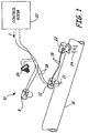
- Figure 1 is a diagram of process control system 10 which includes dedicated field mounted diagnostic device 8.
- the process control system 10 also includes a transmitter 12 and a valve positioner 22 coupled to process pipe 16.
- a sensor 21 is shown generically in Figure 1 and couples to transmitter 12.
- Figure 1 also shows valve positioner 22 coupled to a control element 24 such as a valve.
- a process monitor 26 (illustrated as a hand held device) is also shown coupled to loop 18.
- One typical technique for transmitting information involves controlling the amount of power flowing through a process control loop.
- Current is supplied from a current source in the control room and the transmitter controls the current from its location in the field.
- a 4 mA signal can be used to indicate a zero reading and a 20 mA signal can be used to indicate a full scale reading.
- transmitters have employed digital circuitry which communicates with the control room using a digital signal which is superimposed : onto the analog current signal flowing through the process control loop.
- One example of such a technique is the HART® communication protocol proposed by Rosemount Inc.
- the HART® protocol and other such protocols typically include a set of commands or instructions which can be sent to the transmitter to elicit a desired response, such as transmitter control or interrogation.
- Fieldbus is a communications protocol proposed by the Fieldbus Foundation and is directed to defining a communications layer or protocol for transmitting information on a process control loop.
- the Fieldbus protocol the current flowing through the loop is not used to transmit an analog signal. Instead, all information is digitally transmitted.
- the Fieldbus standard, and a standard known as Profibus allow transmitters to be configured in a multi-drop configuration in which more than one transmitter is connected on the same process control loop.
- Other communication protocols include the MODBUS® protocol and Ethernet. In some configurations, two, three, four or any number of wires can be used to connect to the process device, including non-physical connections such as RF (radio frequency).
- Diagnostic device 8 transmitter 12 and positioner 22 are coupled to a two-wire process control loop 18 which operates in accordance with the Fieldbus, Profibus or HART® standard.
- Two-wire process control loop 18 runs between a location in the field and the control room 20.
- loop 18 can carry a current I which is representative of a sensed process variable.
- the HART® protocol allows a digital signal to be superimposed on the current through loop 18 such that digital information can be sent to or received from transmitter 12.
- loop 18 When operating in accordance with the Fieldbus standard, loop 18 carries digital signals and can be coupled to multiple field devices such as other transmitters. Any number of two wire process control loops 18 can be used and coupled to field mounted devices as appropriate.
- the configurations shown herein are for example purposes only.
- Process variables are typically the primary variables which are being controlled in a process.
- process variable means any variable which describes the condition of the process such as, for example, pressure, flow, temperature, product level, pH, turbidity, vibration, position, motor current, any other characteristic of the process, etc.
- Control signal means any signal (other than a process variable) which is used to control the process.
- control signal means a desired process variable value (i.e. a setpoint) such as a desired temperature, pressure, flow, product level, pH or turbidity, etc., which is adjusted by a controller or used to control the process.
- a control signal means, calibration values, alarms, alarm conditions, the signal which is provided to a control element such as a valve position signal which is provided to a valve actuator, an energy level which is provided to a heating element, a solenoid on/off signal, etc., or any other signal which relates to control of the process.
- a diagnostic signal as used herein includes information related to operation of devices and elements in the process control loop, but does not include process variables or control signals.
- diagnostic signals include valve stem position, applied torque or force, actuator pressure, pressure of a pressurized gas used to actuate a valve, electrical voltage, current, power, resistance, capacitance, inductance, device temperature, stiction, friction, full on and off positions, travel, frequency, amplitude, spectrum and spectral components, stiffness, electric or magnetic field strength, duration, intensity, motion, electric motor back emf, motor current, loop related parameters (such as control loop resistance, voltage, or current), or any other parameter which may be detected or measured in the system.
- process signal means any signal which is related to the process or element in the process such as, for example, a process variable, a control signal or a diagnostic signal.
- Process devices include any device which forms part of or couples to a process control loop and is used in the control or monitoring of a process.
- FIG. 1 is a diagram showing an example of a process control system 10 which includes process piping 16 which carries a process fluid and two wire process control loop 18 carrying loop current I.
- Transmitter 12, controller 22 (which couples to a final control element in the loop such as an actuator, valve, a pump, motor or solenoid), process monitor 26 and control room 20 are all part of process control loop 18.
- loop 18 is shown in one configuration and any appropriate process control loop may be used such as a 4-20 mA loop, 2, 3 or 4 wire loop, multi-drop loop and a loop operating in accordance with the HART®, Fieldbus or other digital or analog communication protocol.
- transmitter 12 senses a process variable such as flow using sensor 21 and transmits the sensed process variable over loop 18.
- the process variable may be received by controller/valve actuator 22, diagnostic device 8, control room equipment 20 and/or process monitor 26.
- Controller 22 is shown coupled to valve 24 and is capable of controlling the process by adjusting valve 24 thereby changing the flow in pipe 16.
- Controller 22 receives a control input over loop 18 from, for example, control room 20 or transmitter 12 and responsively adjusts valve 24.
- controller 22 internally generates the control signal based upon process signals received over loop 18.
- Process devices include, for example, transmitter 12 (such as a 3051S transmitter available from Rosemount Inc.), controller 22, a handheld process monitor 26, diagnostic device 8 and control room 20 shown in Figure 1 .
- Another type of process device is a PC, programmable logic unit (PLC) or other computer coupled to the loop using appropriate I/O circuitry to allow monitoring, managing, and/or transmitting on the loop.
- PLC programmable logic unit
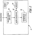
- Figure 2 is a block diagram of field mounted dedicated diagnostic device 8.
- Device 8 is configured to couple to the process control system 10 of Figure 1 and includes a process signal input 40 configured to receive one or more process signals from the process control system 10.
- a microprocessor 42 receives the process signals and is coupled to a memory 44.
- the memory 44 contains diagnostic program instructions configured to implement a diagnostic algorithm in the microprocessor 42.
- the diagnostic algorithm uses at least one: process signal received by input 40 from the process.
- the diagnostic algorithm which is implemented in the microprocessor is specific to the particular process and configuration being monitored. For example, algorithms used to monitor operation of a process which controls level of process fluid in a tank may be different than the algorithm used to diagnose operation of a control system process which controls flow of process fluid through a pipe.
- the microprocessor 42 Based upon the algorithm and this process signal, the microprocessor 42 provides some type of diagnostic output 46.
- the diagnostic output 46 can be an output used only internally by the device 8, or can be an output which is transmitted to a remote location, for example over the process control loop 18 shown in Figure 1 .
- Device 8 also includes a power supply 50 which, in some embodiments, is configured to receive power from the two wire process control loop 18 for completely powering all electrical components within device 8.
- the present invention offers a new class of field mountable process device which is used to monitor process conditions, detect process abnormalities and changes and provide diagnostics related to process operation and optimization.
- Typical process devices do not have the computational ability to support the addition of complex diagnostics. This limitation is due to power constraints, and requirements for field hardening of the device to withstand hazardous locations and harsh environmental conditions.
- the dedicated device provides an operator functionality to monitor process conditions and signatures, trends, changes, upsets or other abnormalities which can be analyzed and used to troubleshoot system operation.
- the diagnostic information can then be communicated to a host system for use as appropriate, including a controlled plant shutdown.
- the dedicated device has access to real time process information.
- equipment located at a remote location such as the control room
- the diagnostic capabilities are limited because the remote equipment has limited access to process signals. For example, control room equipment has limited input/output capabilities, limited scan or update times, and limited bandwidth.
- Field hardening of the device allows operation in hazardous environments or in environments in which the device is subjected to a harsh conditions.
- the device operates using sufficiently low power consumption to allow operation using power completely received from a two wire process control loop.
- other configurations are used such as a four wire configuration.
- the memory 44 can be used to provide additional capabilities such as logging, trending, and analysis.
- the dedicated device 8 can also be used for testing diagnostic algorithms and techniques prior to adding such functionality to other process devices.
- the process signals used by device 8 can be received by monitoring transmissions on the process control loop. However, process signals can also be received through dedicated sensors directly coupled to the diagnostic device 8.
- the diagnostics performed by the device can be based on additional information, for example control information such as a setpoint, valve position, or the like, to perform higher level loop or device specific diagnostics.
- the device 8 can provide multiple types of diagnostic outputs, either individually or together, including annunciations, alarm signals, control signals, etc. Communication with the process device can be through the process control loop using standard communication techniques or can be through other techniques including wireless communications or using web connectivity.
- Figure 3 is a block diagram of an example embodiment of a dedicated field mounted process diagnostic device 100.
- Device 100 generally includes input(s) 102, conversion circuit(s) 104, computational circuitry 106, application specific data 108 and output circuitry 110.
- Input(s) 102 can couple to any number of diagnostic sensors 112A, 112B ... 112N.
- the sensors can be dedicated sensors which are directly coupled to device 100, or can be sensors coupled to device 100 through a databus such as a process control loop.
- the diagnostic variable sensors 112A-112N can measure any variable related to operation of the process or devices associated with the process.
- diagnostic sensors are shown as providing pressure, temperature, flow, vibration or acoustic signals.
- the connection between the diagnostic sensors and the input block 102 of device 100 can be through a databus so that the sensors are located remotely, or through a direct connection.
- the databus can be any type of databus, for example, a two wire process control loop. Further, other types of databuses can be used such as a CAN bus, an SPI bus, etc.
- the conversion circuitry 104 is used as required to convert received process signals into a format suitable for use by computation circuitry 106.
- the computation circuitry 106 is illustrated as providing digital signal processing, fuzzy logic, neural networks or other computations. However, the circuitry can perform a desired form of a diagnostic computation.
- Application data 108 can be stored in a memory and can be set using an LOI (Local Operator Interface) or other technique to provide set application specific constants.
- the data can be downloaded over a process control loop sent using a wireless communication link, configured using a web interface, or through the other techniques.
- Output circuitry 110 is illustrated as including a connection to the control room for providing digital, or analog signals. Examples include Fieldbus, HART®, analog data, digital data, contact closures or the like.
- a wireless communication output can also be provided.
- An optional acoustic transducer 116 is illustrated. The acoustic transducer 116 can be used to obtain additional diagnostic information, for example by applying a acoustic signal to a process component and observing the response through input circuitry 102.
- the diagnostic device 100 is configured for a location in the field near the equipment or process that is being monitored for aberrant activity.
- the device 100 can be connected to existing process variable measurement devices, and/or other sensors that monitor other variables useful for performing a diagnostic function.
- the output of the diagnostic device 100 can be configured as desired.
- Example outputs include a local output to a handheld device such as a wireless or clip-on device.
- a visual indicator can also be provided, for example providing a color coded output with red indicating an alarm condition, yellow indicating a caution condition and green indicating nominal operation.
- the output can also be provided over an Internet connection, or through the connection to the control room.
- a Local Operation Interface (LOI) can also be provided for use in configuring the device and/or for providing a diagnostic output.
- LOI Local Operation Interface
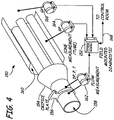
- FIG 4 is a simplified schematic diagram of a heat exchanger system 150 including a dedicated field mounted diagnostic device 152.
- System 150 includes heat exchanger 154 having an orifice plate 156, a primary flow input 158 and a counter flow 160.
- a flow measurement transmitter 162 is shown coupled across the orifice plate 156 and is configured to measure differential pressure, gage or absolute pressure and temperature. The output from transmitter 162 is received by diagnostic device 152. Additionally, transmitters 164 and 166 are illustrated as measuring gauging pressure along heat exchanger system 150.
- Field mounted diagnostic device 152 also monitors the gauge pressure measurement from transmitters 164 and 166.
- a two wire process control loop connection 168 is shown which couples diagnostic device 152 to a remote control room. During operation, the diagnostic device 152 can monitor the various process variables.
- the differential pressure across the flow tubes in the heat exchanger can be monitored by observing the difference between the gauge pressures measured by transmitter 164 and transmitter 166. Given mass flow rate measured by transmitter 162, an expected differential pressure between gauges 164 and 166 can be calculated by diagnostic device 152. If the tubing within heat exchanger 154 becomes clogged, the expected differential pressure measured between transmitters 164 and 166 will deviate from the expected value. This can be used to trigger a diagnostic indication for local output, or transmission to the control room. Typically, the tubes within the heat exchanger 154 do not become plugged at the same rate.
- the gauge pressure measurement transmitters 164 and 166 can be used to measure pressures along the length of the exchanger tubing.
- Transmitters 164 and 166 can also be used to identify tubes that are plugging at a faster rate than others. This allows for maintenance to be correlated with the severity of the plugging. For example, a group of tubes which are completely plugged will cause a pressure drop across the entire heat exchanger tube group and may need immediate cleaning. On the other hand, an even build up among all of the tubing may cause the same pressure drop but may not require immediate attention.
- Figure 4 is one example embodiment and the present invention is applicable to all types of process control systems.
- Other examples include exchangers of all types, reactors, process overflow and leakage detection, cavitation sensing and/or prediction, corrosion monitoring, wear monitoring, identification of process operation which is outside particular limits, or other specialized applications.
- the field mounted diagnostic device provides a co-located, dedicated diagnostic capability to determine whether abnormal conditions in the process exist, and if so, to what extent.
- the device can accept many types of sensor inputs and can be cognizant of information carried on the process control loop, such as setpoint information, to reduce inaccuracies in the diagnostics.
- the device can be configurable through sensor selection and software to accommodate many different types of diagnostic application requirements.
- the device is capable of local access and interrogation due to the co-location with the target system under diagnostic. Local output diagnostics can be used in physical observations of the system by an operator. The device need only monitor sensors and process variables required for the particular system which is being observed.
- the device can provide multiple outputs for viewing alarms and supporting of an appropriate level of detail as desired.
- Similar devices can be used for many different applications through the use of different software configurations.
- the device can be monitored over existing networks including communications through modems or the like.
- the diagnostic device is physically hardened for field mounted applications. In such a configuration, the device should be able to withstand vibrations, caustic chemicals, electrostatic discharges, etc. for a particular installation.
- the output from the device can be in the form of a transmission to a remote location using wired or wireless techniques, a local output, outputs that support virtual web pages or transmission through the Internet, or other types of output.
- Any type of diagnostic technique can be used within the device including fuzzy logic techniques, neural network techniques, rule based techniques or the like.
- the device can also be configured to provide a particular input or stimulus to the process, such as through the application of an acoustic signal. Sensors within the device can monitor the response of components to the applied signal and the response can be used for the diagnostics performed by the device.
- diagnostic sensors are sensors which are dedicated to obtaining diagnostic measurements and are not used in controlling the process.
- program instructions which are performed by the microprocessor have the capability of learning operation of the monitored process by monitoring operation of the process.
Landscapes
- Physics & Mathematics (AREA)
- General Physics & Mathematics (AREA)
- Fluid Mechanics (AREA)
- Engineering & Computer Science (AREA)
- Automation & Control Theory (AREA)
- Testing And Monitoring For Control Systems (AREA)
Claims (15)
- Dispositif de diagnostic de processus dédié pouvant être monté sur site (8 ; 100 ; 152) pouvant être couplé à une boucle de commande de processus à deux fils (18 ; 168) et configuré pour être complètement alimenté avec une alimentation reçue sur la boucle de commande de processus à deux fils, et dédié à un diagnostic du fonctionnement d'un système de commande ou de surveillance industriel d'un processus industriel de telle sorte que le dispositif n'est pas configuré pour exécuter des fonctions autres que des diagnostics, à savoir le dispositif n'est pas configuré pour mesurer une variable de processus utilisée pour effectuer ou surveiller une commande de processus ou pour commander un fonctionnement de processus, le dispositif comprenant :une entrée (40 ; 102) configurée pour recevoir au moins un signal de processus lié à un fonctionnement du processus industriel à partir d'un capteur de diagnostic ;une mémoire (44) contenant des instructions de programme de diagnostic configurées pour mettre en œuvre un algorithme de diagnostic utilisant le au moins un signal de processus et dans lequel l'algorithme de diagnostic est sélectionné parmi une pluralité d'algorithmes de diagnostic de manière à être spécifique au processus industriel ; etune microcommande (42 ; 106) configurée pour exécuter les instructions de programme de diagnostic et diagnostiquer en réponse un fonctionnement du processus industriel sur la base du au moins un signal de processus.
- Dispositif selon la revendication 1, dans lequel le dispositif de diagnostic de processus dédié est configuré pour que le signal de processus soit reçu d'une boucle de commande de processus à deux fils.
- Dispositif selon la revendication 2, dans lequel la boucle de commande de processus comprend une boucle de courant de 4 à 20 mA.
- Dispositif selon la revendication 1, comprenant un circuit de conversion configuré pour convertir le signal de traitement vers un format compatible avec la microcommande.
- Dispositif selon la revendication 1, dans lequel le processus industriel comprend un processus d'échangeur de chaleur (154) et les instructions de programme de diagnostic sont spécifiques au processus d'échangeur de chaleur.
- Dispositif selon la revendication 1, dans lequel les instructions de programme de diagnostic sont configurées pour apprendre le fonctionnement du processus.
- Dispositif selon la revendication 1, dans lequel le capteur de diagnostic comprend un capteur de vibrations et dans lequel l'algorithme de diagnostic est spécifique au diagnostic de fonctionnement d'un échangeur de chaleur.
- Dispositif selon la revendication 1, dans lequel les instructions de programme de diagnostic sont configurées via une entrée de configuration.
- Dispositif selon la revendication 8, dans lequel l'entrée de configuration comprend une interface d'opérateur locale ou une entrée sans fil.
- Dispositif selon la revendication 8 configuré pour recevoir l'entrée de configuration via la boucle de commande de processus.
- Procédé de diagnostic du fonctionnement d'un système de commande ou de surveillance industriel d'un processus industriel effectué dans un dispositif de diagnostic de processus dédié pouvant être monté sur site (8 ; 100 ; 152) couplé à une boucle de commande de processus à deux fils (18 ; 168) et entièrement alimenté avec une alimentation reçue sur la boucle de commande de processus à deux fils, et dédié au diagnostic du fonctionnement d'un système de commande ou de surveillance industriel d'un processus industriel de telle sorte que l'appareil n'est pas configuré pour effectuer des fonctions autres que des diagnostics, à savoir que l'appareil n'est pas configuré pour mesurer une variable de processus utilisé pour effectuer ou surveiller une commande de processus ou pour commander le fonctionnement d'un processus, le procédé comprenant les étapes consistant à :sélectionner des instructions de programme de diagnostic pour mettre en œuvre un algorithme de diagnostic à partir d'une pluralité d'algorithmes de diagnostic afin qu'il soit spécifique au processus industriel ;configurer le dispositif de diagnostic de processus pour contenir les instructions de programme de diagnostic ;monter le dispositif de diagnostic de processus dans un site du processus industriel ;recevoir au moins un signal de processus lié au fonctionnement du processus industriel à partir d'un dispositif de processus distant (12, 21, 22 ; 112A, 112B, ..., 112N ; 162, 164, 166) ;récupérer les instructions de programme de diagnostic qui sont configurées pour mettre en œuvre l'algorithme de diagnostic sélectionné en utilisant au moins un signal de processus ;diagnostiquer le fonctionnement du processus industriel sur la base des instructions de programme récupérées et du au moins un signal de processus ; etalimenter complètement le dispositif de diagnostic de processus avec une alimentation reçue d'une boucle de commande de processus à deux fils (18 ; 108).
- Procédé selon la revendication 11, dans lequel la boucle de commande de processus à deux fils comprend une boucle de courant de 4 à 20 mA.
- Procédé selon la revendication 11, comprenant la conversion du signal de traitement vers un format compatible avec une microcommande (42 ; 106).
- Procédé selon la revendication 11, dans lequel le processus industriel comprend un processus d'échangeur de chaleur (154) et les instructions de programme de diagnostic sont spécifiques au processus d'échangeur de chaleur.
- Procédé selon la revendication 11, dans lequel les instructions de programme de diagnostic sont configurées pour apprendre le fonctionnement du processus.
Applications Claiming Priority (2)
| Application Number | Priority Date | Filing Date | Title |
|---|---|---|---|
| US11/440,582 US7630861B2 (en) | 1996-03-28 | 2006-05-25 | Dedicated process diagnostic device |
| PCT/US2007/012317 WO2007139843A2 (fr) | 2006-05-25 | 2007-05-23 | Dispositif de diagnostic de processus dédié |
Publications (2)
| Publication Number | Publication Date |
|---|---|
| EP2020001A2 EP2020001A2 (fr) | 2009-02-04 |
| EP2020001B1 true EP2020001B1 (fr) | 2020-03-25 |
Family
ID=38695566
Family Applications (1)
| Application Number | Title | Priority Date | Filing Date |
|---|---|---|---|
| EP07809165.9A Active EP2020001B1 (fr) | 2006-05-25 | 2007-05-23 | Dispositif de diagnostic de processus dédié |
Country Status (5)
| Country | Link |
|---|---|
| US (1) | US7630861B2 (fr) |
| EP (1) | EP2020001B1 (fr) |
| JP (1) | JP5883551B2 (fr) |
| CN (1) | CN101454813B (fr) |
| WO (1) | WO2007139843A2 (fr) |
Families Citing this family (39)
| Publication number | Priority date | Publication date | Assignee | Title |
|---|---|---|---|---|
| US7623932B2 (en) * | 1996-03-28 | 2009-11-24 | Fisher-Rosemount Systems, Inc. | Rule set for root cause diagnostics |
| US8290721B2 (en) | 1996-03-28 | 2012-10-16 | Rosemount Inc. | Flow measurement diagnostics |
| US7035773B2 (en) * | 2002-03-06 | 2006-04-25 | Fisher-Rosemount Systems, Inc. | Appendable system and devices for data acquisition, analysis and control |
| US7627441B2 (en) * | 2003-09-30 | 2009-12-01 | Rosemount Inc. | Process device with vibration based diagnostics |
| US7627455B2 (en) * | 2004-08-31 | 2009-12-01 | Watlow Electric Manufacturing Company | Distributed diagnostic operations system |
| US8112565B2 (en) | 2005-06-08 | 2012-02-07 | Fisher-Rosemount Systems, Inc. | Multi-protocol field device interface with automatic bus detection |
| US20070068225A1 (en) * | 2005-09-29 | 2007-03-29 | Brown Gregory C | Leak detector for process valve |
| US7953501B2 (en) * | 2006-09-25 | 2011-05-31 | Fisher-Rosemount Systems, Inc. | Industrial process control loop monitor |
| US8788070B2 (en) | 2006-09-26 | 2014-07-22 | Rosemount Inc. | Automatic field device service adviser |
| EP2074385B2 (fr) | 2006-09-29 | 2022-07-06 | Rosemount Inc. | Débitmètre électromagnétique équipé d'un moyen de vérification |
| US8898036B2 (en) * | 2007-08-06 | 2014-11-25 | Rosemount Inc. | Process variable transmitter with acceleration sensor |
| US7590511B2 (en) * | 2007-09-25 | 2009-09-15 | Rosemount Inc. | Field device for digital process control loop diagnostics |
| EP2223071B1 (fr) * | 2007-11-29 | 2014-01-08 | Rosemount, Inc. | Transmetteur de pression de fluide de traitement avec détection de transitoire de pression |
| US8264373B2 (en) * | 2008-01-04 | 2012-09-11 | Rosemount Tank Radar Ab | Gauging system having wireless capability |
| US9182256B2 (en) * | 2009-07-09 | 2015-11-10 | Rosemount Inc. | Process variable transmitter with two-wire process control loop diagnostics |
| US8787202B2 (en) * | 2010-06-22 | 2014-07-22 | George W. Kuriyan | Method and system using wireless packet data networks architecture for remote process control and process monitoring applications |
| US8449181B2 (en) * | 2010-08-26 | 2013-05-28 | Rosemount Inc. | Process fluid temperature measurement |
| US8448525B2 (en) * | 2011-03-03 | 2013-05-28 | Rosemount Inc. | Differential pressure based flow measurement |
| US9207670B2 (en) | 2011-03-21 | 2015-12-08 | Rosemount Inc. | Degrading sensor detection implemented within a transmitter |
| CN102288849B (zh) * | 2011-06-29 | 2013-10-02 | 上海工业自动化仪表研究院 | 一种hart回路故障诊断仪及诊断方法 |
| US8706448B2 (en) * | 2011-07-07 | 2014-04-22 | Rosemount Inc. | Wireless field device with removable power source |
| US9020768B2 (en) | 2011-08-16 | 2015-04-28 | Rosemount Inc. | Two-wire process control loop current diagnostics |
| US20140143607A1 (en) * | 2012-02-10 | 2014-05-22 | Phoenix Contact Development & Manufacturing, Inc. | Dedicated Network Diagnostics Module for a Process Network |
| JP5574191B2 (ja) * | 2012-06-26 | 2014-08-20 | 横河電機株式会社 | 電磁流量計動作検証システム |
| US9052240B2 (en) | 2012-06-29 | 2015-06-09 | Rosemount Inc. | Industrial process temperature transmitter with sensor stress diagnostics |
| US9255649B2 (en) * | 2012-08-07 | 2016-02-09 | Fisher Controls International, Llc | Apparatus for fluid control device leak detection |
| US9602122B2 (en) | 2012-09-28 | 2017-03-21 | Rosemount Inc. | Process variable measurement noise diagnostic |
| US9222844B2 (en) * | 2013-02-25 | 2015-12-29 | Rosemount Inc. | Process temperature transmitter with improved sensor diagnostics |
| DE202013101455U1 (de) * | 2013-04-05 | 2014-07-09 | Weidmüller Interface GmbH & Co. KG | Funktionselektronikmodul |
| CN104428726B (zh) * | 2013-07-13 | 2017-03-01 | 费斯托股份有限两合公司 | 数据采集单元以及自动化系统 |
| JP5892117B2 (ja) * | 2013-07-17 | 2016-03-23 | 横河電機株式会社 | フィールド機器及び通信システム |
| DE102013113258A1 (de) * | 2013-11-29 | 2015-06-03 | Endress + Hauser Conducta Gesellschaft für Mess- und Regeltechnik mbH + Co. KG | Sensor und Messanordnung |
| DE102014119240A1 (de) * | 2014-12-19 | 2016-06-23 | Endress + Hauser Gmbh + Co. Kg | Durchflussmessanordnung nach dem Differenzdruckmessprinzip zur Messung eines Durchflusses eines Mediums |
| US10845781B2 (en) * | 2015-03-23 | 2020-11-24 | Fisher Controls International Llc | Integrated process controller with loop and valve control capability |
| US10246274B2 (en) * | 2015-11-04 | 2019-04-02 | Cnh Industrial Canada, Ltd. | Systems and methods for air cart pressurization monitoring |
| CN105553973A (zh) * | 2015-12-14 | 2016-05-04 | 中国电子信息产业集团有限公司第六研究所 | 一种探测工控设备异常的系统与方法 |
| US10382312B2 (en) * | 2016-03-02 | 2019-08-13 | Fisher-Rosemount Systems, Inc. | Detecting and locating process control communication line faults from a handheld maintenance tool |
| JP6798461B2 (ja) * | 2017-09-26 | 2020-12-09 | 横河電機株式会社 | 通知制御装置、通知制御システム、通知制御方法、及び通知制御プログラム |
| NL2023521B1 (en) * | 2019-07-17 | 2021-02-23 | Procentec B V | A method, a diagnosing system and a computer program product for diagnosing a fieldbus type network |
Citations (1)
| Publication number | Priority date | Publication date | Assignee | Title |
|---|---|---|---|---|
| US6017143A (en) * | 1996-03-28 | 2000-01-25 | Rosemount Inc. | Device in a process system for detecting events |
Family Cites Families (174)
| Publication number | Priority date | Publication date | Assignee | Title |
|---|---|---|---|---|
| US3096434A (en) | 1961-11-28 | 1963-07-02 | Daniel Orifice Fitting Company | Multiple integration flow computer |
| US3404264A (en) | 1965-07-19 | 1968-10-01 | American Meter Co | Telemetering system for determining rate of flow |
| US3468164A (en) | 1966-08-26 | 1969-09-23 | Westinghouse Electric Corp | Open thermocouple detection apparatus |
| GB1224904A (en) | 1968-08-09 | 1971-03-10 | John Stewart Simpson Stewart | Improvements in and relating to electromedical apparatus |
| US3590370A (en) | 1969-04-09 | 1971-06-29 | Leeds & Northrup Co | Method and apparatus for detecting the open-circuit condition of a thermocouple by sending a pulse through the thermocouple and a reactive element in series |
| US3701280A (en) | 1970-03-18 | 1972-10-31 | Daniel Ind Inc | Method and apparatus for determining the supercompressibility factor of natural gas |
| US4083031A (en) * | 1970-07-23 | 1978-04-04 | The United States Of America As Represented By The Secretary Of The Navy | Acoustic presence detection method and apparatus |
| US3691842A (en) | 1970-09-08 | 1972-09-19 | Beckman Instruments Inc | Differential pressure transducer |
| US3688190A (en) | 1970-09-25 | 1972-08-29 | Beckman Instruments Inc | Differential capacitance circuitry for differential pressure measuring instruments |
| US3849637A (en) | 1973-05-22 | 1974-11-19 | Combustion Eng | Reactor megawatt demand setter |
| US3855858A (en) | 1973-08-01 | 1974-12-24 | V Cushing | Self synchronous noise rejection circuit for fluid velocity meter |
| USRE29383E (en) | 1974-01-10 | 1977-09-06 | Process Systems, Inc. | Digital fluid flow rate measurement or control system |
| US3948098A (en) | 1974-04-24 | 1976-04-06 | The Foxboro Company | Vortex flow meter transmitter including piezo-electric sensor |
| US3952759A (en) | 1974-08-14 | 1976-04-27 | M & J Valve Company | Liquid line break control system and method |
| US3973184A (en) | 1975-01-27 | 1976-08-03 | Leeds & Northrup Company | Thermocouple circuit detector for simultaneous analog trend recording and analog to digital conversion |
| US4058975A (en) | 1975-12-08 | 1977-11-22 | General Electric Company | Gas turbine temperature sensor validation apparatus and method |
| US4099413A (en) | 1976-06-25 | 1978-07-11 | Yokogawa Electric Works, Ltd. | Thermal noise thermometer |
| US4102199A (en) | 1976-08-26 | 1978-07-25 | Megasystems, Inc. | RTD measurement system |
| US4122719A (en) | 1977-07-08 | 1978-10-31 | Environmental Systems Corporation | System for accurate measurement of temperature |
| JPS54111050A (en) | 1978-02-21 | 1979-08-31 | Toyota Motor Corp | Automatic speed changer |
| US4255964A (en) * | 1978-11-30 | 1981-03-17 | The Garrett Corporation | Fluid monitor |
| US4250490A (en) * | 1979-01-19 | 1981-02-10 | Rosemount Inc. | Two wire transmitter for converting a varying signal from a remote reactance sensor to a DC current signal |
| US4249164A (en) | 1979-05-14 | 1981-02-03 | Tivy Vincent V | Flow meter |
| US4279013A (en) | 1979-10-31 | 1981-07-14 | The Valeron Corporation | Machine process controller |
| GB2067756B (en) * | 1980-01-15 | 1983-11-16 | Marconi Co Ltd | Liquid level measurement |
| US4337516A (en) | 1980-06-26 | 1982-06-29 | United Technologies Corporation | Sensor fault detection by activity monitoring |
| FR2486654A1 (fr) * | 1980-07-08 | 1982-01-15 | Cgr | Dispositif d'activation d'un appareil de mesure d'emission acoustique par detection du bruit de fond |
| US4390321A (en) | 1980-10-14 | 1983-06-28 | American Davidson, Inc. | Control apparatus and method for an oil-well pump assembly |
| US4446741A (en) | 1981-06-01 | 1984-05-08 | Prvni Brnenska Strojirna, Narodni Podnik | Vibration transducer |
| US4417312A (en) | 1981-06-08 | 1983-11-22 | Worcester Controls Corporation | Electronic controller for valve actuators |
| US4459858A (en) | 1981-09-18 | 1984-07-17 | Marsh-Mcbirney, Inc. | Flow meter having an electromagnetic sensor probe |
| US4399824A (en) | 1981-10-05 | 1983-08-23 | Air-Shields, Inc. | Apparatus for detecting probe dislodgement |
| US4463612A (en) | 1981-12-10 | 1984-08-07 | The Babcock & Wilcox Company | Electronic circuit using digital techniques for vortex shedding flowmeter signal processing |
| US4636214B1 (en) * | 1982-04-19 | 1999-09-07 | Tranquil Prospects Ltd | Implantation of articulating joint prosthesis |
| US4536753A (en) | 1982-08-02 | 1985-08-20 | Del Norte Technology, Inc. | Self monitoring intruder detecting system of noise-cancelling vibration detectors |
| US4571689A (en) * | 1982-10-20 | 1986-02-18 | The United States Of America As Represented By The Secretary Of The Air Force | Multiple thermocouple testing device |
| US4668473A (en) * | 1983-04-25 | 1987-05-26 | The Babcock & Wilcox Company | Control system for ethylene polymerization reactor |
| JPH0619666B2 (ja) | 1983-06-30 | 1994-03-16 | 富士通株式会社 | 故障診断処理方式 |
| US4530234A (en) | 1983-06-30 | 1985-07-23 | Mobil Oil Corporation | Method and system for measuring properties of fluids |
| US4540468A (en) | 1983-09-26 | 1985-09-10 | Board Of Trustees Of The University Of Maine | Method for determining the degree of completion and pulp yield |
| US4707796A (en) | 1983-10-19 | 1987-11-17 | Calabro Salvatore R | Reliability and maintainability indicator |
| US4686638A (en) | 1983-11-04 | 1987-08-11 | Kabushiki Kaisha Kosumo Keiki | Leakage inspection method with object type compensation |
| US4705212A (en) | 1983-12-27 | 1987-11-10 | Engineering Measurements Co. | Method and apparatus for managing steam systems |
| EP0158192B1 (fr) * | 1984-03-31 | 1991-06-05 | B a r m a g AG | Méthode d'acquisition de données de mesure d'une pluralité de points de mesure |
| US4517468A (en) * | 1984-04-30 | 1985-05-14 | Westinghouse Electric Corp. | Diagnostic system and method |
| US4649515A (en) * | 1984-04-30 | 1987-03-10 | Westinghouse Electric Corp. | Methods and apparatus for system fault diagnosis and control |
| US4644479A (en) * | 1984-07-31 | 1987-02-17 | Westinghouse Electric Corp. | Diagnostic apparatus |
| US4642782A (en) * | 1984-07-31 | 1987-02-10 | Westinghouse Electric Corp. | Rule based diagnostic system with dynamic alteration capability |
| US4630265A (en) | 1984-09-26 | 1986-12-16 | General Electric Company | Method and apparatus for selecting for use between data buses in a redundant bus communication system |
| JPH0734162B2 (ja) | 1985-02-06 | 1995-04-12 | 株式会社日立製作所 | 類推制御方法 |
| US4758308A (en) | 1985-03-05 | 1988-07-19 | Carr Wayne F | System for monitoring contaminants with a detector in a paper pulp stream |
| US5179540A (en) * | 1985-11-08 | 1993-01-12 | Harris Corporation | Programmable chip enable logic function |
| US4807151A (en) * | 1986-04-11 | 1989-02-21 | Purdue Research Foundation | Electrical technique for correcting bridge type mass air flow rate sensor errors resulting from ambient temperature variations |
| GB8611360D0 (en) | 1986-05-09 | 1986-06-18 | Eaton Williams Raymond H | Air condition monitor unit |
| US4696191A (en) | 1986-06-24 | 1987-09-29 | The United States Of America As Represented By The United States Department Of Energy | Apparatus and method for void/particulate detection |
| US4736367A (en) * | 1986-12-22 | 1988-04-05 | Chrysler Motors Corporation | Smart control and sensor devices single wire bus multiplex system |
| US5005142A (en) * | 1987-01-30 | 1991-04-02 | Westinghouse Electric Corp. | Smart sensor system for diagnostic monitoring |
| US4736763A (en) * | 1987-02-26 | 1988-04-12 | Britton George L | Automatic device for the detection and shutoff of unwanted liquid flow in pipes |
| DE3877873D1 (de) * | 1987-04-02 | 1993-03-11 | Eftag Entstaubung Foerdertech | Schaltungsanordnung zur auswertung der von einem halbleitergassensor erzeugten signale. |
| US5122794A (en) | 1987-08-11 | 1992-06-16 | Rosemount Inc. | Dual master implied token communication system |
| US4988990A (en) * | 1989-05-09 | 1991-01-29 | Rosemount Inc. | Dual master implied token communication system |
| US4873655A (en) | 1987-08-21 | 1989-10-10 | Board Of Regents, The University Of Texas System | Sensor conditioning method and apparatus |
| US4907167A (en) * | 1987-09-30 | 1990-03-06 | E. I. Du Pont De Nemours And Company | Process control system with action logging |
| US4818994A (en) * | 1987-10-22 | 1989-04-04 | Rosemount Inc. | Transmitter with internal serial bus |
| US4831564A (en) * | 1987-10-22 | 1989-05-16 | Suga Test Instruments Co., Ltd. | Apparatus for estimating and displaying remainder of lifetime of xenon lamps |
| US4866628A (en) | 1987-12-18 | 1989-09-12 | International Business Machines Corp. | Automated production dispatch system with feedback control |
| US5488697A (en) * | 1988-01-12 | 1996-01-30 | Honeywell Inc. | Problem state monitoring system |
| US5193143A (en) * | 1988-01-12 | 1993-03-09 | Honeywell Inc. | Problem state monitoring |
| US4841286A (en) | 1988-02-08 | 1989-06-20 | Honeywell Inc. | Apparatus and method for detection of an open thermocouple in a process control network |
| US4924418A (en) | 1988-02-10 | 1990-05-08 | Dickey-John Corporation | Universal monitor |
| JPH0774961B2 (ja) | 1988-04-07 | 1995-08-09 | 株式会社日立製作所 | オートチユーニングpid調節計 |
| US4926364A (en) | 1988-07-25 | 1990-05-15 | Westinghouse Electric Corp. | Method and apparatus for determining weighted average of process variable |
| US4964125A (en) | 1988-08-19 | 1990-10-16 | Hughes Aircraft Company | Method and apparatus for diagnosing faults |
| US5197328A (en) * | 1988-08-25 | 1993-03-30 | Fisher Controls International, Inc. | Diagnostic apparatus and method for fluid control valves |
| US5067099A (en) | 1988-11-03 | 1991-11-19 | Allied-Signal Inc. | Methods and apparatus for monitoring system performance |
| US5099436A (en) * | 1988-11-03 | 1992-03-24 | Allied-Signal Inc. | Methods and apparatus for performing system fault diagnosis |
| EP0369489A3 (fr) | 1988-11-18 | 1991-11-27 | Omron Corporation | Système de commande de capteurs |
| US5025344A (en) | 1988-11-30 | 1991-06-18 | Carnegie Mellon University | Built-in current testing of integrated circuits |
| JP2714091B2 (ja) * | 1989-01-09 | 1998-02-16 | 株式会社日立製作所 | フィールド計器 |
| NL8900050A (nl) | 1989-01-10 | 1990-08-01 | Philips Nv | Inrichting voor het meten van een ruststroom van een geintegreerde monolitische digitale schakeling, geintegreerde monolitische digitale schakeling voorzien van een dergelijke inrichting en testapparaat voorzien van een dergelijke inrichting. |
| US5098197A (en) * | 1989-01-30 | 1992-03-24 | The United States Of America As Represented By The United States Department Of Energy | Optical Johnson noise thermometry |
| US5089979A (en) * | 1989-02-08 | 1992-02-18 | Basic Measuring Instruments | Apparatus for digital calibration of detachable transducers |
| US5081598A (en) * | 1989-02-21 | 1992-01-14 | Westinghouse Electric Corp. | Method for associating text in automatic diagnostic system to produce recommended actions automatically |
| US4939753A (en) | 1989-02-24 | 1990-07-03 | Rosemount Inc. | Time synchronization of control networks |
| US5089984A (en) * | 1989-05-15 | 1992-02-18 | Allen-Bradley Company, Inc. | Adaptive alarm controller changes multiple inputs to industrial controller in order for state word to conform with stored state word |
| US4934196A (en) | 1989-06-02 | 1990-06-19 | Micro Motion, Inc. | Coriolis mass flow rate meter having a substantially increased noise immunity |
| US5293585A (en) * | 1989-08-31 | 1994-03-08 | Kabushiki Kaisha Toshiba | Industrial expert system |
| JPH03142322A (ja) * | 1989-10-30 | 1991-06-18 | Toshiba Corp | 遠隔診断装置 |
| JP2656637B2 (ja) * | 1989-11-22 | 1997-09-24 | 株式会社日立製作所 | プロセス制御システム及び発電プラントプロセス制御システム |
| US5019760A (en) | 1989-12-07 | 1991-05-28 | Electric Power Research Institute | Thermal life indicator |
| US5111531A (en) | 1990-01-08 | 1992-05-05 | Automation Technology, Inc. | Process control using neural network |
| US5134574A (en) | 1990-02-27 | 1992-07-28 | The Foxboro Company | Performance control apparatus and method in a processing plant |
| US5122976A (en) | 1990-03-12 | 1992-06-16 | Westinghouse Electric Corp. | Method and apparatus for remotely controlling sensor processing algorithms to expert sensor diagnoses |
| US5053815A (en) | 1990-04-09 | 1991-10-01 | Eastman Kodak Company | Reproduction apparatus having real time statistical process control |
| US5047990A (en) | 1990-06-01 | 1991-09-10 | The United States Of America As Represented By The Secretary Of The Navy | Underwater acoustic data acquisition system |
| US5150289A (en) | 1990-07-30 | 1992-09-22 | The Foxboro Company | Method and apparatus for process control |
| US5142612A (en) | 1990-08-03 | 1992-08-25 | E. I. Du Pont De Nemours & Co. (Inc.) | Computer neural network supervisory process control system and method |
| US5282261A (en) * | 1990-08-03 | 1994-01-25 | E. I. Du Pont De Nemours And Co., Inc. | Neural network process measurement and control |
| US5212765A (en) | 1990-08-03 | 1993-05-18 | E. I. Du Pont De Nemours & Co., Inc. | On-line training neural network system for process control |
| US5197114A (en) * | 1990-08-03 | 1993-03-23 | E. I. Du Pont De Nemours & Co., Inc. | Computer neural network regulatory process control system and method |
| US5121467A (en) | 1990-08-03 | 1992-06-09 | E.I. Du Pont De Nemours & Co., Inc. | Neural network/expert system process control system and method |
| US5167009A (en) | 1990-08-03 | 1992-11-24 | E. I. Du Pont De Nemours & Co. (Inc.) | On-line process control neural network using data pointers |
| US5175678A (en) | 1990-08-15 | 1992-12-29 | Elsag International B.V. | Method and procedure for neural control of dynamic processes |
| US5130936A (en) | 1990-09-14 | 1992-07-14 | Arinc Research Corporation | Method and apparatus for diagnostic testing including a neural network for determining testing sufficiency |
| US5143452A (en) | 1991-02-04 | 1992-09-01 | Rockwell International Corporation | System for interfacing a single sensor unit with multiple data processing modules |
| WO1992014206A1 (fr) * | 1991-02-05 | 1992-08-20 | Storage Technology Corporation | Systeme expert de maintenance declenche par machine |
| US5137370A (en) | 1991-03-25 | 1992-08-11 | Delta M Corporation | Thermoresistive sensor system |
| EP0616688B1 (fr) * | 1991-12-13 | 1996-04-17 | Honeywell Inc. | Conception de capteur de pression au silicium piezo-resistant |
| US5282131A (en) * | 1992-01-21 | 1994-01-25 | Brown And Root Industrial Services, Inc. | Control system for controlling a pulp washing system using a neural network controller |
| JP2783059B2 (ja) * | 1992-04-23 | 1998-08-06 | 株式会社日立製作所 | プロセス状態検出装置、及び半導体センサおよびその状態表示装置 |
| FR2692037B1 (fr) * | 1992-06-03 | 1997-08-08 | Thomson Csf | Procede de diagnostic d'un processus evolutif. |
| GB2267783B (en) * | 1992-06-09 | 1996-08-28 | British Aerospace | Beam forming |
| CA2097558C (fr) * | 1992-06-16 | 2001-08-21 | William B. Kilgore | Afficheur a connexion directe pour systeme de commande de processus de systeme ouvert a decoupage |
| US5384699A (en) * | 1992-08-24 | 1995-01-24 | Associated Universities, Inc. | Preventive maintenance system for the photomultiplier detector blocks of pet scanners |
| US5388465A (en) * | 1992-11-17 | 1995-02-14 | Yamatake-Honeywell Co., Ltd. | Electromagnetic flowmeter |
| US5486996A (en) * | 1993-01-22 | 1996-01-23 | Honeywell Inc. | Parameterized neurocontrollers |
| US5394341A (en) * | 1993-03-25 | 1995-02-28 | Ford Motor Company | Apparatus for detecting the failure of a sensor |
| US5386373A (en) * | 1993-08-05 | 1995-01-31 | Pavilion Technologies, Inc. | Virtual continuous emission monitoring system with sensor validation |
| US5404064A (en) * | 1993-09-02 | 1995-04-04 | The United States Of America As Represented By The Secretary Of The Navy | Low-frequency electrostrictive ceramic plate voltage sensor |
| SG44494A1 (en) * | 1993-09-07 | 1997-12-19 | R0Semount Inc | Multivariable transmitter |
| US5489831A (en) * | 1993-09-16 | 1996-02-06 | Honeywell Inc. | Pulse width modulating motor controller |
| US5481199A (en) * | 1993-09-24 | 1996-01-02 | Anderson; Karl F. | System for improving measurement accuracy of transducer by measuring transducer temperature and resistance change using thermoelectric voltages |
| US5408406A (en) * | 1993-10-07 | 1995-04-18 | Honeywell Inc. | Neural net based disturbance predictor for model predictive control |
| FR2720498B1 (fr) * | 1994-05-27 | 1996-08-09 | Schlumberger Services Petrol | Débitmètre multiphasique. |
| US5483387A (en) * | 1994-07-22 | 1996-01-09 | Honeywell, Inc. | High pass optical filter |
| US5608650A (en) * | 1994-08-19 | 1997-03-04 | Spectrel Partners, L.L.C. | Systems and methods for testing pump flow rates |
| US5623605A (en) * | 1994-08-29 | 1997-04-22 | Lucent Technologies Inc. | Methods and systems for interprocess communication and inter-network data transfer |
| US5669713A (en) * | 1994-09-27 | 1997-09-23 | Rosemount Inc. | Calibration of process control temperature transmitter |
| EP0940738B1 (fr) * | 1994-10-24 | 2002-12-11 | Fisher-Rosemount Systems, Inc. | Equipements du domaine d'exploitation à l'intérieur à l'utilisation dans un système de commande distribué |
| DE59407059D1 (de) * | 1994-10-25 | 1998-11-12 | Rieter Ingolstadt Spinnerei | Backplane-Steuerung für Spinnereimaschine |
| US5600148A (en) * | 1994-12-30 | 1997-02-04 | Honeywell Inc. | Low power infrared scene projector array and method of manufacture |
| US5708585A (en) * | 1995-03-20 | 1998-01-13 | General Motors Corporation | Combustible gas measurement |
| US5741074A (en) * | 1995-06-06 | 1998-04-21 | Thermo Electrioc Corporation | Linear integrated sensing transmitter sensor |
| US5742845A (en) * | 1995-06-22 | 1998-04-21 | Datascape, Inc. | System for extending present open network communication protocols to communicate with non-standard I/O devices directly coupled to an open network |
| US5736649A (en) * | 1995-08-23 | 1998-04-07 | Tokico Ltd. | Vortex flowmeter |
| US5705978A (en) * | 1995-09-29 | 1998-01-06 | Rosemount Inc. | Process control transmitter |
| JP3263296B2 (ja) * | 1995-10-26 | 2002-03-04 | 株式会社東芝 | 電磁流量計 |
| US6014902A (en) * | 1995-12-28 | 2000-01-18 | The Foxboro Company | Magnetic flowmeter with diagnostics |
| US5700090A (en) * | 1996-01-03 | 1997-12-23 | Rosemount Inc. | Temperature sensor transmitter with sensor sheath lead |
| US6539267B1 (en) * | 1996-03-28 | 2003-03-25 | Rosemount Inc. | Device in a process system for determining statistical parameter |
| US5909368A (en) * | 1996-04-12 | 1999-06-01 | Fisher-Rosemount Systems, Inc. | Process control system using a process control strategy distributed among multiple control elements |
| US5710370A (en) * | 1996-05-17 | 1998-01-20 | Dieterich Technology Holding Corp. | Method for calibrating a differential pressure fluid flow measuring system |
| US5708211A (en) * | 1996-05-28 | 1998-01-13 | Ohio University | Flow regime determination and flow measurement in multiphase flow pipelines |
| US5713668A (en) * | 1996-08-23 | 1998-02-03 | Accutru International Corporation | Self-verifying temperature sensor |
| US6192281B1 (en) * | 1996-10-04 | 2001-02-20 | Fisher Controls International, Inc. | Network accessible interface for a process control network |
| US6047222A (en) * | 1996-10-04 | 2000-04-04 | Fisher Controls International, Inc. | Process control network with redundant field devices and buses |
| US5859964A (en) * | 1996-10-25 | 1999-01-12 | Advanced Micro Devices, Inc. | System and method for performing real time data acquisition, process modeling and fault detection of wafer fabrication processes |
| US6519546B1 (en) * | 1996-11-07 | 2003-02-11 | Rosemount Inc. | Auto correcting temperature transmitter with resistance based sensor |
| US6601005B1 (en) * | 1996-11-07 | 2003-07-29 | Rosemount Inc. | Process device diagnostics using process variable sensor signal |
| US5719378A (en) * | 1996-11-19 | 1998-02-17 | Illinois Tool Works, Inc. | Self-calibrating temperature controller |
| CA2276299A1 (fr) * | 1996-12-31 | 1998-07-09 | Rosemount Inc. | Dispositif utilise dans un systeme de commande de processus pour valider un signal de commande issu d'un dispositif de champ d'exploitation |
| JPH10198657A (ja) * | 1997-01-08 | 1998-07-31 | Toshiba Corp | 信号処理装置 |
| JPH10261185A (ja) * | 1997-03-19 | 1998-09-29 | Hitachi Ltd | 入出力混在形信号変換器 |
| CA2306767C (fr) * | 1997-10-13 | 2007-05-01 | Rosemount Inc. | Technique de communication pour dispositifs in situ dans des processus industriels |
| US6199018B1 (en) * | 1998-03-04 | 2001-03-06 | Emerson Electric Co. | Distributed diagnostic system |
| US6016523A (en) * | 1998-03-09 | 2000-01-18 | Schneider Automation, Inc. | I/O modular terminal having a plurality of data registers and an identification register and providing for interfacing between field devices and a field master |
| US6615091B1 (en) * | 1998-06-26 | 2003-09-02 | Eveready Battery Company, Inc. | Control system and method therefor |
| US6360277B1 (en) * | 1998-07-22 | 2002-03-19 | Crydom Corporation | Addressable intelligent relay |
| US6356191B1 (en) * | 1999-06-17 | 2002-03-12 | Rosemount Inc. | Error compensation for a process fluid temperature transmitter |
| US7010459B2 (en) * | 1999-06-25 | 2006-03-07 | Rosemount Inc. | Process device diagnostics using process variable sensor signal |
| US6505517B1 (en) * | 1999-07-23 | 2003-01-14 | Rosemount Inc. | High accuracy signal processing for magnetic flowmeter |
| US6701274B1 (en) * | 1999-08-27 | 2004-03-02 | Rosemount Inc. | Prediction of error magnitude in a pressure transmitter |
| US6618745B2 (en) * | 1999-09-10 | 2003-09-09 | Fisher Rosemount Systems, Inc. | Linking device in a process control system that allows the formation of a control loop having function blocks in a controller and in field devices |
| US6556145B1 (en) * | 1999-09-24 | 2003-04-29 | Rosemount Inc. | Two-wire fluid temperature transmitter with thermocouple diagnostics |
| US6378364B1 (en) * | 2000-01-13 | 2002-04-30 | Halliburton Energy Services, Inc. | Downhole densitometer |
| DE10033586A1 (de) * | 2000-07-11 | 2002-01-24 | Bosch Gmbh Robert | Verfahren und Vorrichtung zur Fehlererkennung bzw. Diagnose |
| JPWO2002061514A1 (ja) * | 2001-01-30 | 2004-06-03 | 株式会社ニコン | 診断装置、情報収集装置、診断システム及び遠隔保全システム |
| US6912671B2 (en) | 2001-05-07 | 2005-06-28 | Bisher-Rosemount Systems, Inc | Wiring fault detection, diagnosis and reporting for process control systems |
| US6772036B2 (en) * | 2001-08-30 | 2004-08-03 | Fisher-Rosemount Systems, Inc. | Control system using process model |
| JP4592235B2 (ja) * | 2001-08-31 | 2010-12-01 | 株式会社東芝 | 生産装置の故障診断方法及び生産装置の故障診断システム |
| JP3832365B2 (ja) * | 2002-03-19 | 2006-10-11 | 横河電機株式会社 | プロセス機器診断方法及び装置 |
| US6975966B2 (en) * | 2003-01-28 | 2005-12-13 | Fisher-Rosemount Systems, Inc. | Integrated diagnostics in a process plant having a process control system and a safety system |
| US7464721B2 (en) * | 2004-06-14 | 2008-12-16 | Rosemount Inc. | Process equipment validation |
| US7627455B2 (en) * | 2004-08-31 | 2009-12-01 | Watlow Electric Manufacturing Company | Distributed diagnostic operations system |
-
2006
- 2006-05-25 US US11/440,582 patent/US7630861B2/en not_active Expired - Fee Related
-
2007
- 2007-05-23 JP JP2009512131A patent/JP5883551B2/ja active Active
- 2007-05-23 EP EP07809165.9A patent/EP2020001B1/fr active Active
- 2007-05-23 WO PCT/US2007/012317 patent/WO2007139843A2/fr active Application Filing
- 2007-05-23 CN CN2007800192423A patent/CN101454813B/zh active Active
Patent Citations (1)
| Publication number | Priority date | Publication date | Assignee | Title |
|---|---|---|---|---|
| US6017143A (en) * | 1996-03-28 | 2000-01-25 | Rosemount Inc. | Device in a process system for detecting events |
Also Published As
| Publication number | Publication date |
|---|---|
| JP5883551B2 (ja) | 2016-03-15 |
| US20070010968A1 (en) | 2007-01-11 |
| WO2007139843A3 (fr) | 2008-02-14 |
| CN101454813B (zh) | 2012-03-28 |
| EP2020001A2 (fr) | 2009-02-04 |
| JP2009538476A (ja) | 2009-11-05 |
| CN101454813A (zh) | 2009-06-10 |
| US7630861B2 (en) | 2009-12-08 |
| WO2007139843A2 (fr) | 2007-12-06 |
Similar Documents
| Publication | Publication Date | Title |
|---|---|---|
| EP2020001B1 (fr) | Dispositif de diagnostic de processus dédié | |
| JP4916445B2 (ja) | 診断報知を備えるプロセスデバイス | |
| US7018800B2 (en) | Process device with quiescent current diagnostics | |
| EP1668328B1 (fr) | Dispositif de traitement presentant des diagnostics bases sur des vibrations | |
| EP2185984B1 (fr) | Émetteur de variables de processus avec capteur d'accélération | |
| EP2843281B1 (fr) | Procédé de diagnostic pour détecter une panne d'un composant de soupape de commande | |
| EP1390822B1 (fr) | Diagnostics destines a des systemes de commande et de mesure de processus industriels | |
| JP5425629B2 (ja) | 自動フィールド装置サービスアドバイザ | |
| CN101821690B (zh) | 具有振动传感器的过程控制变送器 | |
| US20110145180A1 (en) | Diagnostic Method for a Process Automation System | |
| JP2007501980A5 (fr) | ||
| US20130151020A1 (en) | Measurement arrangement for field devices | |
| EP3510286B1 (fr) | Dispositif de détection de liquide avec un communicateur sans fil | |
| EP3049877B1 (fr) | Dynamique de processus normalisé |
Legal Events
| Date | Code | Title | Description |
|---|---|---|---|
| PUAI | Public reference made under article 153(3) epc to a published international application that has entered the european phase |
Free format text: ORIGINAL CODE: 0009012 |
|
| 17P | Request for examination filed |
Effective date: 20081117 |
|
| AK | Designated contracting states |
Kind code of ref document: A2 Designated state(s): AT BE BG CH CY CZ DE DK EE ES FI FR GB GR HU IE IS IT LI LT LU LV MC MT NL PL PT RO SE SI SK TR |
|
| AX | Request for extension of the european patent |
Extension state: AL BA HR MK RS |
|
| DAX | Request for extension of the european patent (deleted) | ||
| RBV | Designated contracting states (corrected) |
Designated state(s): CH DE LI |
|
| 17Q | First examination report despatched |
Effective date: 20110926 |
|
| RAP1 | Party data changed (applicant data changed or rights of an application transferred) |
Owner name: ROSEMOUNT INC. |
|
| GRAP | Despatch of communication of intention to grant a patent |
Free format text: ORIGINAL CODE: EPIDOSNIGR1 |
|
| INTG | Intention to grant announced |
Effective date: 20191014 |
|
| GRAS | Grant fee paid |
Free format text: ORIGINAL CODE: EPIDOSNIGR3 |
|
| GRAA | (expected) grant |
Free format text: ORIGINAL CODE: 0009210 |
|
| STAA | Information on the status of an ep patent application or granted ep patent |
Free format text: STATUS: THE PATENT HAS BEEN GRANTED |
|
| AK | Designated contracting states |
Kind code of ref document: B1 Designated state(s): CH DE LI |
|
| REG | Reference to a national code |
Ref country code: DE Ref legal event code: R096 Ref document number: 602007060024 Country of ref document: DE |
|
| PGFP | Annual fee paid to national office [announced via postgrant information from national office to epo] |
Ref country code: CH Payment date: 20200528 Year of fee payment: 14 |
|
| REG | Reference to a national code |
Ref country code: DE Ref legal event code: R097 Ref document number: 602007060024 Country of ref document: DE |
|
| PLBE | No opposition filed within time limit |
Free format text: ORIGINAL CODE: 0009261 |
|
| STAA | Information on the status of an ep patent application or granted ep patent |
Free format text: STATUS: NO OPPOSITION FILED WITHIN TIME LIMIT |
|
| 26N | No opposition filed |
Effective date: 20210112 |
|
| REG | Reference to a national code |
Ref country code: CH Ref legal event code: PL |
|
| PG25 | Lapsed in a contracting state [announced via postgrant information from national office to epo] |
Ref country code: CH Free format text: LAPSE BECAUSE OF NON-PAYMENT OF DUE FEES Effective date: 20210531 Ref country code: LI Free format text: LAPSE BECAUSE OF NON-PAYMENT OF DUE FEES Effective date: 20210531 |
|
| PGFP | Annual fee paid to national office [announced via postgrant information from national office to epo] |
Ref country code: DE Payment date: 20230419 Year of fee payment: 17 |