EP2019464B1 - Discharge device and air purifying device - Google Patents
Discharge device and air purifying device Download PDFInfo
- Publication number
- EP2019464B1 EP2019464B1 EP07743012.2A EP07743012A EP2019464B1 EP 2019464 B1 EP2019464 B1 EP 2019464B1 EP 07743012 A EP07743012 A EP 07743012A EP 2019464 B1 EP2019464 B1 EP 2019464B1
- Authority
- EP
- European Patent Office
- Prior art keywords
- discharge
- air
- electric discharge
- electric
- liquid droplet
- Prior art date
- Legal status (The legal status is an assumption and is not a legal conclusion. Google has not performed a legal analysis and makes no representation as to the accuracy of the status listed.)
- Not-in-force
Links
Images


Classifications
-
- A—HUMAN NECESSITIES
- A61—MEDICAL OR VETERINARY SCIENCE; HYGIENE
- A61L—METHODS OR APPARATUS FOR STERILISING MATERIALS OR OBJECTS IN GENERAL; DISINFECTION, STERILISATION OR DEODORISATION OF AIR; CHEMICAL ASPECTS OF BANDAGES, DRESSINGS, ABSORBENT PADS OR SURGICAL ARTICLES; MATERIALS FOR BANDAGES, DRESSINGS, ABSORBENT PADS OR SURGICAL ARTICLES
- A61L9/00—Disinfection, sterilisation or deodorisation of air
- A61L9/16—Disinfection, sterilisation or deodorisation of air using physical phenomena
- A61L9/22—Ionisation
-
- A—HUMAN NECESSITIES
- A61—MEDICAL OR VETERINARY SCIENCE; HYGIENE
- A61L—METHODS OR APPARATUS FOR STERILISING MATERIALS OR OBJECTS IN GENERAL; DISINFECTION, STERILISATION OR DEODORISATION OF AIR; CHEMICAL ASPECTS OF BANDAGES, DRESSINGS, ABSORBENT PADS OR SURGICAL ARTICLES; MATERIALS FOR BANDAGES, DRESSINGS, ABSORBENT PADS OR SURGICAL ARTICLES
- A61L9/00—Disinfection, sterilisation or deodorisation of air
- A61L9/16—Disinfection, sterilisation or deodorisation of air using physical phenomena
- A61L9/18—Radiation
-
- B—PERFORMING OPERATIONS; TRANSPORTING
- B01—PHYSICAL OR CHEMICAL PROCESSES OR APPARATUS IN GENERAL
- B01D—SEPARATION
- B01D53/00—Separation of gases or vapours; Recovering vapours of volatile solvents from gases; Chemical or biological purification of waste gases, e.g. engine exhaust gases, smoke, fumes, flue gases, aerosols
- B01D53/32—Separation of gases or vapours; Recovering vapours of volatile solvents from gases; Chemical or biological purification of waste gases, e.g. engine exhaust gases, smoke, fumes, flue gases, aerosols by electrical effects other than those provided for in group B01D61/00
-
- B—PERFORMING OPERATIONS; TRANSPORTING
- B01—PHYSICAL OR CHEMICAL PROCESSES OR APPARATUS IN GENERAL
- B01D—SEPARATION
- B01D53/00—Separation of gases or vapours; Recovering vapours of volatile solvents from gases; Chemical or biological purification of waste gases, e.g. engine exhaust gases, smoke, fumes, flue gases, aerosols
- B01D53/34—Chemical or biological purification of waste gases
- B01D53/74—General processes for purification of waste gases; Apparatus or devices specially adapted therefor
- B01D53/86—Catalytic processes
- B01D53/8678—Removing components of undefined structure
-
- B—PERFORMING OPERATIONS; TRANSPORTING
- B03—SEPARATION OF SOLID MATERIALS USING LIQUIDS OR USING PNEUMATIC TABLES OR JIGS; MAGNETIC OR ELECTROSTATIC SEPARATION OF SOLID MATERIALS FROM SOLID MATERIALS OR FLUIDS; SEPARATION BY HIGH-VOLTAGE ELECTRIC FIELDS
- B03C—MAGNETIC OR ELECTROSTATIC SEPARATION OF SOLID MATERIALS FROM SOLID MATERIALS OR FLUIDS; SEPARATION BY HIGH-VOLTAGE ELECTRIC FIELDS
- B03C3/00—Separating dispersed particles from gases or vapour, e.g. air, by electrostatic effect
- B03C3/02—Plant or installations having external electricity supply
- B03C3/04—Plant or installations having external electricity supply dry type
- B03C3/09—Plant or installations having external electricity supply dry type characterised by presence of stationary flat electrodes arranged with their flat surfaces at right angles to the gas stream
-
- B—PERFORMING OPERATIONS; TRANSPORTING
- B03—SEPARATION OF SOLID MATERIALS USING LIQUIDS OR USING PNEUMATIC TABLES OR JIGS; MAGNETIC OR ELECTROSTATIC SEPARATION OF SOLID MATERIALS FROM SOLID MATERIALS OR FLUIDS; SEPARATION BY HIGH-VOLTAGE ELECTRIC FIELDS
- B03C—MAGNETIC OR ELECTROSTATIC SEPARATION OF SOLID MATERIALS FROM SOLID MATERIALS OR FLUIDS; SEPARATION BY HIGH-VOLTAGE ELECTRIC FIELDS
- B03C3/00—Separating dispersed particles from gases or vapour, e.g. air, by electrostatic effect
- B03C3/02—Plant or installations having external electricity supply
- B03C3/04—Plant or installations having external electricity supply dry type
- B03C3/12—Plant or installations having external electricity supply dry type characterised by separation of ionising and collecting stations
-
- B—PERFORMING OPERATIONS; TRANSPORTING
- B03—SEPARATION OF SOLID MATERIALS USING LIQUIDS OR USING PNEUMATIC TABLES OR JIGS; MAGNETIC OR ELECTROSTATIC SEPARATION OF SOLID MATERIALS FROM SOLID MATERIALS OR FLUIDS; SEPARATION BY HIGH-VOLTAGE ELECTRIC FIELDS
- B03C—MAGNETIC OR ELECTROSTATIC SEPARATION OF SOLID MATERIALS FROM SOLID MATERIALS OR FLUIDS; SEPARATION BY HIGH-VOLTAGE ELECTRIC FIELDS
- B03C3/00—Separating dispersed particles from gases or vapour, e.g. air, by electrostatic effect
- B03C3/02—Plant or installations having external electricity supply
- B03C3/16—Plant or installations having external electricity supply wet type
-
- B—PERFORMING OPERATIONS; TRANSPORTING
- B03—SEPARATION OF SOLID MATERIALS USING LIQUIDS OR USING PNEUMATIC TABLES OR JIGS; MAGNETIC OR ELECTROSTATIC SEPARATION OF SOLID MATERIALS FROM SOLID MATERIALS OR FLUIDS; SEPARATION BY HIGH-VOLTAGE ELECTRIC FIELDS
- B03C—MAGNETIC OR ELECTROSTATIC SEPARATION OF SOLID MATERIALS FROM SOLID MATERIALS OR FLUIDS; SEPARATION BY HIGH-VOLTAGE ELECTRIC FIELDS
- B03C3/00—Separating dispersed particles from gases or vapour, e.g. air, by electrostatic effect
- B03C3/34—Constructional details or accessories or operation thereof
- B03C3/38—Particle charging or ionising stations, e.g. using electric discharge, radioactive radiation or flames
-
- B—PERFORMING OPERATIONS; TRANSPORTING
- B05—SPRAYING OR ATOMISING IN GENERAL; APPLYING FLUENT MATERIALS TO SURFACES, IN GENERAL
- B05B—SPRAYING APPARATUS; ATOMISING APPARATUS; NOZZLES
- B05B5/00—Electrostatic spraying apparatus; Spraying apparatus with means for charging the spray electrically; Apparatus for spraying liquids or other fluent materials by other electric means
- B05B5/08—Plant for applying liquids or other fluent materials to objects
- B05B5/087—Arrangements of electrodes, e.g. of charging, shielding, collecting electrodes
-
- H—ELECTRICITY
- H05—ELECTRIC TECHNIQUES NOT OTHERWISE PROVIDED FOR
- H05H—PLASMA TECHNIQUE; PRODUCTION OF ACCELERATED ELECTRICALLY-CHARGED PARTICLES OR OF NEUTRONS; PRODUCTION OR ACCELERATION OF NEUTRAL MOLECULAR OR ATOMIC BEAMS
- H05H1/00—Generating plasma; Handling plasma
- H05H1/24—Generating plasma
- H05H1/48—Generating plasma using an arc
-
- B—PERFORMING OPERATIONS; TRANSPORTING
- B01—PHYSICAL OR CHEMICAL PROCESSES OR APPARATUS IN GENERAL
- B01D—SEPARATION
- B01D2255/00—Catalysts
- B01D2255/20—Metals or compounds thereof
- B01D2255/207—Transition metals
- B01D2255/2073—Manganese
-
- B—PERFORMING OPERATIONS; TRANSPORTING
- B01—PHYSICAL OR CHEMICAL PROCESSES OR APPARATUS IN GENERAL
- B01D—SEPARATION
- B01D2259/00—Type of treatment
- B01D2259/80—Employing electric, magnetic, electromagnetic or wave energy, or particle radiation
- B01D2259/818—Employing electrical discharges or the generation of a plasma
-
- B—PERFORMING OPERATIONS; TRANSPORTING
- B01—PHYSICAL OR CHEMICAL PROCESSES OR APPARATUS IN GENERAL
- B01D—SEPARATION
- B01D53/00—Separation of gases or vapours; Recovering vapours of volatile solvents from gases; Chemical or biological purification of waste gases, e.g. engine exhaust gases, smoke, fumes, flue gases, aerosols
- B01D53/34—Chemical or biological purification of waste gases
- B01D53/74—General processes for purification of waste gases; Apparatus or devices specially adapted therefor
- B01D53/77—Liquid phase processes
-
- B—PERFORMING OPERATIONS; TRANSPORTING
- B03—SEPARATION OF SOLID MATERIALS USING LIQUIDS OR USING PNEUMATIC TABLES OR JIGS; MAGNETIC OR ELECTROSTATIC SEPARATION OF SOLID MATERIALS FROM SOLID MATERIALS OR FLUIDS; SEPARATION BY HIGH-VOLTAGE ELECTRIC FIELDS
- B03C—MAGNETIC OR ELECTROSTATIC SEPARATION OF SOLID MATERIALS FROM SOLID MATERIALS OR FLUIDS; SEPARATION BY HIGH-VOLTAGE ELECTRIC FIELDS
- B03C2201/00—Details of magnetic or electrostatic separation
- B03C2201/06—Ionising electrode being a needle
-
- B—PERFORMING OPERATIONS; TRANSPORTING
- B03—SEPARATION OF SOLID MATERIALS USING LIQUIDS OR USING PNEUMATIC TABLES OR JIGS; MAGNETIC OR ELECTROSTATIC SEPARATION OF SOLID MATERIALS FROM SOLID MATERIALS OR FLUIDS; SEPARATION BY HIGH-VOLTAGE ELECTRIC FIELDS
- B03C—MAGNETIC OR ELECTROSTATIC SEPARATION OF SOLID MATERIALS FROM SOLID MATERIALS OR FLUIDS; SEPARATION BY HIGH-VOLTAGE ELECTRIC FIELDS
- B03C2201/00—Details of magnetic or electrostatic separation
- B03C2201/10—Ionising electrode has multiple serrated ends or parts
-
- H—ELECTRICITY
- H05—ELECTRIC TECHNIQUES NOT OTHERWISE PROVIDED FOR
- H05H—PLASMA TECHNIQUE; PRODUCTION OF ACCELERATED ELECTRICALLY-CHARGED PARTICLES OR OF NEUTRONS; PRODUCTION OR ACCELERATION OF NEUTRAL MOLECULAR OR ATOMIC BEAMS
- H05H1/00—Generating plasma; Handling plasma
- H05H1/24—Generating plasma
- H05H1/47—Generating plasma using corona discharges
- H05H1/471—Pointed electrodes
-
- H—ELECTRICITY
- H05—ELECTRIC TECHNIQUES NOT OTHERWISE PROVIDED FOR
- H05H—PLASMA TECHNIQUE; PRODUCTION OF ACCELERATED ELECTRICALLY-CHARGED PARTICLES OR OF NEUTRONS; PRODUCTION OR ACCELERATION OF NEUTRAL MOLECULAR OR ATOMIC BEAMS
- H05H2245/00—Applications of plasma devices
- H05H2245/10—Treatment of gases
- H05H2245/15—Ambient air; Ozonisers
Definitions
- the present invention relates to the field of electric discharge devices for the generation of a low temperature plasma by means of electrical discharge, and to the field of air purification devices for the purification of air with the aid of a low pressure plasma generated by such an electric discharge device.
- JP-A-2003-038932 which is referred to hereinafter as the "patent document”.
- This prior-art electric discharge device is configured such that streamer discharge is generated towards a sheet-shaped counter electrode from a needle-shaped discharge electrode.
- a low temperature plasma is produced to cause the generation of active species (e.g., electrons, various excited molecules et cetera).
- active species e.g., electrons, various excited molecules et cetera
- the device according to the patent document employs also a catalyst to enhance the activation of active species for the acceleration of treatment.
- WO-96/06706 describes a reactor and method for the treatment of matter by plasma action/using a plurality of electrode structures for the treatment of particulate matter.
- DE 10 2005 044 603 A1 describes an electric discharge device and an air purification device according to the preambles of the independent claims.
- an object of the invention is to stabilize the state of electric discharge in an electric discharge device.
- Another object is to stabilize the performance of an air purification device by the application of such an electric discharge device thereto.
- an electric discharge device (20) which includes a discharge electrode (21), a counter electrode (22), and an electric power supply (23) for providing an electric potential difference between both the electrodes (21, 22), for the generation of an electric discharge towards the counter electrode (22) from the discharge electrode (21).
- the electric discharge device (20) of the first aspect is provided with a granular particulate ejector (24) configured to eject granular particulates (22)
- the counter electrode (22) is composed of the granular particulates (22) ejected towards the discharge electrode (21) from the granular particulate ejector (24) .
- the "granular particulate (22) " as termed herein, is not necessarily limited only to the “granular particulate (22) ", in other words it may be in the form of a “powder” or in the form of a “liquid droplet (22) ".
- the discharge electrode (21) may be formed by, for example, a needle-shaped electrode (21a) .
- the counter electrode (22) is in the form of granular particulates, this creates a space between the granular particulates. In the absence of such a space, there may be a continuous series of electric discharges, resulting in causing electric sparking. In the first aspect, however, electric sparking is unlikely to be produced, and the state of electric discharge becomes stabilized.
- the discharge electrode (21) is formed by a plurality of needle-shaped electrodes (21a) .
- a third aspect according to the first or second aspect of the description, it is characterized in that the mutual relationship in position between the discharge electrode (21) and the granular particulate ejector (24) is determined so that, depending on the electric potential difference between the discharge electrode (21) and the counter electrode (22) , there is generated between the discharge electrode (21) and the granular particulates (22) a streamer discharge.
- the discharge electrode (21) serves as a positive pole and the granular particulate ejector (24) serves as a negative pole and these electrodes (21, 24) are arranged face to face with each other (see Figure 3(A) ).
- the granular particulate (22) jumps out from the granular particulate ejector (24) with negative electric charges.
- an electron avalanche takes place from the negatively charged granular particulate (22) towards the positively charged discharge electrode (21), as a result of which the granular particulate (22) losses its negative electric charges.
- a minute electric arc called a "leader" of positive electric charge advances from the discharge electrode (21) and reaches the granular particulate (22) .
- the positively charged granular particulate (22) stands still or is traveling in the direction of the granular particulate ejector (24) , this produces the possibility that, with the movement of the granular particulate (22) , the leader may advance further to change to an electric spark.
- the granular particulate (22) travels in a direction moving away from the granular particulate ejector (24) and, besides, a space is existing between the granular particulates (22) . Therefore, the leader will not advance any further, in other words, the leader is prevented from changing to an electric spark.
- Streamer discharge is an electric discharge that repeats a series of cycles (i.e., "electron avalanche" ⁇ "leader formation” ⁇ “leader extinction” ⁇ ”electron avalanche” and so on).
- a series of cycles i.e., "electron avalanche" ⁇ "leader formation” ⁇ “leader extinction” ⁇ ”electron avalanche” and so on.
- the granular particulate ejector (24) is formed by a liquid droplet ejector (24) configured to spray liquid droplets (22)
- the counter electrode (22) is composed of the liquid droplets (22) ejected towards the discharge electrode (21) from the liquid droplet ejector (24) .
- the counter electrode (22) is in the form of liquid droplets (22) , this creates a space between the liquid droplets (22) . In the absence of such a space, there may be a continuous series of electric discharges, resulting in causing electric sparking. In the fourth aspect, however, electric sparking is unlikely to be produced, and the state of electric discharge (streamer discharge) becomes stabilized.
- a fifth aspect according to any one of the first to fourth aspects of the description, it is characterized in that the direction of ejection of the granular particulates from the granular particulate ejector (24) is substantially oriented to the discharge electrode (21) , and that the tip of the discharge electrode (21) is substantially oriented to the granular particulate ejector (24) .
- the state of electric discharge becomes stabilized in the arrangement where the granular particulate ejector (24) and the discharge electrode (21) are situated face to face with each other.
- the electric discharge device (20) gives rise to a streamer discharge
- an electron avalanche takes place when the granular particulate (22) is ejected from the granular particulate ejector (24) towards the discharge electrode (21) , and after the advance of a leader from the tip of the discharge electrode (21) toward the granular particulate, the leader will cease to exist.
- the shape of ejection pattern of the granular particulates (22) from the granular particulate ejector (24) is a hollow circular cone.
- the granular particulates (22) are ejected from the granular particulate ejector (24) towards a hollow circular conical region around the discharge electrode (21) . If streamer discharge is initiated in this configuration, then the discharge region is formed into a space with a flared spread.
- the shape of ejection pattern of the granular particulates (22) from the granular particulate ejector (24) is a solid circular cone.
- the granular particulates (22) are ejected from the granular particulate ejector (24) towards a solid circular conical region including the discharge electrode (21) . If streamer discharge is initiated in this configuration, then the discharge region is formed into a column-shaped space with almost no spread.
- the tip of the discharge electrode (21) is substantially oriented from sideways to the direction of flow of the granular particulates (22) ejected almost linearly from the granular particulate ejector (24) .
- the state of electric discharge becomes stabilized in the configuration in which the discharge electrode (21) is arranged lateral to the direction of flow of the granular particulates from the granular particulate ejector (24) .
- the electric discharge device (20) generates streamer discharges, a series of cycles (i.e., "electron avalanche" ⁇ "leader formation” ⁇ “leader extinction” ⁇ ”electron avalanche” and so on) is repeated in ideal form with respect to the flow of granular particulates (22) from the granular particulate ejector (24) , and streamer discharge is stably formed as a plasma column with luminescence.
- a ninth aspect according to any one of the first to eighth aspects of the description, it is characterized in that there is provided a granular particulate recovery container (45) for the recovery of the granular particulates (22) ejected from the granular particulate ejector (24).
- the granular particulates (22) ejected from the granular particulate ejector (24) are collected by the granular particulate recovery container (45).
- the granular particulates (22) recovered in the granular particulate recovery container (45) are returned towards the granular particulate ejector (24) . And these granular particulates (22) are again ejected from the granular particulate ejector (24) .
- an air purification device for the treatment of air to be treated and containing an odorous component.
- the air purification device of the eleventh aspect includes an electric discharge device (20) for the decomposition of the odorous component and the electric discharge device (20) is formed by any one of the electric discharge devices (20) as set forth in the first to tenth aspects of the description.
- electric discharge is initiated between the granular particulates (22) ejected from the granular particulate ejector (24) and the discharge electrode (21) and a low temperature plasma gas is generated in the discharge field.
- This gas contains active species such as fast electrons, ions, ozone, radicals (e.g., hydroxyl radicals and so on), and other excited molecules (e.g., excited oxygen molecules, excited nitrogen molecules, excited water molecules et cetera). And these active species render the air to be treated odorless and harmless.
- a granular particulate recovery unit (40) is disposed downstream, relative to the direction of flow of the air to be treated, of the electric discharge device (20) .
- the granular particulates (22), which have traveled further ahead of the discharge electrode (21) , can be recovered by the granular particulate recovery unit (40).
- the granular particulate ejector (24) is configured such that the granular particulates (22) are ejected in a direction opposite to the direction of flow of the air to be treated.
- the direction of flow of the air to be treated and the direction of ejection of the granular particulates (22) from the granular particulate ejector (24) are opposite to each other. This results in improvement in the efficiency of contact between the air to be treated and the granular particulates (22).
- a dust collecting means (54) is disposed upstream, relative to the direction of flow of the air to be treated, of the electric discharge device (20) .
- dust particles present in the air to be treated are collected by the dust collecting means (54) .
- dust particles are prevented from adhering to the electric discharge device (20) , to the discharge electrode (21), and to the granular particulate ejector (24) .
- a catalytic treatment part (55) is disposed downstream, relative to the direction of flow of the air to be treated, of the electric discharge device (20) .
- the air to be treated after having been treated in the electric discharge device (20) , is passed through the catalytic treatment part (55) .
- the odorous component remaining in the air to be treated is oxidatively decomposed by the catalyst.
- the catalytic effect of the catalytic treatment part (55) is enhanced, thereby promoting the efficiency of decomposition of the odorous component.
- an adsorptive treatment part (57) is disposed downstream, relative to the direction of flow of the air to be treated, of the electric discharge device (20).
- the air to be treated after having been treated in the electric discharge device (20), is passed through the adsorption treating part (57).
- the adsorptive treatment part (57) the odorous component remaining in the air to be treated is removed by adsorption on the adsorbent such as active carbon or the like.
- a temperature controlling means for controlling the temperature of the air to be treated.
- the air purification device operates as an air conditioning system having a deodorizing function.
- the granular particulates serve as the counter electrode (22), whereby the generation of electric sparking is prevented by the action of a space created between the granular particulates, thereby making it possible to stabilize the state of electric discharge. Accordingly, the applying of the electric discharge device (20) to the air purification device (10) makes it possible to stabilize also the performance of the air purification device (10).
- the discharge electrode (21) is formed by a plurality of needle-shaped electrodes (21a) .
- This arrangement makes it becomes possible to further stabilize the state of electric discharge, and the applying of the electric discharge device (20) to the air purification device (10) makes it possible to stabilize also the performance of the air purification device (10) .
- the arrangement of using a plurality of needle-like electrodes (21a) as the discharge electrode (21) provides an expanded electric discharge region, whereby the generation amount of active species is increased to achieve improvement in the performance of treatment.
- the discharge electrode (21) serves as a positive pole and the granular particulate ejector (24) serves as a negative pole.
- This arrangement causes repetition of a series of cycles (i.e., the generation of an electron avalanche from the granular particulate (22) ejected form the granular particulate ejector (24) , the advance of a leader from the discharge electrode (21) , the extinction of the leader, the generation of an electron avalanche from the granular particulate (22) and so on), whereby no electric sparking is produced and, as a result, the state of streamer discharge becomes stabilized.
- pollutants are decomposed by active species (such as fast electrons or the like) in a discharge space plasmized by streamer discharge.
- Streamer discharge activates O 2 and N 2 constituting air to produce radicals (such as OH).
- radicals such as OH.
- Such radicals also decompose pollutants.
- the liquid droplets (22) serve as the counter electrode (22) , whereby the generation of electric sparking is prevented by the action of a space created between the liquid droplets (22) .
- the electric discharge device (20) has a function as a scrubber because it sprays the liquid droplets (22) . Accordingly, in addition to the direct decomposition of part of the odorous component by streamer discharge generated by the electric discharge device (20) , the remaining odorous component can be collected by the function of the scrubber. Accordingly, it becomes possible to satisfactorily treat the odorous component.
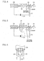
- the liquid droplets (22) adhering to the discharge electrode (21) are pulled towards the tip of the discharge electrode (21) by ionic wind generated with the generation of electric discharge and, as a result, a film of water is formed on the tip of the discharge electrode (21) (see Figure 3(A) ). Consequently, electric discharge is generated to the liquid droplets (22) from the water film.
- the tip of the discharge electrode (21) is covered with a film of water and electric discharge is initiated over the water film, as a result of which the discharge electrode (21) is cooled and no degradation due to oxidation occurs.
- the tip of the discharge electrode (21) is free also from the adhesion of contaminants. Consequently, electric discharge is stably generated and the service life of the discharge electrode (21) extends.
- materials having good staying power such as tungsten are generally used to form the discharge electrode (21) for streamer discharge.
- the liquid droplets (22) are used as the counter electrode (22) , which makes it possible to stably use materials, inferior in durability to stainless or the like but superior in resistance to corrosion, over a long period of time.
- electric discharge can be generated in stable manner in the electric discharge device (20) which is configured such that the granular particulate ejector (24) and the discharge electrode (21) are situated face to face with each other.
- the granular particulates (22) are ejected towards a hollow circular conical region around the discharge electrode (21) from the granular particulate ejector (24) . Accordingly, streamer discharge is formed stably with a flared spread.
- this setting is optimum to render the shape of spray pattern hollow.
- This spray pattern shape is determined by the balance of the inertia force of the granular particulate and the ionic wind ( Figure 3(B) ) and the shape of spray pattern is made hollow by the generation of ionic wind towards the granular particulate from the discharge electrode. If the granular particulate is smaller than the aforesaid range and light, it will be blown away by ionic wind.
- the granular particulates (22) are ejected towards a solid circular conical region including the discharge electrode (21) from the granular particulate ejector (24) . Accordingly, streamer discharge is formed into a column shape with almost no flared spread.
- the granular particulates (22) are ejected substantially linearly from the granular particulate ejector (24) and streamer discharge is generated to the flow of the granular particulates (22) from the discharge electrode (21) situated lateral to the granular particulate flow.
- the granular particulates (22) ejected from the granular particulate ejector (24) can be recovered in the granular particulate recovery container (45) .
- the granular particulates (22) recovered by the granular particulate recovery container (45) can be ejected again from the granular particulate ejector (24) for reuse thereof.
- the electric discharge device (20) in which electric discharge is generated between the granular particulate (22) ejected from the granular particulate ejector (24) and the discharge electrode (21) , is employed in an air purification device.
- This makes it possible to stabilize the state of electric discharge (especially, streamer discharge) and to stably carry out, with the aid of various active species contained in low temperature plasma gas in the electric discharge field, treatment of air to be treated.
- the level of performance of the air purification device (10) can highly be stabilized.
- the granular particulate recovery unit (40) is disposed downstream, relative to the direction of flow of the air to be treated, of the electric discharge device (20) .
- This arrangement makes it possible for the granular particulate recovery unit (40) to recover the granular particulates (22) that have flowed further ahead of the discharge electrode (21) , whereby the granular particulates (22) recovered can be reused.
- the direction of flow of the air to be treated and the direction of ejection of the granular particulates (22) are made opposite to each other.
- This arrangement makes it possible to enhance the efficiency of contact between the air to be treated and the granular particulates (22) . Accordingly, especially in the case where the granular particulate is in the form of a liquid droplet, it is possible for the liquid droplet (22) to absorb therein the odorous component present in the air to be treated, thereby achieving improvement in the performance of removal of the odorous component.
- the dust collecting means (54) is disposed upstream of the electric discharge device (20) .
- This arrangement makes it possible to prevent dust particles and other substances present in the air to be treated from adhering to the discharge electrode (21) and the granular particulate ejector (24) in the electric discharge device (20) . Accordingly, it is further ensured that the discharge electrode (21) and the granular particulate ejector (24) are protected from contamination, thereby making it possible to further stabilize the state of electric discharge by the electric discharge device (20) .
- the catalytic treatment part (55) is disposed downstream of the electric discharge device (20) .
- This arrangement enhances the activation of the catalytic treatment part (55) , thereby ensuring the further removal of the odorous component or the like present in the air to be treated. Accordingly, the performance of the air purification device can be enhanced effectively.
- the adsorptive treatment part (57) is disposed downstream of the electric discharge device (20) .
- This arrangement ensures that the odorous component of low-concentration or the like still remaining in the air to be treated can be removed without fail. Accordingly, the performance of the air purification device can be effectively made stable.
- the provision of the temperature controlling means for controlling the temperature of the air to be treated makes it possible to not only remove the odorous and noxious components from the air to be treated but also provide, for example, room air conditioning with temperature-controlled air.
- an air cleaner air conditioning system
- a first embodiment of the present invention is an example of the application of an air purification device (10) including an electric discharge device (20) of the present invention to an exhaust duct by which exhaust air in a restaurant kitchen is expelled outdoors.
- Figure 1 is a schematic of a kitchen exhaust system (1) including the air purification device (10) .
- FIG. 1 there is shown an exhaust hood (3) mounted above a cooking appliance (2) arranged in the kitchen.
- One end (indoor side end) of an exhaust duct (4) extending to outside the building is connected to the exhaust hood (3) .
- the other end (outdoor side end) of the exhaust duct (4) is connected to an exhaust fan (5) .
- kitchen exhaust air i.e., air to be treated, is released outdoors after being passed sequentially through the exhaust hood (3), then through the exhaust duct (4) , and then through the exhaust fan (5).
- a grease filter (6) for collecting an oil mist (M1) and dust (not shown) contained in the kitchen exhaust air is disposed in the exhaust hood (3) .
- an oil pan (7) for receiving waste oil is placed below the grease filter (6) .
- the kitchen exhaust air contains, in addition to the oil mist (M1) and dust, an odorous component (S1). And, the air purification device (10) of the present invention is mounted in the middle of the exhaust duct (4) so that the oil mist (M1) and the odorous component (S1) past the grease filter (6) are removed.
- the air purification device (10) has, as a main constituent element thereof, a streamer discharge part (electric discharge device) (20) for decomposing the odorous component (S1).
- the streamer discharge part (20) decomposes the odorous component or the like with the aid of active species produced by streamer discharge.
- the streamer discharge part (20) serves also as a scrubber for dispersing a cleaning liquid (water) to the kitchen exhaust air so that oil mist and dust particles are collected by droplets of the liquid.
- An ionization part (30) for electrically charging the dust (dust particles) and the oil mist (M1) present in the kitchen exhaust air is disposed upstream of the streamer discharge part (20) .
- a demister (41) for collecting the electrically-charged dust particles is disposed downstream, relative to the direction of flow of the kitchen exhaust air, of the streamer discharge part (20) .
- a recovery tank (42) is disposed so as to collect liquid droplets adhering to the demister (41) after ejection from the streamer discharge part (20) when they fall from the demister (41).
- the demister (41) and the recover tank (42) together constitute a liquid droplet collecting device (granular particulate recovery device) (40) .
- the ionization part (30) causes the oil mist (M1) and dust of relatively small size past the grease filter (6) to be electrically charged, whereby the collecting of these oil mist/dust particles by the demister (41) is facilitated.
- the demister (41) is connected to an earth electrode so that the oil mist/dust particles electrically charged are collected because of the difference between their electric potential and the electric potential of the demister (41) .
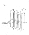
- the ionization part (30) is composed of a plurality of ionization lines (31) and a plurality of counter electrodes (32). Being equally spaced, the plurality of ionization lines (31) extend from top to bottom of the ionization part (30) . Each ionization line (31) lies on a single virtual surface in parallel with the other. Each counter electrode (32) has, in a front plate-like portion thereof, an opening (32a) for ventilation, and is provided, between each ionization line (31) , with a partition plate (electrode plate).
- Each ionization line (31) of the ionization part (30) is connected to the positive pole of an electric power supply (34) for the ionization part and each counter electrode (32) is connected to the negative pole of the electric power supply (34) .
- the ionization line (31) and the counter electrode (32) are electrically insulated from each other by an insulator (not shown).
- the streamer discharge part (20) includes a discharge electrode (21) , a counter electrode (22) , and an electric power supply (23) for the electric discharge device for providing a difference in electric potential between both the electrodes (21, 22) .
- the streamer discharge part (20) generates streamer discharges from the discharge electrode (21) towards the counter electrode (22) .
- the streamer discharge part (20) is provided, in addition to the discharge electrode (21) formed by a needle-shaped electrode, with a liquid droplet ejector (granular particulate ejector) (24) for spraying droplets of liquid.
- the liquid droplets ejected from the liquid droplet ejector (24) towards the discharge electrode (21) are used as the counter electrode ( 22) .
- the liquid droplet ejector (24) is configured such that the liquid droplets (22) are ejected towards a circular conical region around the discharge electrode (21).
- the mutual relationship in position between the discharge electrode (21) and the liquid droplet ejector (24) is determined so that, according to the difference in electric potential between the discharge electrode (21) and the counter electrode (22) (composed of liquid droplets), there is generated a streamer discharge between the discharge electrode (21) and the liquid droplets (22) .
- the direction of ejection of the liquid droplets (22) from the liquid droplet ejector (24) is substantially oriented to the discharge electrode (21) and the tip of the discharge electrode (21) is substantially oriented to the liquid droplet ejector (24).
- the discharge electrode (21) and the liquid droplet ejector (24) are arranged face to face with each other.
- the shape of ejection pattern of the liquid droplets (22) from the liquid droplet ejector (24) is determined to have a hollow circular conical shape centered on the discharge electrode (21).
- this setting is suitable for providing a shape of spray pattern which is a hollow circular cone.
- the spray pattern shape is determined by the balance between the liquid droplet's inertial force and the ionic wind, and the generation of a flow of ionic wind from the discharge electrode towards the liquid droplets provides a hollow spray pattern shape ( Figure 3(B) ).
- the liquid droplets if their grain diameter falls below the aforesaid range and they are light, will be blown off by ionic wind.
- liquid droplets have a grain diameter exceeding the aforesaid range and are heavy, this impedes the formation of a hollow spray pattern shape because the inertial force is great.
- spray pattern shape becomes hollow, this provides an electric discharge with a flared spread.
- the streamer discharge part (20) is provided with a water tank (25) for holding cleaning liquid (water) and a water supply pipe (26) for the supply of liquid (water) from the water tank (25) to the liquid droplet ejector (24) .
- the positive pole of the electric power supply (23) for the electric discharge device is connected to the discharge electrode (21) and the negative pole thereof is connected to the liquid droplet ejector's (24) side.
- the kitchen exhaust air is subjected to treatment such as the removal of the oil mist (M1) and dust particles and the decomposition of the odorous component (S1).
- the oil mist (M1) and the dust are electrically charged in the ionization part (30) .
- the manner of this change is represented, in the figure, by the change in shape of the oil mist, that is, from the pentagonal oil mist (M1) to a circular oil mist (M2).
- cleaning liquid water
- the liquid droplet ejector (24) Since the oil mist (M2) and the dust change from hydrophobic to hydrophilic form by the action of streamer discharge, they are absorbed in droplets (D) of the cleaning liquid, adhere to the demister (41) together with the cleaning liquid, and fall downwards therefrom, and are recovered in the recovery tank (42) .
- the recovery tank (42) In addition, although not shown in the figure, there occurs a separation of the cleaning liquid and the oil in the recovery tank (42) , and the oil floats on the surface of the cleaning liquid.
- streamer discharge is generated from the tip of each discharge electrode (21) towards the liquid droplets (22) serving as the counter electrode (22).
- the streamer discharge is formed, by a continuous series of minute electric arcs from the tip of the discharge electrode (21) to the liquid droplets (22) , as a plasma column with luminescence.
- minute electric arc spreads in the form of a flare and advances between the tip of the discharge electrode (21) and the liquid droplets (22) .
- the liquid droplets (22) are induced by an electric field between the discharge electrode (21) and the liquid droplet ejector (24) and jump out from the liquid droplet ejector (24) with negative electric charges. Then, there is produced an electron avalanche from the liquid droplets (22) of negative electric charge towards the discharge electrode (21) of positive electric charge, as a result of which the liquid droplets (22) lose the negative electric charges, thereby entering the electrically neutral state.
- a minute electric arc (column), which is called a "leader" of positive electric charge, advances towards the liquid droplets (22) from the discharge electrode (21) .
- the positively-charged liquid droplets (22) stand still or are travelling towards the liquid droplet ejector (24) , this causes the possibility that the leader may further advance with the movement of the liquid droplets (22) to become an electric spark.
- the liquid droplets (22) travel in a direction moving away from the liquid droplet ejector (24) and, besides, there exists a space between the liquid droplets (22) which space functions as an insulator. As a result, the leader will not advance further. That is, the leader is unable to change to an electric spark.
- the streamer discharge is an electric discharge that repeats a series of cycles (i.e., "electron avalanche" ⁇ "leader formation” ⁇ “leader extinction” ⁇ ”electron avalanche and so on).
- a series of cycles is repeated in ideal form, whereby streamer discharge is stably formed as a flared plasma column with luminescence
- low temperature plasma gas is generated in the electric discharge filed.
- the gas thus generated contains, as active species, fast electrons, ions, ozone, radicals such as hydroxyl radicals, and other excited molecules (e.g., excited oxygen molecules, excited nitrogen molecules, excited water molecules et cetera). And, these active species starts to flow in a direction downstream of the flow of kitchen exhaust air.
- the rest of the odorous component (S1) bonds to active species such as electrons and various excited molecules and changes from hydrophobic (lipophilic) to hydrophilic form.
- the manner of this change is represented, in the figure, by the change in shape of the odorous component, that is, from the odorous component (S1) in the shape of a cross to an odorous component (S2) in the shape of a circle.
- the odorous component (S2) which has changed to hydrophilic form, dissolves in the liquid droplets (22) of the cleaning liquid (water) in the streamer discharge part (20) serving also as a scrubber.
- the remaining active species are also collected in the liquid droplets (22) of the cleaning liquid. Accordingly, the hydrophilic odorous component (S2) remaining undecomposed and the active species which have not used for the decomposition of the odorous component are also collected in the recovery tank (42) .
- the odorous component (S1) is decomposed by the action of the active species during the time from when the liquid droplets (22) of the cleaning liquid are in the middle of dropping from the demister (41) until when the liquid droplets (22) are recovered in the recovery tank (42) .
- the counter electrode (22) is in the form of liquid droplets.
- the generation of electric sparking can be prevented by a space created between the liquid droplets (22) .
- the advance of a leader from the discharge electrode (21), the extinction of the leader, the occurrence of an electron avalanche from the liquid droplet (22) and so on) owing to the arrangement that the discharge electrode (21) serves as a positive pole and the liquid droplet ejector (24) serves as a negative pole, and also thanks especially to the arrangement that the liquid droplet ejector (24) and the discharge electrode (21) are oriented face to face with each other, the occurrence of electric sparking is prevented whereby the state of streamer discharge is stabilized. Accordingly, the applying of the electric discharge device (20) to the air purification system (
- liquid droplets (22) are ejected from the liquid droplet ejector (24) towards a hollow circular conical region around the discharge electrode (21) .
- streamer discharge is stably formed having a flared spread.
- pollutants are decomposed by active species, such as fast electrons et cetera, in a discharge space plasmized by streamer discharge.
- streamer discharge activates O 2 and N 2 constituting air to produce radicals such as OH.
- radicals also decompose pollutants.
- OH radicals having strong oxidative power are produced with the aid of the presence of H 2 O. Accordingly, if streamer discharge is generated while spraying the liquid (water) droplets (22) , this leads to an increase in the amount of generation of OH radicals. This is extremely effective for the decomposition of pollutants.
- the electric discharge device (20) initiates streamer discharge, whereby a part of the odorous component (S1) is decomposed by the streamer discharge and, in addition, the rest of the odorous component (S1) changes from hydrophobic to hydrophilic form, thereby making it possible for the electric discharge device (20) to capture the odorous component (S2) together with the remaining active species by using a function as a scrubber. Accordingly, since the action of decomposition of the odorous component (S2) can be obtained also by the scrubber, this makes it possible to satisfactorily treat the odorous component (S1) contained in the kitchen exhaust air.
- the tip of the discharge electrode (21) is free also from the adhesion of contaminants. This provides stable electric discharge and therefore increases the service life of the discharge electrode (21) .
- materials having good staying power such as tungsten are generally used to form the discharge electrode (21) for streamer discharge.
- water is used in the first embodiment, which makes it possible to stably use materials, inferior in durability to stainless or the like but superior in resistance to corrosion, over a long period of time.
- the shape of spray pattern of the liquid droplets (22) from the liquid droplet ejector (24) has a hollow circular conical shape.
- the shape of spray pattern may have a solid circular conical shape.
- the shape of spray pattern is limited to neither a hollow circular conical shape nor a solid circular conical shape.
- the shape of spray pattern may have different shapes other than those described above.
- the granular particulate ejector (24) may be implemented by either a gas-liquid two-fluid nozzle, a ultrasonic atomizer, or an electrostatic atomizer.
- the present invention provides a second embodiment as an example that differs, in the relationship in position between the liquid droplet ejector (24) and the discharge electrode (21) , from the first embodiment, as shown in Figure 4 . More specifically, it is configured such that the liquid droplet ejector (24) linearly sprays the liquid droplets (22) and, in addition, the tip of the discharge electrode (21) is oriented from sideways to the direction of flow of the liquid droplets (22) sprayed from the liquid droplet ejector (24) (approximately at right angles to the direction of flow of the liquid droplets (22) ).
- the electric discharge device (20) of the second embodiment is provided with a ring-shaped guide member (27) through which hollow space the liquid droplets (22) sprayed from the liquid droplet ejector (24) are passed, as shown in Figure 5 .
- a ring-shaped guide member (27) through which hollow space the liquid droplets (22) sprayed from the liquid droplet ejector (24) are passed, as shown in Figure 5 .
- the present invention provides a third embodiment as an example of the application of an air purification device, which is provided with the electric discharge device (20) of the present invention, to an air cleaner (10) for general household use.
- the air cleaner (10) is for cleansing an indoor space by removing substances present in the room air such as odorous and noxious components, dust particles and so on.
- the air cleaner (10) has a rectangular casing (50).
- the casing (50) is provided, in its front surface, with an air intake opening (51) , and an air delivery opening (52) is formed in the upper surface. And, there is provided in the casing (50) an air passageway (53) extending from the air intake opening (51) to the air delivery opening (52) . Room air, i.e., air to be treated, is passed through the air passageway (53).
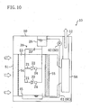
- a dust collecting filter (54) , a streamer discharge part (20) , a catalytic treatment part (55) , and an air supply fan (56) are disposed, sequentially in the order from upstream to downstream side, in the air passageway (53) .
- the dust collecting filter (54) constitutes a dust collecting means for physically collecting dust particles of relatively large size present in the room air.
- the streamer discharge part (20) generates a streamer discharge, whereby odorous and noxious components and the like are oxidatively decomposed by active species generated by the streamer discharge, as in the case of each of the aforesaid embodiments.
- the catalytic treatment part (55) is constructed such that it supports, on its substrate surface, a catalyst.
- catalysts of the manganese family and catalysts of the noble metal family may be used as the catalyst that the catalytic treatment part (55) can support thereon.
- the streamer discharge part (20) is provided with a plurality of discharge electrodes (21) and a plurality of liquid droplet ejectors (24) .
- Each discharge electrode (21) is formed by a needle-shaped electrode and is arranged in the air passageway (53) in such an orientation that it extends vertically.
- Each liquid droplet ejector (24) is so arranged above its associate discharge electrode (21) as to face the tip thereof.
- Each liquid droplet ejector (24) is connected through the water supply pipe (26) to the water tank (25) , as in the aforesaid embodiments. That is, it is configured such that the supply of water held in the water tank (25) is provided to each liquid droplet ejector (24) .
- Each liquid droplet ejector (24) is configured such that the liquid droplets (22) which become granular particulates are ejected downwardly.
- the shape of spray pattern of the liquid droplets (22) from the liquid droplet ejector (24) is determined to have a hollow circular conical shape centered on the discharge electrode (21) , as in the first embodiment.
- the streamer discharge part (20) is provided with an electric power supply (23) for the electric discharge device.
- the positive side of the electric power supply (23) for the electric discharge device is connected to the discharge electrode (21).
- the negative side of the electric power supply (23) for the electric discharge device is connected through the water supply pipe (26) to the liquid droplet ejector (24) . That is, like the aforesaid first embodiment, the liquid droplets (22) sprayed from the liquid droplet ejector (24) are electrically negatively charged, and constitute a counter electrode for the discharge electrode (21) .
- the streamer discharge part (20) there is provided between the discharge electrode (21) and the liquid droplet ejector (24) an electric potential difference, as in the aforesaid first embodiment.
- a streamer discharge in the form of a flare advances towards the liquid droplets (22) from the tip of the discharge electrode (21) .
- the streamer discharge part (20) of the third embodiment is provided with a water recovery container (45) and a water circulating mechanism (60) .
- the water recovery container (granular particulate recovery container) (45) is situated underneath the liquid droplet ejector (24) and is mounted on the bottom of the casing (50) .
- the water recovery container (45) is so configured as to be capable of recovery of the liquid droplets (22) ejected from the liquid droplet ejector (24).
- the water recovery container (45) is so configured as to be capable of attachment to and detachment from the casing (50).
- the casing (50) has an access opening through which to pull out the water recovery container (45) to outside the casing (50) , and an openable and closable cover for the access opening (diagrammatical representation is omitted). That is, the water recovery container (45) is so configured as to be capable of freely being taken out from and inserted into the casing (50) .
- the water circulating mechanism (granular particulate circulating mechanism) (60) is configured such that it returns the liquid (water) droplets (22) , recovered in the water recovery container (45) , to the liquid droplet ejector's (24) side.
- the water circulating mechanism (60) is provided with circulation piping (61) and a circulation pump (62) .
- One end of the circulation piping (61) is connected to the water recovery container (45) and the other end thereof is connected to the water tank (25) .
- the circulation pump (62) is disposed in the circulation piping (61).
- the circulation pump (62) is configured such that it delivers, by pressure, water accumulated in the water recovery container (45) to the water tank (25) .
- the air supply fan (56) is placed in operation, and room air is introduced through the air intake-opening (51) into the air passageway (53) .
- the dust collecting filter (54) captures dust particles contained in the room air. Thereafter, the room air passes through the vicinity of the discharge electrode (21) and the liquid droplet ejector (24) in the streamer discharge part (20) .
- the liquid droplets (22) are ejected downwardly from each of the liquid droplet ejectors (24) .
- the electric power supply (23) for the electric discharge device provides an electric potential difference between the liquid droplet ejector (24) and the discharge electrode (21) .
- a minute electric arc advances between the discharge electrode (21) and the liquid droplets (22) such that it spreads upwardly.
- the streamer discharge part (20) of the third embodiment too, generates an electric discharge that repeats a series of cycles (i.e., "electron avalanche" ⁇ "leader formation “leader extinction” ⁇ ”electron avalanche” and so on), whereby streamer discharge is stably formed as a flared plasma column with luminescence (see Figure 3(A) ), as in the case of the first embodiment.
- streamer discharge part (20) fast electrons, ions, ozone, radicals (such as hydroxyl radicals), and other excited molecules (excited oxygen molecules, excited nitrogen molecules, excited water molecules et cetera) are generated in the air passageway (53) .
- the odorous and noxious components contained in the air to be treated are oxidatively decomposed by the aforesaid active species.
- the hydrophilic odorous component or the like contained in the air to be treated is absorbed in the liquid droplets (22) ejected from the liquid droplet ejector (24) .
- minute particulates (such as dust particles) contained in the air to be treated are physically absorbed in the liquid droplets (22).
- the air to be treated passes, together with active species, through the catalytic treatment part (55) .
- the odorous component or the like lingering in the air to be treated is oxidatively decomposed by catalyst.
- the passage of the active species through the catalytic treatment part (55) enhances the catalytic action of the catalytic treatment part (55) , whereby the odorous component or the like is oxidatively decomposed to a further extent.
- the air to be treated which has been purified in the way as described above, is supplied indoors through the air delivery opening (52) .
- the dust collecting filter (54) is disposed upstream of the streamer discharge part (20) .
- This arrangement prevents the adhesion of dust particles of relatively large size contained in the air to be treated to the discharge electrode (21) and to the liquid droplet ejector (24).
- the air cleaner (10) is operated over a long period of time, neither the shape of spray pattern of the liquid droplets (22) ejected from the liquid droplet ejector (24) nor the properties of electric discharge advancing from the discharge electrode (21) will not be damaged. Therefore, the state of streamer discharge from the streamer discharge part (40) becomes further stabilized.
- the catalytic treatment part (55) is disposed downstream of the streamer discharge part (20) .
- the power of decomposition of the odorous component in the catalytic treatment part (55) is enhanced by active species generated in the streamer discharge part (20). This further ensures the removal of the odorous component remaining in the air to be treated.
- the water recovery container (45) underlies the liquid droplet ejector (24) , thereby ensuring the recovery of water sprayed from the liquid droplet ejector (24) .
- the water recovery container (45) can be put in and taken out from the casing (50) , thereby facilitating the maintenance of the water recovery container (45) .
- water recovered in the water recovery container (45) is returned to the water tank (25) by the water circulating mechanism (60) and the water thus recovered is ejected again from the liquid droplet ejector (24) .
- the water circulating mechanism (60) As a result of such arrangement, it is possible to cut down the amount of consumption of the water required for the generation of streamer discharge, thereby reducing the running cost of the air cleaner (10).
- dust collecting means for example, electric dust collectors, cyclone dust collectors, scrubber dust collectors et cetera
- these dust collecting means may capture, on the side upstream of the streamer discharge part (20) , dust particles present in the air to be treated, thereby positively ensuring prevention of the adhesion of dust particles or the like to the liquid droplet ejector (24) and the discharge electrode (21) in the streamer discharge part (20) .
- an adsorptive treatment part (57) may be disposed downstream of the streamer discharge part (20).
- the adsorptive treatment part (57) is configured such that it supports, on the surface of an air distributable substrate thereof, an adsorbent such as active carbon or the like. This configuration makes it possible that the component to be treated, which is still remaining in the air to be treated, is absorption removed by the adsorptive treatment part (57) after the passage through the streamer discharge part (20).
- the spray operation of the liquid droplet ejector (24) is forced to a stop upon the detection that the water recovery container (45) of the third embodiment is extracted out from within the casing (50).
- This configuration prevents the occurrence of a situation where the liquid droplets (22) are accidentally ejected from the liquid droplet ejector (24) even after the detachment of the water recovery container (45) from the casing (50).
- a water treatment device for the treatment of a noxious component or the like present in the water recovered in the water recovery container (45) .
- the liquid droplet ejector (24) may be configured such that the liquid droplets (granular particulates) (22) are ejected in a direction opposite to the direction of flow of the air to be treated.
- the efficiency of contact between the liquid droplets (22) ejected from the liquid droplet ejector (24) and the air to be treated is improved, thereby making it possible to achieve effective absorption of the air to be treated into the liquid droplets (22). Accordingly, it is possible to improve the performance of the air cleaner (10) .
- a temperature controlling means such as a heat exchanger, a heater, a cooler et cetera for controlling the temperature of the air to be treated.
- a temperature controlling means such as a heat exchanger, a heater, a cooler et cetera
- each of the electric discharge devices (streamer discharge parts) of the first and second embodiments and their modifications may be employed in the air cleaner (10) of the third embodiment.
- the air purification device (10) of the present invention may be applied to other than the kitchen exhaust system (1) .
- the electric discharge device (20) of the present invention uses granular particulates such as liquid (water) droplets as the counter electrode (22) for the stabilization of electric discharge (streamer discharge), and may be applied to any device other than the air purification device (10) as long as it utilizes electric discharge (streamer discharge).
- the liquid droplet ejector (24) is of the funnel type which is oriented facedown so that the liquid droplets (22) drop (as shown in Figure 6 ) while the discharge electrode (21) is oriented faceup so as to face the funnel type liquid droplet ejector (24) .
- This configuration also provides the same effects that each of the foregoing embodiments does.
- the discharge electrode (21) may be composed of a plurality of needle-shaped electrodes (21a). If, as described above, the discharge electrode (21) is composed of a plurality of needle-shaped electrodes (21a) , this makes it possible, even when there is a needle-shaped electrode (21a) whose state of electric discharge is unstable, to further stabilize the state of electric discharge because of the existence of the other needle-shaped electrodes (21a) .
- the applying of the electric discharge device (20) to the air purification device (10) makes it possible to stabilize also the performance of the air purification device (10) .
- the using of a plurality of needle-shaped electrodes (21a) as the discharge electrode (21) provides an expanded discharge area, and it becomes possible to provide improvement in treatment performance by increasing the generation amount of active species.
- the discharge electrode (21) may be formed as follows. For example, a thin plate of stainless steel is formed into a shape having a plurality of needle parts (21a) each extending radially from a center part (21b) (see Figure 8(A) ). The stainless steel thin plate thus formed is bent to obtain a member as shown in Figure 8(B) and this member serves as the discharge electrode (21) .
- the electric power supply (23) used for the streamer discharge part (20) a dc high voltage electric power supply or a pulse high voltage electric power supply may be used.
- the discharge electrode (21) is a positive pole.
- the discharge electrode (21) may be a negative pole.
- the ionization part (30) is provided in the air purification device (10) with a view to enhancing the effect of dust collection.
- the liquid droplet ejector (24) is used and the counter electrode (22) is composed of liquid droplets.
- the counter electrode (22) does not always have to be in the form of liquid droplets.
- a granular particulate ejector capable of ejecting minute granular particulates wherein such granular particulates ejected to the discharge electrode (21) from the granular particulate ejector serve as the counter electrode (22) .
- the "granular particulate" may be in the form a "powder particulate”.
- the granular particulate ejector may employ a configuration capable of ejecting granular particulates or powder substances by means of pressure or wind power.
- the present description finds industrial utility in the field of electric discharge devices (such as the electric discharge device (20) ) for the generation of a low temperature plasma by means of electric discharge, and air purification devices (such as the air purification device (10) ) for the purification of air by making utilization of a low temperature plasma generated by such an electric discharge device.
- electric discharge devices such as the electric discharge device (20)
- air purification devices such as the air purification device (10)
Applications Claiming Priority (3)
| Application Number | Priority Date | Filing Date | Title |
|---|---|---|---|
| JP2006140104 | 2006-05-19 | ||
| JP2006166237A JP4111229B2 (ja) | 2006-05-19 | 2006-06-15 | 放電装置及び空気浄化装置 |
| PCT/JP2007/059577 WO2007135860A1 (ja) | 2006-05-19 | 2007-05-09 | 放電装置及び空気浄化装置 |
Publications (3)
| Publication Number | Publication Date |
|---|---|
| EP2019464A1 EP2019464A1 (en) | 2009-01-28 |
| EP2019464A4 EP2019464A4 (en) | 2012-11-14 |
| EP2019464B1 true EP2019464B1 (en) | 2015-04-08 |
Family
ID=38723173
Family Applications (1)
| Application Number | Title | Priority Date | Filing Date |
|---|---|---|---|
| EP07743012.2A Not-in-force EP2019464B1 (en) | 2006-05-19 | 2007-05-09 | Discharge device and air purifying device |
Country Status (7)
| Country | Link |
|---|---|
| US (1) | US20090263293A1 (zh) |
| EP (1) | EP2019464B1 (zh) |
| JP (1) | JP4111229B2 (zh) |
| KR (1) | KR100983403B1 (zh) |
| CN (1) | CN101443970B (zh) |
| AU (1) | AU2007252721B2 (zh) |
| WO (1) | WO2007135860A1 (zh) |
Families Citing this family (30)
| Publication number | Priority date | Publication date | Assignee | Title |
|---|---|---|---|---|
| JP4023512B1 (ja) * | 2006-06-15 | 2007-12-19 | ダイキン工業株式会社 | 液処理装置、空気調和装置、及び加湿器 |
| JP5040612B2 (ja) * | 2007-11-22 | 2012-10-03 | ダイキン工業株式会社 | 空気浄化装置 |
| FR2927550B1 (fr) | 2008-02-19 | 2011-04-22 | Commissariat Energie Atomique | Dispositif de filtration electrostatique au moyen de sites emissifs optimises. |
| JP2010017698A (ja) * | 2008-07-10 | 2010-01-28 | Tds:Kk | 直流ストリーマ放電の放電素子および有害物質除去装置 |
| KR100932102B1 (ko) * | 2009-03-05 | 2009-12-16 | 운해이엔씨(주) | 영상정보를 제공하는 주방용 살균 및 탈취시스템 |
| GB2468865B (en) | 2009-03-24 | 2014-04-16 | Tri Air Developments Ltd | Improved air decontamination device |
| FI123025B (fi) * | 2011-01-12 | 2012-10-15 | Aavi Technologies Oy | Laite ja menetelmä ilman puhdistamiseksi ei-toivotuista ainesosista ja niiden eliminoimiseksi |
| CN103586131A (zh) * | 2012-10-17 | 2014-02-19 | 江苏大学 | 一种静电雾化室内空气的净化装置与方法 |
| CN103900155B (zh) * | 2012-12-26 | 2017-06-16 | 广州市拓丰电器有限公司 | 水离子空气净化器 |
| JP6090637B2 (ja) * | 2013-03-11 | 2017-03-08 | パナソニックIpマネジメント株式会社 | 有効成分発生装置 |
| US20160151530A1 (en) * | 2013-07-31 | 2016-06-02 | Hitachi, Ltd. | Sanitization Device Using Electrical Discharge |
| CN104324805A (zh) * | 2013-08-20 | 2015-02-04 | 石家庄虎林环保设备有限公司 | 一种电除尘水雾荷电凝并捕集pm2.5微细粒子的方法 |
| WO2015085864A1 (zh) * | 2013-12-09 | 2015-06-18 | 罗瑞真 | 空气净化装置及方法 |
| JP5761424B2 (ja) * | 2013-12-27 | 2015-08-12 | ダイキン工業株式会社 | 放電装置及び空気処理装置 |
| CN104764102B (zh) * | 2014-01-02 | 2018-04-03 | 苏州艾润环境科技有限公司 | 一种室内空气净化装置 |
| EP3107639A1 (en) * | 2014-02-18 | 2016-12-28 | Ugra Alternative Energy S.R.L. | Method and apparatus for purifying a gas containing pollutants |
| CN104138699B (zh) * | 2014-07-29 | 2015-10-14 | 张利峰 | 一种静电水雾空气净化装置 |
| JP2016079412A (ja) * | 2014-10-09 | 2016-05-16 | 東レKpフィルム株式会社 | 真空蒸着システム |
| SG11201805241SA (en) * | 2015-12-24 | 2018-07-30 | Mitsubishi Electric Corp | Water treatment device and water treatment method |
| TWI634951B (zh) * | 2016-07-21 | 2018-09-11 | 報知機股份有限公司 | Electrostatic spray generating device and charged water particle dispersing device |
| KR102540335B1 (ko) * | 2016-12-09 | 2023-06-05 | 삼성전자주식회사 | 전기집진장치 및 이를 포함하는 가습공기청정기 |
| CN108273662B (zh) * | 2018-01-05 | 2023-07-18 | 老肯医疗科技股份有限公司 | 一种用于城市除雾霾的空气净化器 |
| JP2019118897A (ja) * | 2018-01-10 | 2019-07-22 | エイチピー プリンティング コリア カンパニー リミテッド | 電気集塵装置 |
| KR102123123B1 (ko) * | 2018-02-09 | 2020-06-15 | 주식회사 포워드메디 | 라디칼을 이용한 저온창고의 탈취 및 살균 제어장치 |
| CN109759233B (zh) * | 2019-01-25 | 2021-05-18 | 东南大学 | 一种协同处理脱硫废水和强化细颗粒物团聚与脱除的系统及方法 |
| JP2021133261A (ja) * | 2020-02-21 | 2021-09-13 | パナソニックIpマネジメント株式会社 | 静電噴霧用組成物および静電噴霧装置 |
| US11187422B1 (en) * | 2020-10-01 | 2021-11-30 | Clyde Richards | Air purifier/conditioner (APC) |
| WO2022217237A1 (en) * | 2021-04-07 | 2022-10-13 | Evo America, Llc | Cleaning a cooking system |
| KR102390224B1 (ko) * | 2021-08-02 | 2022-04-25 | 안종한 | Cnt 전극을 이용한 공기 살균 정화장치 |
| WO2023244730A1 (en) * | 2022-06-15 | 2023-12-21 | Ying Zhong | Robotic and ai-augmented in situ detection and disinfection platform |
Family Cites Families (17)
| Publication number | Priority date | Publication date | Assignee | Title |
|---|---|---|---|---|
| US3744216A (en) * | 1970-08-07 | 1973-07-10 | Environmental Technology | Air purifier |
| JPS6019022A (ja) * | 1983-07-12 | 1985-01-31 | Tamao Nakao | 脱臭処理法 |
| US4780277A (en) * | 1985-05-10 | 1988-10-25 | Shinryo Corporation | Method and apparatus for subjecting gases to discharge treatment |
| US5232676A (en) * | 1990-08-10 | 1993-08-03 | Bayer Aktiengesellschaft | Process for the biological purification of waste air streams |
| FR2680474B1 (fr) * | 1991-08-21 | 1995-09-08 | Ecoprocess Sarl | Reacteur electrostatique a contacts gaz liquide solide a contre courant gaz liquide et a etages multiples pour l'epuration d'un gaz et des liquides de transfert. |
| WO1996006706A1 (en) * | 1994-09-01 | 1996-03-07 | Refranco Corp. | Treatment of particulate matter by electrical discharge |
| US6174500B1 (en) * | 1998-06-02 | 2001-01-16 | Mitsubishi Denki Kabushiki Kaisha | Negative ion generating apparatus |
| JP3496588B2 (ja) * | 1999-09-14 | 2004-02-16 | ダイキン工業株式会社 | 空気清浄機およびそのイオン化ユニット |
| US6656253B2 (en) * | 2000-05-18 | 2003-12-02 | The Procter & Gamble Company | Dynamic electrostatic filter apparatus for purifying air using electrically charged liquid droplets |
| JP4300737B2 (ja) | 2001-05-21 | 2009-07-22 | ダイキン工業株式会社 | プラズマ反応器及び空気浄化装置 |
| JP4543603B2 (ja) * | 2001-05-28 | 2010-09-15 | ダイキン工業株式会社 | プラズマ式ガス浄化装置及びストリーマ放電回路 |
| GB0115355D0 (en) * | 2001-06-22 | 2001-08-15 | Pirrie Alastair | Vaporization system |
| DE10132582C1 (de) * | 2001-07-10 | 2002-08-08 | Karlsruhe Forschzent | Anlage zum elektrostatischen Reinigen von Gas und Verfahren zum Betreiben derselben |
| US20040005252A1 (en) * | 2001-07-20 | 2004-01-08 | Siess Harold Edward | Preventing the transmission of disease |
| JP3984059B2 (ja) | 2002-01-21 | 2007-09-26 | 川崎重工業株式会社 | 排ガス浄化装置 |
| AU2003256189A1 (en) * | 2002-03-25 | 2003-10-08 | The Board Of Trustees Of The University Of Illinois | Method for abatement of voc in exhaust gases by wet pulse corona discharge |
| JP3966418B2 (ja) * | 2004-10-01 | 2007-08-29 | 大同メタル工業株式会社 | オイルミスト生成装置 |
-
2006
- 2006-06-15 JP JP2006166237A patent/JP4111229B2/ja not_active Expired - Fee Related
-
2007
- 2007-05-09 US US12/301,385 patent/US20090263293A1/en not_active Abandoned
- 2007-05-09 AU AU2007252721A patent/AU2007252721B2/en not_active Ceased
- 2007-05-09 EP EP07743012.2A patent/EP2019464B1/en not_active Not-in-force
- 2007-05-09 KR KR1020087028746A patent/KR100983403B1/ko not_active IP Right Cessation
- 2007-05-09 WO PCT/JP2007/059577 patent/WO2007135860A1/ja active Application Filing
- 2007-05-09 CN CN2007800176026A patent/CN101443970B/zh not_active Expired - Fee Related
Also Published As
| Publication number | Publication date |
|---|---|
| CN101443970A (zh) | 2009-05-27 |
| AU2007252721B2 (en) | 2010-07-01 |
| US20090263293A1 (en) | 2009-10-22 |
| EP2019464A1 (en) | 2009-01-28 |
| WO2007135860A1 (ja) | 2007-11-29 |
| AU2007252721A1 (en) | 2007-11-29 |
| JP4111229B2 (ja) | 2008-07-02 |
| KR20090005218A (ko) | 2009-01-12 |
| CN101443970B (zh) | 2012-05-23 |
| JP2007335249A (ja) | 2007-12-27 |
| EP2019464A4 (en) | 2012-11-14 |
| KR100983403B1 (ko) | 2010-09-20 |
Similar Documents
| Publication | Publication Date | Title |
|---|---|---|
| EP2019464B1 (en) | Discharge device and air purifying device | |
| KR101959628B1 (ko) | 공기 청정을 위한 샤워필터 | |
| US8465575B2 (en) | Dust collector | |
| US7297182B2 (en) | Wet electrostatic precipitator for treating oxidized biomass effluent | |
| CA2823669C (en) | Device and method for purifying air from non-desired components and for eliminating such components | |
| JP5040612B2 (ja) | 空気浄化装置 | |
| JP2006280698A (ja) | 空気浄化装置 | |
| US7459009B2 (en) | Method and apparatus for flue gas desulphurization | |
| KR101852163B1 (ko) | 정전분무 시스템과 전기집진기가 결합된 미세먼지 제거장치 | |
| JP2009214049A (ja) | 空気処理装置 | |
| KR20100068977A (ko) | 휘발성 유기화합물 제거장치 | |
| JP2008006371A (ja) | 集塵装置 | |
| JP2007330898A (ja) | 集塵装置 | |
| JP2009125122A (ja) | 空気浄化装置 | |
| JP2009125123A (ja) | 空気浄化装置 | |
| KR100818638B1 (ko) | 습식전기이오나이져 | |
| JP2006231161A (ja) | 空気浄化装置 | |
| JP4533204B2 (ja) | 空気清浄機又は脱臭機 | |
| JP2008000713A (ja) | 放電装置、空気浄化装置、及び液処理装置 | |
| CN218250828U (zh) | 雾化电晕油烟废气净化装置 | |
| JP2007160232A (ja) | 空気清浄機 |
Legal Events
| Date | Code | Title | Description |
|---|---|---|---|
| PUAI | Public reference made under article 153(3) epc to a published international application that has entered the european phase |
Free format text: ORIGINAL CODE: 0009012 |
|
| 17P | Request for examination filed |
Effective date: 20081111 |
|
| AK | Designated contracting states |
Kind code of ref document: A1 Designated state(s): AT BE BG CH CY CZ DE DK EE ES FI FR GB GR HU IE IS IT LI LT LU LV MC MT NL PL PT RO SE SI SK TR |
|
| AX | Request for extension of the european patent |
Extension state: AL BA HR MK RS |
|
| DAX | Request for extension of the european patent (deleted) | ||
| A4 | Supplementary search report drawn up and despatched |
Effective date: 20121016 |
|
| RIC1 | Information provided on ipc code assigned before grant |
Ipc: B01J 19/08 20060101ALI20121010BHEP Ipc: B03C 3/38 20060101ALI20121010BHEP Ipc: H01T 19/00 20060101AFI20121010BHEP Ipc: B05B 5/025 20060101ALI20121010BHEP Ipc: B01D 53/38 20060101ALI20121010BHEP Ipc: A61L 9/18 20060101ALI20121010BHEP Ipc: B05B 5/08 20060101ALI20121010BHEP Ipc: H05H 1/24 20060101ALI20121010BHEP |
|
| 17Q | First examination report despatched |
Effective date: 20130416 |
|
| GRAP | Despatch of communication of intention to grant a patent |
Free format text: ORIGINAL CODE: EPIDOSNIGR1 |
|
| INTG | Intention to grant announced |
Effective date: 20150105 |
|
| GRAS | Grant fee paid |
Free format text: ORIGINAL CODE: EPIDOSNIGR3 |
|
| GRAA | (expected) grant |
Free format text: ORIGINAL CODE: 0009210 |
|
| AK | Designated contracting states |
Kind code of ref document: B1 Designated state(s): AT BE BG CH CY CZ DE DK EE ES FI FR GB GR HU IE IS IT LI LT LU LV MC MT NL PL PT RO SE SI SK TR |
|
| REG | Reference to a national code |
Ref country code: GB Ref legal event code: FG4D |
|
| REG | Reference to a national code |
Ref country code: CH Ref legal event code: EP |
|
| REG | Reference to a national code |
Ref country code: IE Ref legal event code: FG4D |
|
| REG | Reference to a national code |
Ref country code: AT Ref legal event code: REF Ref document number: 721192 Country of ref document: AT Kind code of ref document: T Effective date: 20150515 |
|
| REG | Reference to a national code |
Ref country code: DE Ref legal event code: R096 Ref document number: 602007040966 Country of ref document: DE Effective date: 20150521 |
|
| REG | Reference to a national code |
Ref country code: AT Ref legal event code: MK05 Ref document number: 721192 Country of ref document: AT Kind code of ref document: T Effective date: 20150408 |
|
| REG | Reference to a national code |
Ref country code: NL Ref legal event code: VDEP Effective date: 20150408 |
|
| REG | Reference to a national code |
Ref country code: LT Ref legal event code: MG4D |
|
| PG25 | Lapsed in a contracting state [announced via postgrant information from national office to epo] |
Ref country code: NL Free format text: LAPSE BECAUSE OF FAILURE TO SUBMIT A TRANSLATION OF THE DESCRIPTION OR TO PAY THE FEE WITHIN THE PRESCRIBED TIME-LIMIT Effective date: 20150408 |
|
| PG25 | Lapsed in a contracting state [announced via postgrant information from national office to epo] |
Ref country code: PT Free format text: LAPSE BECAUSE OF FAILURE TO SUBMIT A TRANSLATION OF THE DESCRIPTION OR TO PAY THE FEE WITHIN THE PRESCRIBED TIME-LIMIT Effective date: 20150810 Ref country code: LT Free format text: LAPSE BECAUSE OF FAILURE TO SUBMIT A TRANSLATION OF THE DESCRIPTION OR TO PAY THE FEE WITHIN THE PRESCRIBED TIME-LIMIT Effective date: 20150408 Ref country code: ES Free format text: LAPSE BECAUSE OF FAILURE TO SUBMIT A TRANSLATION OF THE DESCRIPTION OR TO PAY THE FEE WITHIN THE PRESCRIBED TIME-LIMIT Effective date: 20150408 Ref country code: FI Free format text: LAPSE BECAUSE OF FAILURE TO SUBMIT A TRANSLATION OF THE DESCRIPTION OR TO PAY THE FEE WITHIN THE PRESCRIBED TIME-LIMIT Effective date: 20150408 |
|
| PG25 | Lapsed in a contracting state [announced via postgrant information from national office to epo] |
Ref country code: IS Free format text: LAPSE BECAUSE OF FAILURE TO SUBMIT A TRANSLATION OF THE DESCRIPTION OR TO PAY THE FEE WITHIN THE PRESCRIBED TIME-LIMIT Effective date: 20150808 Ref country code: LV Free format text: LAPSE BECAUSE OF FAILURE TO SUBMIT A TRANSLATION OF THE DESCRIPTION OR TO PAY THE FEE WITHIN THE PRESCRIBED TIME-LIMIT Effective date: 20150408 Ref country code: AT Free format text: LAPSE BECAUSE OF FAILURE TO SUBMIT A TRANSLATION OF THE DESCRIPTION OR TO PAY THE FEE WITHIN THE PRESCRIBED TIME-LIMIT Effective date: 20150408 Ref country code: GR Free format text: LAPSE BECAUSE OF FAILURE TO SUBMIT A TRANSLATION OF THE DESCRIPTION OR TO PAY THE FEE WITHIN THE PRESCRIBED TIME-LIMIT Effective date: 20150709 |
|
| REG | Reference to a national code |
Ref country code: CH Ref legal event code: PL |
|
| REG | Reference to a national code |
Ref country code: DE Ref legal event code: R097 Ref document number: 602007040966 Country of ref document: DE |
|
| PG25 | Lapsed in a contracting state [announced via postgrant information from national office to epo] |
Ref country code: LI Free format text: LAPSE BECAUSE OF NON-PAYMENT OF DUE FEES Effective date: 20150531 Ref country code: MC Free format text: LAPSE BECAUSE OF FAILURE TO SUBMIT A TRANSLATION OF THE DESCRIPTION OR TO PAY THE FEE WITHIN THE PRESCRIBED TIME-LIMIT Effective date: 20150408 Ref country code: CH Free format text: LAPSE BECAUSE OF NON-PAYMENT OF DUE FEES Effective date: 20150531 Ref country code: IT Free format text: LAPSE BECAUSE OF FAILURE TO SUBMIT A TRANSLATION OF THE DESCRIPTION OR TO PAY THE FEE WITHIN THE PRESCRIBED TIME-LIMIT Effective date: 20150408 Ref country code: EE Free format text: LAPSE BECAUSE OF FAILURE TO SUBMIT A TRANSLATION OF THE DESCRIPTION OR TO PAY THE FEE WITHIN THE PRESCRIBED TIME-LIMIT Effective date: 20150408 Ref country code: DK Free format text: LAPSE BECAUSE OF FAILURE TO SUBMIT A TRANSLATION OF THE DESCRIPTION OR TO PAY THE FEE WITHIN THE PRESCRIBED TIME-LIMIT Effective date: 20150408 |
|
| PLBE | No opposition filed within time limit |
Free format text: ORIGINAL CODE: 0009261 |
|
| STAA | Information on the status of an ep patent application or granted ep patent |
Free format text: STATUS: NO OPPOSITION FILED WITHIN TIME LIMIT |
|
| REG | Reference to a national code |
Ref country code: IE Ref legal event code: MM4A |
|
| PG25 | Lapsed in a contracting state [announced via postgrant information from national office to epo] |
Ref country code: SK Free format text: LAPSE BECAUSE OF FAILURE TO SUBMIT A TRANSLATION OF THE DESCRIPTION OR TO PAY THE FEE WITHIN THE PRESCRIBED TIME-LIMIT Effective date: 20150408 Ref country code: PL Free format text: LAPSE BECAUSE OF FAILURE TO SUBMIT A TRANSLATION OF THE DESCRIPTION OR TO PAY THE FEE WITHIN THE PRESCRIBED TIME-LIMIT Effective date: 20150408 Ref country code: CZ Free format text: LAPSE BECAUSE OF FAILURE TO SUBMIT A TRANSLATION OF THE DESCRIPTION OR TO PAY THE FEE WITHIN THE PRESCRIBED TIME-LIMIT Effective date: 20150408 Ref country code: RO Free format text: LAPSE BECAUSE OF NON-PAYMENT OF DUE FEES Effective date: 20150408 |
|
| 26N | No opposition filed |
Effective date: 20160111 |
|
| REG | Reference to a national code |
Ref country code: FR Ref legal event code: PLFP Year of fee payment: 10 |
|
| PG25 | Lapsed in a contracting state [announced via postgrant information from national office to epo] |
Ref country code: IE Free format text: LAPSE BECAUSE OF NON-PAYMENT OF DUE FEES Effective date: 20150509 |
|
| PG25 | Lapsed in a contracting state [announced via postgrant information from national office to epo] |
Ref country code: SI Free format text: LAPSE BECAUSE OF FAILURE TO SUBMIT A TRANSLATION OF THE DESCRIPTION OR TO PAY THE FEE WITHIN THE PRESCRIBED TIME-LIMIT Effective date: 20150408 |
|
| PG25 | Lapsed in a contracting state [announced via postgrant information from national office to epo] |
Ref country code: BE Free format text: LAPSE BECAUSE OF FAILURE TO SUBMIT A TRANSLATION OF THE DESCRIPTION OR TO PAY THE FEE WITHIN THE PRESCRIBED TIME-LIMIT Effective date: 20150408 |
|
| PG25 | Lapsed in a contracting state [announced via postgrant information from national office to epo] |
Ref country code: MT Free format text: LAPSE BECAUSE OF FAILURE TO SUBMIT A TRANSLATION OF THE DESCRIPTION OR TO PAY THE FEE WITHIN THE PRESCRIBED TIME-LIMIT Effective date: 20150408 |
|
| REG | Reference to a national code |
Ref country code: FR Ref legal event code: PLFP Year of fee payment: 11 |
|
| PG25 | Lapsed in a contracting state [announced via postgrant information from national office to epo] |
Ref country code: HU Free format text: LAPSE BECAUSE OF FAILURE TO SUBMIT A TRANSLATION OF THE DESCRIPTION OR TO PAY THE FEE WITHIN THE PRESCRIBED TIME-LIMIT; INVALID AB INITIO Effective date: 20070509 Ref country code: BG Free format text: LAPSE BECAUSE OF FAILURE TO SUBMIT A TRANSLATION OF THE DESCRIPTION OR TO PAY THE FEE WITHIN THE PRESCRIBED TIME-LIMIT Effective date: 20150408 |
|
| PG25 | Lapsed in a contracting state [announced via postgrant information from national office to epo] |
Ref country code: CY Free format text: LAPSE BECAUSE OF FAILURE TO SUBMIT A TRANSLATION OF THE DESCRIPTION OR TO PAY THE FEE WITHIN THE PRESCRIBED TIME-LIMIT Effective date: 20150408 Ref country code: SE Free format text: LAPSE BECAUSE OF FAILURE TO SUBMIT A TRANSLATION OF THE DESCRIPTION OR TO PAY THE FEE WITHIN THE PRESCRIBED TIME-LIMIT Effective date: 20150408 |
|
| PGFP | Annual fee paid to national office [announced via postgrant information from national office to epo] |
Ref country code: DE Payment date: 20170502 Year of fee payment: 11 Ref country code: FR Payment date: 20170413 Year of fee payment: 11 Ref country code: GB Payment date: 20170503 Year of fee payment: 11 |
|
| PG25 | Lapsed in a contracting state [announced via postgrant information from national office to epo] |
Ref country code: TR Free format text: LAPSE BECAUSE OF FAILURE TO SUBMIT A TRANSLATION OF THE DESCRIPTION OR TO PAY THE FEE WITHIN THE PRESCRIBED TIME-LIMIT Effective date: 20150408 |
|
| PG25 | Lapsed in a contracting state [announced via postgrant information from national office to epo] |
Ref country code: LU Free format text: LAPSE BECAUSE OF NON-PAYMENT OF DUE FEES Effective date: 20150509 |
|
| REG | Reference to a national code |
Ref country code: DE Ref legal event code: R119 Ref document number: 602007040966 Country of ref document: DE |
|
| GBPC | Gb: european patent ceased through non-payment of renewal fee |
Effective date: 20180509 |
|
| PG25 | Lapsed in a contracting state [announced via postgrant information from national office to epo] |
Ref country code: DE Free format text: LAPSE BECAUSE OF NON-PAYMENT OF DUE FEES Effective date: 20181201 Ref country code: FR Free format text: LAPSE BECAUSE OF NON-PAYMENT OF DUE FEES Effective date: 20180531 Ref country code: GB Free format text: LAPSE BECAUSE OF NON-PAYMENT OF DUE FEES Effective date: 20180509 |