EP2017625A1 - Automatic analyzer - Google Patents
Automatic analyzer Download PDFInfo
- Publication number
- EP2017625A1 EP2017625A1 EP07741947A EP07741947A EP2017625A1 EP 2017625 A1 EP2017625 A1 EP 2017625A1 EP 07741947 A EP07741947 A EP 07741947A EP 07741947 A EP07741947 A EP 07741947A EP 2017625 A1 EP2017625 A1 EP 2017625A1
- Authority
- EP
- European Patent Office
- Prior art keywords
- suction
- pressure
- reaction
- wastewater
- suction nozzle
- Prior art date
- Legal status (The legal status is an assumption and is not a legal conclusion. Google has not performed a legal analysis and makes no representation as to the accuracy of the status listed.)
- Withdrawn
Links
Images


Classifications
-
- G—PHYSICS
- G01—MEASURING; TESTING
- G01N—INVESTIGATING OR ANALYSING MATERIALS BY DETERMINING THEIR CHEMICAL OR PHYSICAL PROPERTIES
- G01N35/00—Automatic analysis not limited to methods or materials provided for in any single one of groups G01N1/00 - G01N33/00; Handling materials therefor
- G01N35/10—Devices for transferring samples or any liquids to, in, or from, the analysis apparatus, e.g. suction devices, injection devices
- G01N35/1004—Cleaning sample transfer devices
-
- G—PHYSICS
- G01—MEASURING; TESTING
- G01N—INVESTIGATING OR ANALYSING MATERIALS BY DETERMINING THEIR CHEMICAL OR PHYSICAL PROPERTIES
- G01N35/00—Automatic analysis not limited to methods or materials provided for in any single one of groups G01N1/00 - G01N33/00; Handling materials therefor
- G01N35/10—Devices for transferring samples or any liquids to, in, or from, the analysis apparatus, e.g. suction devices, injection devices
- G01N35/1009—Characterised by arrangements for controlling the aspiration or dispense of liquids
- G01N35/1016—Control of the volume dispensed or introduced
- G01N2035/1018—Detecting inhomogeneities, e.g. foam, bubbles, clots
Definitions
- the present invention relates to an automatic analyzer which includes a wastewater suction unit and is employed for biochemical testing, gene testing, and immunological testing and more particular to an automatic analyzer which includes a wastewater suction unit which is applicable to a liquid containing a magnetic particle.
- Patent Document 1 Japanese Patent Application Laid-Open No. H5-142235
- An automatic chemical analyzer described in Patent Document 1 includes a decompression trap arranged between a decompression pump and a suction nozzle for suctioning a liquid in a vessel, and measures pressure in the suction nozzle by a pressure sensor arranged between the decompression trap and the decompression pump so as to detect a clog in a drain system of the wastewater suction unit. Because the pressure sensor is arranged between the decompression trap and the decompression pump away from the suction nozzle in the automatic chemical analyzer of Patent Document 1, pressure variation in the suction nozzle is transmitted to the pressure sensor via the decompression trap. Therefore, there is a time lag. Further, when plural suction nozzles are provided, clog in each suction nozzle cannot be detected.
- the present invention is made in view of the above, and an object of the present invention is to provide an automatic analyzer which can detect in real time a clog in each suction nozzle in a wastewater suction unit provided with plural suction nozzles.
- an automatic analyzer includes a wastewater suction unit that causes a suction nozzle to suction a reaction wastewater from each of plural reaction vessels transferred to a disposal position, transfers the plural suction nozzles to a cleaning position to make the suction nozzles suction a cleaning liquid, and thereby cleans the plural suction nozzles
- the wastewater suction unit includes a pressure detector that is arranged near the suction nozzle in a pipe that guides a negative pressure for suction to each of the suction nozzles to detect pressure in each of the suction nozzles at time of suctioning of the reaction wastewater, a vessel determination unit that determines whether the reaction vessel is present or not at the disposal position, and a clog determination unit that determines whether each of the suction nozzles is clogged or not based on change in pressure in the suction nozzle and presence/absence of the reaction vessel.
- the clog determination unit employs a rate of change of pressure, as the change in pressure in the suction nozzle.
- the clog determination unit employs time of change in the pressure in the suction nozzle to return from the negative pressure introduced into the suction nozzle to an atmospheric pressure, as the change in pressure in the suction nozzle.
- the automatic analyzer of the present invention has an advantageous effect that it can determine in real time whether each of the suction nozzles is clogged or not distinguishing a case where the suction nozzle suctions without effect from a case where the suction nozzle is clogged.
- the clog determination unit employs rate of change of pressure in the suction nozzle for determining whether each of the suction nozzles is clogged or not, there is an advantageous effect that it can be determined whether each of the suction nozzles is clogged or not with high accuracy.
- the clog determination unit employs time of change elapses before the pressure in the suction nozzle returns from the introduced negative pressure to the atmospheric pressure for determining whether each of the suction nozzles is clogged or not, there is an advantageous effect that there is more factors for determining whether each of the suction nozzles is clogged or not.
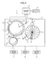
- FIG. 1 is a schematic configuration diagram of an example of the automatic analyzer of the present invention.
- FIG. 2 is a schematic configuration diagram of a wastewater suction device employed in the automatic analyzer of FIG. 1 .
- An automatic analyzer 1 includes, as shown in FIG. 1 , an operation table 2 on which a sample table 3, a reaction table 6, and a reagent table 11 are arranged separate from each other so that each can rotate in a circumferential direction and be positioned freely. Further, the automatic analyzer 1 includes a sample-dispensing arm 5 near the sample table 3 and the reaction table 6, and a reagent-dispensing arm 13 for dispensing a reagent near the reaction table 6 and the reagent table 11.
- the sample table 3 is rotated by a driving device 17 in a direction indicated by an arrow as shown in FIG. 1 .
- plural storage units 3a are arranged equiangularly along the circumferential direction.
- a sample vessel 4 holding a sample is detachably stored in each of the storage units 3a.
- the sample-dispensing arm 5 sequentially dispenses the samples in the plural sample vessels 4 on the sample table 3 into a reaction vessel 7.
- the reaction table 6 is rotated by a driving device 18 such as a pulse motor in a direction indicated by an arrow.
- a driving device 18 such as a pulse motor in a direction indicated by an arrow.
- the reaction vessel 7 is detachably stored in each storage unit 6a to cause reaction of the sample and the reagent.
- a light source 8 and a wastewater suction device 20 are arranged on the reaction table 6.
- the light source 8 emits analyzing light (of 340 nm to 800 nm) for analyzing a reaction liquid produced by the reaction of the reagent and the sample in the reaction vessel 7.
- the analyzing light emitted from the light source 8 transmits the reaction liquid in each reaction vessel 7 transferred by the reaction table 6 rotating in the direction indicated by the arrow, and is received by a light-receiving device 9 arranged opposite to the light source 8.
- the light-receiving device 9 is connected to a control device 15 which calculates components, concentration, and the like of the sample based on an absorbance of the reaction liquid in each reaction vessel 7.
- the reagent table 11 is rotated by a driving device 19 in a direction indicated by an arrow as shown in FIG. 1 .
- a driving device 19 On the reagent table 11, plural storage units 11a formed in a fan-like shape are arranged along a circumferential direction.
- a reagent vessel 12 is detachably stored in each storage unit 11a.
- the plural reagent vessels 12 are each filled with a predetermined reagent corresponding to a test item, and an information label is pasted onto an outer surface of the reagent vessel 12 to indicate information related to the stored reagent.
- a reader device 14 is arranged external to the outer circumference of the reagent table 11.
- the reader device 14 reads the information recorded in the information label pasted on the reagent vessel 12, such as a type, a lot, and an expiration date of the reagent, an identification number of the reagent vessel 12, and the like and outputs the read-out information to the control device 15.
- the control device 15 includes a control unit 15a, a vessel determination unit 15b, and a clog determination unit 15c.
- the control device 15 controls the operation of the automatic analyzer 1 based on information input by an input unit 16.
- the control unit 15a has a timer function, and controls the operations of the sample-dispensing arm 5, the light-receiving device 9, the reagent-dispensing arm 13, the reader device 14, the driving devices 17 to 19, and the wastewater suction device 20.
- the vessel determination unit 15b calculates components, concentration, and the like of the sample in the reaction vessel 7 based on optical signals output from the light-receiving device 9 concerning the amount of received light, and determines whether there is the reaction vessel 7 or not, and further associates with a position on the reaction table 6 for which the presence/absence of the reaction vessel 7 is detected based on pulse signals output from the driving device 18.
- the vessel determination unit 15b determines whether there is the reaction vessel 7 or not utilizing the above results, when the reaction vessel 7 is transferred to the position of the wastewater suction device 20 and the suction nozzle 21b is clogged.
- the clog determination unit 15c calculates rate of change ( ⁇ P/ ⁇ t) in pressure (P) based on a pressure signal output from a pressure sensor 23 for the suction nozzle 21b and determines whether each suction nozzle 21b is clogged or not based on the rate of change of pressure as calculated and the presence/absence of the reaction vessel 7 determined by the vessel determination unit 15b.
- the wastewater suction device 20 is arranged at a disposal position on the outer periphery of the reaction table 6. As shown in FIG. 2 , the wastewater suction device 20 includes a nozzle transfer unit 21, a wastewater tank 24, a vacuum tank 27, and a cleaning tank 29, and shares the control device 15 with the automatic analyzer 1.
- the nozzle transfer unit 21 supports plural suction nozzles 21b on a main body 21a and moves the plural suction nozzles 21b in an up-down direction and a horizontal direction under the control of the control device 15 so that the plural suction nozzles 21b are alternately transferred between the reaction table 6 and the cleaning tank 29.
- the wastewater tank 24 is connected to the respective suction nozzles 21b of the nozzle transfer unit 21 by pipes 22. Reaction wastewater suctioned by the plural suction nozzles 21b from the reaction vessel 7 and a cleaning liquid suctioned from the cleaning tank 29 are disposed in the wastewater tank 24.
- the pressure sensor 23 is arranged in each of the pipes 22 separately. Pressure (analog signal) detected by the pressure sensor 23 is converted into a digital pressure signal by an A/D converter 31 and output to the control device 15.
- the wastewater tank 24 is connected to a drain pipe 25 to which a drain valve 25a is attached.
- each of the pressure sensors 23 is arranged in the pipe 22 near the suction nozzle 21b and the pipes 22 guide negative pressure to the suction nozzle 21b for suction, the pressure sensor 23 can detect pressure variation in the suction nozzle 21b in real time, in other words, the pressure sensor 23 can detect the clog of each suction nozzle 21b in real time.
- the wastewater tank 24 can drain the wastewater through the drain pipe 25 by closing a suction valve 26a and opening the drain valve 25a and an air open valve 26b.
- the vacuum tank 27 is connected to the wastewater tank 24 by a pipe 26 to which the suction valve 26a is attached.
- the pipe 26 is branched in the middle, and the air open valve 26b is attached to a branched part. Further, the vacuum tank 27 is connected to a suction pump 28. Operations of the drain valve 25a, the suction valve 26a, the air open valve 26b, and the suction pump 28 are controlled by the control device 15. When the reaction wastewater and the cleaning liquid are suctioned, the drain valve 25a and the air open valve 26b are closed.
- the cleaning tank 29 is arranged near the reaction table 6, and stores a cleaning liquid for cleaning the plural suction nozzles 21b after the suction of the reaction wastewater.
- the suction pump 28 when the suction pump 28 is driven to render the pressure in the vacuum tank 27 negative and the suction valve 26a is opened for a predetermine period of time, the negative pressure in the vacuum tank 27 is guided through the wastewater tank 24 and the pipes 22 to the plural suction nozzles 21b. Therefore, when the suction nozzle 21b, which suctions the reaction wastewater in the reaction vessel 7, is not clogged, the pressure in the suction nozzle 21b suddenly becomes negative within a short period of time after the suction valve 26a is opened, and the suction nozzle 21b suctions the reaction wastewater. When the suction valve 26a is closed, the pressure in the suction nozzle 21b gradually increases and returns to the atmospheric pressure.
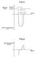
- the pressure sensor 23 Because the pressure sensor 23 is arranged near the suction nozzle 21b in the pipe 22, the pressure sensor 23 detects the pressure variation in the suction nozzle 21b in real time. Therefore, when the suction valve 26a is opened, the pressure signal input to the control device 15 based on the pressure detected by the pressure sensor 23 shows a waveform with a large peak value variation as shown in FIG. 3 . The rate of change of pressure calculated by the clog determination unit 15c based on the pressure signal shown in FIG. 3 exhibits large negative/positive variations as shown in FIG. 4 .
- the pressure in the suction nozzle 21b suddenly turns to a predetermined negative level within a short period of time after the suction valve 26a is opened.
- the suction valve 26a is closed, the pressure in the suction nozzle 21b gradually increases and returns suddenly to the atmospheric pressure when other suction nozzle 21b is communicated with the atmosphere. Therefore, the pressure signal input to the control device 15 based on the pressure detected in real time by the pressure sensor 23 shows a waveform with a little peak value variation as shown in FIG. 5 when valve-opening time of the suction valve 26a is the same.
- the rate of change of pressure calculated by the clog determination unit 15c shows a little negative/positive variation as shown in FIG. 6 in comparison with the time when the suction nozzle 21b is not clogged.
- the clog determination unit 15c adds to a factor for determination, the presence/absence of the reaction vessel 7 at the disposal position on the outer periphery of the reaction table 6, and determines whether each of the suction nozzles 21b is clogged or not based on the rate of change of pressure calculated by the clog determination unit 15c and the presence/absence of the reaction vessel 7 determined by the vessel determination unit 15b.
- the clog determination unit 15c distinguishes the waveform of FIG. 5 obtained when there is the reaction vessel 7 and the suction nozzle 21b is clogged from a waveform obtained when there is no reaction vessel 7 and the suction nozzle 21b suctions without effect.
- the vessel determination unit 15b determines whether there is reaction wastewater or not based on the optical signal output from the light-receiving device 9.
- the clog determination unit 15c distinguishes a case where there is the reaction vessel 7 though there is no reaction wastewater to suction from a case where there is no reaction vessel 7 and no reaction wastewater to suction based on the result of determination on the presence/absence of the reaction wastewater.
- the automatic analyzer 1 configured as described above sequentially dispenses the samples in the plural sample vessels 4 on the sample table 3 using the sample-dispensing arm 5 into the reaction vessel 7 transferred along the circumferential direction by the rotating reaction table 6.
- the reaction vessel 7 into which the sample is dispensed is transferred close to the reagent-dispensing arm 13 by the reaction table 6, and the reagent in a predetermined one of the reagent vessels 12 is dispensed. While the reaction vessel 7 into which the reagent is dispensed is transferred along the circumferential direction by the reaction table 6, the specimen and the reagent agitated and react with each other pass between the light source 8 and the light-receiving device 9.
- the reaction liquid in the reaction vessel 7 is subjected to photometry by the light-receiving device 9, and the control device 15 calculates the components, concentration, and the like of the reaction liquid based on the absorbance thereof. After the analysis is finished, the reaction vessel 7 is transferred to the disposal position.
- the wastewater suction device 20 drains the reaction wastewater after the reaction from the reaction vessel 7. Then, the reaction vessel 7 is cleaned by a cleaning device not shown, and used again for the analysis of the sample.
- the wastewater suction device 20 render the pressure in the vacuum tank 27 negative by driving the suction pump 28 under the control of the control device 15. Then, the wastewater suction device 20 transfers the nozzle transfer unit 21 to the disposal position on the outer periphery of the reaction table 6, lowers the nozzle transfer unit 21 so that the lower end of the plural suction nozzles 21b is inserted into the reaction wastewater in the plural reaction vessels 7 by a predetermined amount, and opens the suction valve 26a for a predetermined period of time.
- the reaction wastewater after the measurement finishes is suctioned by the plural suction nozzles 21b from the plural reaction vessels 7 and drained to the wastewater tank 24.
- the wastewater suction device 20 raises the nozzle transfer unit 21 under the control of the control device 15 while keeping the suction vale 26a closed, and moves the nozzle transfer unit 21 in the horizontal direction to above the cleaning tank 29. Then, the wastewater suction device 20 lower the nozzle transfer unit 21 under the control of the control device 15 so that the lower end of the plural suction nozzles 21b is inserted into the cleaning liquid by a predetermined amount, and makes the plural suction nozzles 21b suction the cleaning liquid stored in the cleaning tank 29 by opening the suction valve 26a for a predetermined period of time.
- the plural suction nozzles 21b are cleaned by the suctioned cleaning liquid, and the cleaning liquid after the cleaning is drained to the wastewater tank 24.
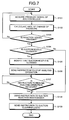
- the clog determination unit 15c determines whether each of the suction nozzles 21b is clogged or not based on the rate of change of pressure in the suction nozzle 21b as calculated and the presence/absence of the reaction vessel 7, as follows.
- the control device 15 firstly acquires the pressure signal of the suction nozzle 21b from each of the plural pressure sensors 23 (step S101). Then, the control device 15 calculates the rate of change ( ⁇ P/ ⁇ t) in pressure (P) based on the acquired pressure signal from each of the pressures sensors 23 (step S102).
- the control device 15 determines whether the reaction vessel 7 is present at the disposal position or not (step S103). The determination is performed by the vessel determination unit 15b based on the optical signal output from the light-receiving device 9. When it is determined that there is no reaction vessel 7 at the disposal position (No in step S103), the control device 15 returns to step S101 and acquires the pressure signal of the suction nozzle 21b. On the other hand, when the reaction vessel 7 is present at the disposal position (Yes in step S103), the control device 15 determines whether the suction nozzle 21b is clogged or not (step S104). The determination is made for each of the suction nozzles 21b based on the rate of change ( ⁇ P/ ⁇ t) in pressure calculated by the vessel determination unit 15b and the presence/absence of the reaction vessel 7 determined by the vessel determination unit 15b.
- step S104 When it is determined that the suction nozzle 21b is not clogged (No in step S104), the control device 15 skips to step S108. On the other hand, when the suction nozzle 21b is clogged (Yes in step S104), the control device 15 notifies that the suction nozzle 21b is clogged (step S105).
- the notification is realized by displaying a position (number) of the suction nozzle 21b which is clogged on a display of the automatic analyzer 1 or by raising an alarm along with the display, for example.
- control device 15 instructs the automatic analyzer 1 to stop the analysis operation (step S106). While the automatic analyzer 1 stops following the instruction, an operator exchanges the suction nozzle 21b which is clogged, or exchanges all of the plural suction nozzles 21b.
- the control device 15 determines whether an instruction to resume the analysis operation is given to the automatic analyzer 1 or not (step S107).
- the control device 15 determines again whether the instruction to resume the analysis operation is given or not (step S107).
- the control device 15 instructs the wastewater suction device 20 to suction the reaction wastewater from the reaction vessel 7 because the suction of the reaction wastewater has not been finished for some reaction vessels 7 because of the clogging of the suction nozzle 21b (step S108).
- the control device 15 instructs the wastewater suction device 20 to suction the cleaning liquid (step S109).
- the nozzle transfer unit 21 moves to the position of the cleaning tank 29 and suctions the cleaning liquid.
- the plural suction nozzles 21b are cleaned. Because the automatic analyzer 1 cleans the suction nozzles 21b by suctioning the cleaning liquid every time the suction nozzle 21b suctions the reaction wastewater, the clogging of the suction nozzles 21b, the pipes 22, and the pressure sensors 23 can be prevented from being caused by crystal generated through the reaction of the sample and the reagent.
- the clog determination unit 15c employs the rate of change ( ⁇ P/ ⁇ t) in pressure calculated by the vessel determination unit 15b on determining whether each of the suction nozzles 21b is clogged or not.
- the clog determination unit 15c may determine whether each of the suction nozzles 21b is clogged or not based on the presence/absence of the reaction vessel 7 and recovery time required for the pressure in the suction nozzle 21b to return to the atmospheric pressure after negative pressure is introduced into the suction nozzle 21b (time Tn in FIG. 3 , and time Tb in FIG. 5 ) utilizing the timer function of the control unit 15a.
- the clog determination unit 15c determines that the suction nozzle 21b is not clogged when the reaction vessel 7 is present at the disposal position and recovery time Tn is longer than predetermined reference value Tt, whereas determines that the suction nozzle 21b is clogged when recovery time Tb is shorter than the reference value Tt.
- the vessel determination unit 15b determines whether the reaction vessel 7 is present or not utilizing the optical signal output from the light-receiving device 9 without providing an additional detector.
- the vessel determination unit 15b can, however, utilize various types of elements, such as a contact and a sensor, as far as the vessel determination unit 15b can determine whether the reaction vessel 7 is present or not at the disposal position.
- reaction vessel may be, other than the reaction vessel 7 described in the above embodiment, a microplate.
- the automatic analyzer according to the present invention is useful for detecting in real time a clog in each of suction nozzles provided in a wastewater suction unit.
Landscapes
- Physics & Mathematics (AREA)
- Health & Medical Sciences (AREA)
- Life Sciences & Earth Sciences (AREA)
- Chemical & Material Sciences (AREA)
- Analytical Chemistry (AREA)
- Biochemistry (AREA)
- General Health & Medical Sciences (AREA)
- General Physics & Mathematics (AREA)
- Immunology (AREA)
- Pathology (AREA)
- Automatic Analysis And Handling Materials Therefor (AREA)
Applications Claiming Priority (2)
| Application Number | Priority Date | Filing Date | Title |
|---|---|---|---|
| JP2006132555 | 2006-05-11 | ||
| PCT/JP2007/058511 WO2007132630A1 (ja) | 2006-05-11 | 2007-04-19 | 自動分析装置 |
Publications (1)
| Publication Number | Publication Date |
|---|---|
| EP2017625A1 true EP2017625A1 (en) | 2009-01-21 |
Family
ID=38693730
Family Applications (1)
| Application Number | Title | Priority Date | Filing Date |
|---|---|---|---|
| EP07741947A Withdrawn EP2017625A1 (en) | 2006-05-11 | 2007-04-19 | Automatic analyzer |
Country Status (4)
| Country | Link |
|---|---|
| US (1) | US8088343B2 (ja) |
| EP (1) | EP2017625A1 (ja) |
| JP (1) | JP4949389B2 (ja) |
| WO (1) | WO2007132630A1 (ja) |
Cited By (1)
| Publication number | Priority date | Publication date | Assignee | Title |
|---|---|---|---|---|
| EP2482045A1 (de) * | 2011-01-28 | 2012-08-01 | Tecan Trading AG | Verfahren zum Erfassen der Befüllbarkeit eines Abfallbehälters von Mikroplatten-Waschgeräten |
Families Citing this family (14)
| Publication number | Priority date | Publication date | Assignee | Title |
|---|---|---|---|---|
| JP2010002237A (ja) * | 2008-06-18 | 2010-01-07 | Olympus Corp | ノズル詰まり検知方法および自動分析装置 |
| DE112010002270B4 (de) * | 2009-01-30 | 2013-10-17 | Hitachi High-Technologies Corporation | Automatischer Analysator und Probenbehandlungsvorrichtung |
| JP5124497B2 (ja) * | 2009-01-30 | 2013-01-23 | 株式会社日立ハイテクノロジーズ | 自動分析装置 |
| JP2012154917A (ja) * | 2011-01-05 | 2012-08-16 | Hitachi High-Technologies Corp | 固相抽出の異常判定方法、及び固相抽出装置 |
| EP2739979B1 (en) * | 2011-08-03 | 2019-01-16 | Becton, Dickinson and Company | Detection of a compromised flow line in a laboratory instrument |
| JP2013255447A (ja) * | 2012-06-12 | 2013-12-26 | Nippon Koden Corp | 細胞単離装置 |
| JP6018828B2 (ja) * | 2012-07-27 | 2016-11-02 | 株式会社日立ハイテクノロジーズ | 自動分析装置 |
| JP6609429B2 (ja) * | 2015-06-30 | 2019-11-20 | 日本光電工業株式会社 | 血液分析方法および血液分析装置 |
| JP6664977B2 (ja) * | 2016-01-28 | 2020-03-13 | キヤノンメディカルシステムズ株式会社 | 自動分析装置 |
| JP6749857B2 (ja) * | 2017-03-24 | 2020-09-02 | 株式会社日立ハイテク | 自動分析装置 |
| JP6785989B2 (ja) * | 2017-10-10 | 2020-11-18 | 株式会社日立ハイテク | 自動分析装置 |
| EP3677916B1 (en) * | 2018-01-26 | 2023-07-12 | Hitachi High-Tech Corporation | Automated analyzer |
| JP6877629B2 (ja) * | 2018-03-15 | 2021-05-26 | 株式会社日立ハイテク | 自動分析装置および自動分析装置の流路詰まり検出方法 |
| US11320295B2 (en) * | 2019-04-26 | 2022-05-03 | Festo Se & Co. Kg | Dosing unit and method for dosing a liquid |
Family Cites Families (10)
| Publication number | Priority date | Publication date | Assignee | Title |
|---|---|---|---|---|
| JPH049734A (ja) * | 1990-04-27 | 1992-01-14 | Shimadzu Corp | 液体試料分注装置 |
| JP2784694B2 (ja) | 1990-12-27 | 1998-08-06 | 日本電子株式会社 | 自動化学分析装置 |
| JP3283089B2 (ja) * | 1993-03-16 | 2002-05-20 | オリンパス光学工業株式会社 | 容器洗浄装置 |
| AU4982093A (en) * | 1993-08-31 | 1995-03-22 | Abbott Laboratories | Pipetting apparatus equipped with closure detection function |
| JPH10246690A (ja) * | 1997-02-28 | 1998-09-14 | Shimadzu Corp | 試料導入装置 |
| EP0918221B1 (en) * | 1997-11-19 | 2006-09-06 | Grifols, S.A. | Apparatus for performing laboratory tests automatically |
| AUPP058197A0 (en) * | 1997-11-27 | 1997-12-18 | A.I. Scientific Pty Ltd | Pathology sample tube distributor |
| JP3700402B2 (ja) * | 1998-07-24 | 2005-09-28 | 富士レビオ株式会社 | 吸引流路の詰まりまたは吸引量不足の検出方法、試料液吸引装置、及び分注装置 |
| JP2004325117A (ja) * | 2003-04-22 | 2004-11-18 | Olympus Corp | 液体分注装置および分注ヘッドの洗浄方法 |
| JP2005201784A (ja) * | 2004-01-16 | 2005-07-28 | Sysmex Corp | 分注装置およびそれを備えた分析装置ならびに液体の吸引または吐出の異常判定方法 |
-
2007
- 2007-04-19 WO PCT/JP2007/058511 patent/WO2007132630A1/ja active Application Filing
- 2007-04-19 JP JP2008515468A patent/JP4949389B2/ja not_active Expired - Fee Related
- 2007-04-19 EP EP07741947A patent/EP2017625A1/en not_active Withdrawn
-
2008
- 2008-10-10 US US12/249,432 patent/US8088343B2/en not_active Expired - Fee Related
Non-Patent Citations (1)
| Title |
|---|
| See references of WO2007132630A1 * |
Cited By (2)
| Publication number | Priority date | Publication date | Assignee | Title |
|---|---|---|---|---|
| EP2482045A1 (de) * | 2011-01-28 | 2012-08-01 | Tecan Trading AG | Verfahren zum Erfassen der Befüllbarkeit eines Abfallbehälters von Mikroplatten-Waschgeräten |
| US8800365B2 (en) | 2011-01-28 | 2014-08-12 | Tecan Trading Ag | Method for registering the filling potential of a waste container of microplate washing devices |
Also Published As
| Publication number | Publication date |
|---|---|
| JP4949389B2 (ja) | 2012-06-06 |
| US20090041628A1 (en) | 2009-02-12 |
| WO2007132630A1 (ja) | 2007-11-22 |
| US8088343B2 (en) | 2012-01-03 |
| JPWO2007132630A1 (ja) | 2009-09-24 |
Similar Documents
| Publication | Publication Date | Title |
|---|---|---|
| EP2017625A1 (en) | Automatic analyzer | |
| EP2157435B1 (en) | Nozzle cleaning method, nozzle cleaning device, and automatic analyzer | |
| US9599631B2 (en) | Automatic analyzer | |
| US7803626B2 (en) | Automatic analyzer and method for determining abnormality in dispensing of dispensing system | |
| JPH03214058A (ja) | 自動分注希釈装置 | |
| US9207250B2 (en) | Reagent preparing device, reagent preparing method and specimen processing system | |
| US9513305B2 (en) | Multiple cleaning stations for a dispensing probe | |
| JP2012189586A (ja) | 自動分析装置 | |
| EP2019321A1 (en) | Cleaning equipment and automatic analyzer | |
| JP2010210596A (ja) | 自動分析装置およびプローブ洗浄方法 | |
| JP2011522232A (ja) | 生物学的試料を装填及び識別するユニット並びにそのユニットを含む統合型装置 | |
| US11079402B2 (en) | Automatic analyzing apparatus, and method for detecting flow path clogging of the automatic analyzing apparatus | |
| JP2011106828A (ja) | 分注装置、自動分析装置及び分注方法 | |
| JP5912787B2 (ja) | 自動分析装置 | |
| JP3120180U (ja) | 自動分析装置 | |
| JP6121743B2 (ja) | 自動分析装置 | |
| WO2009148013A1 (ja) | 検体分注装置のプローブ洗浄方法、検体分注装置及び自動分析装置 | |
| JP2001305145A (ja) | 自動分析装置 | |
| JP6338898B2 (ja) | 自動分析装置 | |
| JP4576340B2 (ja) | 自動分析装置 | |
| JP2011007568A (ja) | 自動分析装置 | |
| JP2016090526A (ja) | 自動分析装置 | |
| JP2012189514A (ja) | 自動分析装置 | |
| JPH03285168A (ja) | 試料分注装置 | |
| KR20110118249A (ko) | 평행이동 면역크로마토그래피를 이용한 생체물질의 정밀 분석 장치 |
Legal Events
| Date | Code | Title | Description |
|---|---|---|---|
| PUAI | Public reference made under article 153(3) epc to a published international application that has entered the european phase |
Free format text: ORIGINAL CODE: 0009012 |
|
| 17P | Request for examination filed |
Effective date: 20081010 |
|
| AK | Designated contracting states |
Kind code of ref document: A1 Designated state(s): AT BE BG CH CY CZ DE DK EE ES FI FR GB GR HU IE IS IT LI LT LU LV MC MT NL PL PT RO SE SI SK TR |
|
| AX | Request for extension of the european patent |
Extension state: AL BA HR MK RS |
|
| RBV | Designated contracting states (corrected) |
Designated state(s): DE FR GB |
|
| RAP1 | Party data changed (applicant data changed or rights of an application transferred) |
Owner name: BECKMAN COULTER, INC. |
|
| RAP1 | Party data changed (applicant data changed or rights of an application transferred) |
Owner name: BECKMAN COULTER, INC. |
|
| DAX | Request for extension of the european patent (deleted) | ||
| STAA | Information on the status of an ep patent application or granted ep patent |
Free format text: STATUS: THE APPLICATION HAS BEEN WITHDRAWN |
|
| 18W | Application withdrawn |
Effective date: 20150518 |