EP2017203A2 - Druckmedienzufuhreinheit und Bilderzeugungsvorrichtung damit - Google Patents
Druckmedienzufuhreinheit und Bilderzeugungsvorrichtung damit Download PDFInfo
- Publication number
- EP2017203A2 EP2017203A2 EP08160547A EP08160547A EP2017203A2 EP 2017203 A2 EP2017203 A2 EP 2017203A2 EP 08160547 A EP08160547 A EP 08160547A EP 08160547 A EP08160547 A EP 08160547A EP 2017203 A2 EP2017203 A2 EP 2017203A2
- Authority
- EP
- European Patent Office
- Prior art keywords
- printing medium
- loading plate
- external force
- unit
- medium loading
- Prior art date
- Legal status (The legal status is an assumption and is not a legal conclusion. Google has not performed a legal analysis and makes no representation as to the accuracy of the status listed.)
- Withdrawn
Links
Images


Classifications
-
- G—PHYSICS
- G03—PHOTOGRAPHY; CINEMATOGRAPHY; ANALOGOUS TECHNIQUES USING WAVES OTHER THAN OPTICAL WAVES; ELECTROGRAPHY; HOLOGRAPHY
- G03G—ELECTROGRAPHY; ELECTROPHOTOGRAPHY; MAGNETOGRAPHY
- G03G15/00—Apparatus for electrographic processes using a charge pattern
-
- B—PERFORMING OPERATIONS; TRANSPORTING
- B65—CONVEYING; PACKING; STORING; HANDLING THIN OR FILAMENTARY MATERIAL
- B65H—HANDLING THIN OR FILAMENTARY MATERIAL, e.g. SHEETS, WEBS, CABLES
- B65H3/00—Separating articles from piles
- B65H3/02—Separating articles from piles using friction forces between articles and separator
- B65H3/06—Rollers or like rotary separators
- B65H3/0607—Rollers or like rotary separators cooperating with means for automatically separating the pile from roller or rotary separator after a separation step
-
- B—PERFORMING OPERATIONS; TRANSPORTING
- B65—CONVEYING; PACKING; STORING; HANDLING THIN OR FILAMENTARY MATERIAL
- B65H—HANDLING THIN OR FILAMENTARY MATERIAL, e.g. SHEETS, WEBS, CABLES
- B65H2403/00—Power transmission; Driving means
- B65H2403/50—Driving mechanisms
- B65H2403/51—Cam mechanisms
-
- B—PERFORMING OPERATIONS; TRANSPORTING
- B65—CONVEYING; PACKING; STORING; HANDLING THIN OR FILAMENTARY MATERIAL
- B65H—HANDLING THIN OR FILAMENTARY MATERIAL, e.g. SHEETS, WEBS, CABLES
- B65H2511/00—Dimensions; Position; Numbers; Identification; Occurrences
- B65H2511/10—Size; Dimensions
- B65H2511/15—Height, e.g. of stack
-
- B—PERFORMING OPERATIONS; TRANSPORTING
- B65—CONVEYING; PACKING; STORING; HANDLING THIN OR FILAMENTARY MATERIAL
- B65H—HANDLING THIN OR FILAMENTARY MATERIAL, e.g. SHEETS, WEBS, CABLES
- B65H2511/00—Dimensions; Position; Numbers; Identification; Occurrences
- B65H2511/20—Location in space
- B65H2511/22—Distance
- B65H2511/222—Stroke
-
- B—PERFORMING OPERATIONS; TRANSPORTING
- B65—CONVEYING; PACKING; STORING; HANDLING THIN OR FILAMENTARY MATERIAL
- B65H—HANDLING THIN OR FILAMENTARY MATERIAL, e.g. SHEETS, WEBS, CABLES
- B65H2801/00—Application field
- B65H2801/03—Image reproduction devices
- B65H2801/06—Office-type machines, e.g. photocopiers
Definitions
- the present disclosure relates to a printing medium supplying unit and an image forming apparatus having the same and, more particularly, to a printing medium supplying unit capable of adjusting the height of a printing medium loading component.
- An image forming apparatus includes a printing medium supplying unit, an image forming unit, and a discharging unit.
- the printing medium supplying unit may be configured to supplying the printing medium to an image forming unit.
- This printing medium may include, for example, paper, transparent sheets, cardboard, or any other material on which an image may be formed.
- the image forming unit may be configured to forming an image on the printing medium.
- This image forming unit may include, for example, a photoreceptor.
- the photoreceptor may be in the form of a drum assembly made of photoconductive material on which a representation of an image can be formed by light.
- the image forming unit may form the image on the printing medium supplied from the printing medium supplying unit.
- the discharging unit may be configured to discharge the printing medium to an external unit once the image is formed on the printing medium.
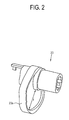
- FIGs. 1A and 1B are perspective views illustrating an operation of a conventional printing medium supplying unit 10.
- the conventional printing medium supplying unit 10 includes a feeding cassette 30, a printing medium loading plate 31, a pickup roller 20, and a cam member 23.
- the printing medium loading plate 31 moves up and down inside the feeding cassette 30 and allows a printing medium to be loaded thereon.
- the pickup roller 20 picks up the printing medium from the printing medium loading plate 31.
- the cam member 23 is coaxially located with a rotation shaft 21 of the pickup roller 20.
- the cam member 23 is configured to press or release the printing medium loading plate 31 so as to move the printing medium loading plate 31 down or up, respectively.
- FIG. 1A if a printing signal is not applied, the cam member 23 presses the printing medium loading plate 31 to separate the pickup roller 20 from the printing medium.
- FIG. 1B if the printing signal is applied, the rotation shaft 21 rotates and the pressure applied against the printing medium loading plate 31 is withdrawn. Accordingly, the printing medium loading plate 31 moves up toward the pickup roller 20. The pickup roller 20 then picks up the printing medium and transfers the printing medium toward an image forming unit (not shown). Once the pickup roller 20 has picked up the printing medium, the cam member 23 once again presses the printing medium loading plate 31 to move the printing medium loading plate 31 down.
- the conventional printing medium supplying unit 10 may be used to provide a printing medium to an image forming unit, the unit 10 suffers from various shortcomings.
- a length 1 of a cam profile 23a is uniform along an axial line of the rotation shaft 21.
- This uniform length 1 of the cam profile 23a causes the height at which the printing medium loading plate 31 is maintained to be uniform irrespective of the amount of the printing medium loaded on the printing medium loading plate 31. Accordingly, if the amount of the printing medium loaded on the printing medium loading plate 31 is reduced, the speed of elevation of the printing medium loading plate 31 released from the pressing force increases.
- This increase in the elevation speed of the printing medium loading plate 31 may cause a loud noise upon impact when the printing medium loading plate 31 comes in contact with the pickup roller 20.
- This impact noise is one of the noises most often heard when using an image forming apparatus that includes the conventional printing medium supplying unit 10.
- the contact area 33 of the printing medium loading plate 31 that comes in contact with the cam member 23 may be damaged due to the impact.
- the present disclosure is directed towards overcoming one or more shortcomings of the conventional printing medium supplying unit 10.
- the unit comprises a printing medium loading plate configured to move up and down, and on which an amount of printing medium may be loaded and an elevation control unit configured to adjust an elevation height of the printing medium loading plate to vary a standby position of the printing medium loading plate based on the amount of the printing medium loaded on the printing medium loading plate, wherein the standby position of the printing medium loading plate is a position of the printing medium loading plate when the printing medium is not being supplied from the printing medium supplying unit.
- the apparatus comprises a printing medium supplying unit.
- the printing medium supplying unit comprises a printing medium loading plate configured to move up and down , and on which an amount of printing medium may be loaded and an elevation control unit configured to adjust an elevation height of the printing medium loading plate to vary a standby position of the printing medium loading plate based on the amount of the printing medium loaded on the printing medium loading plate, wherein the standby position of the printing medium loading plate is a position of the printing medium loading plate when the printing medium to an image forming unit.
- the apparatus also comprises an image forming unit configured to form an image on a printing medium supplied from the printing medium supplying unit and a printing medium discharging unit configured to discharge the printing medium on which the image is formed.
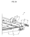
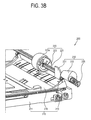
- FIGs. 3A and 3B are perspective views illustrating a configuration of a printing medium supplying unit 200 according to an exemplary disclosed embodiment.
- the printing medium supplying unit 200 includes a cassette unit 210, a pickup unit 220, and an elevation control unit 230.
- the cassette unit 210 accommodates a printing medium loading plate 215 in which a printing medium is loaded.
- the pickup unit 220 picks up the printing medium loaded in the printing medium loading plate 215 and provides the picked up printing medium to an image forming unit.
- the elevation control unit 230 adjusts an elevation height of the printing medium loading plate 215. This elevation height may be adjusted depending on the amount of printing medium loaded in the printing medium loading plate 215. Furthermore, the elevation height is adjusted so that the pickup unit 220 can pick up the printing medium.
- the cassette unit 210 includes a cassette main body 211.
- the main body 211 accommodates the printing medium that is loaded on the printing medium loading plate 215.
- the printing medium loading plate 215 is configured to move up and down between a standby position and a supply position inside the cassette main body 211.
- the printing medium loading plate 215 includes an upper surface on which the printing medium is loaded.
- the cassette unit 210 also includes an elevation adjusting elastic member (not shown) provided between the printing medium loading plate 215 and the cassette main body 211.
- the elevation adjusting elastic member may be configured to supply an elastic force to raise the printing medium loading plate 215 to a supply position to supply the printing medium to the pickup unit 220.
- the printing medium loading plate 215 is provided to move up and down between a standby position and a supply position.
- the standby position is one in which the printing medium loading plate 215 is distanced from a pickup roller 223.
- the supply position is one in which the printing medium loading plate 215 moves up to the pickup roller 223 so that the printing medium can come in contact with the pickup roller 223.
- a side of the printing medium loading plate 215 is provided with a contact member 213 that protrudes from a bottom surface.
- the contact member 213 may be configured to come in contact with and be separated from an external force receiving unit 233 (as shown in FIG. 4 ).
- the contact member 213 may beneficially include an idle roller driven by rotation of the external force receiving unit 233.
- the printing medium loading plate 215 moves down toward the cassette main body 211 so that the printing medium loaded in the printing medium loading plate 215 is not in contact with the pickup roller 223.
- the printing medium loading plate 215 moves up so that the printing medium loaded in the printing medium loading plate 215 can be in contact with the pickup roller 223.
- the height by which the printing medium loading plate 215 moves up and down is the difference between the height of a printing medium positioned in the top in the standby position, and the height which the top-positioned printing medium has in the supply position.
- the elevation adjusting elastic member 217 is provided between the cassette main body 211 and the printing medium loading plate 215.
- the elevation adjusting elastic member 217 may be configured to apply an elastic force such that the printing medium loading plate 215 moves up.
- the elevation adjusting elastic member 217 is forced down by the weight of the printing medium loaded in the printing medium loading plate 215.
- the elevating adjusting elastic member 217 may be provided as a coil spring (as shown), a leaf spring, or the like.
- the pickup unit 220 may be configured to pick up the printing medium from the printing medium loading plate 215 when the printing medium loading plate 215 moves up to the supply position.
- the pickup unit 220 may include a rotation shaft 221 and a pickup roller 223.
- the rotation shaft 221 may rotate based on an input of a control signal.
- a pickup gear (not shown) may drive the rotation shaft.
- the pickup roller 223 may be coupled to the rotation shaft 221 to pick up the printing medium.
- the rotation shaft 221 may be provided to be coaxial with the pickup gear to rotate together with the pickup gear when a driving force is transmitted to the pickup gear.
- the pickup roller is in contact with a solenoid (not shown), and receives a signal from the solenoid to rotate according to a printing signal applied from a control unit (not shown).
- the pickup roller 223 rotates in contact with the top-positioned printing medium loaded in the printing medium loading plate 215. By rotating in contact with the top-positioned printing medium, a frictional force is generated between the pickup roller 223 and the top-positioned printing medium. This frictional force may be used to transfer the top-positioned printing medium from the printing medium loading plate 215 to the pickup roller 223.
- the pickup roller 223 includes an elastic layer 223a formed of a material such as, for example, rubber, having a big friction force.
- the elevation control unit 230 adjusts the height of the standby position of the printing medium loading plate 215 based on the amount of printing medium loaded on the printing medium loading plate 215.
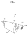
- the elevation control unit 230 includes an external force receiving unit 233, a pressing elastic member 235, and an external force applying unit 231.
- the external force receiving unit 233 is slidably provided to the rotation shaft 221 of the pickup roller 223.
- the pressing elastic member 235 elastically presses the external force receiving unit 233 and the external force applying unit 231 coupled to the printing medium loading plate 215. This pressure applied by the pressing elastic member 235 forces the external force receiving unit 233 in a resisting direction against an elastic force of the pressing elastic member 235.
- the external force receiving unit 233 includes an external force receiving main body 233a in contact with the external force applying unit 231, a shaft coupling member 233c extending from the external force receiving main body 233a to be coupled to the rotation shaft 221, and an elastic member coupling unit 233d to which the pressing elastic member 235 is coupled.
- the external force receiving main body 233a includes an elevation profile 233b.
- This elevation profile 233b is provided to the rotation shaft 221 and has a varying maximum diameter R that is in contact with the contact member 213. That is, a contact radius of the external force receiving main body 233a varies according to the direction of the rotation shaft 221, and the diameter of the rotation shaft 221.
- the radius R of the elevating profile 233b may decrease continuously from an outer side of the rotation shaft 221 to an inner side.
- the radius R of the elevating profile 233b may decrease discontinuously. For example, the radius R may decrease in steps instead of decreasing continuously.
- the radius R of the external force receiving main body 233a may determine the standby position of the printing medium loading plate 215.
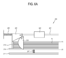
- the standby position of the printing medium loading plate 215 is determined depending on a contact position of the elevation profile 233b with the contact member 213. Accordingly, the elevation height of the printing medium loading plate 215 is determined based on the contact position of the elevation profile 233b with the contact member 213. That is, as shown in FIG. 6A , if the radius R of the elevating profile 233b is maximum, the standby position of the printing medium loading plate 215 is provided to a position adjacent to the cassette main body 211. On the other hand, as shown in FIG.
- the external force receiving main body 233a is provided to slide on the rotation shaft 221. Furthermore, a rotation shaft accommodating hole 233e is formed through the external force receiving main body 233a.
- the rotation shaft accommodating hole 233a has an inner diameter bigger than a diameter of the rotation shaft 221. As shown in FIG. 5 , the external force receiving main body 233a moves horizontally along the rotation shaft 221 based on the interplay between the external force applying unit 231 and the pressing elastic member 235.
- the pressing elastic member 235 applies an elastic force to the external force receiving unit 233 so that an increasing area of the external force receiving main body 233a can come in contact with the contact member 213. That is, as shown in FIG. 5 , the pressing elastic member 235 applies an elastic force so that the external force receiving unit 233 can move toward the external force applying unit 231. As discussed above, the external force applying unit 231 is pressed by the external force receiving unit. Consequently, the external force applying unit 231 applies a reactionary external force to the external force receiving unit 233. Upon receiving such a force from the external force applying unit 231, the external force receiving unit 233 presses the printing medium loading plate 215.
- the external force applying unit 231 may be provided as an adjusting cam that presses in contact with the external force receiving unit 233.
- the external force applying unit 231 may be a solenoid that adjusts the position of the external force receiving unit 233 based on receipt of a control signal.
- the external force applying unit 231 may be an adjusting cam.
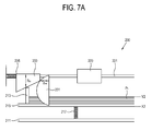
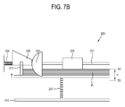
- the external force applying unit 231 includes an adjusting profile 231a.
- the adjusting profile 231a is shaped such that the distance between the line RL and the external force receiving unit 233 varies along the length of line RL.
- the external force receiving unit 233 is fixedly coupled to the printing medium loading plate 215 to move up and down together with the printing medium loading plate 215, which moves up and down between the standby position and the supply position.
- the distance between line RL and the external force receiving unit 233 may increase moving from the upper portion of the external force applying unit 231 towards the middle portion of the external force applying unit (d1>d2).
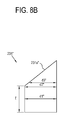
- the external force applying unit 231' may be shaped differently to have a different adjusting profile 231a'. Specifically, as shown in FIG. 8A , the distance between line RL and the external force receiving unit 233 may decrease and become smaller from a lower part to an upper part (d1'>d2').
- the pressing elastic member 235 causes the external force receiving unit 233 to come in contact with the external force applying unit 233. Furthermore, the contact length d of the external force applying unit 233 determines the horizontal distance the external force receiving unit 233 moves when the external force receiving unit 233 is in contact with the external force applying unit 231. The distance the external force receiving unit 233 moves determines the contact position of the external force receiving unit 233 with the printing medium loading plate 215. Additionally, as already discussed above, the radius R of the elevation profile 233b of the external force receiving main body varies along the length of the external force receiving unit 233. This variation in the radius R coupled with the distance the external force receiving unit 233 actually moves determines the amount by which the printing medium loading plate 215 is actually pressed.
- FIG. 6A An operating process of the printing medium supplying unit 200 according to an exemplary disclosed embodiment will now be described by referring to FIGs. 3A to 7B .
- the elevation adjusting elastic member 217 contracts due to the weight of the printing medium. This contraction of the elevation adjusting elastic member 217 causes the printing medium loading plate 215 to move down towards the cassette main body 211.
- the external force receiving unit 233 comes in contact with an upper part of the external force applying unit 231. Specifically, the external force receiving unit 233 is in contact with the adjusting profile 231a having a short contact length d. Furthermore, the pressing elastic member 235 exerts an elastic force to cause the external force applying unit 231 to move towards the pickup roller 223. Also, the contact member 213 comes in contact with a point of the external force receiving unit 233 having a big contact radius R. Accordingly, the standby position of the printing medium loading plate 215 is a position X adjacent to the cassette main body 211, and the height of the top-positioned printing medium is a position Y.
- the rotation shaft 221 rotates, the external force receiving unit 233 rotates together with the rotation shaft 221, and a pressing force pressing the contact member 213 is withdrawn.
- the printing medium loading plate 215 elastically moves up depending on the withdrawal of the pressing force.
- the supply position of the printing medium loading plate 215 becomes a position Y1'.
- the top-positioned printing medium comes in contact with the pickup roller 223.
- the elevation height of the printing medium loading plate 215 becomes a height difference h1 of the top-positioned printing medium.
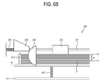
- the printing medium loading plate 215 has a relatively high standby position (X2>X1). That is, the contact length dm of the external force applying unit 231 pressing the external force receiving unit 233 toward the pressing elastic member 235 becomes bigger (dm>df) than the case shown in FIG. 6A as the height of the printing medium loading plate 215 increases. This increase in contact length dm pressing the external force receiving unit 233 causes the external force receiving unit 233 to move towards the pressing elastic member 235.
- This movement of the external force receiving unit 233 towards the pressing elastic member 235 causes the contact diameter Rm of the elevation profile 233b of the external force receiving unit 233 that presses the contact member 213 to become shorter (Rm ⁇ Rf) than the case shown in FIG. 6A . Because the contact diameter Rm becomes shorter, the height of the standby position of the printing medium loading plate 215 can increase (X2>X1).
- the rotation shaft 221 rotates, and the pressing force of the external force receiving unit 233 pressing the contact member 213 is withdrawn.
- the printing medium loading plate 215 moves up to the supply position in which the top-positioned printing medium comes in contact with the pickup roller 223.
- the elevation height of the printing medium loading plate 215 becomes smaller than the case shown in FIG. 6B , in which a large number of printing mediums are loaded.
- the elevating height of the top positioned printing medium loading plate 215 is substantially the same as the case shown in FIG. 6B (h1 h2).
- the elevation height of the top positioned printing medium can be maintained to be the substantially same.
- an impact noise can be uniform.
- the top-positioned printing medium moves up and down by the same distance as would be the case where the elevation height was the least, (i.e., a lot of printing mediums are loaded), the generated impact noise can be minimized.
- the standby position and the supply position of the printing medium loading plate 215 vary depending on the loading amount of the printing medium. Specifically, these positions are maintained when the elastic force of the elevating adjusting elastic member 217 elastically supporting the printing medium loading plate 215 and the elastic force of the pressing elastic member 235 balance each other. Accordingly, in designing the printing medium supplying unit 200, the elastic forces of the elevating adjusting elastic member 217 and the pressing elastic member 235 may be determined based on factors such as, for example, the shapes of the elevating profile 233b and the adjusting profile 231a and a maximum loading amount of the printing medium loaded in the printing medium loading plate 215.
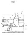
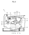
- FIG. 9 is a schematic view illustrating a configuration of an image forming apparatus 100 including the printing medium supplying unit 200 according to an exemplary disclosed embodiment.
- the image forming apparatus 100 includes the printing medium supplying unit 200, an image forming unit 300, a fusing unit 400, and a discharging unit 500.
- the image forming unit is configured to form an image on a printing medium.
- the fusing unit 400 is configured to fuse the image on the printing medium.
- the discharging unit 500 is configured to discharge the printing medium on which the image is completely formed to the outside.
- the image forming unit 300 applies a developer to the printing medium picked up by the pickup roller 223 to form an image.
- the fusing unit 400 applies heat and pressure to the printing medium to fuse the developer on the printing medium.
- the discharging unit 500 discharges the printing medium passing through the fusing unit 400 to an external unit that is configured to receive the printing medium with the image formed on the printing medium.
- the printing medium supplying unit may be mounted below the image forming apparatus.
- the disclosed printing medium supplying unit may be provided to a large sized printing apparatus that is commonly used to print advertising material, wall paper, etc.
- the present disclosure provides a printing medium supplying unit and an image forming apparatus having the same, that is capable of gradually raising a standby position of a printing medium loading plate as a loading amount of a printing medium decreases.
- This gradual raising of the standby position of the printing medium loading plate may help maintain an elevation height of the printing medium loading plate to be uniform. This operation may also help reduce an impact noise and/or impact damage generated when the printing medium is supplied to the image forming unit.
Landscapes
- Engineering & Computer Science (AREA)
- Mechanical Engineering (AREA)
- Physics & Mathematics (AREA)
- General Physics & Mathematics (AREA)
- Sheets, Magazines, And Separation Thereof (AREA)
Applications Claiming Priority (1)
| Application Number | Priority Date | Filing Date | Title |
|---|---|---|---|
| KR1020070073030A KR101172394B1 (ko) | 2007-07-20 | 2007-07-20 | 인쇄매체공급유닛 및 이를 포함하는 화상형성장치 |
Publications (2)
| Publication Number | Publication Date |
|---|---|
| EP2017203A2 true EP2017203A2 (de) | 2009-01-21 |
| EP2017203A3 EP2017203A3 (de) | 2011-01-05 |
Family
ID=39926751
Family Applications (1)
| Application Number | Title | Priority Date | Filing Date |
|---|---|---|---|
| EP08160547A Withdrawn EP2017203A3 (de) | 2007-07-20 | 2008-07-16 | Druckmedienzufuhreinheit und Bilderzeugungsvorrichtung damit |
Country Status (5)
| Country | Link |
|---|---|
| US (1) | US8116673B2 (de) |
| EP (1) | EP2017203A3 (de) |
| JP (1) | JP2009023842A (de) |
| KR (1) | KR101172394B1 (de) |
| CN (1) | CN101349880B (de) |
Cited By (1)
| Publication number | Priority date | Publication date | Assignee | Title |
|---|---|---|---|---|
| WO2011001660A3 (en) * | 2009-06-30 | 2011-08-25 | Canon Kabushiki Kaisha | Feeding apparatus and recording apparatus |
Families Citing this family (1)
| Publication number | Priority date | Publication date | Assignee | Title |
|---|---|---|---|---|
| JP5509761B2 (ja) * | 2009-09-18 | 2014-06-04 | 富士ゼロックス株式会社 | 搬送装置及び画像形成装置 |
Citations (1)
| Publication number | Priority date | Publication date | Assignee | Title |
|---|---|---|---|---|
| EP1681252A1 (de) | 2001-08-31 | 2006-07-19 | Seiko Epson Corporation | Aufzeichnungsvorrichtung |
Family Cites Families (12)
| Publication number | Priority date | Publication date | Assignee | Title |
|---|---|---|---|---|
| JPS55135033A (en) * | 1979-04-09 | 1980-10-21 | Ricoh Co Ltd | Sheet feeder |
| US4319740A (en) * | 1980-06-23 | 1982-03-16 | Minnesota Mining And Manufacturing Company | Sheet feeder |
| JPH0485217A (ja) * | 1990-07-25 | 1992-03-18 | Nec Corp | 給紙装置 |
| JP3403073B2 (ja) * | 1997-08-26 | 2003-05-06 | キヤノン株式会社 | シート給送装置及び画像処理装置 |
| JP2001026327A (ja) * | 1999-07-16 | 2001-01-30 | Ricoh Co Ltd | 給紙装置 |
| CH693335A5 (fr) * | 1999-08-09 | 2003-06-13 | Olivetti Tecnost | Dispositif d'introduction de matériauxplats. |
| JP2003182862A (ja) * | 2001-12-21 | 2003-07-03 | Canon Inc | シート給送装置、及びこれを備えた画像形成装置 |
| KR100605171B1 (ko) * | 2004-04-27 | 2006-07-31 | 삼성전자주식회사 | 화상형성장치의 급지장치 및 그 제어방법 |
| KR100561441B1 (ko) * | 2004-08-09 | 2006-03-17 | 삼성전자주식회사 | 용지픽업장치 및 이를 구비한 화상형성장치 |
| JP4006432B2 (ja) * | 2004-11-12 | 2007-11-14 | キヤノン株式会社 | シート給送装置及び画像形成装置 |
| JP2006240859A (ja) * | 2005-03-07 | 2006-09-14 | Kyocera Mita Corp | 給紙装置 |
| JP2006312542A (ja) * | 2005-05-09 | 2006-11-16 | Canon Inc | シート給送装置及び画像形成装置 |
-
2007
- 2007-07-20 KR KR1020070073030A patent/KR101172394B1/ko not_active Expired - Fee Related
-
2008
- 2008-05-21 US US12/124,350 patent/US8116673B2/en not_active Expired - Fee Related
- 2008-07-16 EP EP08160547A patent/EP2017203A3/de not_active Withdrawn
- 2008-07-18 JP JP2008187608A patent/JP2009023842A/ja active Pending
- 2008-07-18 CN CN200810133978XA patent/CN101349880B/zh not_active Expired - Fee Related
Patent Citations (1)
| Publication number | Priority date | Publication date | Assignee | Title |
|---|---|---|---|---|
| EP1681252A1 (de) | 2001-08-31 | 2006-07-19 | Seiko Epson Corporation | Aufzeichnungsvorrichtung |
Cited By (2)
| Publication number | Priority date | Publication date | Assignee | Title |
|---|---|---|---|---|
| WO2011001660A3 (en) * | 2009-06-30 | 2011-08-25 | Canon Kabushiki Kaisha | Feeding apparatus and recording apparatus |
| US8764158B2 (en) | 2009-06-30 | 2014-07-01 | Canon Kabushiki Kaisha | Feeding apparatus and recording apparatus |
Also Published As
| Publication number | Publication date |
|---|---|
| US8116673B2 (en) | 2012-02-14 |
| JP2009023842A (ja) | 2009-02-05 |
| KR101172394B1 (ko) | 2012-08-08 |
| US20090022537A1 (en) | 2009-01-22 |
| CN101349880A (zh) | 2009-01-21 |
| EP2017203A3 (de) | 2011-01-05 |
| KR20090009604A (ko) | 2009-01-23 |
| CN101349880B (zh) | 2013-02-13 |
Similar Documents
| Publication | Publication Date | Title |
|---|---|---|
| US7673872B2 (en) | Sheet feeding unit and image forming apparatus having the same | |
| US20080309004A1 (en) | Paper supply apparatus for a printing device | |
| US7481423B2 (en) | Print medium feeding apparatus and image forming apparatus using the same | |
| KR20050019416A (ko) | 인쇄기기의 급지장치 | |
| KR102047904B1 (ko) | 인쇄매체공급장치 및 이를 갖는 화상형성장치 | |
| EP2017203A2 (de) | Druckmedienzufuhreinheit und Bilderzeugungsvorrichtung damit | |
| US7681878B2 (en) | Paper feeding unit and image forming apparatus having the same | |
| US7543814B2 (en) | Automatic paper feeding apparatus | |
| US20060033258A1 (en) | Paper picking-up unit and image forming apparatus having the same | |
| US20040251612A1 (en) | Paper cassette for printing apparatus | |
| KR200233153Y1 (ko) | 급지카세트의용지픽업장치 | |
| KR100449023B1 (ko) | 화상형성기기의 급지 장치 | |
| US20130259554A1 (en) | Image forming apparatus | |
| US20080286027A1 (en) | Print medium supplying device and image forming apparatus having the same | |
| JP5239734B2 (ja) | 給紙装置、及び画像形成装置 | |
| KR100814911B1 (ko) | 화상형성장치 | |
| JPH03216424A (ja) | 給紙カセット | |
| KR100395520B1 (ko) | 프린팅기기의 용지 카트리지 | |
| KR101276058B1 (ko) | 매체공급유닛 및 이를 가지는 화상형성장치 | |
| KR20080111802A (ko) | 화상형성장치의 급지장치 | |
| KR20030065604A (ko) | 화상형성장치의 급지장치 | |
| US20050133984A1 (en) | Automatic document feeder | |
| KR20040061074A (ko) | 사무자동화기기의 자동급지장치 | |
| JP2007314291A (ja) | 用紙供給装置及びこれを搭載した画像形成装置 | |
| KR20080037903A (ko) | 급지장치와 이를 가지는 화상형성장치 |
Legal Events
| Date | Code | Title | Description |
|---|---|---|---|
| PUAI | Public reference made under article 153(3) epc to a published international application that has entered the european phase |
Free format text: ORIGINAL CODE: 0009012 |
|
| AK | Designated contracting states |
Kind code of ref document: A2 Designated state(s): AT BE BG CH CY CZ DE DK EE ES FI FR GB GR HR HU IE IS IT LI LT LU LV MC MT NL NO PL PT RO SE SI SK TR |
|
| AX | Request for extension of the european patent |
Extension state: AL BA MK RS |
|
| PUAL | Search report despatched |
Free format text: ORIGINAL CODE: 0009013 |
|
| AK | Designated contracting states |
Kind code of ref document: A3 Designated state(s): AT BE BG CH CY CZ DE DK EE ES FI FR GB GR HR HU IE IS IT LI LT LU LV MC MT NL NO PL PT RO SE SI SK TR |
|
| AX | Request for extension of the european patent |
Extension state: AL BA MK RS |
|
| 17P | Request for examination filed |
Effective date: 20110705 |
|
| AKX | Designation fees paid |
Designated state(s): DE FR GB NL |
|
| RAP1 | Party data changed (applicant data changed or rights of an application transferred) |
Owner name: SAMSUNG ELECTRONICS CO., LTD. |
|
| STAA | Information on the status of an ep patent application or granted ep patent |
Free format text: STATUS: THE APPLICATION HAS BEEN WITHDRAWN |
|
| 18W | Application withdrawn |
Effective date: 20130308 |