EP2016231B1 - Sanitäres system mit einer handbrause und einer ladeeinheit - Google Patents
Sanitäres system mit einer handbrause und einer ladeeinheit Download PDFInfo
- Publication number
- EP2016231B1 EP2016231B1 EP07724721A EP07724721A EP2016231B1 EP 2016231 B1 EP2016231 B1 EP 2016231B1 EP 07724721 A EP07724721 A EP 07724721A EP 07724721 A EP07724721 A EP 07724721A EP 2016231 B1 EP2016231 B1 EP 2016231B1
- Authority
- EP
- European Patent Office
- Prior art keywords
- shower head
- accumulator
- shower
- sanitary system
- charging
- Prior art date
- Legal status (The legal status is an assumption and is not a legal conclusion. Google has not performed a legal analysis and makes no representation as to the accuracy of the status listed.)
- Not-in-force
Links
- 230000008878 coupling Effects 0.000 claims description 11
- 238000010168 coupling process Methods 0.000 claims description 11
- 238000005859 coupling reaction Methods 0.000 claims description 11
- 230000000295 complement effect Effects 0.000 claims description 6
- XLYOFNOQVPJJNP-UHFFFAOYSA-N water Substances O XLYOFNOQVPJJNP-UHFFFAOYSA-N 0.000 description 5
- 238000000034 method Methods 0.000 description 3
- 239000002131 composite material Substances 0.000 description 2
- 210000002445 nipple Anatomy 0.000 description 2
- 230000002093 peripheral effect Effects 0.000 description 2
- 229920003229 poly(methyl methacrylate) Polymers 0.000 description 2
- 239000004417 polycarbonate Substances 0.000 description 2
- 229920000515 polycarbonate Polymers 0.000 description 2
- 239000004926 polymethyl methacrylate Substances 0.000 description 2
- 230000001419 dependent effect Effects 0.000 description 1
- 238000011161 development Methods 0.000 description 1
- 230000018109 developmental process Effects 0.000 description 1
- 238000005553 drilling Methods 0.000 description 1
- 230000000694 effects Effects 0.000 description 1
- 230000005611 electricity Effects 0.000 description 1
- 238000002347 injection Methods 0.000 description 1
- 239000007924 injection Substances 0.000 description 1
- 238000003801 milling Methods 0.000 description 1
- 238000000465 moulding Methods 0.000 description 1
- 239000012780 transparent material Substances 0.000 description 1
Images

Classifications
-
- E—FIXED CONSTRUCTIONS
- E03—WATER SUPPLY; SEWERAGE
- E03C—DOMESTIC PLUMBING INSTALLATIONS FOR FRESH WATER OR WASTE WATER; SINKS
- E03C1/00—Domestic plumbing installations for fresh water or waste water; Sinks
- E03C1/02—Plumbing installations for fresh water
- E03C1/04—Water-basin installations specially adapted to wash-basins or baths
- E03C1/0408—Water installations especially for showers
- E03C1/0409—Shower handles
-
- B—PERFORMING OPERATIONS; TRANSPORTING
- B05—SPRAYING OR ATOMISING IN GENERAL; APPLYING FLUENT MATERIALS TO SURFACES, IN GENERAL
- B05B—SPRAYING APPARATUS; ATOMISING APPARATUS; NOZZLES
- B05B1/00—Nozzles, spray heads or other outlets, with or without auxiliary devices such as valves, heating means
- B05B1/02—Nozzles, spray heads or other outlets, with or without auxiliary devices such as valves, heating means designed to produce a jet, spray, or other discharge of particular shape or nature, e.g. in single drops, or having an outlet of particular shape
- B05B1/04—Nozzles, spray heads or other outlets, with or without auxiliary devices such as valves, heating means designed to produce a jet, spray, or other discharge of particular shape or nature, e.g. in single drops, or having an outlet of particular shape in flat form, e.g. fan-like, sheet-like
-
- B—PERFORMING OPERATIONS; TRANSPORTING
- B05—SPRAYING OR ATOMISING IN GENERAL; APPLYING FLUENT MATERIALS TO SURFACES, IN GENERAL
- B05B—SPRAYING APPARATUS; ATOMISING APPARATUS; NOZZLES
- B05B15/00—Details of spraying plant or spraying apparatus not otherwise provided for; Accessories
-
- F—MECHANICAL ENGINEERING; LIGHTING; HEATING; WEAPONS; BLASTING
- F21—LIGHTING
- F21V—FUNCTIONAL FEATURES OR DETAILS OF LIGHTING DEVICES OR SYSTEMS THEREOF; STRUCTURAL COMBINATIONS OF LIGHTING DEVICES WITH OTHER ARTICLES, NOT OTHERWISE PROVIDED FOR
- F21V33/00—Structural combinations of lighting devices with other articles, not otherwise provided for
- F21V33/0004—Personal or domestic articles
- F21V33/004—Sanitary equipment, e.g. mirrors, showers, toilet seats or paper dispensers
-
- B—PERFORMING OPERATIONS; TRANSPORTING
- B05—SPRAYING OR ATOMISING IN GENERAL; APPLYING FLUENT MATERIALS TO SURFACES, IN GENERAL
- B05B—SPRAYING APPARATUS; ATOMISING APPARATUS; NOZZLES
- B05B1/00—Nozzles, spray heads or other outlets, with or without auxiliary devices such as valves, heating means
- B05B1/14—Nozzles, spray heads or other outlets, with or without auxiliary devices such as valves, heating means with multiple outlet openings; with strainers in or outside the outlet opening
- B05B1/18—Roses; Shower heads
-
- F—MECHANICAL ENGINEERING; LIGHTING; HEATING; WEAPONS; BLASTING
- F21—LIGHTING
- F21L—LIGHTING DEVICES OR SYSTEMS THEREOF, BEING PORTABLE OR SPECIALLY ADAPTED FOR TRANSPORTATION
- F21L4/00—Electric lighting devices with self-contained electric batteries or cells
- F21L4/08—Electric lighting devices with self-contained electric batteries or cells characterised by means for in situ recharging of the batteries or cells
-
- F—MECHANICAL ENGINEERING; LIGHTING; HEATING; WEAPONS; BLASTING
- F21—LIGHTING
- F21S—NON-PORTABLE LIGHTING DEVICES; SYSTEMS THEREOF; VEHICLE LIGHTING DEVICES SPECIALLY ADAPTED FOR VEHICLE EXTERIORS
- F21S9/00—Lighting devices with a built-in power supply; Systems employing lighting devices with a built-in power supply
- F21S9/02—Lighting devices with a built-in power supply; Systems employing lighting devices with a built-in power supply the power supply being a battery or accumulator
Definitions
- the invention relates to a sanitary system with a hand shower and a charging unit, wherein the hand shower comprises: a connectable to a shower hose handle; a shower head carried by the handle; at least one illuminant disposed in the showerhead; and at least one accumulator, by which the illuminant is supplied with energy and which is connected to externally accessible terminals for connection to the charging unit for charging the accumulator.
- Such a sanitary system is in the WO 2005/118967 A1 described.
- the term "accumulator" basically means any rechargeable battery.
- the hand shower is inserted into a charging unit mounted in the area of use of the hand shower.
- the loading unit also forms the holder for the hand shower, in which the hand shower is normally housed when it is not in use.
- the charger is tuned in its visible design to the visible design of the hand shower, which meets today's demands of users on the appearance of cooperating individual components of a sanitary system of the type mentioned, which should always be recognized as belonging together.
- the accumulator can only be charged by the user by bringing the hand shower as a whole in the charging station, which is located in the wet area of the bathroom.
- the shower head with the accumulator can be easily separated by the user of the handle of the hand shower and the charging unit, which need not be in the wet area of the bathroom, supplied in this training.
- This in turn has a complementary to the outer contour of the shower head adapted receiving area, from which the introduced into the charging unit shower head can be positively received. Due to this positive engagement with the shower head used in the charging unit, the viewer is given an overall external impression which expresses the system affiliation of the components.
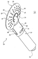
- FIG. 1 shows a sanitary hand shower 10, which comprises a handle 12 and a removable, releasably connected to the handle 12 shower head 14.
- a locking device 18 is provided in the end section 16 of the handle 12 which is adjacent to the shower head 14, from which in FIG. 1 two opposing rockers 20 can be seen.
- connection nipple 22 is provided, to which a shower hose can be attached.
- connection nipple 22 of the handle 12 is a running inside the same, here not to be recognized water-bearing channel. From this water can be done via a here not further relevant, operable by the user from the outside Umstell Rhein 24 via inner channels in the handle 12 to each one of three inner waterways 26, 28, 30 in the shower head 14 whose course in FIG. 2 can be seen.
- Each of the waterways 26, 28, 30 leads to each functionally different, serving as water outlet openings nozzles 32, 34 and 36th
- the nozzles 32, 34, 36 are provided in a known manner as a nozzle plate 38 side of a two-part housing 40 of the shower head 14.
- the nozzles 32, 34, 36 form three groups of nozzles in the illustrated embodiment.
- With the radially inner nozzles 32 can be quite hard, usually produce a massage effect water jets.
- These nozzles 32 are bypassed by a circular-shaped nozzle 34, which can be seen a surge water jet.
- the slit nozzle 34 in turn is surrounded by a relatively large number of nozzles 36 in an annular region which extends to close to the peripheral edge of the housing 40 of the shower head 14. From these nozzles 36 occurs during operation of the hand shower a variety of relatively soft, perceived as particularly pleasant effervescent jets.
- each of the connecting pieces 42, 44, 46 of the shower head 14 sits in each case a complementary receptacle in the end portion 16 of the handle 12, which is not shown here in detail.
- each of the connecting pieces 42, 44, 46 has a circumferential groove 48, in which an O-ring can be located. In the Figures 2 . 3 and 4 only each groove 48 of the connecting piece 38 is provided with a reference numeral.
- the two-part housing 40 of the shower head 14 comprises a previously mentioned nozzle plate 38 forming lower shell 50 and one of these opposite upper shell 52, which are subsequently glued together tightly or welded.
- the waterways 26, 28, 30 are formed in the shower head 14, be it already in a molding injection process or only later by milling and / or drilling.
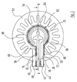
- FIG. 2 shows a view of the upper shell 52 with a view of their case in composite housing 40 inwardly facing side.
- the upper shell 52 has a slot-shaped groove 54 on a circular arc extending over an angle of about 315 °, which is arranged between the waterway 26 and the waterway 30.
- the opposite ends of this circular groove 54 are the connection piece 42, 44, 46 facing.
- a straight slot-shaped groove 56 extends in each case in the direction of the connection pieces 42, 44, 46 and parallel to its longitudinal axis (cf. FIG. 2 ).
- the arcuate groove 54 has in an angular range of about 240 ° five equally spaced portions 58, in which the groove 54 is radially widened (wider).
- a groove 54, 56, 58 corresponding groove is provided so that when assembled housing 40 of the shower head 14, a receiving space 60 forms, which in section FIG. 3 can be seen.
- This receiving space 60 serves to receive a light-emitting diode arrangement 62, which comprises a ribbon cable 64.
- the course of the ribbon cable 64 corresponds to that of the receiving space 60, ie the ribbon cable 64 has two opposing rectilinear Sections 66 and a circular arc section 68 on.
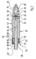
- the rectilinear portions 66 of the ribbon cable 64 form terminals 72, 74 of the light emitting diode array 62. These terminals 72, 74 are provided with a in FIG. 3 visible, housed in a recess 76 of the lower shell 50 electronics board 78 is connected. The electronics board 78 in turn is fed by a mounted in a recess 80 in the opposite upper shell 52 accumulator 82.
- the accumulator 82 can be charged via two formed as contacts terminals 84, 86, which are provided on the handle 12 associated end face of the shower head 14, with the shower head 14 removed, which will be explained in more detail below.
- Each of the terminals 84, 86 of the shower head 14 is seated opposite the housing 40 in a recess 88 or 90 provided therein.
- the accumulator 82 has two pole terminals 92, each of which has a respective spring contact 94 with one of the terminals 84, 86 is connected. This is in FIG. 3 to recognize the example of the terminal 86 of the shower head 14 connected to the pole terminal 92 of the accumulator 82.
- the light-emitting diodes 70 of the light-emitting diode arrangement 62 are energized from the accumulator 82 via the ribbon cable 64, so that they emit light.
- the LEDs 70 are aligned that they radiate their light mainly radially outward and this radiates through the radially outer edge region of the housing 40.
- the two shells 50, 52 of the housing 40 are made of a transparent material, for which preferably polycarbonates (PC) or polymethyl methacrylate (PMMA) come into consideration.
- FIG. 5 a charger, generally designated by the reference numeral 96, for charging the accumulator 82 in the shower head 14 is shown.
- the charger comprises a stand housing 98, in which the usual, known per se electronic components of a charger are housed. From the housing 98 enters a FIG. 5 only partially shown power cord. 100, with which the charger 96 can be connected to the mains.
- the charger 96 On the upper side of the housing 98, the charger 96 has a receiving region 102 for receiving the shower head 14.
- the receiving unit 102 is fork-shaped and has an inner contour that is complementary to the outer contour of a coupling region 114 of the shower head 14.
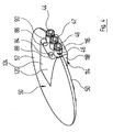
- the coupling region 114 of the shower head 14 is, as it is in FIG. 4 can be seen, provided at its in operation of the hand shower 10 the handle 12 side facing. It comprises a flat end face 116, which runs perpendicular to the longitudinal axis of the connection piece 42, 44, 46 of the shower head 14, which in turn project beyond the end face 116.
- the connections 84, 86 for connecting the accumulator 82 to the charger 96 are seated.
- the coupling region 114 of the shower head 114 also includes a lower and an upper lateral surface 118, 120, which each have a portion of the lower shell 50 and the Upper shell 52 of the housing 40 of the shower head 14 form (see. FIG. 4 ) and in each case one to the parting plane of the shells 50, 52 parallel extending portion 122 and 124, respectively. The latter is in FIG. 4 only the area 124 can be seen.
- the receiving unit 102 When inserted with its coupling region 114 in the charger 96 and in its receiving unit 102 shower head 14, the receiving unit 102 surrounds the shells 50, 52 of the housing 40 of the shower head 14. As it is in FIG. 5 is indicated, the receiving unit 102 of the charger 96 includes three blind holes 104, 106, 108, which are complementary to the connecting pieces 42, 44, 46 of the shower head 14 and record this when the shower head 14 is inserted into the charger 96.
- two spring-loaded contact pins 110, 112 are provided in the charger 96 adjacent to the blind holes 104, 106, 108 in the receiving unit 102.
- Each one of the contact pins 110, 112 of the charger 96 is connected to one of the terminals 84, 86 in the charger 96 inserted shower head 14, whereby the accumulator 82 in the shower head 14 via the terminals 84, 86 and the spring contacts 84 with a charging current is supplied.
- the light-emitting diodes 70 of the light-emitting diode arrangement 62 can be controlled during the charging process, for example via the electronic board 78 in the shower head 14 such that they generate a flashing light during the charging process, which changes into a continuous light when charging is completed.
- the hand-held shower 10 and the charger 96 are both technically, for example the charging current, as well as related to the design coordinated sanitary system for charging a hand shower with powered via a battery components.
Landscapes
- Public Health (AREA)
- Health & Medical Sciences (AREA)
- Engineering & Computer Science (AREA)
- Epidemiology (AREA)
- Hydrology & Water Resources (AREA)
- Water Supply & Treatment (AREA)
- Life Sciences & Earth Sciences (AREA)
- General Engineering & Computer Science (AREA)
- Bathtubs, Showers, And Their Attachments (AREA)
- Fittings On The Vehicle Exterior For Carrying Loads, And Devices For Holding Or Mounting Articles (AREA)
- Orthopedics, Nursing, And Contraception (AREA)
- Toilet Supplies (AREA)
- Domestic Plumbing Installations (AREA)
Description
- Die Erfindung betrifft ein sanitäres System mit einer Handbrause und einer Ladeeinheit, wobei die Handbrause umfaßt: einen an einem Brauseschlauch anschließbaren Handgriff; einen von dem Handgriff getragenen Duschkopf; mindestens ein in dem Duschkopf angeordnetes Leuchtmittel; und mindestens einen Akkumulator, durch welchen das Leuchtmittel mit Energie versorgbar ist und welcher mit von außen zugänglichen Anschlüssen zur Verbindung mit der Ladeeinheit zum Aufladen des Akkumulators verbunden ist.
- Ein derartiges sanitäres System ist in der
WO 2005/118967 A1 beschrieben. Unter Akkumulator ist grundsätzlich jede wiederaufladbare Batterie zu verstehen. Zum Aufladen des dort im Handgriff untergebrachten Akkumulators wird in derWO 2005/118967 A1 die Handbrause in eine im Verwendungsbereich der Handbrause angebrachte Ladeeinheit eingesteckt. Die Ladeeinheit bildet gleichzeitig die Halterung für die Handbrause, in welcher die Handbrause normalerweise untergebracht ist, wenn sie nicht in Gebrauch ist. Das Ladegerät ist in seinem sichtbaren Design auf das sichtbare Design der Handbrause abgestimmt, was den heutigen Ansprüchen von Benutzern an das äußere Erscheinungsbild von zusammenwirkenden Einzelkomponenten eines sanitären Systems der eingangs genannten Art entspricht, die stets als zusammengehörig erkannt werden sollen. - Der Akkumulator kann vom Benutzer nur aufgeladen werden, indem dieser die Handbrause als Ganzes in die Ladestation bringt, welche sich dazu im Naßbereich des Badezimmers befindet. Der Gedanke, daß im Naßbereich seines Badezimmers Strom, nämlich der Ladestrom zum Aufladen des Akkumulators, fließt, ist jedoch manchem Benutzer unangenehm und wird als Gefahrenquelle empfanden.
- Es besteht daher Bedarf an einem sanitären System der eingangs genannten Art, bei welchem der Akkumulator von dem Naßbereich entfernt aufgeladen werden kann. Gleichzeitig soll beim Betrachter aber ein einheitlicher äußerlicher Gesamteindruck der Einzelkomponenten erweckt werden, welcher deren Systemzusammengehörigkeit wiederspiegelt, auch wenn die Aufladung des Akkumulators erfolgt.
- Diese Aufgabe wird bei einem sanitären System der eingangs genannten Art dadurch gelöst, daß
- der Akkumulator in dem Duschkopf untergebracht ist und der Duschkopf in einem Koppelbereich die Anschlüsse zur Verbindung des Akkumulators mit der Ladeeinheit aufweist;
- der Duschkopf von dem Handgriff abnehmbar ist; und
- die Ladeeinheit einen Aufnahmebereich umfaßt, in welchen der Duschkopf mit seinem Koppelbereich zum Aufladen des Akkumulators einbringbar ist und welcher eine zur äußeren Kontur des Koppelbereichs des Duschkopfs komplementäre Innenkontur hat.
- Der Duschkopf mit dem Akkumulator kann bei dieser Ausbildung einfach vom Benutzer von dem Handgriff der Handbrause getrennt und der Ladeeinheit, die sich nicht im Naßbereich des Badezimmers befinden muß, zugeführt werden. Diese wiederum weist einen komplementär an die äußere Kontur des Duschkopfs angepaßten Aufnahmebereich auf, von welchem der in die Ladeeinheit eingebrachte Duschkopf formschlüssig aufgenommen werden kann. Auf Grund dieser Formschlüssigkeit bei in die Ladeeinheit eingesetztem Duschkopf wird beim Betrachter ein äußerlicher Gesamteindruck erweckt, der die Systemzusammengehörigkeit der Komponenten ausdrückt.
- Vorteilhafte Weiterbildungen der Erfindung sind in den abhängigen Ansprüchen angegeben.
- Ein Ausführungsbeispiel der Erfindung wird nachfolgend anhand der Zeichnung näher erläutert. In dieser zeigen:
- Figur 1
- eine isometrische Darstellung einer sanitären Handbrause eines sanitären Systems, welche einen abnehmbaren zweiteiligen Duschkopf umfaßt;
- Figur 2
- eine Ansicht von unten auf den in
Figur 1 oberen Teil des zweiteiligen Duschkopfs; - Figur 3
- einen Schnitt durch den Duschkopf von
Figur 1 entlang der Schnittlinie III-III inFigur 2 ; - Figur 4
- eine isometrische Darstellung des Duschkopfs der Handbrause von
Figur 1 ; und - Figur 5
- ein Ladegerät des sanitären Systems.
-
Figur 1 zeigt eine sanitäre Handbrause 10, welche einen Handgriff 12 sowie einen abnehmbaren, mit dem Handgriff 12 lösbar verbundenen Duschkopf 14 umfaßt. Zur lösbaren Verbindung des Duschkopfs 14 mit dem Handgriff 12 ist in dem dem Duschkopf 14 benachbarten Endabschnitt 16 des Handgriffs 12 eine hier nicht weiter interessierende Verriegelungseinrichtung 18 vorgesehen, von der inFigur 1 zwei sich gegenüberliegende Betätigungswippen 20 zu erkennen sind. - An dem dem Duschkopf 14 gegenüberliegenden Ende des Handgriffs 12 ist ein Anschlußnippel 22 vorgesehen, an welchem ein Brauseschlauch befestigt werden kann. Von dem Anschlußnippel 22 des Handgriffs 12 geht ein im Inneren desselben verlaufender, hier nicht zu erkennender wasserführender Kanal ab. Von diesem kann Wasser über eine hier ebenfalls nicht weiter relevante, vom Benutzer von außen betätigbare Umstelleinrichtung 24 über innere Kanäle im Handgriff 12 zu jeweils einem von drei inneren Wasserwegen 26, 28, 30 im Duschkopf 14 geführt werden, deren verlauf in
Figur 2 zu erkennen ist. Jeder der Wasserwege 26, 28, 30 führt zu jeweils funktionell unterschiedlichen, als Wasseraustrittsöffnungen dienenden Düsen 32, 34 bzw. 36. - Die Düsen 32, 34, 36 sind in einer in bekannter Weise als Düsenplatte 38 ausgebildeten Seite eines zweiteiligen Gehäuses 40 des Duschkopfs 14 vorgesehen. Die Düsen 32, 34, 36 bilden beim dargestellten Ausführungsbeispiel drei Gruppen von Düsen. Mit den radial innenliegenden Düsen 32 lassen sich recht harte, in der Regel eine Massagewirkung erzielende Wasserstrahlen erzeugen. Diese Düsen 32 werden von einer kreisbogenförmigen Düse 34 umgehen, welcher sich ein schwallartiger Wasserstrahl entnehmen läßt. Die Schlitzdüse 34 ihrerseits ist in einem Ringbereich, der bis nahe an den umlaufenden Rand des Gehäuses 40 des Duschkopfs 14 heranreicht, von verhältnismäßig vielen Düsen 36 umgeben. Aus diesen Düsen 36 tritt im Betrieb der Handbrause eine Vielzahl von relativ weichen, als besonders angenehm empfundenen Brausestrahlen aus.
- Zur Verbindung der inneren Wasserwege 26, 28, 30 im Duschkopf 14 mit den entsprechenden, hier nicht gezeigten Kanälen im Handgriff 12 münden die Wasserwege 26, 28, 30 jeweils in radial außenliegenden Verbindungsstutzen 42, 44, 46, welche über den Umfangsrand des Gehäuses 40 überstehen, wie dies in den
Figuren 2 ,3 und4 zu erkennen ist. Mit jedem dieser Verbindungsstutzen 42, 44, 46 sitzt der Duschkopf 14 in jeweils einer dazu komplementären Aufnahme im Endabschnitt 16 des Handgriffes 12, welche hier im einzelnen nicht gezeigt ist. Zur Abdichtung gegenüber dieser Aufnahme weist jeder der Verbindungsstutzen 42, 44, 46 eine umlaufende Nut 48 auf, in welche ein O-Ring einsitzen kann. In denFiguren 2 ,3 und4 ist nur jeweils die Nut 48 des Verbindungsstutzens 38 mit einem Bezugszeichen versehen. - Das zweiteilig ausgebildete Gehäuse 40 des Duschkopfs 14 umfaßt eine die bereits erwähnte Düsenplatte 38 bildende Unterschale 50 sowie eine dieser gegenüberliegende Oberschale 52, welche nachträglich miteinander dicht verklebt oder verschweißt sind. In beiden Schalen 50, 52 sind die Wasserwege 26, 28, 30 im Duschkopf 14 ausgeformt, sei dies bereits bei einem formgebenden Spritzprozeß oder erst nachträglich durch Fräsen und/oder Bohren.
-
Figur 2 zeigt eine Ansicht der Oberschale 52 mit Blick auf deren bei zusammengesetztem Gehäuse 40 nach innen weisende Seite. Auf dieser Seite weist die Oberschale 52 auf einem sich über einen Winkel von etwa 315° erstreckenden Kreisbogen, der zwischen dem Wasserweg 26 und dem Wasserweg 30 angeordnet ist, eine schlitzförmige Nut 54 auf. Die sich gegenüberliegenden Enden dieser kreisbogenförmigen Nut 54 sind den Verbindungsstutzen 42, 44, 46 zugewandt. Von jedem dieser Enden der Nut 54 ausgehend verläuft jeweils eine geradlinige schlitzförmige Nut 56 in Richtung auf die Verbindungsstutzen 42, 44, 46 und parallel zu deren Längsachse (vgl.Figur 2 ). Die kreisbogenförmige Nut 54 weist in einem Winkelbereich von etwa 240° fünf gleichmäßig voneinander beabstandete Abschnitte 58 auf, in welchen die Nut 54 radial erweitert (breiter) ist. - Auf der bei zusammengesetztem Gehäuse 40 nach innen weisenden Seite der die Düsenplatte 38 bildenden Schale 50 ist eine der Nut 54, 56, 58 entsprechende Nut vorgesehen, so daß sich bei zusammengesetztem Gehäuse 40 des Duschkopfs 14 ein Aufnahmeraum 60 bildet, welcher im Schnitt in
Figur 3 zu erkennen ist. Dieser Aufnahmeraum 60 dient der Aufnahme einer Leuchtdioden-Anordnung 62, welche ein Flachbandkabel 64 umfaßt. Der Verlauf des Flachbandkabels 64 entspricht demjenigen des Aufnahmeraumes 60, d.h. das Flachbandkabel 64 weist zwei sich gegenüberliegende geradlinige Abschnitte 66 sowie einen kreisbogenförmigen Abschnitt 68 auf. Auf dem kreisbogenförmigen Abschnitt 68 des Flachbandkabels 64 sind fünf Leuchtdioden 70 derart angebracht, daß jeweils eine Leuchtdiode 70 in einem erweiterten Abschnitt 58 des Aufnahmeraums 60 sitzt, wenn das Flachbandkabel 64 mit den Leuchtdioden 70 in den Aufnahmeraum 60 eingebracht ist. - Die geradlinigen Abschnitte 66 des Flachbandkabels 64 bilden Anschlußklemmen 72, 74 der Leuchtdioden-Anordnung 62. Diese Anschlußklemmen 72, 74 sind mit einer in
Figur 3 sichtbaren, in einer Aussparung 76 der Unterschale 50 untergebrachten Elektronikplatine 78 verbunden. Die Elektronikplatine 78 ihrerseits wird von einem in einer Ausnehmung 80 in der gegenüberliegenden Oberschale 52 angebrachten Akkumulator 82 gespeist. Der Akkumulator 82 kann über zwei als Kontakte ausgebildete Anschlüsse 84, 86, welche an der dem Handgriff 12 zugeordneten Stirnseite des Duschkopfs 14 vorgesehen sind, bei abgenommenem Duschkopf 14 aufgeladen werden, was nachstehend noch näher erläutert wird. - Jeder der Anschlüsse 84, 86 des Duschkopfs 14 sitzt dem Gehäuse 40 gegenüber ortsfest in einer darin vorgesehenen Ausnehmung 88 bzw. 90. Der Akkumulator 82 hat zwei Pol-Anschlüsse 92, von denen jeder über jeweils einen Federkontakt 94 mit jeweils einem der Anschlüsse 84, 86 in Verbindung steht. Dies ist in
Figur 3 am Beispiel des mit dem Anschluß 86 des Duschkopfs 14 verbundenen Pol-Anschlusses 92 des Akkumulators 82 zu erkennen. - Im Betrieb der Handbrause 10 werden die Leuchtdioden 70 der Leuchtdioden-Anordnung 62 aus dem Akkumulator 82 über das Flachbandkabel 64 bestromt, so daß sie Licht emittieren. Die Leuchtdioden 70 sind so ausgerichtet, daß sie ihr Licht hauptsächlich radial nach außen abstrahlen und dieses den radial außenliegenden Randbereich des Gehäuses 40 durchstrahlt. Dazu sind die beiden Schalen 50, 52 des Gehäuses 40 aus einem transparenten Material gefertigt, wofür vorzugsweise Polycarbonate (PC) oder Polymethylmethacrylat (PMMA) in Betracht kommen.
- In
Figur 5 ist ein insgesamt mit dem Bezugszeichen 96 bezeichnetes Ladegerät zur Aufladung des Akkumulators 82 im Duschkopf 14 gezeigt. Das Ladegerät umfaßt ein Standgehäuse 98, in welchem die üblichen, an und für sich bekannten elektronischen Komponenten eines Ladegeräts untergebracht sind. Aus dem Gehäuse 98 tritt ein inFigur 5 nur teilweise gezeigtes Netzkabel. 100 aus, mit dem das Ladegerät 96 an das Stromnetz angeschlossen werden kann. - Auf der Oberseite des Gehäuses 98 weist das Ladegerät 96 einen Aufnahmebereich 102 zur Aufnahme des Duschkopfs 14 auf. Die Aufnahmeeinheit 102 ist gabelförmig ausgebildet und weist eine innere Kontur auf, die zu der Außenkontur eines Koppelbereichs 114 des Duschkopfs 14 komplementär ist. Der Koppelbereich 114 des Duschkopfs 14 ist, wie es in
Figur 4 zu sehen ist, an dessen im Betrieb der Handbrause 10 dem Handgriff 12 zugewandten Seite vorgesehen. Er umfaßt eine ebene Stirnfläche 116, die senkrecht zur Längsachse der Verbindungsstutzen 42, 44, 46 des Duschkopfs 14 verläuft, welche ihrerseits über die Stirnfläche 116 überstehen. In der Stirnfläche 116 des Koppelbereichs 114 auf Höhe der Oberschale 52 des Duschkopfs 14 sitzen die Anschlüsse 84, 86 zur Verbindung des Akkumulators 82 mit dem Ladegerät 96. - Der Koppelbereich 114 des Duschkopfs 114 umfaßt außerdem eine untere und eine obere Mantelfläche 118, 120, welche jeweils einen Abschnitt der Unterschale 50 bzw. der Oberschale 52 des Gehäuses 40 des Duschkopfs 14 bilden (vgl.
Figur 4 ) und jeweils einen zur Trennebene der Schalen 50, 52 parallel verlaufenden Bereich 122 bzw. 124 aufweisen. Von Letzteren ist inFigur 4 lediglich der Bereich 124 zu erkennen. - Bei mit seinem Koppelbereich 114 in das Ladegerät 96 bzw. in dessen Aufnahmeeinheit 102 eingesetztem Duschkopf 14 umgreift die Aufnahmeeinheit 102 die Schalen 50, 52 des Gehäuses 40 des Duschkopfs 14. Wie es in
Figur 5 angedeutet ist, umfaßt die Aufnahmeeinheit 102 des Ladegeräts 96 drei Sackbohrungen 104, 106, 108, welche zu den Verbindungsstutzen 42, 44, 46 des Duschkopfs 14 komplementär ausgebildet sind und diese aufnehmen, wenn der Duschkopf 14 in das Ladegerät 96 eingesetzt ist. - Entsprechend den Positionen der Anschlüsse 84, 86 des Duschkopfs 14 sind bei dem Ladegerät 96 benachbart zu den Sackbohrungen 104, 106, 108 in der Aufnahmeeinheit 102 zwei federgelagerte Kontaktstifte 110, 112 vorgesehen. Jeweils einer der Kontaktstifte 110, 112 des Ladegeräts 96 steht bei in das Ladegerät 96 eingesetztem Duschkopf 14 mit einem von dessen Anschlüssen 84, 86 in Verbindung, wodurch der Akkumulator 82 im Duschkopf 14 über die Anschlüsse 84, 86 und die Federkontakte 84 mit einem Ladestrom versorgt wird.
- Die Leuchtdioden 70 der Leuchtdioden-Anordnung 62 können beim Ladevorgang beispielsweise über die Elektronikplatine 78 im Duschkopf 14 derart angesteuert werden, daß sie während des Ladevorgangs ein Blinklicht erzeugen, welches bei abgeschlossenem Ladevorgang in ein Dauerlicht übergeht.
- Insgesamt bilden die Handbrause 10 und das Ladegerät 96 ein sowohl in technischer Hinsicht, was beispielsweise den Ladestrom betrifft, als auch bezogen auf das Design aufeinander abgestimmtes sanitäres System zur Aufladung einer Handbrause mit über einen Akkumulator gespeisten Komponenten.
Claims (6)
- Sanitäres System mit einer Handbrause (10) und einer Ladeeinheit (96), wobei die Handbrause (10) umfaßt : einen an einen Brauseschlauch anschließbaren Handgriff (12) ; einen von dem Handgriff (12) getragenen Duschkopf (14) ; mindestens ein in dem Duschkopf (14) angeordnetes Leuchtmittel (62); und mindestens einen Akkumulator (82), durch welchen das Leuchtmittel (62) mit Energie versorgbar ist und welcher mit von außen zugänglichen Anschlüssen (84, 86) zur Verbindung mit der Ladeeinheit (96) zum Aufladen des Akkumulators (82) verbunden ist;
dadurch gekennzeichnet, daßder Akkumulator (82) in dem Duschkopf (14) untergebracht ist und der Duschkopf (14) in einem Koppelbereich (114) die Anschlüsse (84, 86) zur Verbindung des Akkumulators (82) mit der Ladeeinheit (96) aufweist;der Duschkopf (14) von dem Handgriff (12) abnehmbar ist;
unddie Ladeeinheit (96) einen Aufnahmebereich (102) umfaßt, in welchen der Duschkopf (14) mit seinem Koppelbereich (114) zum Aufladen des Akkumulators (82) einbringbar ist und welcher eine zur äußeren Kontur des Koppelbereichs (114) des Duschkopfs (14) komplementäre Innenkontur hat. - Sanitäres System nach Anspruch 1, dadurch gekennzeichnet, daß der Duschkopf (14) ein zweitteiliges Gehäuse (40) aufweist und der Akkumulator (82) in einer Ausnehmung (80) in einem der Gehäuseteile (50, 52) sitzt.
- Sanitäres System nach Anspruch 1 oder 2, dadurch
gekennzeichnet, daß der Akkumulator (82) über Federkontakte (94) mit den Anschlüssen (84, 86) des Duschkopfs (14) verbunden ist. - Sanitäres System nach einem der Ansprüche 1 bis 3,
dadurch gekennzeichnet, daß das Leuchtmittel (62) wenigstens eine Leuchtdiode (70) umfaßt. - Sanitäres System nach einem der Ansprüche 1 bis 4,
dadurch gekennzeichnet, daß das Leuchtmittel (62) ein Flachbandkabel (64) umfaßt, über welches die Stromversorgung des Leuchtmittels (62) durch den Akkumulator (82) erfolgt. - Sanitäres System nach Anspruch 5, dadurch gekennzeichnet, daß das Flachbandkabel (64) Leuchtdioden (70) trägt.
Applications Claiming Priority (2)
| Application Number | Priority Date | Filing Date | Title |
|---|---|---|---|
| DE102006021697A DE102006021697B3 (de) | 2006-05-10 | 2006-05-10 | Sanitäres System mit einer Handbrause und einer Ladeeinheit |
| PCT/EP2007/003794 WO2007128447A1 (de) | 2006-05-10 | 2007-04-28 | Sanitäres system mit einer handbrause und einer ladeeinheit |
Publications (2)
| Publication Number | Publication Date |
|---|---|
| EP2016231A1 EP2016231A1 (de) | 2009-01-21 |
| EP2016231B1 true EP2016231B1 (de) | 2010-06-09 |
Family
ID=38294232
Family Applications (1)
| Application Number | Title | Priority Date | Filing Date |
|---|---|---|---|
| EP07724721A Not-in-force EP2016231B1 (de) | 2006-05-10 | 2007-04-28 | Sanitäres system mit einer handbrause und einer ladeeinheit |
Country Status (6)
| Country | Link |
|---|---|
| US (1) | US20090236444A1 (de) |
| EP (1) | EP2016231B1 (de) |
| CN (1) | CN101438010B (de) |
| AT (1) | ATE470762T1 (de) |
| DE (2) | DE102006021697B3 (de) |
| WO (1) | WO2007128447A1 (de) |
Families Citing this family (6)
| Publication number | Priority date | Publication date | Assignee | Title |
|---|---|---|---|---|
| EP2172273B1 (de) * | 2008-10-04 | 2012-11-21 | Kwc Ag | Brause mit trennbarem Halteteil und Brausekopf |
| DK2172274T3 (da) * | 2008-10-04 | 2011-04-26 | Kwc Ag | Indstilleligt bruserhoved |
| JP5141998B1 (ja) * | 2012-03-16 | 2013-02-13 | Toto株式会社 | ハンドシャワーヘッド |
| US8911100B2 (en) * | 2013-03-15 | 2014-12-16 | Agreat Shower & Sanitary (Xiamen) Co., Ltd. | Self-generating lighting shower head |
| US9931651B2 (en) * | 2014-08-28 | 2018-04-03 | Nebia Inc. | Immersive showerhead |
| US11602032B2 (en) | 2019-12-20 | 2023-03-07 | Kohler Co. | Systems and methods for lighted showering |
Family Cites Families (30)
| Publication number | Priority date | Publication date | Assignee | Title |
|---|---|---|---|---|
| US3696973A (en) * | 1969-12-09 | 1972-10-10 | Cottell Eric Charles | Hand-held air compressor and liquid spray device |
| US4564889A (en) * | 1982-11-10 | 1986-01-14 | Bolson Frank J | Hydro-light |
| US4616298A (en) * | 1985-12-26 | 1986-10-07 | Bolson Frank J | Water-powered light |
| CN2128109Y (zh) * | 1992-07-03 | 1993-03-17 | 李勇军 | 一种新型淋浴头 |
| CN2188916Y (zh) * | 1994-01-18 | 1995-02-08 | 李晓军 | 震动按摩磁化淋浴冲洗器 |
| CN2269169Y (zh) * | 1996-09-16 | 1997-12-03 | 阳剑 | 热水器淋浴喷头 |
| IL119431A (en) * | 1996-10-15 | 2000-10-31 | Joel Kehat | Colored light shower head |
| US5795053A (en) * | 1996-12-09 | 1998-08-18 | Pierce; Adam Benson | Illuminated fire hose rescue nozzle |
| DE19654359C1 (de) * | 1996-12-24 | 1998-08-20 | Gunter Veigel | Wasserauslaufarmatur |
| US5873647A (en) * | 1997-03-27 | 1999-02-23 | Kurtz; Rodney | Nozzle mounted lamp |
| KR100308732B1 (ko) * | 1998-05-13 | 2002-01-15 | 이정규 | 조명수단을가지는소방노즐 |
| US6257750B1 (en) * | 1999-07-09 | 2001-07-10 | Richard T. Strasser | Illuminating fire hose |
| US6637676B2 (en) * | 2001-04-27 | 2003-10-28 | Interbath, Inc. | Illuminated showerhead |
| US6439472B1 (en) * | 2001-05-17 | 2002-08-27 | Bi Guang Tsai | Sprayer device having a light or warning device |
| DE10146815B4 (de) * | 2001-09-18 | 2005-05-04 | Ing. Erich Pfeiffer Gmbh | Spender für Medien |
| US7040546B2 (en) * | 2002-03-20 | 2006-05-09 | Laser Touch And Technologies, Llc | Single beam spray gun positioning system |
| US6857582B1 (en) * | 2002-09-03 | 2005-02-22 | Calvin S. Wang | Vehicle windshield spraying and lighting assembly |
| US7469844B2 (en) * | 2002-11-08 | 2008-12-30 | S.C. Johnson & Son, Inc. | Diffusion device and method of diffusing |
| CN2612462Y (zh) * | 2003-03-10 | 2004-04-21 | 杨杰 | 充电式多功能沐浴喷头 |
| DE10312866A1 (de) * | 2003-03-19 | 2004-09-30 | Hansgrohe Ag | Dusche |
| CA2526362C (en) * | 2003-05-20 | 2012-10-09 | James F. Collins | Ophthalmic drug delivery system |
| US6983898B2 (en) * | 2003-05-21 | 2006-01-10 | Frank Clark | Showerhead with optical lens feature |
| US7387401B2 (en) * | 2004-01-21 | 2008-06-17 | Frank Clark | Showerhead with turbine driven light source |
| US20050184788A1 (en) * | 2004-02-25 | 2005-08-25 | Johansson Brian D. | Logic level voltage translator |
| US7468127B2 (en) * | 2004-03-16 | 2008-12-23 | Chao Fou Hsu | Hand held shower head with filter replacing pre-alarm assembly |
| DE102004028608A1 (de) * | 2004-06-04 | 2005-12-22 | Hansgrohe Ag | Handbrause |
| DE102004051257A1 (de) * | 2004-10-21 | 2006-05-24 | Muhl, Rüdiger | Armatur mit Schnellspannverschluß |
| ES2314505T3 (es) * | 2005-03-11 | 2009-03-16 | Kwc Ag | Grifo sanitario con un tubo de descarga conductor de la luz. |
| US20070022528A1 (en) * | 2005-08-01 | 2007-02-01 | Gilbert Christopher J | Combination handheld shower and stationary showerhead |
| TWM331948U (en) * | 2007-08-07 | 2008-05-11 | kun-song Lv | Rotation and light-emitting structure of shower nozzle |
-
2006
- 2006-05-10 DE DE102006021697A patent/DE102006021697B3/de not_active Expired - Fee Related
-
2007
- 2007-04-28 CN CN2007800165500A patent/CN101438010B/zh not_active Expired - Fee Related
- 2007-04-28 WO PCT/EP2007/003794 patent/WO2007128447A1/de not_active Ceased
- 2007-04-28 AT AT07724721T patent/ATE470762T1/de active
- 2007-04-28 DE DE502007004078T patent/DE502007004078D1/de active Active
- 2007-04-28 US US12/299,697 patent/US20090236444A1/en not_active Abandoned
- 2007-04-28 EP EP07724721A patent/EP2016231B1/de not_active Not-in-force
Also Published As
| Publication number | Publication date |
|---|---|
| DE102006021697B3 (de) | 2007-10-11 |
| US20090236444A1 (en) | 2009-09-24 |
| ATE470762T1 (de) | 2010-06-15 |
| CN101438010B (zh) | 2011-02-02 |
| DE502007004078D1 (de) | 2010-07-22 |
| CN101438010A (zh) | 2009-05-20 |
| WO2007128447A1 (de) | 2007-11-15 |
| EP2016231A1 (de) | 2009-01-21 |
Similar Documents
| Publication | Publication Date | Title |
|---|---|---|
| EP2016231B1 (de) | Sanitäres system mit einer handbrause und einer ladeeinheit | |
| EP2684610A1 (de) | Brause | |
| EP0173371A1 (de) | Hörgerät | |
| DE202016100723U1 (de) | Fernbedienungseinrichtung | |
| DE3807287A1 (de) | Elektrisch betriebener handhaartrockner | |
| DE20105186U1 (de) | Einstellbare Vorderlampe für ein Fahrrad | |
| EP2940220A1 (de) | Wannenfüllbatterie mit drei mischwasserabgängen | |
| EP1751356B1 (de) | Handbrause | |
| EP2016232B1 (de) | Sanitäre handbrause | |
| DE2937206A1 (de) | Messinstrumentengehaeuse | |
| DE102006021701B4 (de) | Sanitäre Handbrause | |
| EP2148015B1 (de) | Sanitärarmatur mit einem lichtleitenden Ausflussrohr | |
| DE2712759A1 (de) | Schluesselkappe | |
| DE3507212C2 (de) | ||
| EP0955031A2 (de) | Bademassagegerät | |
| DE102006020766A1 (de) | Sanitäre Handbrause | |
| DE29519433U1 (de) | Lichtakupunktur-Behandlungsgerät | |
| EP2015872A1 (de) | Sanitäre handbrause | |
| DE102006020769B4 (de) | Sanitäre Handbrause | |
| DE102008040933A1 (de) | Gehäuse für ein Haushaltsgerät, insbesondere einen Stabmixer, und Haushaltsgerät | |
| DE102019200012A1 (de) | Brausekopf mit Strahlscheibenhaltevorrichtung | |
| DE19624310B4 (de) | Mit einem abnehmbaren Block versehene elektrische Steuerungs- oder Signalisierungsvorrichtung | |
| DE20212768U1 (de) | Stuhlführung für einen hin- und herverfahrbaren Stuhl | |
| DE202015101721U1 (de) | Vorrichtung zum Kalibrieren eines Bohreinsatzes für ein Bohrmaschinenfutter | |
| DE2908082A1 (de) | Montageflansch zur befestigung an waschtischen, spueltischen o.dgl. |
Legal Events
| Date | Code | Title | Description |
|---|---|---|---|
| PUAI | Public reference made under article 153(3) epc to a published international application that has entered the european phase |
Free format text: ORIGINAL CODE: 0009012 |
|
| 17P | Request for examination filed |
Effective date: 20081107 |
|
| AK | Designated contracting states |
Kind code of ref document: A1 Designated state(s): AT BE BG CH CY CZ DE DK EE ES FI FR GB GR HU IE IS IT LI LT LU LV MC MT NL PL PT RO SE SI SK TR |
|
| AX | Request for extension of the european patent |
Extension state: AL BA HR MK RS |
|
| GRAP | Despatch of communication of intention to grant a patent |
Free format text: ORIGINAL CODE: EPIDOSNIGR1 |
|
| DAX | Request for extension of the european patent (deleted) | ||
| GRAS | Grant fee paid |
Free format text: ORIGINAL CODE: EPIDOSNIGR3 |
|
| GRAA | (expected) grant |
Free format text: ORIGINAL CODE: 0009210 |
|
| AK | Designated contracting states |
Kind code of ref document: B1 Designated state(s): AT BE BG CH CY CZ DE DK EE ES FI FR GB GR HU IE IS IT LI LT LU LV MC MT NL PL PT RO SE SI SK TR |
|
| REG | Reference to a national code |
Ref country code: CH Ref legal event code: EP |
|
| REG | Reference to a national code |
Ref country code: IE Ref legal event code: FG4D Free format text: LANGUAGE OF EP DOCUMENT: GERMAN |
|
| REF | Corresponds to: |
Ref document number: 502007004078 Country of ref document: DE Date of ref document: 20100722 Kind code of ref document: P |
|
| REG | Reference to a national code |
Ref country code: CH Ref legal event code: NV Representative=s name: FREI PATENTANWALTSBUERO AG |
|
| REG | Reference to a national code |
Ref country code: NL Ref legal event code: VDEP Effective date: 20100609 |
|
| PG25 | Lapsed in a contracting state [announced via postgrant information from national office to epo] |
Ref country code: LT Free format text: LAPSE BECAUSE OF FAILURE TO SUBMIT A TRANSLATION OF THE DESCRIPTION OR TO PAY THE FEE WITHIN THE PRESCRIBED TIME-LIMIT Effective date: 20100609 Ref country code: SE Free format text: LAPSE BECAUSE OF FAILURE TO SUBMIT A TRANSLATION OF THE DESCRIPTION OR TO PAY THE FEE WITHIN THE PRESCRIBED TIME-LIMIT Effective date: 20100609 |
|
| LTIE | Lt: invalidation of european patent or patent extension |
Effective date: 20100609 |
|
| PG25 | Lapsed in a contracting state [announced via postgrant information from national office to epo] |
Ref country code: FI Free format text: LAPSE BECAUSE OF FAILURE TO SUBMIT A TRANSLATION OF THE DESCRIPTION OR TO PAY THE FEE WITHIN THE PRESCRIBED TIME-LIMIT Effective date: 20100609 Ref country code: SI Free format text: LAPSE BECAUSE OF FAILURE TO SUBMIT A TRANSLATION OF THE DESCRIPTION OR TO PAY THE FEE WITHIN THE PRESCRIBED TIME-LIMIT Effective date: 20100609 Ref country code: LV Free format text: LAPSE BECAUSE OF FAILURE TO SUBMIT A TRANSLATION OF THE DESCRIPTION OR TO PAY THE FEE WITHIN THE PRESCRIBED TIME-LIMIT Effective date: 20100609 |
|
| PG25 | Lapsed in a contracting state [announced via postgrant information from national office to epo] |
Ref country code: PL Free format text: LAPSE BECAUSE OF FAILURE TO SUBMIT A TRANSLATION OF THE DESCRIPTION OR TO PAY THE FEE WITHIN THE PRESCRIBED TIME-LIMIT Effective date: 20100609 Ref country code: CY Free format text: LAPSE BECAUSE OF FAILURE TO SUBMIT A TRANSLATION OF THE DESCRIPTION OR TO PAY THE FEE WITHIN THE PRESCRIBED TIME-LIMIT Effective date: 20100609 |
|
| REG | Reference to a national code |
Ref country code: IE Ref legal event code: FD4D |
|
| PG25 | Lapsed in a contracting state [announced via postgrant information from national office to epo] |
Ref country code: NL Free format text: LAPSE BECAUSE OF FAILURE TO SUBMIT A TRANSLATION OF THE DESCRIPTION OR TO PAY THE FEE WITHIN THE PRESCRIBED TIME-LIMIT Effective date: 20100609 Ref country code: EE Free format text: LAPSE BECAUSE OF FAILURE TO SUBMIT A TRANSLATION OF THE DESCRIPTION OR TO PAY THE FEE WITHIN THE PRESCRIBED TIME-LIMIT Effective date: 20100609 Ref country code: IE Free format text: LAPSE BECAUSE OF FAILURE TO SUBMIT A TRANSLATION OF THE DESCRIPTION OR TO PAY THE FEE WITHIN THE PRESCRIBED TIME-LIMIT Effective date: 20100609 |
|
| PG25 | Lapsed in a contracting state [announced via postgrant information from national office to epo] |
Ref country code: SK Free format text: LAPSE BECAUSE OF FAILURE TO SUBMIT A TRANSLATION OF THE DESCRIPTION OR TO PAY THE FEE WITHIN THE PRESCRIBED TIME-LIMIT Effective date: 20100609 Ref country code: RO Free format text: LAPSE BECAUSE OF FAILURE TO SUBMIT A TRANSLATION OF THE DESCRIPTION OR TO PAY THE FEE WITHIN THE PRESCRIBED TIME-LIMIT Effective date: 20100609 Ref country code: PT Free format text: LAPSE BECAUSE OF FAILURE TO SUBMIT A TRANSLATION OF THE DESCRIPTION OR TO PAY THE FEE WITHIN THE PRESCRIBED TIME-LIMIT Effective date: 20101011 Ref country code: IS Free format text: LAPSE BECAUSE OF FAILURE TO SUBMIT A TRANSLATION OF THE DESCRIPTION OR TO PAY THE FEE WITHIN THE PRESCRIBED TIME-LIMIT Effective date: 20101009 Ref country code: CZ Free format text: LAPSE BECAUSE OF FAILURE TO SUBMIT A TRANSLATION OF THE DESCRIPTION OR TO PAY THE FEE WITHIN THE PRESCRIBED TIME-LIMIT Effective date: 20100609 |
|
| PG25 | Lapsed in a contracting state [announced via postgrant information from national office to epo] |
Ref country code: IT Free format text: LAPSE BECAUSE OF FAILURE TO SUBMIT A TRANSLATION OF THE DESCRIPTION OR TO PAY THE FEE WITHIN THE PRESCRIBED TIME-LIMIT Effective date: 20100609 |
|
| PLBE | No opposition filed within time limit |
Free format text: ORIGINAL CODE: 0009261 |
|
| STAA | Information on the status of an ep patent application or granted ep patent |
Free format text: STATUS: NO OPPOSITION FILED WITHIN TIME LIMIT |
|
| PG25 | Lapsed in a contracting state [announced via postgrant information from national office to epo] |
Ref country code: DK Free format text: LAPSE BECAUSE OF FAILURE TO SUBMIT A TRANSLATION OF THE DESCRIPTION OR TO PAY THE FEE WITHIN THE PRESCRIBED TIME-LIMIT Effective date: 20100609 |
|
| PG25 | Lapsed in a contracting state [announced via postgrant information from national office to epo] |
Ref country code: GR Free format text: LAPSE BECAUSE OF FAILURE TO SUBMIT A TRANSLATION OF THE DESCRIPTION OR TO PAY THE FEE WITHIN THE PRESCRIBED TIME-LIMIT Effective date: 20100910 |
|
| REG | Reference to a national code |
Ref country code: DE Ref legal event code: R097 Ref document number: 502007004078 Country of ref document: DE Effective date: 20110309 |
|
| BERE | Be: lapsed |
Owner name: HANSA METALLWERKE A.G. Effective date: 20110430 |
|
| PG25 | Lapsed in a contracting state [announced via postgrant information from national office to epo] |
Ref country code: MC Free format text: LAPSE BECAUSE OF NON-PAYMENT OF DUE FEES Effective date: 20110430 |
|
| REG | Reference to a national code |
Ref country code: CH Ref legal event code: PL |
|
| GBPC | Gb: european patent ceased through non-payment of renewal fee |
Effective date: 20110428 |
|
| PG25 | Lapsed in a contracting state [announced via postgrant information from national office to epo] |
Ref country code: MT Free format text: LAPSE BECAUSE OF FAILURE TO SUBMIT A TRANSLATION OF THE DESCRIPTION OR TO PAY THE FEE WITHIN THE PRESCRIBED TIME-LIMIT Effective date: 20100609 |
|
| REG | Reference to a national code |
Ref country code: FR Ref legal event code: ST Effective date: 20111230 |
|
| PG25 | Lapsed in a contracting state [announced via postgrant information from national office to epo] |
Ref country code: FR Free format text: LAPSE BECAUSE OF NON-PAYMENT OF DUE FEES Effective date: 20110502 Ref country code: CH Free format text: LAPSE BECAUSE OF NON-PAYMENT OF DUE FEES Effective date: 20110430 Ref country code: LI Free format text: LAPSE BECAUSE OF NON-PAYMENT OF DUE FEES Effective date: 20110430 Ref country code: DE Free format text: LAPSE BECAUSE OF NON-PAYMENT OF DUE FEES Effective date: 20111101 Ref country code: BE Free format text: LAPSE BECAUSE OF NON-PAYMENT OF DUE FEES Effective date: 20110430 |
|
| REG | Reference to a national code |
Ref country code: DE Ref legal event code: R119 Ref document number: 502007004078 Country of ref document: DE Effective date: 20111101 |
|
| PG25 | Lapsed in a contracting state [announced via postgrant information from national office to epo] |
Ref country code: GB Free format text: LAPSE BECAUSE OF NON-PAYMENT OF DUE FEES Effective date: 20110428 |
|
| PG25 | Lapsed in a contracting state [announced via postgrant information from national office to epo] |
Ref country code: LU Free format text: LAPSE BECAUSE OF NON-PAYMENT OF DUE FEES Effective date: 20110428 |
|
| REG | Reference to a national code |
Ref country code: AT Ref legal event code: MM01 Ref document number: 470762 Country of ref document: AT Kind code of ref document: T Effective date: 20120428 |
|
| PG25 | Lapsed in a contracting state [announced via postgrant information from national office to epo] |
Ref country code: AT Free format text: LAPSE BECAUSE OF NON-PAYMENT OF DUE FEES Effective date: 20120428 |
|
| PG25 | Lapsed in a contracting state [announced via postgrant information from national office to epo] |
Ref country code: BG Free format text: LAPSE BECAUSE OF FAILURE TO SUBMIT A TRANSLATION OF THE DESCRIPTION OR TO PAY THE FEE WITHIN THE PRESCRIBED TIME-LIMIT Effective date: 20100909 Ref country code: TR Free format text: LAPSE BECAUSE OF FAILURE TO SUBMIT A TRANSLATION OF THE DESCRIPTION OR TO PAY THE FEE WITHIN THE PRESCRIBED TIME-LIMIT Effective date: 20100609 |
|
| PG25 | Lapsed in a contracting state [announced via postgrant information from national office to epo] |
Ref country code: HU Free format text: LAPSE BECAUSE OF FAILURE TO SUBMIT A TRANSLATION OF THE DESCRIPTION OR TO PAY THE FEE WITHIN THE PRESCRIBED TIME-LIMIT Effective date: 20100609 Ref country code: ES Free format text: LAPSE BECAUSE OF FAILURE TO SUBMIT A TRANSLATION OF THE DESCRIPTION OR TO PAY THE FEE WITHIN THE PRESCRIBED TIME-LIMIT Effective date: 20100920 |