EP2014239B1 - Structures tressées multicouche pour l'occlusion de défauts vasculaires - Google Patents
Structures tressées multicouche pour l'occlusion de défauts vasculaires Download PDFInfo
- Publication number
- EP2014239B1 EP2014239B1 EP07253907.5A EP07253907A EP2014239B1 EP 2014239 B1 EP2014239 B1 EP 2014239B1 EP 07253907 A EP07253907 A EP 07253907A EP 2014239 B1 EP2014239 B1 EP 2014239B1
- Authority
- EP
- European Patent Office
- Prior art keywords
- medical device
- fabric
- layers
- collapsible medical
- braided
- Prior art date
- Legal status (The legal status is an assumption and is not a legal conclusion. Google has not performed a legal analysis and makes no representation as to the accuracy of the status listed.)
- Active
Links
- 230000007556 vascular defect Effects 0.000 title 1
- 239000004744 fabric Substances 0.000 claims description 142
- 229910052751 metal Inorganic materials 0.000 claims description 82
- 239000002184 metal Substances 0.000 claims description 82
- 229910001000 nickel titanium Inorganic materials 0.000 claims description 33
- 230000007547 defect Effects 0.000 claims description 20
- HLXZNVUGXRDIFK-UHFFFAOYSA-N nickel titanium Chemical compound [Ti].[Ti].[Ti].[Ti].[Ti].[Ti].[Ti].[Ti].[Ti].[Ti].[Ti].[Ni].[Ni].[Ni].[Ni].[Ni].[Ni].[Ni].[Ni].[Ni].[Ni].[Ni].[Ni].[Ni].[Ni] HLXZNVUGXRDIFK-UHFFFAOYSA-N 0.000 claims description 18
- 238000003466 welding Methods 0.000 claims description 9
- 230000001747 exhibiting effect Effects 0.000 claims description 3
- 239000010410 layer Substances 0.000 description 149
- 238000000465 moulding Methods 0.000 description 49
- 208000003278 patent ductus arteriosus Diseases 0.000 description 36
- 239000000463 material Substances 0.000 description 25
- 238000010438 heat treatment Methods 0.000 description 24
- 208000013914 atrial heart septal defect Diseases 0.000 description 23
- 238000000034 method Methods 0.000 description 23
- 208000035478 Interatrial communication Diseases 0.000 description 21
- 206010003664 atrial septal defect Diseases 0.000 description 21
- 229910045601 alloy Inorganic materials 0.000 description 17
- 239000000956 alloy Substances 0.000 description 17
- 230000002792 vascular Effects 0.000 description 17
- 208000001910 Ventricular Heart Septal Defects Diseases 0.000 description 14
- 230000002159 abnormal effect Effects 0.000 description 14
- 238000013461 design Methods 0.000 description 14
- 208000032750 Device leakage Diseases 0.000 description 13
- 210000001519 tissue Anatomy 0.000 description 12
- 238000011282 treatment Methods 0.000 description 12
- 230000008901 benefit Effects 0.000 description 10
- 208000008883 Patent Foramen Ovale Diseases 0.000 description 9
- 210000004204 blood vessel Anatomy 0.000 description 9
- 206010053648 Vascular occlusion Diseases 0.000 description 8
- 210000000709 aorta Anatomy 0.000 description 8
- 208000025339 heart septal defect Diseases 0.000 description 8
- 210000000056 organ Anatomy 0.000 description 8
- 230000002829 reductive effect Effects 0.000 description 8
- 208000021331 vascular occlusion disease Diseases 0.000 description 8
- 230000003466 anti-cipated effect Effects 0.000 description 7
- 238000013459 approach Methods 0.000 description 7
- 239000008280 blood Substances 0.000 description 7
- 210000004369 blood Anatomy 0.000 description 7
- 230000014759 maintenance of location Effects 0.000 description 7
- PXHVJJICTQNCMI-UHFFFAOYSA-N Nickel Chemical compound [Ni] PXHVJJICTQNCMI-UHFFFAOYSA-N 0.000 description 6
- 238000009954 braiding Methods 0.000 description 6
- 238000005219 brazing Methods 0.000 description 6
- 230000008859 change Effects 0.000 description 6
- 239000012530 fluid Substances 0.000 description 6
- 210000002216 heart Anatomy 0.000 description 6
- 230000002685 pulmonary effect Effects 0.000 description 6
- 238000005476 soldering Methods 0.000 description 6
- 210000005166 vasculature Anatomy 0.000 description 6
- 201000003130 ventricular septal defect Diseases 0.000 description 6
- 210000003484 anatomy Anatomy 0.000 description 5
- 210000001765 aortic valve Anatomy 0.000 description 5
- 210000003157 atrial septum Anatomy 0.000 description 5
- 230000017531 blood circulation Effects 0.000 description 5
- 230000010102 embolization Effects 0.000 description 5
- 238000004519 manufacturing process Methods 0.000 description 5
- 230000002028 premature Effects 0.000 description 5
- 210000001105 femoral artery Anatomy 0.000 description 4
- 229920000728 polyester Polymers 0.000 description 4
- 210000001147 pulmonary artery Anatomy 0.000 description 4
- 229910001285 shape-memory alloy Inorganic materials 0.000 description 4
- 206010003671 Atrioventricular Block Diseases 0.000 description 3
- 208000032170 Congenital Abnormalities Diseases 0.000 description 3
- 208000010271 Heart Block Diseases 0.000 description 3
- 230000009471 action Effects 0.000 description 3
- 230000001746 atrial effect Effects 0.000 description 3
- 239000011324 bead Substances 0.000 description 3
- 230000036772 blood pressure Effects 0.000 description 3
- 230000000747 cardiac effect Effects 0.000 description 3
- 239000003795 chemical substances by application Substances 0.000 description 3
- 239000011248 coating agent Substances 0.000 description 3
- 238000000576 coating method Methods 0.000 description 3
- 238000010276 construction Methods 0.000 description 3
- 238000002788 crimping Methods 0.000 description 3
- 238000005520 cutting process Methods 0.000 description 3
- 239000011521 glass Substances 0.000 description 3
- 210000002837 heart atrium Anatomy 0.000 description 3
- 210000004072 lung Anatomy 0.000 description 3
- 229910052759 nickel Inorganic materials 0.000 description 3
- RVTZCBVAJQQJTK-UHFFFAOYSA-N oxygen(2-);zirconium(4+) Chemical compound [O-2].[O-2].[Zr+4] RVTZCBVAJQQJTK-UHFFFAOYSA-N 0.000 description 3
- 238000001356 surgical procedure Methods 0.000 description 3
- 206010002329 Aneurysm Diseases 0.000 description 2
- 206010028980 Neoplasm Diseases 0.000 description 2
- 238000002583 angiography Methods 0.000 description 2
- 210000001367 artery Anatomy 0.000 description 2
- 230000004323 axial length Effects 0.000 description 2
- 230000000903 blocking effect Effects 0.000 description 2
- 210000004375 bundle of his Anatomy 0.000 description 2
- 239000000969 carrier Substances 0.000 description 2
- 239000002131 composite material Substances 0.000 description 2
- 230000003247 decreasing effect Effects 0.000 description 2
- 239000000835 fiber Substances 0.000 description 2
- 230000023597 hemostasis Effects 0.000 description 2
- 239000007943 implant Substances 0.000 description 2
- 238000003780 insertion Methods 0.000 description 2
- 230000037431 insertion Effects 0.000 description 2
- 230000003902 lesion Effects 0.000 description 2
- 238000002844 melting Methods 0.000 description 2
- 230000008018 melting Effects 0.000 description 2
- 239000000203 mixture Substances 0.000 description 2
- 238000012986 modification Methods 0.000 description 2
- 230000004048 modification Effects 0.000 description 2
- 239000002245 particle Substances 0.000 description 2
- 230000037361 pathway Effects 0.000 description 2
- 230000004962 physiological condition Effects 0.000 description 2
- HWLDNSXPUQTBOD-UHFFFAOYSA-N platinum-iridium alloy Chemical compound [Ir].[Pt] HWLDNSXPUQTBOD-UHFFFAOYSA-N 0.000 description 2
- 230000009467 reduction Effects 0.000 description 2
- 230000008439 repair process Effects 0.000 description 2
- 239000011347 resin Substances 0.000 description 2
- 229920005989 resin Polymers 0.000 description 2
- 239000002356 single layer Substances 0.000 description 2
- 239000002904 solvent Substances 0.000 description 2
- 239000010935 stainless steel Substances 0.000 description 2
- 229910001220 stainless steel Inorganic materials 0.000 description 2
- 230000007704 transition Effects 0.000 description 2
- 239000002759 woven fabric Substances 0.000 description 2
- 238000011265 2D-echocardiography Methods 0.000 description 1
- NLHHRLWOUZZQLW-UHFFFAOYSA-N Acrylonitrile Chemical compound C=CC#N NLHHRLWOUZZQLW-UHFFFAOYSA-N 0.000 description 1
- 206010058039 Cardiac perforation Diseases 0.000 description 1
- 208000006545 Chronic Obstructive Pulmonary Disease Diseases 0.000 description 1
- 206010053567 Coagulopathies Diseases 0.000 description 1
- WSFSSNUMVMOOMR-UHFFFAOYSA-N Formaldehyde Chemical compound O=C WSFSSNUMVMOOMR-UHFFFAOYSA-N 0.000 description 1
- 206010019280 Heart failures Diseases 0.000 description 1
- 206010020772 Hypertension Diseases 0.000 description 1
- 229910000990 Ni alloy Inorganic materials 0.000 description 1
- 241001387976 Pera Species 0.000 description 1
- 208000011191 Pulmonary vascular disease Diseases 0.000 description 1
- 206010067171 Regurgitation Diseases 0.000 description 1
- 208000001435 Thromboembolism Diseases 0.000 description 1
- 208000007536 Thrombosis Diseases 0.000 description 1
- 229910001069 Ti alloy Inorganic materials 0.000 description 1
- RTAQQCXQSZGOHL-UHFFFAOYSA-N Titanium Chemical compound [Ti] RTAQQCXQSZGOHL-UHFFFAOYSA-N 0.000 description 1
- 206010062174 Venous aneurysm Diseases 0.000 description 1
- 230000005856 abnormality Effects 0.000 description 1
- 230000004308 accommodation Effects 0.000 description 1
- 230000003044 adaptive effect Effects 0.000 description 1
- 239000000853 adhesive Substances 0.000 description 1
- 230000001070 adhesive effect Effects 0.000 description 1
- 230000002411 adverse Effects 0.000 description 1
- WYTGDNHDOZPMIW-RCBQFDQVSA-N alstonine Natural products C1=CC2=C3C=CC=CC3=NC2=C2N1C[C@H]1[C@H](C)OC=C(C(=O)OC)[C@H]1C2 WYTGDNHDOZPMIW-RCBQFDQVSA-N 0.000 description 1
- 238000004873 anchoring Methods 0.000 description 1
- 230000002965 anti-thrombogenic effect Effects 0.000 description 1
- 230000004872 arterial blood pressure Effects 0.000 description 1
- 230000003190 augmentative effect Effects 0.000 description 1
- 230000001580 bacterial effect Effects 0.000 description 1
- 230000009286 beneficial effect Effects 0.000 description 1
- 239000013043 chemical agent Substances 0.000 description 1
- 230000035602 clotting Effects 0.000 description 1
- 229910017052 cobalt Inorganic materials 0.000 description 1
- 239000010941 cobalt Substances 0.000 description 1
- GUTLYIVDDKVIGB-UHFFFAOYSA-N cobalt atom Chemical compound [Co] GUTLYIVDDKVIGB-UHFFFAOYSA-N 0.000 description 1
- 150000001875 compounds Chemical class 0.000 description 1
- 210000002808 connective tissue Anatomy 0.000 description 1
- 210000004351 coronary vessel Anatomy 0.000 description 1
- 239000013078 crystal Substances 0.000 description 1
- 230000007812 deficiency Effects 0.000 description 1
- 230000001419 dependent effect Effects 0.000 description 1
- 238000003745 diagnosis Methods 0.000 description 1
- 238000011038 discontinuous diafiltration by volume reduction Methods 0.000 description 1
- 201000010099 disease Diseases 0.000 description 1
- 208000037265 diseases, disorders, signs and symptoms Diseases 0.000 description 1
- 239000013013 elastic material Substances 0.000 description 1
- 229920001971 elastomer Polymers 0.000 description 1
- 239000000806 elastomer Substances 0.000 description 1
- 210000002889 endothelial cell Anatomy 0.000 description 1
- 239000003527 fibrinolytic agent Substances 0.000 description 1
- 239000002657 fibrous material Substances 0.000 description 1
- 238000007667 floating Methods 0.000 description 1
- 229910000856 hastalloy Inorganic materials 0.000 description 1
- 230000004217 heart function Effects 0.000 description 1
- 210000003361 heart septum Anatomy 0.000 description 1
- 210000003709 heart valve Anatomy 0.000 description 1
- 238000009998 heat setting Methods 0.000 description 1
- 229910001293 incoloy Inorganic materials 0.000 description 1
- 238000002955 isolation Methods 0.000 description 1
- 230000000670 limiting effect Effects 0.000 description 1
- 238000013507 mapping Methods 0.000 description 1
- 238000005259 measurement Methods 0.000 description 1
- 229940127554 medical product Drugs 0.000 description 1
- 239000012528 membrane Substances 0.000 description 1
- 150000002739 metals Chemical class 0.000 description 1
- 230000005012 migration Effects 0.000 description 1
- 238000013508 migration Methods 0.000 description 1
- 210000004115 mitral valve Anatomy 0.000 description 1
- 230000003387 muscular Effects 0.000 description 1
- 239000003960 organic solvent Substances 0.000 description 1
- 239000000088 plastic resin Substances 0.000 description 1
- BASFCYQUMIYNBI-UHFFFAOYSA-N platinum Chemical compound [Pt] BASFCYQUMIYNBI-UHFFFAOYSA-N 0.000 description 1
- 229920001042 poly(δ-valerolactone) Polymers 0.000 description 1
- 229920000642 polymer Polymers 0.000 description 1
- 239000011148 porous material Substances 0.000 description 1
- 230000008569 process Effects 0.000 description 1
- 230000002035 prolonged effect Effects 0.000 description 1
- 238000011084 recovery Methods 0.000 description 1
- 239000012858 resilient material Substances 0.000 description 1
- 230000000717 retained effect Effects 0.000 description 1
- 210000005245 right atrium Anatomy 0.000 description 1
- 210000005241 right ventricle Anatomy 0.000 description 1
- 238000007789 sealing Methods 0.000 description 1
- 239000012781 shape memory material Substances 0.000 description 1
- 229920002379 silicone rubber Polymers 0.000 description 1
- 239000004945 silicone rubber Substances 0.000 description 1
- 229910000601 superalloy Inorganic materials 0.000 description 1
- 230000008337 systemic blood flow Effects 0.000 description 1
- 230000002885 thrombogenetic effect Effects 0.000 description 1
- 229960000103 thrombolytic agent Drugs 0.000 description 1
- 230000001732 thrombotic effect Effects 0.000 description 1
- 239000010936 titanium Substances 0.000 description 1
- 201000009371 venous hemangioma Diseases 0.000 description 1
- 230000002861 ventricular Effects 0.000 description 1
- 210000000596 ventricular septum Anatomy 0.000 description 1
- 238000005303 weighing Methods 0.000 description 1
Images


Classifications
-
- A—HUMAN NECESSITIES
- A61—MEDICAL OR VETERINARY SCIENCE; HYGIENE
- A61B—DIAGNOSIS; SURGERY; IDENTIFICATION
- A61B17/00—Surgical instruments, devices or methods, e.g. tourniquets
- A61B17/0057—Implements for plugging an opening in the wall of a hollow or tubular organ, e.g. for sealing a vessel puncture or closing a cardiac septal defect
-
- A—HUMAN NECESSITIES
- A61—MEDICAL OR VETERINARY SCIENCE; HYGIENE
- A61M—DEVICES FOR INTRODUCING MEDIA INTO, OR ONTO, THE BODY; DEVICES FOR TRANSDUCING BODY MEDIA OR FOR TAKING MEDIA FROM THE BODY; DEVICES FOR PRODUCING OR ENDING SLEEP OR STUPOR
- A61M29/00—Dilators with or without means for introducing media, e.g. remedies
-
- A—HUMAN NECESSITIES
- A61—MEDICAL OR VETERINARY SCIENCE; HYGIENE
- A61B—DIAGNOSIS; SURGERY; IDENTIFICATION
- A61B17/00—Surgical instruments, devices or methods, e.g. tourniquets
- A61B17/08—Wound clamps or clips, i.e. not or only partly penetrating the tissue ; Devices for bringing together the edges of a wound
-
- A—HUMAN NECESSITIES
- A61—MEDICAL OR VETERINARY SCIENCE; HYGIENE
- A61B—DIAGNOSIS; SURGERY; IDENTIFICATION
- A61B17/00—Surgical instruments, devices or methods, e.g. tourniquets
- A61B17/12—Surgical instruments, devices or methods, e.g. tourniquets for ligaturing or otherwise compressing tubular parts of the body, e.g. blood vessels, umbilical cord
- A61B17/12022—Occluding by internal devices, e.g. balloons or releasable wires
- A61B17/12027—Type of occlusion
- A61B17/12031—Type of occlusion complete occlusion
-
- A—HUMAN NECESSITIES
- A61—MEDICAL OR VETERINARY SCIENCE; HYGIENE
- A61B—DIAGNOSIS; SURGERY; IDENTIFICATION
- A61B17/00—Surgical instruments, devices or methods, e.g. tourniquets
- A61B17/12—Surgical instruments, devices or methods, e.g. tourniquets for ligaturing or otherwise compressing tubular parts of the body, e.g. blood vessels, umbilical cord
- A61B17/12022—Occluding by internal devices, e.g. balloons or releasable wires
- A61B17/12099—Occluding by internal devices, e.g. balloons or releasable wires characterised by the location of the occluder
- A61B17/12109—Occluding by internal devices, e.g. balloons or releasable wires characterised by the location of the occluder in a blood vessel
-
- A—HUMAN NECESSITIES
- A61—MEDICAL OR VETERINARY SCIENCE; HYGIENE
- A61B—DIAGNOSIS; SURGERY; IDENTIFICATION
- A61B17/00—Surgical instruments, devices or methods, e.g. tourniquets
- A61B17/12—Surgical instruments, devices or methods, e.g. tourniquets for ligaturing or otherwise compressing tubular parts of the body, e.g. blood vessels, umbilical cord
- A61B17/12022—Occluding by internal devices, e.g. balloons or releasable wires
- A61B17/12099—Occluding by internal devices, e.g. balloons or releasable wires characterised by the location of the occluder
- A61B17/12122—Occluding by internal devices, e.g. balloons or releasable wires characterised by the location of the occluder within the heart
-
- A—HUMAN NECESSITIES
- A61—MEDICAL OR VETERINARY SCIENCE; HYGIENE
- A61B—DIAGNOSIS; SURGERY; IDENTIFICATION
- A61B17/00—Surgical instruments, devices or methods, e.g. tourniquets
- A61B17/12—Surgical instruments, devices or methods, e.g. tourniquets for ligaturing or otherwise compressing tubular parts of the body, e.g. blood vessels, umbilical cord
- A61B17/12022—Occluding by internal devices, e.g. balloons or releasable wires
- A61B17/12131—Occluding by internal devices, e.g. balloons or releasable wires characterised by the type of occluding device
- A61B17/12159—Solid plugs; being solid before insertion
-
- A—HUMAN NECESSITIES
- A61—MEDICAL OR VETERINARY SCIENCE; HYGIENE
- A61B—DIAGNOSIS; SURGERY; IDENTIFICATION
- A61B17/00—Surgical instruments, devices or methods, e.g. tourniquets
- A61B17/12—Surgical instruments, devices or methods, e.g. tourniquets for ligaturing or otherwise compressing tubular parts of the body, e.g. blood vessels, umbilical cord
- A61B17/12022—Occluding by internal devices, e.g. balloons or releasable wires
- A61B17/12131—Occluding by internal devices, e.g. balloons or releasable wires characterised by the type of occluding device
- A61B17/12163—Occluding by internal devices, e.g. balloons or releasable wires characterised by the type of occluding device having a string of elements connected to each other
-
- A—HUMAN NECESSITIES
- A61—MEDICAL OR VETERINARY SCIENCE; HYGIENE
- A61B—DIAGNOSIS; SURGERY; IDENTIFICATION
- A61B17/00—Surgical instruments, devices or methods, e.g. tourniquets
- A61B17/12—Surgical instruments, devices or methods, e.g. tourniquets for ligaturing or otherwise compressing tubular parts of the body, e.g. blood vessels, umbilical cord
- A61B17/12022—Occluding by internal devices, e.g. balloons or releasable wires
- A61B17/12131—Occluding by internal devices, e.g. balloons or releasable wires characterised by the type of occluding device
- A61B17/12168—Occluding by internal devices, e.g. balloons or releasable wires characterised by the type of occluding device having a mesh structure
- A61B17/12172—Occluding by internal devices, e.g. balloons or releasable wires characterised by the type of occluding device having a mesh structure having a pre-set deployed three-dimensional shape
-
- A—HUMAN NECESSITIES
- A61—MEDICAL OR VETERINARY SCIENCE; HYGIENE
- A61F—FILTERS IMPLANTABLE INTO BLOOD VESSELS; PROSTHESES; DEVICES PROVIDING PATENCY TO, OR PREVENTING COLLAPSING OF, TUBULAR STRUCTURES OF THE BODY, e.g. STENTS; ORTHOPAEDIC, NURSING OR CONTRACEPTIVE DEVICES; FOMENTATION; TREATMENT OR PROTECTION OF EYES OR EARS; BANDAGES, DRESSINGS OR ABSORBENT PADS; FIRST-AID KITS
- A61F2/00—Filters implantable into blood vessels; Prostheses, i.e. artificial substitutes or replacements for parts of the body; Appliances for connecting them with the body; Devices providing patency to, or preventing collapsing of, tubular structures of the body, e.g. stents
- A61F2/02—Prostheses implantable into the body
- A61F2/04—Hollow or tubular parts of organs, e.g. bladders, tracheae, bronchi or bile ducts
- A61F2/06—Blood vessels
-
- A—HUMAN NECESSITIES
- A61—MEDICAL OR VETERINARY SCIENCE; HYGIENE
- A61L—METHODS OR APPARATUS FOR STERILISING MATERIALS OR OBJECTS IN GENERAL; DISINFECTION, STERILISATION OR DEODORISATION OF AIR; CHEMICAL ASPECTS OF BANDAGES, DRESSINGS, ABSORBENT PADS OR SURGICAL ARTICLES; MATERIALS FOR BANDAGES, DRESSINGS, ABSORBENT PADS OR SURGICAL ARTICLES
- A61L31/00—Materials for other surgical articles, e.g. stents, stent-grafts, shunts, surgical drapes, guide wires, materials for adhesion prevention, occluding devices, surgical gloves, tissue fixation devices
- A61L31/02—Inorganic materials
-
- D—TEXTILES; PAPER
- D04—BRAIDING; LACE-MAKING; KNITTING; TRIMMINGS; NON-WOVEN FABRICS
- D04C—BRAIDING OR MANUFACTURE OF LACE, INCLUDING BOBBIN-NET OR CARBONISED LACE; BRAIDING MACHINES; BRAID; LACE
- D04C1/00—Braid or lace, e.g. pillow-lace; Processes for the manufacture thereof
- D04C1/02—Braid or lace, e.g. pillow-lace; Processes for the manufacture thereof made from particular materials
-
- A—HUMAN NECESSITIES
- A61—MEDICAL OR VETERINARY SCIENCE; HYGIENE
- A61B—DIAGNOSIS; SURGERY; IDENTIFICATION
- A61B17/00—Surgical instruments, devices or methods, e.g. tourniquets
- A61B17/0057—Implements for plugging an opening in the wall of a hollow or tubular organ, e.g. for sealing a vessel puncture or closing a cardiac septal defect
- A61B2017/00575—Implements for plugging an opening in the wall of a hollow or tubular organ, e.g. for sealing a vessel puncture or closing a cardiac septal defect for closure at remote site, e.g. closing atrial septum defects
- A61B2017/00592—Elastic or resilient implements
-
- A—HUMAN NECESSITIES
- A61—MEDICAL OR VETERINARY SCIENCE; HYGIENE
- A61B—DIAGNOSIS; SURGERY; IDENTIFICATION
- A61B17/00—Surgical instruments, devices or methods, e.g. tourniquets
- A61B17/0057—Implements for plugging an opening in the wall of a hollow or tubular organ, e.g. for sealing a vessel puncture or closing a cardiac septal defect
- A61B2017/00575—Implements for plugging an opening in the wall of a hollow or tubular organ, e.g. for sealing a vessel puncture or closing a cardiac septal defect for closure at remote site, e.g. closing atrial septum defects
- A61B2017/00606—Implements H-shaped in cross-section, i.e. with occluders on both sides of the opening
-
- A—HUMAN NECESSITIES
- A61—MEDICAL OR VETERINARY SCIENCE; HYGIENE
- A61B—DIAGNOSIS; SURGERY; IDENTIFICATION
- A61B17/00—Surgical instruments, devices or methods, e.g. tourniquets
- A61B17/0057—Implements for plugging an opening in the wall of a hollow or tubular organ, e.g. for sealing a vessel puncture or closing a cardiac septal defect
- A61B2017/00575—Implements for plugging an opening in the wall of a hollow or tubular organ, e.g. for sealing a vessel puncture or closing a cardiac septal defect for closure at remote site, e.g. closing atrial septum defects
- A61B2017/00632—Occluding a cavity, i.e. closing a blind opening
-
- A—HUMAN NECESSITIES
- A61—MEDICAL OR VETERINARY SCIENCE; HYGIENE
- A61B—DIAGNOSIS; SURGERY; IDENTIFICATION
- A61B17/00—Surgical instruments, devices or methods, e.g. tourniquets
- A61B2017/00831—Material properties
- A61B2017/00867—Material properties shape memory effect
-
- A—HUMAN NECESSITIES
- A61—MEDICAL OR VETERINARY SCIENCE; HYGIENE
- A61B—DIAGNOSIS; SURGERY; IDENTIFICATION
- A61B17/00—Surgical instruments, devices or methods, e.g. tourniquets
- A61B17/12—Surgical instruments, devices or methods, e.g. tourniquets for ligaturing or otherwise compressing tubular parts of the body, e.g. blood vessels, umbilical cord
- A61B17/12022—Occluding by internal devices, e.g. balloons or releasable wires
- A61B2017/12127—Double occlusion, e.g. for creating blood-free anastomosis site
-
- A—HUMAN NECESSITIES
- A61—MEDICAL OR VETERINARY SCIENCE; HYGIENE
- A61F—FILTERS IMPLANTABLE INTO BLOOD VESSELS; PROSTHESES; DEVICES PROVIDING PATENCY TO, OR PREVENTING COLLAPSING OF, TUBULAR STRUCTURES OF THE BODY, e.g. STENTS; ORTHOPAEDIC, NURSING OR CONTRACEPTIVE DEVICES; FOMENTATION; TREATMENT OR PROTECTION OF EYES OR EARS; BANDAGES, DRESSINGS OR ABSORBENT PADS; FIRST-AID KITS
- A61F2/00—Filters implantable into blood vessels; Prostheses, i.e. artificial substitutes or replacements for parts of the body; Appliances for connecting them with the body; Devices providing patency to, or preventing collapsing of, tubular structures of the body, e.g. stents
- A61F2/02—Prostheses implantable into the body
- A61F2/24—Heart valves ; Vascular valves, e.g. venous valves; Heart implants, e.g. passive devices for improving the function of the native valve or the heart muscle; Transmyocardial revascularisation [TMR] devices; Valves implantable in the body
-
- A—HUMAN NECESSITIES
- A61—MEDICAL OR VETERINARY SCIENCE; HYGIENE
- A61F—FILTERS IMPLANTABLE INTO BLOOD VESSELS; PROSTHESES; DEVICES PROVIDING PATENCY TO, OR PREVENTING COLLAPSING OF, TUBULAR STRUCTURES OF THE BODY, e.g. STENTS; ORTHOPAEDIC, NURSING OR CONTRACEPTIVE DEVICES; FOMENTATION; TREATMENT OR PROTECTION OF EYES OR EARS; BANDAGES, DRESSINGS OR ABSORBENT PADS; FIRST-AID KITS
- A61F2250/00—Special features of prostheses classified in groups A61F2/00 - A61F2/26 or A61F2/82 or A61F9/00 or A61F11/00 or subgroups thereof
- A61F2250/0058—Additional features; Implant or prostheses properties not otherwise provided for
- A61F2250/0069—Sealing means
-
- D—TEXTILES; PAPER
- D10—INDEXING SCHEME ASSOCIATED WITH SUBLASSES OF SECTION D, RELATING TO TEXTILES
- D10B—INDEXING SCHEME ASSOCIATED WITH SUBLASSES OF SECTION D, RELATING TO TEXTILES
- D10B2401/00—Physical properties
- D10B2401/04—Heat-responsive characteristics
- D10B2401/046—Shape recovering or form memory
-
- D—TEXTILES; PAPER
- D10—INDEXING SCHEME ASSOCIATED WITH SUBLASSES OF SECTION D, RELATING TO TEXTILES
- D10B—INDEXING SCHEME ASSOCIATED WITH SUBLASSES OF SECTION D, RELATING TO TEXTILES
- D10B2509/00—Medical; Hygiene
- D10B2509/06—Vascular grafts; stents
Definitions
- the present invention generally relates to intravascular devices for treating certain medical conditions and, more particularly, relates to a low profile intravascular occlusion devices for treating congenital defects including Atrial and Ventricular Septal Defects (ASD and VSD respectively), Patent Ductus Arteriosus (PDA) and Patent Foramen Ovale (PFO) as well as conditions that result from previous medical procedures such as Para-Valvular Leaks (PVL) following surgical valve repair or replacement.
- the devices made in accordance with the invention are particularly well suited for delivery through a catheter or the like to a remote location in a patient's heart or in analogous vessels or organs within a patient's body.
- intravascular devices such as catheters and guide wires
- catheters and guide wires are generally used simply to deliver fluids or other medical devices to specific locations within the vascular system of a patient, such as a selective coronary artery.
- Other, frequently more complex, devices are used in treating specific conditions, such as devices used in removing vascular occlusions or for treating septal defects and the like.
- embolization agents are not commonly used as an intra cardiac occluding device.
- Physicians may temporarily occlude a septal defect until the patient stabilizes enough for open-heart surgical procedures and have used balloon catheters similar to that disclosed by Landymore et al. in U.S. Pat. No. 4,836,204 .
- an expandable balloon is carried on a distal end of a catheter.
- the balloon is inflated with a fluid until it substantially fills the defect and becomes lodged therein.
- Resins, which will harden inside the balloon such as an acrylonitrile, can be employed to permanently fix the size and shape of the balloon.
- the balloon can then be detached from the end of the catheter and left in place.
- the balloon If the balloon is not filled enough, it will not be firmly lodged in the septal defect and may rotate and loosen from the septal wall, thereby being released into the blood flowing from the right or left ventricular chamber. Overfilling the balloon is an equally undesirable occurrence, which may lead to the rupture of the balloon and release of resins into the patient's bloodstream.
- the size of these devices is inherently limited by the structure and form of the device.
- occluding devices such as in the above-identified '089, '388, '217, or '420 patent (plugs to occlude septal defects)
- the pressure and therefore the chance of dislodgment of the device increases with the size of the defect. Consequently, these devices must have a very large retention skirt positioned on each side of the defect. Oftentimes, the position of the septal defect dictates the size of the retention skirt.
- a membranous type septal defect it is difficult, if not impossible to be able to effectively position the '388, '217, '089, or '420 device without at least partially closing off the aorta.
- these disclosed devices tend to be rather expensive and time-consuming to manufacture.
- the desired device should also be made with a relatively small retention skirt so as to be positionable within a membranous type septal defect without closing off the aorta.
- the shape of the prior art devices requires a larger contact area, having corners, which extend to the free wall of the atria.
- atria contracts approximately 100,000 times per day
- internal wires within the prior art devices are flexed, creating structural fatigue fractures in approximately 30 percent of all cases.
- the sharp corners of these devices resulted in a high percentage of cardiac perforations and they were, therefore, withdrawn from the market.
- the previous devices require a 14-16 French introducing catheter, making it impossible to treat children affected with congenital defects with these devices.
- VSD Ventricular Septal Defects
- ASD Atrial Septal Defects
- PDA Patent Ductus Arteriosus
- the time and temperature of the heat treatment is selected to substantially set the braided fabric in its deformed state. After the heat treatment, the fabric is removed from contact with the molding element and it will substantially retain its shape in the deformed state.
- the braided fabric so treated defines an expanded state of a medical device, which can be deployed through a catheter into a channel in a patient's body.
- Occlusion devices of the U.S. Pat. No. 5,846,261 provide specific shapes for medical devices, which may be made to address identified medical needs and procedures.
- the devices have an expanded low-profile configuration and may include recessed clamps that gather and hold the ends of the braided metal fabric to prevent unraveling and that attach to an end of a delivery device or guide wire, allowing recovery of the device after placement.
- a guide catheter In use, a guide catheter is positioned and advanced in a patient's body such that the distal end of the catheter is adjacent a desired treatment site for treating a physiological condition.
- a preselected medical device made in accordance with the U.S. Pat. No. 5,846,261 and having a predetermined shape, is then collapsed by longitudinally stretching and is inserted into the lumen of the catheter. The device is urged through the catheter and out the distal end whereupon, due to its memory property, it will tend to substantially return to its expanded, relaxed state adjacent the treatment site.
- the guide wire or delivery catheter is then released from the clamp and removed.
- a generally elongate medical device has a generally tubular middle portion and a pair of expanded diameter portions, with one expanded diameter portion positioned at either end of the middle portion.
- the length of the middle portion approximates the wall in which the thickness of the defect to be occluded is formed.
- the center of at least one of the expanded diameter portions may be concentric with or offset relative to the center of the middle portion, thereby allowing occlusion of a variety of septal defects including membranous type ventricular septal defect, while providing a retention skirt of sufficient size to securely close the abnormal opening in the septum.
- each braided end of the device is held together with a clamp.
- the clamps may be recessed into the expanded diameter portion of the device, thereby reducing the overall length dimension of the device and creating a low profile occluder.
- the medical device is generally bell-shaped, having an elongate body, a tapered first end, and a larger flanged second end.
- the second end has a fabric disc which will be oriented generally perpendicular to an axis of a channel when deployed therein.
- the clamps, which hold together the braided strand ends, are recessed toward the center of the "bell" providing a low-profile device having a reduced overall height dimension.
- the Kotula et al. '261 patent teaches the concept of filling the interior of the medical device with an occluding fiber or an occluding fabric, such as a polyester fabric.
- This occluding fiber material or fabric is generally hand sewn in place, which adds significantly to the manufacturing cost of the medical devices.
- adding polyester fiber or fabric in the interior of the device interferes with the ability to reduce the effective diameter of the device upon stretching prior to loading the device into the lumen of a delivery catheter. It should be recognized that by reducing the size of the delivery catheter, it can be used with smaller patients.
- a further limitation is that the device must be delivered from the more difficult to reach pulmonary artery side of the PDA. This is due to the arterial sheath size being larger than the femoral artery in young patients.
- a PDA occluder design that is low in profile that can be delivered through a 4 French catheter that allows for a venous delivery in premature infants and an arterial approach in premature infants weighing more than 1.5-2 kg.
- the advantage of a venous approach for PDA closure is to potentially treat infants as small a 1kg.
- the advantage of an arterial approach in slightly larger premature infants is that both angiography and device implant can take place from a common access point in the femoral artery.
- an improved occlusion device for closing the PDA that allows for: improved security of placement; improved accommodation of diameter, length, and pathway variation; minimal projection into the flow stream of the pulmonary and aortic arteries; and for improved ease of placement from the aortic side by femoral artery access in addition to the previous pulmonary artery access.
- valves such as the mitral or aortic valve
- tissue or mechanical valve These valves generally have a fabric cuff surrounding the valve at the base.
- the surgeon uses suture to sew tissue, adjacent the valve base, to the cuff to hold the valve in place.
- the suture may occasionally pull out from weak tissue or suture may break or suture may not have been sewn ideally.
- this loss of connective tissue to the valve cuff results in open holes (para-valvular leak, PVL) along the cuff causing valve leakage and poor valve performance from regurgitation of blood between the ventricle and the atrium and a lowering of blood pressure.
- PVL para-valvular leak
- US 2006/0241690 A1 and EP 1 576 929 A2 describe a collapsible medical device and associated methods of occluding an abnormal opening in, for example, a body organ, wherein the medical device is shaped from plural layers of a heat-treatable metal fabric.
- US 6,168,622 B1 describes an aneurysm occlusion device that has a bulbous body portion and an anchor.
- US 2006/0135947 A1 describes methods, systems and devices for occluding body passageways, particularly lung passageways.
- the occlusion is achieved with occlusal stents which are particularly suited for use in performing Endobronchial Volume Reduction (EVR) in patients suffering from chronic obstructive pulmonary disease or other conditions where isolation of a lung segment or reduction of lung volume is desired.
- EMR Endobronchial Volume Reduction
- US 5,725,552A describes a method of forming a medical device and medical devices which can be formed in accordance with the method.
- the method comprises a) providing a metal fabric formed of a plurality of strands formed of a metal which can be heat treated to substantially set a desired shape; b) deforming the metal fabric to generally conform to a surface of a molding element; c) heat treating the metal fabric in contact with the surface of the molding element to substantially set the shape of the fabric in its deformed state; and d) removing the metal fabric from contact with the molding.
- US 2004/143293 A1 describes a collapsible occlusion device for the heart, having an articulated center post which allows the device to better comfort to the contours of the heart to increase sealing abilities and reduce breakage resulting from conformation pressure.
- the present invention provides a collapsible medical device as defined in appended claim 1.
- a collapsible medical device made in accordance with the present invention comprises multiple layers including an outer metal fabric surrounding at least one, and possibly two or more, inner metal fabric(s) wherein each of the outer and inner metal fabrics each comprise a plurality of braided metal strands exhibiting an expanded preset configuration.
- the collapsible medical device has proximal and distal ends each incorporating clamps for securing the plurality of braided strands that comprise the inner and outer metal fabrics together. It is to be understood that each of the several inner layers may have their ends clamped individually and separately from the ends of the strands comprising the outer layer.
- the clamps for securing the plurality of metal strands may be oriented outward to form the device ends or may alternatively be recessed inward from the functional ends of the device.
- the medical device is shaped to create an occlusion of an abnormal opening in a vascular organ when in its expanded preset configuration.
- the expanded preset configuration is deformable to a lesser cross-sectional dimension for delivery through a channel in a patient's body.
- Both the outer and inner metal fabrics have a memory property such that the medical device tends to return to the expanded preset configuration when unconstrained.
- the resulting device is still readily deformable to a lesser cross-sectional dimension for delivery through a channel in a patient's body, yet the increase in the total number of metal strands comprising the outer and inner metal fabrics result in a device that provides more immediate occlusion and does not require a sewn-in occluding fabric.
- the outer braided metal fabric may have, say, 72 strands; each of a first diameter while the inner metal fabric may be braided from 144 strands, each of a smaller diameter than the diameter of the strands in the outer fabric layer.
- the outer metal fabric can also be braided from 144 or more strands.
- the layers may be reversed in that the innermost layer may have fewer braided wires of larger diameter than the layers surrounding the inner layer.
- the layer with fewer wires of larger diameter may be between the inner and outermost layer.
- the layers may all have the same number of wires with the same or different wire diameters.
- the layers may all have the same diameter of wires with the same of different number of wires in each layer.
- the various layers have different pre-set shapes in concentric co-axial arrangement.
- the inner layers are side by side instead of coaxial with the outer layer.
- an outer layer that defines a pre-shaped but conformable volume, surrounds a concentric very much longer braid, pre set into a bead & chain type shape.
- the internal beaded chain braid is inserted into the outer braid volume to fill the volume and cause the volume to take the shape of the cavity it is placed in.
- the filled volume results in quick hemostasis due to high metal density while maintaining a small diameter delivery profile.
- the present invention provides a percutaneous catheter directed occlusion device for use in occluding an abnormal opening in a patients' body, such as an Atrial Septal Defect (ASD), a ventricular septal defect (VSD), a Patent Ductus arteriosus (PDA), a Patent Foramen Ovale (PFO), and the like. It may also be used in fabricating a flow restrictor or an aneurysm bridge or other types of occluders for placement in the vascular system.
- ASD Atrial Septal Defect
- VSD ventricular septal defect
- PDA Patent Ductus arteriosus
- PFO Patent Foramen Ovale
- a planar or tubular metal fabric is provided in forming a medical device.
- the planar and tubular fabrics are formed of a plurality of wire strands having a predetermined relative orientation between the strands.
- the tubular fabric has metal strands which define two sets of essentially parallel generally helical strands, with the strands of one set having a "hand", i.e. a direction of rotation, opposite that of the other set.
- This tubular fabric is known in the fabric industry as a tubular braid.
- the pitch of the wire strands i.e. the angle defined between the turns of the wire and the axis of the braid
- the pick of the fabric i.e. number of wire cross-overs per cm (inch)
- some other factors such as the number of wires employed in a tubular braid and their diameter, are important in determining a number of properties of the device. For example, the greater the pick and pitch of the fabric, and hence the greater the density of the wire strands in the fabric, the stiffer the device will be for a given wire diameter. Having a greater wire density will also provide the device with a greater wire surface area, which will generally enhance the tendency of the device to occlude a blood vessel in which it is deployed.
- This thrombogenicity can be either enhanced by, e.g. a coating of a thrombolytic agent, or abated, e.g. by a coating of a lubricious, anti-thrombogenic compound.
- a tubular braid of about 4 mm in diameter with a pitch of about 50 degrees and a pick of about 29 (74) (per linear cm (inch)) would seem suitable for fabricating devices capable of occluding abnormal openings of about 2 mm to about 4 mm in inner diameter.
- the occlusion may not be immediate.
- a metal planar fabric is a more conventional fabric and may take the form of a flat woven sheet, knitted sheet or the like.
- the woven fabric there are typically two sets of metal strands, with one set of strands being oriented at an angle, e.g. generally perpendicular (having a pitch of about 45 degrees), with respect to the other set.
- the pitch and pick of the fabric may be selected to optimize the desired properties of the resulting medical device.
- the wire strands of the planar or tubular metal fabric are preferably manufactured from so-called shape memory alloys.
- shape memory alloys tend to have a temperature induced phase change which will cause the material to have a preferred configuration which can be fixed by heating the material above a certain transition temperature to induce a change in the phase of the material.
- the alloy When the alloy is cooled back down, the alloy will "remember" the shape it was in during the heat treatment and will tend to assume that configuration unless constrained from so doing.
- suitable wire strand materials may be selected from a group consisting of a cobalt-based low thermal expansion alloy referred to in the field as ELGELOY, nickel-based high temperature high-strength "superalloys" commercially available from Haynes International under the trade name HASTELLOY, nickel-based heat treatable alloys sold under the name INCOLOY by International Nickel, and a number of different grades of stainless steel.
- ELGELOY cobalt-based low thermal expansion alloy
- HASTELLOY nickel-based high temperature high-strength "superalloys” commercially available from Haynes International under the trade name HASTELLOY
- nickel-based heat treatable alloys sold under the name INCOLOY by International Nickel and a number of different grades of stainless steel.
- the important factor in choosing a suitable material for the wire strands is that the wires retain a suitable amount of the deformation induced by a molding surface (as described below) when subjected to a predetermined heat treatment.
- the wire strands are made from a shape memory alloy, NiTi (known as Nitinol) that is an approximately stoichiometric alloy of nickel and titanium and may also include other minor amounts of other metals to achieve desired properties. Handling requirements and variations of NiTi alloy composition are known in the art, and therefore such alloys need not be discussed in detail here.
- NiTi alloys are also very elastic and are said to be "super elastic" or "pseudoelastic”. This elasticity allows a device of the invention to return to a preset expanded configuration following deployment.
- a plurality of appropriately sized pieces of tubular or planar metal fabric are appropriately layered with respect to one another and inserted into the same mold, whereby the fabric layers deform to generally conform to the shape of the cavities within the mold.
- the shape of the cavities is such that the plural metal fabric layers deform into substantially the shape of the desired medical device.
- the ends of the wire strands of the tubular or planar metal fabric layers should be secured to prevent the metal fabrics from unraveling. A clamp or welding, as further described below, may be used to secure the ends of the wire strands.
- the advantages of the present invention can also be achieved by heat-treating the inner and outer fabric layers separately and then inserting the inner layer or layers within the confines of the outer layer.
- the inner and outer fabric layers may be heat-set into different geometries and then assembled, one within the other, or may be heat set together in different geometries.
- the pitch of one braid may be selectively different from the other if the end wires of all layers are joined together at each end.
- the end wires of the multiple layers may be joined together at only one end of the device and the other end may have separate layer end connectors where one end connector floats relative to the other connector(s) at the same device end. This allows for the same pitch in all layers and accommodates the change in length that would occur when two different shapes are compressed (axially elongated) for delivery.
- one layer could be attached to another layer, by for example a suture, at selective points in a middle portion of the device and not be co-joined at the multiple layer braid wire ends.
- the shorter axial length ends may be connected to one or both ends of the longer length braid by an elastic member(s).
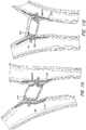
- Figures 12a-12f illustrates several examples of layers having different shapes and connections.
- a molding element may be positioned within the lumen of the braid prior to insertion into the mold to thereby further define the molding surface. If the ends of the tubular metal fabric have already been fixed by a clamp or welding, the molding element may be inserted into the lumen by manually moving the wire strands of the fabric layers apart and inserting the molding element into the lumen of the innermost tubular fabric. By using such a molding element, the dimensions and shape of the finished medical device can be fairly accurately controlled and ensures that the fabric conforms to the mold cavity.
- the molding element may be formed of a material selected to allow the molding element to be destroyed or removed from the interior of the metal fabric.
- the molding element may be formed of a brittle, frangible or friable material. Once the material has been heat-treated in contact with the mold cavities and molding element, the molding element can be broken into smaller pieces, which can be readily removed from within the metal fabric. If this material is glass, for example, the molding element and the metal fabric can be struck against a hard surface, causing the glass to shatter. The glass shards can then be removed from the enclosure of the metal fabric.
- the molding element can be formed of a material that can be chemically dissolved, or otherwise broken down, by a chemical agent that will not substantially adversely affect the properties of the metal wire strands.
- the molding element can be formed of a temperature resistant plastic resin that is capable of being dissolved with a suitable organic solvent.
- the fabric and the molding element can be subjected to a heat treatment to substantially set the shape of the fabric in conformance with the mold cavity and molding element, whereupon the molding element and the metal fabric can be immersed in the solvent. Once the molding element is substantially dissolved, the metal fabric can be removed from the solvent.
- the molding element could be formed of a material having a melting point above the temperature necessary to set the shape of the wire strands, but below the melting point of the strands forming the metal fabric layers.
- the molding element and the layers of metal fabric ultimately comprising the medical device can then be heat treated to set the shape of the metal fabric, whereupon the temperature can be increased to substantially completely melt the molding element, thereby removing the molding element from within the metal fabric.
- the shapes of the mold cavities and the molding elements may be varied in order to produce the medical device having a preselected size and shape.
- the specific shape of a particular molding element produces a specific shape and other molding elements having different shape configurations may be used as desired. If a more complex shape is desired, the molding element and mold may have additional parts including a camming arrangement, but if a simpler shape is being formed, the mold may have few parts. The number of parts in a given mold and the shapes of those parts will be dictated almost entirely by the shape of the desired medical device to which the metal fabric will generally conform.
- the wire strands forming the tubular braids will have a first predetermined relative orientation with respect to one another.
- the fabric layers will tend to flare out away from the axis conforming to the shape of the mold.
- the relative orientation of the wire strands of the metal fabric layers will change.
- the outer and inner metal fabrics will generally conform to the molding surface of the cavity.
- the medical device has a preset expanded configuration and a collapsed configuration which allows the device to be passed through a catheter or other similar delivery device.
- the shape of the fabric layers generally defines the expanded configuration when they are deformed to generally conform to the molding surface of the mold.
- the fabric layers can be subjected to a heat treatment while they remain in contact with the molding surface.
- Heat-treating the metal fabric comprising the plural layers substantially sets the shapes of the wire strands from which they are braided in a reoriented relative position when the fabric layers conform to the molding surface.
- This heat treatment will depend in large part upon the material of which the wire strands of the metal fabric layers are formed, but the time and temperature of the heat treatment should be selected to substantially set the fabric layers in their deformed state, i.e., wherein the wire strands are in their reoriented relative configuration and the fabric layers generally conform to the molding surface.
- the device After the heat treatment, the device is removed from contact with the mold surfaces and will substantially retain its shape in a deformed state. If a molding element is used, this molding element can be removed as described above.
- the time and temperature of the heat treatment can very greatly depending upon the material used in forming the wire strands.
- one preferred class of materials for forming the wire strands are shape memory alloys, with Nitinol, a nickel titanium alloy, being particularly preferred. If Nitinol is used in making the wire strands of the fabric layers, the wire strands will tend to be very elastic when the metal is in its austenitic phase; this very elastic phase is frequently referred to as a super elastic or pseudo elastic phase. By heating the Nitinol above a certain phase transition temperature, the crystal structure of the Nitinol metal will tend to "set" the shape of the fabric layers and the relative configuration of the wire strands in the positions in which they are held during the heat treatment.
- Nitinol wire to set a desired shape
- Spirally wound Nitinol coils for example, are used in a number of medical devices, such as in forming the coils commonly carried around distal links of guide wires and in forming other medical products known in the art.
- a wide body of knowledge exists for forming Nitinol in such devices, so there is no need to go into great detail here on the parameters of a heat treatment for the Nitinol fabric preferred for use in the present invention.
- the device may be used to treat a physiological condition of a patient.
- a medical device suitable for treating the condition which may be substantially in accordance with one of the embodiments outlined below, is selected.
- a catheter or other suitable delivery device may be positioned within a channel in a patient's body to place the distal end of the delivery device adjacent the desired treatment site, such as immediately adjacent (or even within) the shunt of an abnormal opening in the patient's organ for example.
- the delivery device (not shown) can take any suitable shape, but desirably comprises an elongate flexible metal shaft or hypotube or metal braided polymer tube having a threaded distal end for engagement with a threaded bore formed in the clamp of the medical device.
- the delivery device can be used to urge the medical device through the lumen of a catheter / sheath for deployment in a channel of a patient's body. When the medical device is deployed out the distal end of the catheter, the delivery device still will retain it. Once the medical device is properly positioned within the shunt of the abnormal opening, the shaft of the delivery device can be rotated about its axis to unscrew the medical device from the delivery means.
- the occluder device, delivery catheter and catheter /sheath accommodate a coaxial guidewire that slideably passes through the device, end clamps and delivery catheter central lumen, and therefore helps guide the delivery device and outer catheter/ sheath to the desired location.
- the guidewire may be delivered independently through the vasculature and across the targeted treatment location or may be extended partially distal to the distal end of the delivery device and catheter /sheath and advanced with the delivery device and catheter/sheath while the guidewire is manipulated to guide the occluder to the desired location.
- the catheter / sheath is steerable to assist in placement of the delivery device and occluder.
- the operator can retract the device for repositioning relative to the abnormal opening, if it is determined that the device is not properly positioned within the shunt.
- a threaded clamp attached to the medical device allows the operator to control the manner in which the medical device is deployed out the distal end of the catheter.
- the medical device exits the catheter it will tend to resiliently return to a preferred expanded shape, which is set when the fabric is heat-treated.
- the device springs back into this shape it may tend to act against the distal end of the catheter effectively urging itself forward beyond the end of the catheter.
- This spring action could conceivably result in improper positioning of the device if the location of the device within a channel is critical, such as where it is being positioned in a shunt between two vessels. Since the threaded clamp can enable the operator to maintain a hold on the device during deployment, the spring action of the device can be controlled by the operator to ensure proper positioning during deployment.
- the medical device can be collapsed into its reduced diameter configuration and inserted into the lumen of the catheter.
- the collapsed configuration of the device may be of any shape suitable for easy passage through the lumen of a catheter and proper deployment out the distal end of the catheter.
- an ASD occluding device may have a relatively elongated collapsed configuration wherein the devices are stretched along their axes. This collapsed configuration can be achieved simply by stretching the device generally along its axis, e.g. by manually grasping the clamps and pulling them apart, which will tend to collapse the expanded diameter portions of the device inwardly toward the device's axis.
- a PDA occlusion device also operates in much the same fashion and can be collapsed into its collapsed configuration for insertion into the catheter by applying tension generally along the axis of the device.
- these devices are not unlike "Chinese handcuffs", which tend to constrict in diameter under axial tension.
- the device is to be used to permanently occlude a channel in the patient's body, one can simply retract the catheter and remove it from the patient's body. This will leave the medical device deployed in the patient's vascular system so that it may occlude the blood vessel or other channel in the patient's body.
- the medical device may be attached to a delivery system in such a manner as to secure the device to the end of the delivery means. Before removing the catheter in such a system, it may be necessary to detach the medical device from the delivery means before removing the catheter and the delivery means.
- the device will tend to resiliently return to its initial expanded configuration, i.e., its shape prior to being collapsed for passage through the catheter, it should be understood that it might not always return entirely to that shape.
- the device may be desirable that the device has a maximum outer diameter in its expanded configuration at least as large as and preferably larger than, the inner diameter of the lumen of the abnormal opening in which it is to be deployed. If such a device is deployed in a vessel or abnormal opening having a small lumen, engagement with the lumen will prevent the device from completely returning to its expanded configuration. Nonetheless, the device would be properly deployed because it would engage the inner wall of the lumen to seat the device therein.
- thrombi When the device is deployed in a patient, thrombi will tend to collect on the surface of the wires.
- the total surface area of the wires and flow resistance will be increased, increasing the thrombotic activity of the device and permitting it to relatively rapidly occlude the vessel in which it is deployed.
- the occlusion device with the outermost layer being 4 mm diameter tubular braid whose strands are about 0.1 mm (0.004 inch) in diameter and having a pick of at least about 16 (40) and a pitch of at least about 30degrees and surrounding an inner tubular braid whose strands are about 0.025 mm (0.001 inch) and of the same pick and pitch will provide sufficient surface area to substantially completely occlude an abnormal opening or blood vessel of 2 mm to about 4 mm in inner diameter in a very short period of time of less than five minutes. If it is desired to increase the rate at which the device occludes, a third or forth concentrically disposed braided layer can be added. Additionally the device wires may be coated with a thrombogenic coating to aid in the occlusion rate.
- FIGS. 1-4 illustrate a first exemplary medical device 10 for correcting an atrial septal defect (ASD).
- ASD atrial septal defect
- FIGS. 1-4 the device 10 is shown greatly enlarged so that the multiple layers comprising the medical device can be viewed.
- the ASD device is in its relaxed, non-stretched state with two aligned disks 12 and 14 linked together by a short middle cylindrical section 16 ( FIG. 3 ).
- this device 10 may also be well suited in occluding defects known in the art as patent foramen ovale (hereinafter PFO).
- PFO patent foramen ovale
- a device of this configuration may also be suitable for use in a transcatheter closure during a Fenestrated Fontan's procedure.
- ASD is a congenital abnormality of the atrial septum characterized by structural deficiency of the atrial septum.
- a shunt may be present in the atrial septum, allowing flow between the right and left atrial chambers of the heart. In large defects with significant left to right shunts through the defect, the right atrium and right ventricle are volume overloaded and the augmented volume is ejected into a low-resistance pulmonary vascular bed.
- Pulmonary vascular occlusive disease and pulmonary atrial hypertension develops in adulthood.
- Patients with secundum ASD with a significant shunt (defined as a pulmonary blood flow to systemic blood flow ratio of greater than 1.5) are operated upon ideally at two to five years of age or whenever a diagnosis is made in later years.
- a significant shunt defined as a pulmonary blood flow to systemic blood flow ratio of greater than 1.5
- the size of the defect as determined by balloon measurement will correspond to the selected size of the ASD device 10 to be used.
- the device 10 shown in its unconfined or relaxed state in FIGS. 1 and 2 , is adapted to be deployed within the shunt comprising an ASD or a PFO.
- the ASD occluder is sized in proportion to the shunt to be occluded.
- the metal fabric is shaped such that two disk like members 12 and 14 are axially aligned and linked together by the short cylindrical segment 16.
- the length of the cylindrical segment 16 when not stretched preferably approximates the thickness of the atrial septum, and ranges between 3 to 5 mm.
- the proximal disk 12 and distal disk 14 preferably have an outer diameter sufficiently larger than the shunt to prevent dislodging of the device.
- the proximal disk 14 has a relatively flat configuration, whereas the distal disk 12 is preferably cupped towards the proximal end slightly overlapping the proximal disk 14. In this manner, the spring action of the device 10 will cause the perimeter edge 18 of the distal disk to fully engage the sidewall of the septum and likewise an outer edge of the proximal disk 14 will fully engage an opposite sidewall of the septum.
- Perimeter edge 18 of disk 12 as well as the perimeter edge of disk 14 may alternatively be configured with a larger radius outer edge compared to that shown in FIG. 1 , to diminish forces on the tissue abutting the device.
- the exemplary device 10 comprises an outer braided layer 20, a first inner layer 22 and possibly an optional third and innermost layer 24, thereby significantly increasing the wire density without unduly increasing the stiffness of the device or its ability to assume a decreased outer diameter upon longitudinal stretching. Multiple inner layers may be used as needed.
- the ends of the tubular braided metal fabric device 10 are welded or clamped together with clamps as at 26, to avoid fraying.
- the ends of all of the layers may be grouped together and secured by two clamps, one at each end or separate clamps can be applied on each end of the individual layers. Of course the ends may alternately be held together by other means readily known to those skilled in the art.
- the clamp 26 tying together the wire strands of the multiple layers at one end also serves to connect the device to a delivery system.
- the clamp 26 is generally cylindrical in shape and has a recess (not shown) for receiving the ends of the metal fabric to substantially prevent the wires comprising the woven fabric from moving relative to one another.
- the clamp 26 also has a threaded bore 28. The threaded bore is adapted to receive and engage a threaded distal end of a delivery device, such as a pusher wire.
- the exemplary ASD occlusion device 10 can advantageously be made in accordance with the method outlined above.
- the outer layer 20 of device 10 is preferably made from a 0.1-0.2 mm (0.004-0.008 inch) diameter Nitinol wire strands, but lesser or greater diameter strands can be used as well.
- the braiding of the wire mesh comprising the outer layer may be carried out with 11 picks per cm (28 picks per inch) at a shield angle of about 64 degrees using a Maypole braider with 72 wire carriers.
- the braided layers 22 and 24 may each comprise 144 strands of Nitinol wire of a diameter in a range of from 0.025 mm to 0.05 mm (0.001 inch to 0.002 inch), braided at the same pitch.
- the stiffness of the ASD device 100 may be increased or decreased by altering the wire size, the shield angle, the pick rate, and the number of wire carriers or the heat treatment process.
- the cavities of a mold must be shaped consistent with the desired shape of the ASD device. Also, it will be recognized that certain desired configurations may require that portions of the cavities be cammed.
- FIG. 3 illustrates the ASD device 10 in a somewhat longitudinally stretched state. The distance separating the distal and proximal disks 12 and 14 is preferably equal or slightly less than the length of the cylindrical segment 16. The cup shape of each disk 12 and 14, ensures complete contact between the outer edge of each disk 12 and 14 and the atrial septum. Upon proper placement, a new endocardial layer of endothelial cells forms over the occlusion device 10, thereby reducing the chance of bacterial endocarditic and thromboembolisms.
- the distance separating the disks 12and 14 of occluding device 10 may be increased to thereby provide an occluding device suitable for use in occluding a channel within a patient's body, having particular advantages in use as a vascular occlusion device.
- the device 10 includes a generally tubular middle portion 16 and a pair of expanded diameter portions 12 and 14. The expanded diameter portions are disposed at either end of the generally tubular middle portion. The relative sizes of the tubular middle section 16 and the expanded diameter portions 12-14 can be varied as desired.
- the medical device can be used as a vascular occlusion device to substantially stop the flow of blood through a patient's blood vessel.
- the device 10 When the device 10 is deployed within a patient's blood vessel, it is positioned within the vessel such that its longitudinal axis generally coincides with the axis of the vessel segment in which it is being inserted.
- the dumbbell shape is intended to limit the ability of the vascular occlusion device to turn at an angle with respect to the axis of the blood vessel to ensure that it remains in substantially the same position in which the operator deploys it within the vessel.
- the maximum diameter of the expanded diameter portions 12-14 should be selected so that it is at least as great as the diameter of the lumen of the vessel in which it is to be deployed and is optimally slightly greater than that diameter.
- the vascular occlusion device When it is deployed within the patient's vessel, the vascular occlusion device will engage the lumen at two spaced apart locations. The device is desirably longer along its axis than the dimensions of its greatest diameter. This will substantially prevent the vascular occlusion device 10 from turning within the lumen at an angle to its axis, essentially preventing the device from becoming dislodged and tumbling along the vessel within the blood flowing through the vessel.
- the relative sizes of the generally tubular middle portion 16 and expanded diameter portions 12-14 of the vascular occlusion device can be varied as desired for any particular application by appropriate selection of a mold to be used during the heat setting of the device.
- the outer diameter of the middle portion 16 may range between about 1/4 and about 1/3 of the maximum diameter of the expanded diameter portions and the length of the middle portion 16 may comprise about 20% to about 50% of the overall length of the device 10.
- these dimensions are suitable if the device is to be used solely for occluding a vascular vessel, it is to be understood that these dimensions may be varied if the device is to be used in other applications, such as a ventricular septal defect occluder (VSD).
- VSD ventricular septal defect occluder
- the aspect ratio (i.e., the ratio of the length of the device over its maximum diameter or width) of the exemplary device 10 illustrated is desirably at least about 1.0, with a range of about 1.0 to about 3.0 being preferred and then aspect ratio of about 2.0 being particularly preferred. Having a greater aspect ratio will tend to prevent the device 10 from rotating generally perpendicularly to its axis, which may be referred to as an end-over-end roll.
- the outer diameter of the expanded diameter portions 12-14 of the device 10 is large enough to seat the device fairly securely against the lumen of the channel in which the device is deployed, the inability of the device to turn end-over-end will help keep the device deployed precisely where it is positioned within the patient's vascular system or in any other channel in the patient's body.
- having expanded diameter portions 12-14 which have natural relaxed diameters substantially larger than a lumen of the vessels in which the device is deployed should also suffice to wedge the device into place in the vessel without undue concern being placed on the aspect ratio of the device.
- PDA patent ductus arteriosus
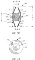
- the PDA device 100 has a generally bell-shaped body 102 and an outwardly flaring forward end 104.
- the bell-shaped body 102 is adapted to be positioned within the aorta to help seat the body of the device in the shunt.
- the body 102 and the end portion 104 can be varied as desired during manufacture to accommodate different sized shunts.
- the body 102 may have a diameter along its generally slender middle of about 10 mm and a length along its axis of about 25 mm.
- the base of the body may flare generally radially outward until it reaches an outer diameter equal to that of the forward end 104 which may be on the order of about 20 mm in diameter.
- the base 106 desirably flares out relatively rapidly to define a shoulder 108, tapering radially outwardly from the body 102.
- This shoulder 108 will abut the perimeter of the lumen being treated with higher pressure.
- the forward end 104 is retained within the vessel and urges the base of the body 102 open to ensure that the shoulder 108 engages the wall of the vessel to prevent the device from becoming dislodged from within the shunt.
- An exemplary PDA occlusion device 100 can advantageously be made in accordance with the method outlined above, namely deforming multiple layers 110, 112 and 114 ( FIG.
- the outer layer 110 comprises a frame that defines the outer shape of the medical device 100. It is preferably formed from 72 or 144 braided strands whose diameters are in a range of from 0.076 mmto about 0.20 mm (0.003 to about 0.008 inch). The pitch of the braid may be variable. Within this frame is the layer 112 that forms an outer liner. It may also prove expedient to incorporate a third layer 114 as an inner liner.
- the outer and inner liners may be braided using 144 strands of a shape memory wire whose diameter may be 0.025 mm to 0.05 mm (0.001 to 0.002 inch).
- the pitch of the braid in layers 112 and 114 should be the same.
- the ends 116 and 118 of the braided layers should be secured in order to prevent the braids from unraveling.
- clamps 120 are used to tie together the respective ends of the wire strands on each end 116 and 118 of the tubular braid members forming the occlusion device 100.
- different clamps may be used to secure the ends of the metal strands of the outer fabric layer than are used to secure the ends of the metal strands of each of the inner layers.
- clamps 120 of the outer layer may include a threaded bore 122 that serves to connect the device 100 to a delivery system (not shown).
- the clamps 120 are generally cylindrical in shape and have a crimping recess for receiving the ends of the wire strands to substantially prevent the wires from moving relative to one another.
- the strands When using untreated NiTi fabrics, the strands will tend to return to their unbraided configuration and the braided layers 110, 112 and 114 can unravel fairly quickly unless the ends of the length of the braided layers that are cut to form the device are constrained relative to one another.
- the clamps 120 are useful to prevent the layers of braid from unraveling at either end.
- soldering and brazing of NiTi alloys has proven to be fairly difficult, the ends can be welded together, such as by spot welding with a laser welder.
- the individual strands will tend to return to their heat set configuration unless constrained. If the braid is heat treated to set the strands in the braided configuration, they will tend to remain in the braided form and only the ends will become frayed. However, it may be more economical to simply form the braid without heat-treating the braid since the fabric will be heat treated again in forming the medical device.
- the fabric layers can be subjected to a heat treatment such as is outlined above.
- a heat treatment such as is outlined above.
- the formed device 100 can be collapsed, such as by urging the clamps 120 generally axially away from one another, which will tend to collapse the device 100 toward its axis.
- the collapsed device can then be attached to a delivery device, such as an elongated flexible push wire and passed through a delivery catheter for deployment in a preselected site in the patient's body.
- a delivery device such as an elongated flexible push wire and passed through a delivery catheter for deployment in a preselected site in the patient's body.
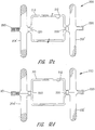
- FIGS 8-10 show exemplary vascular plug arrangements. These plugs are ideally suited for treating a variety of arterial-venous malformations and aneurysms. These plugs can also be used to block blood flow to a tumor or lesion. Likewise, these plugs can be used to bloc fluid flow through a portion of the vasculature of the body in connection with the treatment of other medical conditions.
- Each exemplary vascular plug shown in Figures 8-10 has a multi-layered braided structure 150, i.e., two or more layers of braided fabric.
- a pair of end clamps 152 and 154 are provided to prevent the multi-layered braided structure from unraveling.
- Those skilled in the art will recognize that only a single end clamp is required if the braids are in the form of a sack as opposed to having a tubular shape.
- the device shown in Figure 8 has a cylindrical wall 155 with two faces 156 and 158 at the opposite ends.
- the cylindrical wall abuts the wall of the vessel in which the device is deployed to hold the device in place.
- the two faces 156 and 158 preclude fluid flow past the device.
- the device shown in Figure 9 also has a cylindrical wall 155, a proximal face 156 and a distal face 158.
- the exemplary vascular plug of Figure 9 further provides an intermediate clamp 160 clamping an intermediate portion of the multi-braided material. This divides the cylindrical wall into two sections 155a and 155b and forming two additional faces 162 and 164.
- the two sections 155a and 155b of cylindrical wall 155 still abuts the vessel wall to hold the device in place yet fluid must to traverse all for faces (namely faces 156, 158, 162 and 164) to flow past the device.
- the reduction in flow provided by the two additional faces 162 and 164 can result in faster clotting.
- Figure 10 shows the same basic structure as Figure 9 .
- the primary difference is that the application of the intermediate clamp 160 results in the two sections 155a and 155b having a bulbous rather than a cylindrical form.
- the widest part of sections 155a and 155b still engage the vessel wall and hold the device in place after deployment.
- the intermediate clamp 160 can be made of any suitable material. Suture thread has proven to be effective.
- the two end clamps 152 and 154 are preferably made of a radiopaque material so they can easily be visualized using, for example, a fluoroscope.
- the intermediate clamp can be made of such material as well.
- additional intermediate clamps can be added to further increase the number of faces. For example, if two intermediate clamps are used, a total of six faces would be present. With each additional clamp, two additional faces are provided.
- the multi-layered braided structure (or at least one of the layers thereof) is made of a super elastic or shape memory material
- a shape e.g., a shape such as that shown in Figure 8
- all such exemplary vascular plugs including those shown in Figures 8-10 , are deformable to a lesser cross-sectional dimension for delivery through a catheter.
- FIG. 11a-11d An embodiment according to the invention for the treatment of Patent Ductus Arteriosus (PDA) is shown is Figures 11a-11d .
- the following dimensions are given in relation to the typical size range for PDA pediatric passageways and not intended as a limitation..
- the PDA occlusion device 200 of this embodiment of the invention can advantageously be made in accordance with the exemplary method outlined above, namely deforming multiple layers 210, and 212 of generally concentrically oriented tubular metal fabric to conform to a molding surface of a mold and heat-treating the fabric layers to substantially set the fabric layers in their deformed state.
- the at least two layers of braid in this device have the same molded shape.
- the occlusion device 200 has two disks 202, 204, one at each end that has an outer portion, starting at diameter C and extending to diameter B, tapered toward the device center at an angle F that ranges from 20 to 40 degrees, preferably 30 degrees.
- Each disk has a central portion 206 that is perpendicular to the device 200 central axis and extends outward to a diameter C that ranges from 3mm to 6mm.
- Each disk is a mirror image of the other disk with an outer diameter B that ranges from 9mm to 12mm.
- the disks are thin with the disk wall essentially little more than the thickness of the 2 layers formed back to back, ranging from 0.127 mm to 0.254 mm (.005 to .010 inch) preferably 0.178mm (.007 inch) or a double wall thickness (4 layers) of 0.356 mm (.014inch).
- the device 200 includes a central cylindrical portion 214 of diameter C which ranges from 2mm to 6mm.
- the length of the cylindrical central section A ranges from 2mm to 8mm.
- a very reduced diameter E which ranges from 1mm to 2mm, preferably 1mm (or a tightly bunched group of wires).
- the ratio of the large disk diameter B to the small diameter E ranges from 6 to 12.
- Figure 11c-11f illustrates a condition where the disks 202, 204 are relatively parallel but at a substantial angle to the central section or device axis. The central section is elongated due to a smaller passage than anticipated and the elongation accommodates the lengthen passage between disks.
- Figure 11d the disks are non-parallel to accommodate the walls of the aorta and again the central section is elongated as it conforms to the passageway between the disks.
- Figure 11e illustrates a device placed in a para- membranous VSD.
- FIG. 11f shows a device placed in a tear through a ventricular septum.
- the device central section 214 elongates to fill the tear and the disks conform to the septum walls.
- the ratio of diameters B to E and C to E allows both the disks and central cylindrical portion to articulate about diameter E at an angle to the device axis and to conform more easily to vessel passageway variability and tissue irregularity at the disk contact area.
- Diameter C is selected to be a little larger (10-20%) than the passageway it is intended for, to provide some anchoring of the device. If the passageway is longer than anticipated the central portion can elongate to accommodate the longer length.
- the disks are spaced apart at there outermost point a distance D that ranges from 1mm to 3mm, preferably 1mm.
- the distance between the inner surface of each disk, in the portion (C) perpendicular to the device central axis, is G and ranges from 3 to 7mm, preferably 5mm.
- the difference between distance G and A provides for passageway length variability and conformability to surface irregularities as well as acts like a spring to apply clamping pressure at each disk to the vessel to hold the device in place.
- the outer layer 210 comprises a frame that defines the outer shape of the medical device 200. It is preferably formed from 72 braided strands whose diameters are in a range of from 0.025 mm to about 0.127 mm (0.001 to about 0.005 inch), preferably 0.038 mm (.0015 in). The pitch of the braid ranges from 45 to 70 degrees, preferably 60 degrees.
- the inner layer 212 having the same shape as outer layer 210.
- the inner layer is preferably braided using 144 strands of a shape memory wire whose diameter may be 0.025 mm to 0.076 mm (0.001 to 0.003 in), preferably 0.038 mm (.0015 in).
- the pitch of the braid in layers 210 and 212 are preferably the same but can also be different without departing from the scope of the invention.
- the ends 216 and 218 of the braided layers should be secured in order to prevent the braids from unraveling.
- clamps 220 made from platinum-iridium or stainless steel, are used to tie together the respective ends of the wire strands on each end 216 and 218 of the tubular braid members forming the occlusion device 200.
- the clamps 220 are preferably oriented outward from the disks as shown in Figure 11 a but may alternatively be recessed within the disk surface somewhat, although full recess of the clamps would require a recess in the central portion end walls and the disk walls to accommodate the clamp length.
- clamps may be used to secure the ends of the metal strands of the outer fabric layer than are used to secure the ends of the metal strands of each of the inner layers. It is to be understood that other suitable fastening means may be attached to the ends in other ways, such as by welding, soldering, brazing, use of biocompatible cementious material or in any other suitable fashion.
- One or both clamps 220 may include a threaded bore 222 that serves to connect the device 200 to a delivery system (not shown).
- the clamps 220 are generally cylindrical in shape and have a crimping recess for receiving the ends of the wire strands to substantially prevent the wires from moving relative to one another.
- the strands When using untreated NiTi fabrics, the strands will tend to return to their unbraided configuration and the braided layers 210, and 212 can unravel fairly quickly unless the ends of the length of the braided layers that are cut to form the device are constrained relative to one another.
- the clamps 220 are useful to prevent the layers of braid from unraveling at either end. Although soldering and brazing of NiTi alloys has proven to be fairly difficult, the ends can be welded together, such as by spot welding with a laser welder. When cutting the fabric comprising the multiple layers 210, and 212 to the desired dimensions, care should be taken to ensure that the fabric layers do not unravel.
- the individual strands will tend to return to their heat set configuration unless constrained. If the braid is heat treated to set the strands in the braided configuration, they will tend to remain in the braided form and only the ends will become frayed. However, it may be more economical to simply form the braid without heat-treating the braid since the fabric will be heat treated again in forming the medical device.
- the clamps 220 may comprise two concentric rings with the braid wires constrained between the rings, by either using the previous described methods or by swaging the outer ring against the wires and the inner ring.
- the use of an inner ring in the clamps 220 provides a central lumen for slidable passage of the guidewire.
- the treaded clamp can either use internal threads (inner ring) or external threads (outer ring), provided that a passage for the guidewire is present.
- the fabric layers can be subjected to a heat treatment such as is outlined above.
- a heat treatment such as is outlined above.
- the formed device 200 can be collapsed, such as by urging the clamps 220 generally axially away from one another, which will tend to collapse the device 200 toward its axis.
- the collapsed device can then be attached to a delivery device, such as an elongated flexible push wire and passed through a delivery catheter for deployment in a preselected site in the patient's body.
- a delivery device such as an elongated flexible push wire and passed through a delivery catheter for deployment in a preselected site in the patient's body.
- Figures 12a-12f Other alternative embodiments are shown diagrammatically in Figures 12a-12f .
- Each of the designs incorporate the beneficial features, range of dimensions, fabric selection, etc., of the prior embodiments and exemplary occlusion devices except as noted.
- Figure 12a the disks 202' and 204' are fabricated from a single layer folded back on itself, while the central portion is double layered. In this case the pitch of the inner layer would have to be increased relative to the outer layer so that both layers had the same collapsed length. This gives flexibility to the designer to have different characteristics in the disk portion relative to the central portion of the device.
- Figure 12f shows an embodiment where the design is reversed to have double layers in the disk portion back to back, with a single layer in the central portion or a different shape for each layer in the central portion as shown.
- Figure 12b illustrates a design variation where the multiple braid layers have end wires connected at one end in a common clamp but where the inner layer at the opposite end has a clamp that free floats and is separate from the clamp for the outer layer.
- this design there is freedom to have different compressed braid lengths so that the pitch may be varied as desired.
- the inner layer could also follow the shape of the outer layer in entirety if desired with a different pitch between layers.
- the inner layer 212 is suspended by suture connectors between the layers and the end clamps of each layer are independent of each other.
- the inner layer 212 has independent end clamps as in Figure 12c , but rather than the layers connected by sutures, the layers 210 and 212 have their end clamps connected by elastic members, such as made from silicone rubber.
- Figure 12e is similar to Figure 12d except that the connector could be a non-elastomer such as suture or wire and may be connected optionally at only one set of end clamps. All embodiments shown in Figures 12a-12f have a relatively small diameter E in comparison to diameters B and C to maintain the articulation benefits. Diameters A, B, C and E are defined as in Figure 11a . It is anticipated that the various optional characteristics, as shown in Figures 12a-12f , could be combined in any manner desired for any embodiment described herein.
- FIG. 13a-13f Various exemplary occlusion devices for treating Para-Valvular Leaks (PVL) are illustrated in Figures 13a-13f .
- Figure 13a shows an artificial bi-leaflet valve sewn by suture 232 into a patient.
- Three cross-hatched areas 234, 236 and 238 along the valve cuff represent open areas where tissue has pulled away from the cuff from weak tissue or broken or loose sutures. These open areas allow blood to short circuit the valve and result in poor heart function and lower blood pressure.
- the exemplary occlusion device herein is designed to close /occlude these PVLs such as are shown in Figures 13a-13f .
- An exemplary PVL occlusion device 300 can advantageously be made in accordance with the method outlined above, namely deforming multiple layers 310, 312 of generally concentrically oriented tubular metal fabric to conform to a molding surface of a mold and heat-treating the fabric layers to substantially set the fabric layers in their deformed state.
- the outer layer 310 comprises a frame that defines the outer shape of the medical device 300. It is preferably formed from 144 braided strands whose diameters are in a range of from 0.038 mm to about 0.089 mm (.0015 to about .0035 inch) preferably 0.051 mm (.002inch).
- the pitch of the braid may range from 45 to 70 degrees, preferably 60 degrees.
- the inner layer 312. It may also prove expedient to incorporate a third layer 314 (not shown) as an innermost liner.
- the inner layer may be braided using 144 strands of a shape memory wire whose diameter ranges from 0.025 mm to 0.051 mm (.001 to .002 inch), preferably 0.038 mm (.0015inch).
- the pitch of the braid in layers 310 and 312 preferably are the same.
- the ends 316 and 318 of the braided layers should be secured in order to prevent the braids from unraveling.
- clamps 320 are used to tie together the respective ends of the wire strands on each end 316 and 318 of the tubular braid members forming the occlusion device 300.
- different clamps may be used to secure the ends of the metal strands of the outer fabric layer than are used to secure the ends of the metal strands of each of the inner layers.
- Other suitable fastening means may be attached to the ends in other ways, such as by welding, soldering, brazing, use of biocompatible cementious material or in any other suitable fashion.
- One or both clamps 320 of the outer layer may include a threaded bore 322 that serves to connect the device 300 to a delivery system (not shown).
- the clamps 320 are generally cylindrical in shape and have a crimping recess for receiving the ends of the wire strands to substantially prevent the wires from moving relative to one another.
- the strands When using untreated NiTi fabrics, the strands will tend to return to their unbraided configuration and the braided layers 310, and 312 can unravel fairly quickly unless the ends of the length of the braided layers that are cut to form the device are constrained relative to one another.
- the clamps 320 are useful to prevent the layers of braid from unraveling at either end. Although soldering and brazing of NiTi alloys has proven to be fairly difficult, the ends can be welded together, such as by spot welding with a laser welder. When cutting the fabric comprising the multiple layers 310, and 312 to the desired dimensions, care should be taken to ensure that the fabric layers do not unravel.
- the individual strands will tend to return to their heat set configuration unless constrained. If the braid is heat treated to set the strands in the braided configuration, they will tend to remain in the braided form and only the ends will become frayed. However, it may be more economical to simply form the braid without heat-treating the braid since the fabric will be heat treated again in forming the medical device.
- device 300 is formed of two layers each having the same shape.
- Figure 13b-II is a plan view of device 300 and Figure 13b-III is an end view thereof. This particular design is intended to occlude openings that are somewhat oblong in shape.
- Radiopaque markers 330 may be placed either on the narrow or wide side of the expanded shape to help the physician orient the device as needed.
- markers may be radiopaque platinum wire or platinum iridium markers attached to the braid in manner which does not impede braid collapse or self expansion. Since the wire diameter is small, the oblong shape can conform to shapes that may be more rounded or longer.
- Figure 13c illustrates a crescent shaped occluder 324 and Figure 13d illustrates a round occluder 326.
- one edge of the device that interfaces with the cuff 240 is shaped to match the cuff shape whereas the other side that interfaces with the tissue 242 has a shape more conducive to the thickness of the tissue at the interface.
- dimensions are given for the oblong occluder of Figure 13b but are similar for other shapes where applicable. All dimensions are in mm.
- FIG 13f a preferred clamp 320 for the device 300 intended to be compatible with delivery of the occluder over a guidewire.
- the clamps 320 must have a central passage 328 for the guidewire to slidable pass there through.
- the clamp 320 is therefore fabricated with an inner ring 330 having an inside diameter slightly larger (about 0.05-0.01mm (.002-.004 inch)) larger than the guidewire diameter.
- the clamp also has an outer ring 332 large enough to contain the braided wire ends between the two rings.
- the outer ring may be swaged to compress the outer ring against the wires and the inner ring or the wire ends and rings may be welded, brazed, soldered or held by adhesive or other known means.
- At least one of the clamps has threads either external on the outer ring of the clamp or internally in the inner ring. If internal threads are used the inner ring must be enlarged to accommodate a male threaded delivery device with an internal lumen sized for passage of a guide wire through the threaded clamp.
- An over the guidewire delivery system is particularly useful in delivery of an occluder for PVL cases.
- One of the most difficult aspects of the case is delivering the device through the defect near the valve cuff. Due to the turbulence of blood in the area of the valve it is preferable to place a small surface area steerable guidewire through the defect first and then advance the delivery device and catheter over the guidewire.
- the guidewire may be placed through the catheter and delivery device and lead the passage of the system through the vasculature. Near the valve defect the guidewire may be independently maneuvered through the defect and then the catheter and delivery device may be advanced over the guidewire.
- An exemplary method of treating a pera-valular leak may involve the following steps: (1) advance a guidewire through the vasculature of the body and across the pera-valular leak opening; (2) advance over the guidewire a catheter containing a occluder connected to a delivery device until the distal tip of the catheter crosses the pera valular leak opening; (3) deploy the distal portion (distal to waist) of the occluder by manipulating the deliver device to extend the distal portion of the occluder beyond the distal end of the catheter causing the distal portion to self expand toward it's preset shape; (4) pulling proximally the catheter and delivery device until the expanded portion of the occluder contacts tissue adjacent one side of the opening; (5) withdrawing the catheter proximally relative to the delivery device, to expose the remaining proximal portion of the occluder while allowing the deliver device to advance distally as the occluder self expands and contacts tissue adjacent the opposite side of the opening; (6) disconnecting the delivery device from the occ
- An alternative exemplary method of treating a pera- valvular leak is similar to above but includes the step of: advancing the guidewire through the vasculature through a preshaped or steerable catheter to facilitate passage through the peri-valvular leak opening.
- An optional additional step includes: removing the catheter after crossing the leak opening and before delivery of the occluder.
- FIG. 14a-14c Another exemplary occlusion device is a variation of the devices shown in Figures 12a-12f , whereby the occluder device 400, as shown in Figures 14a-14c , consists of a soft, conformable, outer braid 410 enclosing a volume 430 that is pre-shaped as desired, with two or more internal braided tubular members 412a, b, c side by side with shared braid end wire connectors at least at one end.
- the multiple braids need not be concentric. This arrangement allows the inner braided members 412 to shift relative to one another to fill the available volume of unknown size or shape such as an oblong, crescent, or oval cavity shape.
- the proximal clamp 420 at wire end 418 contains threads (not shown) for connection to the delivery catheter, not shown.
- the proximal clamp 420 may or may not also clamp the ends of the inner braid proximal wire ends.
- proximal wire ends of braids 412 be connected to clamp 420 by means of a tether or elastic member to allow for a braid length change that would vary based on the shape of the device 400 within a cavity.
- the outer braid for this exemplary occluder could be a braid of 144 Nitinol wires of a diameter of between 0.025 - 0.05 mm (.001 -.002 inches).
- the inner braids may be fashioned from either 72 or 36. Nitinol wires with a diameter of 0.025-0.076 mm (.001-.003 inches).
- An optional over the exemplary guidewire delivery device is practical by using wire end clamps 420 that are of the two ring design as described in previous examples.
- the outer braid 510 is pre-shaped to define a particular volume shape 530.
- Contained within the outer braid and coaxially sharing the outer braid distal wire end clamp 520 is a smaller diameter tubular braid 512 that is pre-shaped into a bead and chain shape.
- the internal smaller braid 512 is much longer than the outer braid 510 and is designed to meander into the outer braid defined volume 530 as braid 512 is inserted to fill the volume completely and help the outer braid to conform to the cavity shape it is within.
- the distal braided wire end clamp 520 at wire end 516 is preferably a two part clamp arrangement with an internal ring and external ring pinching the braid wires between the rings.
- the proximal braided wire end clamp 522 is similarly constructed but the outer ring is threaded to mate with threads on the delivery catheter 540 for selective connection between the device and the delivery catheter. In this exemplary device a portion of the inner braid remains within the delivery catheter when the outer braid is fully deployed.
- a pusher wire 528 within the delivery catheter 540 acts against the proximal end wire end clamp 523 of braid 512 to advance the braid completely out of the delivery catheter.
- the pusher wire 528 may optionally have a threaded end to engage with optional threads in the wire end clamp 523.
- the delivery catheter 540 would be advanced to the treatment site through a sheath.
- the high density of wire within the volume 530 aids in rapid hemostasis while maintaining a low profile for delivery.
- the spherical shape of the bead chain fills the volume with sphere against sphere against the outer braid and thereby loads the outer braid surface against the cavity wall desired to be occluded.
- the outer braid should be soft and conformable.
- a braid of 144 Nitinol wires of 0.025 - 0.05 mm (.001- .002 inch) diameter should be suitable.
- the inner braid may be either 72 or 36 Nitinol wires and the wire diameter may be between 0.025 mm to 0.76 mm (.001 to .003 inch).
- the outer and inner braided layers are heat set as previously described in the desired volume shape and beaded chain shape as desired.
- the wire end clamps 520 and 523 may be of the two ring configuration as previously described in other exemplary occluders to allow the device to be configured for over the guidewire delivery.
- An exemplary method of occluding a body cavity consists of the following steps: (1) providing an occluder comprising at least a first self expanding braided tubular layer defining a preset volume shape and a second braided member longer than the first braided member in the collapsed for delivery configuration, the second braided member coaxially connected at one end to the end of the first braided layer, the second braided member having a repeating preset volume occupying shape much smaller than the preset shape of the first braided layer, whereby both first and second braided members have a collapsed elongated low profile shape for delivery through a catheter and a self expanding preset volume occupying space for occlusion of a body cavity; (2) advancing the distal tip of a delivery catheter containing the occluder and a delivery device to a body cavity; (3) advancing the distal end of the occluder out of the catheter to allow the occluder first braided layer to self expand within the cavity; advancing the second
- the device central diameter is relieved with a flattened or inverted portion in the circumference to relieve pressure on the heart's conductive His bundle at the muscular portion of the septum, to prevent heart block ( Figure 16a ).
- the device has only one articulating flange 600 (right chamber) with a small diameter E and the flange 602 on the opposing end (left chamber) is relieved in diameter to prevent interference with the aortic valve.
- FIG. 16d discloses an exemplary occlusion device, which does not form part of the invention, wherein both flange articulations have been eliminated.
- the central portion could alternatively be barrel shaped, spherical, or cylindrical in outer surface with straight or tapered end walls.
- the central portion may be bellows shaped to further accommodate passage length change, double cone shaped with a center point at the maximum diameter or any other shape as desired.
- the disks need not be tapered inward but this is preferred.
- the disks may be preformed in a non parallel manner and one disk may be of a size different from the other.
- this design is preferably 2 layers it is also anticipated that additional layers (3, 4, or more) may be used to fabricate the device. Also, the layers may be the same pick count and the same wire diameter or they may be varied in any order or manner as suited to a particular application.
- the preferred embodiment described occludes relatively quickly compared to prior art devices due the small pore size and large surface area created by the multitude of wires in multiple layers, has a lower profile, improved retention force, and improved conformability to adjust to a variety of vessel passageways with minimal interference in the native vessel flow.
- the reduced profile of this device is sufficiently low to allow delivery through a 4 French catheter or sheath.
- the device 200 is also symmetrical so that is may be deliverable by catheter from either the pulmonary side or the aortic side as selected by the physician.
- the advantage of a venous approach for PDA closure is to potentially treat infants as small a 1kg.
- the advantage of an arterial approach in slightly larger premature infants is that both angiography and device implant can take place from a common access point in the femoral artery.
Claims (27)
- Dispositif médical repliable (200) comprenant un segment central cylindrique (214) et des segments d'extrémité distal et proximal (202, 204), chacun desdits segments (214 ; 202, 204) ayant une pluralité de brins métalliques tressés présentant une configuration préétablie déployée où les segments d'extrémité distal et proximal (202, 204) comprennent des éléments de disque ayant des diamètres (« B ») supérieurs à celui du segment central (« C »), les éléments de disque étant fixés d'un seul tenant à des extrémités opposées du segment central (214), un ou deux éléments de disque étant fixés par des segments de raccordement d'un diamètre (« E ») inférieur à celui du segment central (« C »), moyennant quoi l'élément de disque et le segment central (214) peuvent s'articuler autour du segment de raccordement, le segment central (214) entourant une couche cylindrique intérieure (212) de brins métalliques tressés.
- Dispositif médical repliable selon la revendication 1, dans lequel les éléments de disque sont fixés d'un seul tenant à des extrémités opposées du segment central (214) par des segments de raccordement d'un diamètre (« E ») inférieur à celui du segment central (« C »), de sorte que les deux éléments de disque et le segment central (214) puissent s'articuler autour des segments de raccordement.
- Dispositif médical selon la revendication 1 et comportant en outre un moyen (220) apposé sur les segments d'extrémité distal et proximal (202, 204) pour empêcher un effilochage des brins métalliques tressés.
- Dispositif médical selon la revendication 1, dans lequel le pas des brins métalliques tressés comprenant le segment central cylindrique (214) et la couche cylindrique intérieure (212) est un pas inégal.
- Dispositif médical selon la revendication 1, comportant en outre un moyen d'arrimage du segment central cylindrique (214) à la couche cylindrique intérieure (212).
- Dispositif médical selon la revendication 5, dans lequel le moyen d'arrimage comprend un lien de suture.
- Dispositif médical selon la revendication 3 et comportant en outre un moyen séparé du moyen (220) apposé sur les segments d'extrémité distal et proximal (202, 204) pour empêcher un effilochage de la couche cylindrique intérieure (212) de brins métalliques tressés.
- Dispositif médical repliable selon la revendication 1, dans lequel le segment central cylindrique (214), les segments d'extrémité distal et proximal (202, 204) et les un ou plusieurs segments de raccordement comprennent une couche d'étoffe tubulaire extérieure entourant au moins une couche d'étoffe intérieure (212), chaque couche comprenant une pluralité de brins métalliques tressés.
- Dispositif médical repliable selon la revendication 8, comportant en outre une troisième étoffe métallique, ladite troisième étoffe métallique comprenant une pluralité de brins métalliques tressés.
- Dispositif médical repliable selon la revendication 8, dans lequel les éléments de disque peuvent s'articuler de façon à être non parallèles.
- Dispositif médical repliable selon la revendication 8, dans lequel au moins l'un des segments d'extrémité (202, 204) comprend une surface non plane.
- Dispositif médical repliable selon la revendication 8, dans lequel la configuration préétablie déployée est déformable en une dimension en coupe moindre pour administration à travers un canal dans le corps d'un patient, les couches d'étoffe ayant une propriété de mémoire de sorte que le dispositif médical (200) tende à retourner à la configuration préétablie déployée lorsqu'il est non contraint.
- Dispositif médical repliable selon la revendication 8, dans lequel le dispositif peut être administré via un cathéter français de taille 4.
- Dispositif médical repliable selon la revendication 8, dans lequel le dispositif peut être administré sur un fil guide.
- Dispositif médical repliable selon la revendication 8, dans lequel les couches sont assemblées l'une à l'autre.
- Dispositif médical repliable selon la revendication 15, dans lequel les extrémités de la pluralité de brins tressés sont assemblées les unes aux autres au niveau d'une extrémité avec une pince ou une soudure (220) de façon à empêcher les couches intérieure (212) et extérieure de s'effilocher.
- Dispositif médical repliable selon la revendication 8, dans lequel les brins métalliques tressés comprennent du Nitinol.
- Dispositif médical repliable selon la revendication 8, dans lequel les couches d'étoffe intérieure (212) et extérieure sont disposées en agencement coaxial concentrique.
- Dispositif médical repliable selon la revendication 8, dans lequel les couches d'étoffe intérieure (212) et extérieure ont des extrémités proximale et distale, et dans lequel les couches d'étoffe intérieure (212) et extérieure sont totalement disposées en couches l'une par rapport à l'autre entre leurs extrémités proximale et distale.
- Dispositif médical repliable selon la revendication 8, dans lequel chacune des couches d'étoffe intérieure (212) et extérieure comprend un élément tubulaire (214) ayant des extrémités proximale et distale et un axe central s'étendant entre elles, et dans lequel l'élément tubulaire (214) de la couche d'étoffe extérieure entoure totalement l'élément tubulaire de la couche d'étoffe intérieure (212) de l'extrémité proximale à l'extrémité distale le long de l'axe central.
- Dispositif médical repliable selon la revendication 8, dans lequel le dispositif (200) est symétrique de sorte que le dispositif soit configuré pour être administrable depuis le côté veineux ou artériel du même défaut.
- Dispositif médical repliable selon la revendication 8, dans lequel le rapport entre un diamètre (« B ») de l'au moins un segment d'extrémité (202, 204) et un diamètre (« E ») de l'au moins un segment de raccordement va de 6 à 12.
- Dispositif médical repliable selon la revendication 8, dans lequel l'au moins une couche intérieure (212) comprend des segments d'extrémité proximal et distal, un segment central et au moins un segment de raccordement qui sont formés d'un seul tenant à partir d'une pluralité de brins métalliques tressés.
- Dispositif médical repliable selon la revendication 8, dans lequel la couche d'étoffe extérieure et l'au moins une couche d'étoffe intérieure (212) sont indépendantes l'une de l'autre.
- Dispositif médical repliable selon la revendication 8, dans lequel chacune des couches d'étoffe intérieure (212) et extérieure comprend un élément tubulaire ayant des extrémités proximale et distale correspondant aux extrémités de la pluralité de brins tressés, et dans lequel les extrémités proximales de chaque élément tubulaire sont couplées les unes aux autres et les extrémités distales de chaque élément tubulaire sont couplées les unes aux autres de façon à empêcher les couches intérieure et extérieure de s'effilocher.
- Dispositif médical repliable selon la revendication 8, dans lequel chacune des sections d'extrémité est en forme de disque et est une image miroir de l'autre.
- Dispositif médical repliable selon la revendication 8, dans lequel le rapport entre le diamètre extérieur (« C ») du segment central (214) et le diamètre extérieur (« E ») du segment de raccordement est dans la plage de 2 à 6.
Priority Applications (1)
| Application Number | Priority Date | Filing Date | Title |
|---|---|---|---|
| EP17159943.4A EP3202333B1 (fr) | 2007-06-21 | 2007-10-03 | Structures tressées multicouche pour l'occlusion de défauts vasculaires |
Applications Claiming Priority (1)
| Application Number | Priority Date | Filing Date | Title |
|---|---|---|---|
| US11/820,841 US8777974B2 (en) | 2004-03-19 | 2007-06-21 | Multi-layer braided structures for occluding vascular defects |
Related Child Applications (2)
| Application Number | Title | Priority Date | Filing Date |
|---|---|---|---|
| EP17159943.4A Division-Into EP3202333B1 (fr) | 2007-06-21 | 2007-10-03 | Structures tressées multicouche pour l'occlusion de défauts vasculaires |
| EP17159943.4A Division EP3202333B1 (fr) | 2007-06-21 | 2007-10-03 | Structures tressées multicouche pour l'occlusion de défauts vasculaires |
Publications (3)
| Publication Number | Publication Date |
|---|---|
| EP2014239A2 EP2014239A2 (fr) | 2009-01-14 |
| EP2014239A3 EP2014239A3 (fr) | 2012-01-25 |
| EP2014239B1 true EP2014239B1 (fr) | 2017-04-26 |
Family
ID=39367069
Family Applications (2)
| Application Number | Title | Priority Date | Filing Date |
|---|---|---|---|
| EP07253907.5A Active EP2014239B1 (fr) | 2007-06-21 | 2007-10-03 | Structures tressées multicouche pour l'occlusion de défauts vasculaires |
| EP17159943.4A Active EP3202333B1 (fr) | 2007-06-21 | 2007-10-03 | Structures tressées multicouche pour l'occlusion de défauts vasculaires |
Family Applications After (1)
| Application Number | Title | Priority Date | Filing Date |
|---|---|---|---|
| EP17159943.4A Active EP3202333B1 (fr) | 2007-06-21 | 2007-10-03 | Structures tressées multicouche pour l'occlusion de défauts vasculaires |
Country Status (12)
| Country | Link |
|---|---|
| US (6) | US8777974B2 (fr) |
| EP (2) | EP2014239B1 (fr) |
| JP (1) | JP4565000B2 (fr) |
| KR (2) | KR101164478B1 (fr) |
| CN (1) | CN101687088B (fr) |
| AU (2) | AU2007221940B2 (fr) |
| BR (1) | BRPI0705976A2 (fr) |
| CA (2) | CA2607529C (fr) |
| ES (2) | ES2723703T3 (fr) |
| MX (1) | MX2007012825A (fr) |
| RU (1) | RU2446773C2 (fr) |
| WO (1) | WO2008156464A1 (fr) |
Cited By (13)
| Publication number | Priority date | Publication date | Assignee | Title |
|---|---|---|---|---|
| US10856984B2 (en) | 2017-08-25 | 2020-12-08 | Neovasc Tiara Inc. | Sequentially deployed transcatheter mitral valve prosthesis |
| US10940001B2 (en) | 2012-05-30 | 2021-03-09 | Neovasc Tiara Inc. | Methods and apparatus for loading a prosthesis onto a delivery system |
| US11311376B2 (en) | 2019-06-20 | 2022-04-26 | Neovase Tiara Inc. | Low profile prosthetic mitral valve |
| US11357622B2 (en) | 2016-01-29 | 2022-06-14 | Neovase Tiara Inc. | Prosthetic valve for avoiding obstruction of outflow |
| US11389291B2 (en) | 2013-04-04 | 2022-07-19 | Neovase Tiara Inc. | Methods and apparatus for delivering a prosthetic valve to a beating heart |
| US11413139B2 (en) | 2011-11-23 | 2022-08-16 | Neovasc Tiara Inc. | Sequentially deployed transcatheter mitral valve prosthesis |
| US11419720B2 (en) | 2010-05-05 | 2022-08-23 | Neovasc Tiara Inc. | Transcatheter mitral valve prosthesis |
| US11464631B2 (en) | 2016-11-21 | 2022-10-11 | Neovasc Tiara Inc. | Methods and systems for rapid retraction of a transcatheter heart valve delivery system |
| US11491006B2 (en) | 2019-04-10 | 2022-11-08 | Neovasc Tiara Inc. | Prosthetic valve with natural blood flow |
| US11497602B2 (en) | 2012-02-14 | 2022-11-15 | Neovasc Tiara Inc. | Methods and apparatus for engaging a valve prosthesis with tissue |
| US11602429B2 (en) | 2019-04-01 | 2023-03-14 | Neovasc Tiara Inc. | Controllably deployable prosthetic valve |
| US11737872B2 (en) | 2018-11-08 | 2023-08-29 | Neovasc Tiara Inc. | Ventricular deployment of a transcatheter mitral valve prosthesis |
| US11779742B2 (en) | 2019-05-20 | 2023-10-10 | Neovasc Tiara Inc. | Introducer with hemostasis mechanism |
Families Citing this family (304)
| Publication number | Priority date | Publication date | Assignee | Title |
|---|---|---|---|---|
| US7569066B2 (en) | 1997-07-10 | 2009-08-04 | Boston Scientific Scimed, Inc. | Methods and devices for the treatment of aneurysms |
| US20030195553A1 (en) | 2002-04-12 | 2003-10-16 | Scimed Life Systems, Inc. | System and method for retaining vaso-occlusive devices within an aneurysm |
| US9861346B2 (en) | 2003-07-14 | 2018-01-09 | W. L. Gore & Associates, Inc. | Patent foramen ovale (PFO) closure device with linearly elongating petals |
| US8313505B2 (en) * | 2004-03-19 | 2012-11-20 | Aga Medical Corporation | Device for occluding vascular defects |
| US8777974B2 (en) | 2004-03-19 | 2014-07-15 | Aga Medical Corporation | Multi-layer braided structures for occluding vascular defects |
| US9039724B2 (en) | 2004-03-19 | 2015-05-26 | Aga Medical Corporation | Device for occluding vascular defects |
| US8747453B2 (en) | 2008-02-18 | 2014-06-10 | Aga Medical Corporation | Stent/stent graft for reinforcement of vascular abnormalities and associated method |
| US8398670B2 (en) | 2004-03-19 | 2013-03-19 | Aga Medical Corporation | Multi-layer braided structures for occluding vascular defects and for occluding fluid flow through portions of the vasculature of the body |
| US8425539B2 (en) | 2004-04-12 | 2013-04-23 | Xlumena, Inc. | Luminal structure anchoring devices and methods |
| US8267985B2 (en) | 2005-05-25 | 2012-09-18 | Tyco Healthcare Group Lp | System and method for delivering and deploying an occluding device within a vessel |
| US20060155323A1 (en) * | 2005-01-07 | 2006-07-13 | Porter Stephen C | Intra-aneurysm devices |
| AU2005332044B2 (en) | 2005-05-25 | 2012-01-19 | Covidien Lp | System and method for delivering and deploying and occluding device within a vessel |
| US8273101B2 (en) | 2005-05-25 | 2012-09-25 | Tyco Healthcare Group Lp | System and method for delivering and deploying an occluding device within a vessel |
| US20070225749A1 (en) | 2006-02-03 | 2007-09-27 | Martin Brian B | Methods and devices for restoring blood flow within blocked vasculature |
| US9895242B2 (en) * | 2006-10-22 | 2018-02-20 | Idev Technologies, Inc. | Secured strand end devices |
| US20110257723A1 (en) | 2006-11-07 | 2011-10-20 | Dc Devices, Inc. | Devices and methods for coronary sinus pressure relief |
| US9232997B2 (en) | 2006-11-07 | 2016-01-12 | Corvia Medical, Inc. | Devices and methods for retrievable intra-atrial implants |
| JP2010508093A (ja) | 2006-11-07 | 2010-03-18 | セラマジャー,デイヴィッド,スティーヴン | 心不全を治療するための装置及び方法 |
| US10413284B2 (en) | 2006-11-07 | 2019-09-17 | Corvia Medical, Inc. | Atrial pressure regulation with control, sensing, monitoring and therapy delivery |
| US9005242B2 (en) | 2007-04-05 | 2015-04-14 | W.L. Gore & Associates, Inc. | Septal closure device with centering mechanism |
| ES2856081T3 (es) * | 2007-04-16 | 2021-09-27 | Occlutech Holding Ag | Oclusor para la oclusión de una orejuela auricular y procedimiento de producción del mismo |
| US11202646B2 (en) | 2007-04-17 | 2021-12-21 | Covidien Lp | Articulating retrieval devices |
| US10076346B2 (en) | 2007-04-17 | 2018-09-18 | Covidien Lp | Complex wire formed devices |
| US8535334B2 (en) | 2007-04-17 | 2013-09-17 | Lazarus Effect, Inc. | Complex wire formed devices |
| US10064635B2 (en) | 2007-04-17 | 2018-09-04 | Covidien Lp | Articulating retrieval devices |
| EP2157937B1 (fr) | 2007-06-04 | 2017-03-22 | Sequent Medical, Inc. | Dispositifs pour le traitement de défauts vasculaires |
| US8034061B2 (en) * | 2007-07-12 | 2011-10-11 | Aga Medical Corporation | Percutaneous catheter directed intravascular occlusion devices |
| US20090112251A1 (en) * | 2007-07-25 | 2009-04-30 | Aga Medical Corporation | Braided occlusion device having repeating expanded volume segments separated by articulation segments |
| US8361138B2 (en) * | 2007-07-25 | 2013-01-29 | Aga Medical Corporation | Braided occlusion device having repeating expanded volume segments separated by articulation segments |
| US9034007B2 (en) | 2007-09-21 | 2015-05-19 | Insera Therapeutics, Inc. | Distal embolic protection devices with a variable thickness microguidewire and methods for their use |
| US9414842B2 (en) * | 2007-10-12 | 2016-08-16 | St. Jude Medical, Cardiology Division, Inc. | Multi-component vascular device |
| JP5385302B2 (ja) | 2007-12-26 | 2014-01-08 | ラザラス エフェクト, インコーポレイテッド | 回収システムおよびその使用方法 |
| US20090171386A1 (en) | 2007-12-28 | 2009-07-02 | Aga Medical Corporation | Percutaneous catheter directed intravascular occlusion devices |
| US9743918B2 (en) | 2008-01-18 | 2017-08-29 | St. Jude Medical, Cardiology Division, Inc. | Percutaneous catheter directed intravascular occlusion device |
| US9259225B2 (en) * | 2008-02-19 | 2016-02-16 | St. Jude Medical, Cardiology Division, Inc. | Medical devices for treating a target site and associated method |
| US8764772B2 (en) | 2008-02-21 | 2014-07-01 | Cook Medical Technologies Llc | Occlusion device |
| US20130165967A1 (en) | 2008-03-07 | 2013-06-27 | W.L. Gore & Associates, Inc. | Heart occlusion devices |
| US9119607B2 (en) * | 2008-03-07 | 2015-09-01 | Gore Enterprise Holdings, Inc. | Heart occlusion devices |
| US9138213B2 (en) * | 2008-03-07 | 2015-09-22 | W.L. Gore & Associates, Inc. | Heart occlusion devices |
| AU2009239424B9 (en) * | 2008-04-21 | 2014-10-09 | Covidien Lp | Braid-ball embolic devices and delivery systems |
| US10028747B2 (en) | 2008-05-01 | 2018-07-24 | Aneuclose Llc | Coils with a series of proximally-and-distally-connected loops for occluding a cerebral aneurysm |
| US20230248368A1 (en) * | 2008-05-01 | 2023-08-10 | Aneuclose Llc | Intrasacular Aneurysm Occlusion Device with a Proximal Bowl-Shaped Mesh and a Distal Globular Mesh |
| US10716573B2 (en) | 2008-05-01 | 2020-07-21 | Aneuclose | Janjua aneurysm net with a resilient neck-bridging portion for occluding a cerebral aneurysm |
| WO2009135166A2 (fr) * | 2008-05-02 | 2009-11-05 | Sequent Medical Inc. | Dispositifs filamentaires pour le traitement de défauts vasculaires |
| US8454632B2 (en) * | 2008-05-12 | 2013-06-04 | Xlumena, Inc. | Tissue anchor for securing tissue layers |
| US20090281379A1 (en) * | 2008-05-12 | 2009-11-12 | Xlumena, Inc. | System and method for transluminal access |
| US9675482B2 (en) | 2008-05-13 | 2017-06-13 | Covidien Lp | Braid implant delivery systems |
| RU2011102994A (ru) | 2008-07-22 | 2012-08-27 | Микро Терапьютикс, Инк. (Us) | Устройство для реконструкции сосудов |
| US9351715B2 (en) * | 2008-07-24 | 2016-05-31 | St. Jude Medical, Cardiology Division, Inc. | Multi-layered medical device for treating a target site and associated method |
| US9232992B2 (en) * | 2008-07-24 | 2016-01-12 | Aga Medical Corporation | Multi-layered medical device for treating a target site and associated method |
| US20100049307A1 (en) * | 2008-08-25 | 2010-02-25 | Aga Medical Corporation | Stent graft having extended landing area and method for using the same |
| US8403983B2 (en) * | 2008-09-29 | 2013-03-26 | Cardiaq Valve Technologies, Inc. | Heart valve |
| US9427304B2 (en) * | 2008-10-27 | 2016-08-30 | St. Jude Medical, Cardiology Division, Inc. | Multi-layer device with gap for treating a target site and associated method |
| US8940015B2 (en) * | 2008-11-11 | 2015-01-27 | Aga Medical Corporation | Asymmetrical medical devices for treating a target site and associated method |
| US10702275B2 (en) | 2009-02-18 | 2020-07-07 | St. Jude Medical Cardiology Division, Inc. | Medical device with stiffener wire for occluding vascular defects |
| WO2010102307A1 (fr) | 2009-03-06 | 2010-09-10 | Lazarus Effect, Inc. | Systèmes d'extraction et leur procédé d'utilisation |
| US9364259B2 (en) | 2009-04-21 | 2016-06-14 | Xlumena, Inc. | System and method for delivering expanding trocar through a sheath |
| US8357193B2 (en) | 2009-05-29 | 2013-01-22 | Xlumena, Inc. | Apparatus and method for deploying stent across adjacent tissue layers |
| US20120029556A1 (en) | 2009-06-22 | 2012-02-02 | Masters Steven J | Sealing device and delivery system |
| US8956389B2 (en) | 2009-06-22 | 2015-02-17 | W. L. Gore & Associates, Inc. | Sealing device and delivery system |
| US9381006B2 (en) | 2009-06-22 | 2016-07-05 | W. L. Gore & Associates, Inc. | Sealing device and delivery system |
| US9757107B2 (en) | 2009-09-04 | 2017-09-12 | Corvia Medical, Inc. | Methods and devices for intra-atrial shunts having adjustable sizes |
| AU2010315106A1 (en) * | 2009-11-05 | 2012-05-17 | Sequent Medical Inc. | Multiple layer filamentary devices or treatment of vascular defects |
| US9814562B2 (en) * | 2009-11-09 | 2017-11-14 | Covidien Lp | Interference-relief type delivery detachment systems |
| US20110202085A1 (en) | 2009-11-09 | 2011-08-18 | Siddharth Loganathan | Braid Ball Embolic Device Features |
| US9358140B1 (en) | 2009-11-18 | 2016-06-07 | Aneuclose Llc | Stent with outer member to embolize an aneurysm |
| US20110144689A1 (en) * | 2009-12-15 | 2011-06-16 | Med Institute, Inc. | Occlusion Device |
| EP2525861B1 (fr) | 2010-01-22 | 2019-04-03 | Covidien LP | Systèmes d'extraction |
| EP2528542A4 (fr) | 2010-01-28 | 2013-07-03 | Covidien Lp | Dispositif de remodelage vasculaire |
| WO2011094634A1 (fr) | 2010-01-28 | 2011-08-04 | Micro Therapeutics, Inc. | Dispositif de remodelage vasculaire |
| CN102905626A (zh) | 2010-01-29 | 2013-01-30 | Dc设备公司 | 用于治疗心脏衰竭的装置和系统 |
| US9277995B2 (en) | 2010-01-29 | 2016-03-08 | Corvia Medical, Inc. | Devices and methods for reducing venous pressure |
| AU2011250971B2 (en) * | 2010-05-10 | 2015-05-07 | Hlt, Inc. | Stentless support structure |
| ES2403009T3 (es) | 2010-05-23 | 2013-05-13 | Occlutech Holding Ag | Dispositivo médico trenzado y método para su fabricación |
| EP2399524A1 (fr) * | 2010-06-22 | 2011-12-28 | Occlutech Holding AG | Implant médical et son procédé de fabrication |
| US9247942B2 (en) | 2010-06-29 | 2016-02-02 | Artventive Medical Group, Inc. | Reversible tubal contraceptive device |
| WO2012002944A1 (fr) | 2010-06-29 | 2012-01-05 | Artventive Medical Group, Inc. | Réduction d'un écoulement à travers une structure tubulaire |
| CN103249374B (zh) * | 2010-07-02 | 2015-08-05 | Pfm医疗股份公司 | 左心耳封堵装置 |
| WO2012009675A2 (fr) | 2010-07-15 | 2012-01-19 | Lazarus Effect, Inc. | Système d'extraction et procédés d'utilisation associé |
| DE102010035543A1 (de) | 2010-08-26 | 2012-03-01 | Acandis Gmbh & Co. Kg | Medizinische Vorrichtung und System mit einer derartigen Vorrichtung |
| US8998947B2 (en) * | 2010-09-10 | 2015-04-07 | Medina Medical, Inc. | Devices and methods for the treatment of vascular defects |
| US9149277B2 (en) | 2010-10-18 | 2015-10-06 | Artventive Medical Group, Inc. | Expandable device delivery |
| DE102011077731A1 (de) | 2010-11-12 | 2012-05-16 | Acoredis Gmbh | Verschlussvorrichtung für PFO/ASD-Occluder |
| US8915950B2 (en) | 2010-12-06 | 2014-12-23 | Covidien Lp | Vascular remodeling device |
| WO2012080299A1 (fr) | 2010-12-17 | 2012-06-21 | Akzo Nobel Chemicals International B.V. | Sels d'ammonium d'agents chélateurs et leur utilisation dans des applications en champ de pétrole et de gaz naturel |
| WO2012092349A1 (fr) * | 2010-12-30 | 2012-07-05 | Cook Medical Technologies Llc | Dispositif d'obturation à auto-déploiement |
| US11484318B2 (en) | 2011-01-17 | 2022-11-01 | Artio Medical, Inc. | Expandable body device and method of use |
| ES2754999T3 (es) | 2011-01-17 | 2020-04-21 | Metactive Medical Inc | Dispositivo de instalación de balón metálico desprendible |
| WO2012109557A2 (fr) | 2011-02-10 | 2012-08-16 | Dc Devices, Inc. | Appareil et procédés pour créer et maintenir une ouverture d'évacuation de pression intra-auriculaire |
| EP2672900B1 (fr) | 2011-02-11 | 2017-11-01 | Covidien LP | Dispositifs d'embolisation d'anévrisme à déploiement en deux étapes |
| EP4119095A1 (fr) | 2011-03-21 | 2023-01-18 | Cephea Valve Technologies, Inc. | Appareil à soupape basé sur disque |
| US10201336B2 (en) | 2011-03-25 | 2019-02-12 | St. Jude Medical, Cardiology Division, Inc. | Device and method for delivering a vascular device |
| US8821529B2 (en) | 2011-03-25 | 2014-09-02 | Aga Medical Corporation | Device and method for occluding a septal defect |
| WO2012134990A1 (fr) | 2011-03-25 | 2012-10-04 | Tyco Healthcare Group Lp | Dispositif de remodelage vasculaire |
| WO2012162437A1 (fr) | 2011-05-23 | 2012-11-29 | Lazarus Effect, Inc. | Systèmes d'extraction et procédés pour l'utilisation de ceux-ci |
| JP5866131B2 (ja) * | 2011-06-15 | 2016-02-17 | フラクシス インコーポレイテッド | 吻合コネクター |
| US8764787B2 (en) | 2011-06-17 | 2014-07-01 | Aga Medical Corporation | Occlusion device and associated deployment method |
| US20120330341A1 (en) | 2011-06-22 | 2012-12-27 | Becking Frank P | Folded-Flat Aneurysm Embolization Devices |
| US9770232B2 (en) * | 2011-08-12 | 2017-09-26 | W. L. Gore & Associates, Inc. | Heart occlusion devices |
| WO2013028579A1 (fr) * | 2011-08-19 | 2013-02-28 | Cox Brian J | Dispositif d'occlusion extensible et procédés associés |
| EP2567663A1 (fr) * | 2011-09-09 | 2013-03-13 | Occlutech Holding AG | Dispositif de fermeture médicale démontable, procédé et système médical pour fournir un objet |
| US9039752B2 (en) | 2011-09-20 | 2015-05-26 | Aga Medical Corporation | Device and method for delivering a vascular device |
| US8621975B2 (en) | 2011-09-20 | 2014-01-07 | Aga Medical Corporation | Device and method for treating vascular abnormalities |
| EP2572644A1 (fr) | 2011-09-22 | 2013-03-27 | Occlutech Holding AG | Dispositif médical d'occlusion implantable |
| WO2013049448A1 (fr) | 2011-09-29 | 2013-04-04 | Covidien Lp | Dispositif de remodelage vasculaire |
| IN2014CN03396A (fr) * | 2011-10-27 | 2015-10-09 | Occlutech Holding Ag | |
| CN104254285B (zh) * | 2011-11-09 | 2017-07-28 | 伊兹诺茨有限公司 | 阻塞装置 |
| US8758389B2 (en) | 2011-11-18 | 2014-06-24 | Aga Medical Corporation | Devices and methods for occluding abnormal openings in a patient's vasculature |
| US9579104B2 (en) | 2011-11-30 | 2017-02-28 | Covidien Lp | Positioning and detaching implants |
| WO2013096965A1 (fr) | 2011-12-22 | 2013-06-27 | Dc Devices, Inc. | Procédés et dispositifs pour dispositifs intra-auriculaires ayant des débits sélectionnables |
| US20150005811A1 (en) * | 2012-01-06 | 2015-01-01 | Inceptus Medical, Llc | Expandable occlusion devices and methods of use |
| JP6356612B2 (ja) | 2012-01-17 | 2018-07-11 | メタクティブ・メディカル・インコーポレイテッドMetactive Medical, Inc. | 拡張式本体デバイスおよび使用方法 |
| US9011480B2 (en) | 2012-01-20 | 2015-04-21 | Covidien Lp | Aneurysm treatment coils |
| US9113890B2 (en) | 2012-02-06 | 2015-08-25 | Aga Medical Corporation | Devices and methods for occluding vascular abnormalities |
| WO2013119332A2 (fr) | 2012-02-09 | 2013-08-15 | Stout Medical Group, L.P. | Dispositif embolique et procédés d'utilisation |
| US9687245B2 (en) * | 2012-03-23 | 2017-06-27 | Covidien Lp | Occlusive devices and methods of use |
| EP2833825B1 (fr) * | 2012-04-06 | 2019-02-20 | Pi-R-Squared Ltd. | Dispositif pour le traitement de la valvule aortique |
| EP2838444A4 (fr) * | 2012-04-20 | 2016-02-24 | Inceptus Medical LLC | Dispositifs d'occlusion expansibles et procédés d'utilisation |
| US9155647B2 (en) | 2012-07-18 | 2015-10-13 | Covidien Lp | Methods and apparatus for luminal stenting |
| WO2014018907A1 (fr) | 2012-07-26 | 2014-01-30 | University Of Louisville Research Foundation, Inc. | Dispositif de fermeture d'appendice auriculaire et procédés associés |
| US9186267B2 (en) | 2012-10-31 | 2015-11-17 | Covidien Lp | Wing bifurcation reconstruction device |
| US9314248B2 (en) | 2012-11-06 | 2016-04-19 | Covidien Lp | Multi-pivot thrombectomy device |
| US10327781B2 (en) * | 2012-11-13 | 2019-06-25 | Covidien Lp | Occlusive devices |
| US10342546B2 (en) * | 2013-01-14 | 2019-07-09 | Microvention, Inc. | Occlusive device |
| US9295571B2 (en) | 2013-01-17 | 2016-03-29 | Covidien Lp | Methods and apparatus for luminal stenting |
| US10828019B2 (en) * | 2013-01-18 | 2020-11-10 | W.L. Gore & Associates, Inc. | Sealing device and delivery system |
| CN103110444A (zh) * | 2013-01-22 | 2013-05-22 | 陈平根 | 可显影的生物可降解编织体及输送装置 |
| CN104905828B (zh) | 2013-02-04 | 2018-08-07 | 先健科技(深圳)有限公司 | 一种具有可变夹角的扁平盘面的封堵器 |
| US8984733B2 (en) | 2013-02-05 | 2015-03-24 | Artventive Medical Group, Inc. | Bodily lumen occlusion |
| US9095344B2 (en) | 2013-02-05 | 2015-08-04 | Artventive Medical Group, Inc. | Methods and apparatuses for blood vessel occlusion |
| AU2014218701A1 (en) | 2013-02-21 | 2015-09-10 | Xlumena, Inc. | Devices and methods for forming an anastomosis |
| US10973523B2 (en) * | 2013-03-08 | 2021-04-13 | Aga Medical Corporation | Medical device for treating a target site |
| US10583002B2 (en) | 2013-03-11 | 2020-03-10 | Neovasc Tiara Inc. | Prosthetic valve with anti-pivoting mechanism |
| US9681861B2 (en) | 2013-03-11 | 2017-06-20 | St. Jude Medical, Cardiology Division, Inc. | Percutaneous catheter directed collapsible medical closure device |
| US9339274B2 (en) * | 2013-03-12 | 2016-05-17 | St. Jude Medical, Cardiology Division, Inc. | Paravalvular leak occlusion device for self-expanding heart valves |
| US10271949B2 (en) | 2013-03-12 | 2019-04-30 | St. Jude Medical, Cardiology Division, Inc. | Paravalvular leak occlusion device for self-expanding heart valves |
| US9687346B2 (en) * | 2013-03-14 | 2017-06-27 | Edwards Lifesciences Corporation | Multi-stranded heat set annuloplasty rings |
| US9463105B2 (en) | 2013-03-14 | 2016-10-11 | Covidien Lp | Methods and apparatus for luminal stenting |
| US8679150B1 (en) | 2013-03-15 | 2014-03-25 | Insera Therapeutics, Inc. | Shape-set textile structure based mechanical thrombectomy methods |
| US8715314B1 (en) | 2013-03-15 | 2014-05-06 | Insera Therapeutics, Inc. | Vascular treatment measurement methods |
| CN108433769B (zh) | 2013-03-15 | 2021-06-08 | 柯惠有限合伙公司 | 闭塞装置 |
| US8690907B1 (en) | 2013-03-15 | 2014-04-08 | Insera Therapeutics, Inc. | Vascular treatment methods |
| CN105142543B (zh) | 2013-03-15 | 2019-06-04 | 柯惠有限合伙公司 | 血管植入物的输送与分离机构 |
| JP6437517B2 (ja) | 2013-03-15 | 2018-12-12 | インセラ セラピューティクス,インク. | 血管治療装置及び方法 |
| RU2522932C9 (ru) * | 2013-05-13 | 2016-08-20 | Федеральное государственное бюджетное учреждение науки Институт физики прочности и материаловедения Сибирского отделения Российской академии наук (ИФПМ СО РАН) | Устройство зонтичное (окклюдер) с модифицированным поверхностным слоем |
| US9737308B2 (en) | 2013-06-14 | 2017-08-22 | Artventive Medical Group, Inc. | Catheter-assisted tumor treatment |
| US9636116B2 (en) | 2013-06-14 | 2017-05-02 | Artventive Medical Group, Inc. | Implantable luminal devices |
| US9737306B2 (en) | 2013-06-14 | 2017-08-22 | Artventive Medical Group, Inc. | Implantable luminal devices |
| US10149968B2 (en) | 2013-06-14 | 2018-12-11 | Artventive Medical Group, Inc. | Catheter-assisted tumor treatment |
| US8870948B1 (en) | 2013-07-17 | 2014-10-28 | Cephea Valve Technologies, Inc. | System and method for cardiac valve repair and replacement |
| WO2017142874A2 (fr) | 2016-02-16 | 2017-08-24 | Insera Therapeutics, Inc. | Dispositifs d'aspiration et dispositifs de déviation de flux ancrés |
| US9078658B2 (en) | 2013-08-16 | 2015-07-14 | Sequent Medical, Inc. | Filamentary devices for treatment of vascular defects |
| US9955976B2 (en) | 2013-08-16 | 2018-05-01 | Sequent Medical, Inc. | Filamentary devices for treatment of vascular defects |
| US10398441B2 (en) | 2013-12-20 | 2019-09-03 | Terumo Corporation | Vascular occlusion |
| CN103845096B (zh) * | 2014-03-10 | 2016-05-04 | 上海形状记忆合金材料有限公司 | 左心耳封堵器及其制作方法 |
| US10675450B2 (en) | 2014-03-12 | 2020-06-09 | Corvia Medical, Inc. | Devices and methods for treating heart failure |
| US11154302B2 (en) * | 2014-03-31 | 2021-10-26 | DePuy Synthes Products, Inc. | Aneurysm occlusion device |
| US11076860B2 (en) | 2014-03-31 | 2021-08-03 | DePuy Synthes Products, Inc. | Aneurysm occlusion device |
| US9629635B2 (en) | 2014-04-14 | 2017-04-25 | Sequent Medical, Inc. | Devices for therapeutic vascular procedures |
| US9713475B2 (en) | 2014-04-18 | 2017-07-25 | Covidien Lp | Embolic medical devices |
| EP3137016A4 (fr) | 2014-04-30 | 2018-01-24 | Lean Medical Technologies, LLC | Dispositif gastro-intestinal |
| ES2732752T3 (es) | 2014-04-30 | 2019-11-25 | Cerus Endovascular Ltd | Dispositivo de oclusión |
| US10363043B2 (en) | 2014-05-01 | 2019-07-30 | Artventive Medical Group, Inc. | Treatment of incompetent vessels |
| DE102014006984A1 (de) | 2014-05-08 | 2015-11-26 | Acoredis Gmbh | Occlusionsinstrument, bzw. Occluder (Verschlussvorrichtung) für Herzdefekte und ihre Herstellung |
| CN104000629A (zh) * | 2014-05-26 | 2014-08-27 | 山东省立医院 | 一种室间隔破损封堵器 |
| CN104000631B (zh) * | 2014-05-26 | 2016-08-24 | 山东省立医院 | 一种主动脉窦瘤破裂封堵器 |
| CN104000630B (zh) * | 2014-05-26 | 2016-11-23 | 山东省立医院 | 一种动脉导管未闭用封堵器 |
| WO2015184075A1 (fr) * | 2014-05-28 | 2015-12-03 | Stryker European Holdings I, Llc | Dispositifs vaso-occlusifs et procédés d'utilisation |
| US9060777B1 (en) | 2014-05-28 | 2015-06-23 | Tw Medical Technologies, Llc | Vaso-occlusive devices and methods of use |
| US9808230B2 (en) | 2014-06-06 | 2017-11-07 | W. L. Gore & Associates, Inc. | Sealing device and delivery system |
| EP3169251A4 (fr) | 2014-07-20 | 2018-03-14 | Elchanan Bruckheimer | Appareil de pose d'implant dans l'artère pulmonaire et ses procédés d'utilisation |
| JP6799526B2 (ja) | 2014-07-23 | 2020-12-16 | コルヴィア メディカル インコーポレイテッド | 心不全の治療のための装置及び方法 |
| CN104173122A (zh) * | 2014-09-11 | 2014-12-03 | 山东省立医院 | 一种适用于术后瓣周漏的封堵器 |
| CN104173120A (zh) * | 2014-09-11 | 2014-12-03 | 山东省立医院 | 一种术后瓣周漏封堵器 |
| NZ728984A (en) | 2014-09-17 | 2022-08-26 | Artio Medical Inc | Expandable body device and method of use |
| CN104323813B (zh) * | 2014-10-30 | 2017-02-22 | 广州新诚生物科技有限公司 | 心脏间隔缺损封堵器 |
| DE102014018086A1 (de) | 2014-12-04 | 2016-06-09 | Acoredis Gmbh | Multiflexibler Occluder zum Verschluss von PFO- und ASD-Defekten und dessen Herstellung |
| US9492273B2 (en) | 2014-12-09 | 2016-11-15 | Cephea Valve Technologies, Inc. | Replacement cardiac valves and methods of use and manufacture |
| CN107405470A (zh) | 2015-02-11 | 2017-11-28 | 柯惠有限合伙公司 | 带可扩张尖端的医疗装置和方法 |
| US20160287228A1 (en) * | 2015-03-31 | 2016-10-06 | Ruben Quintero | Amnio opening occlusion device |
| RU2614211C2 (ru) * | 2015-04-14 | 2017-03-23 | Виктор Эдуардович Гюнтер | Средство для фиксации соединяемых в ходе хирургического вмешательства тканей организма |
| WO2016182949A1 (fr) | 2015-05-08 | 2016-11-17 | Stryker European Holdings I, Llc | Dispositifs utilisés pour l'occlusion vasculaire |
| EP3294221B1 (fr) | 2015-05-14 | 2024-03-06 | Cephea Valve Technologies, Inc. | Valvules mitrales de remplacement |
| WO2016183523A1 (fr) | 2015-05-14 | 2016-11-17 | Cephea Valve Technologies, Inc. | Dispositifs et systèmes de mise en place de valve cardiaque |
| CN108366790A (zh) * | 2015-09-18 | 2018-08-03 | 拉奥·康涅蒂·纳格史瓦拉 | 多功能封堵器 |
| US10478194B2 (en) | 2015-09-23 | 2019-11-19 | Covidien Lp | Occlusive devices |
| ES2897755T3 (es) | 2015-10-28 | 2022-03-02 | Jayandiran Pillai | Oclusor de aneurisma |
| CN106618659B (zh) * | 2015-10-28 | 2019-04-26 | 先健科技(深圳)有限公司 | 左心耳封堵器 |
| ES2912136T3 (es) | 2015-12-07 | 2022-05-24 | Cerus Endovascular Ltd | Dispositivo de oclusión |
| CN106923886B (zh) * | 2015-12-31 | 2022-04-22 | 先健科技(深圳)有限公司 | 左心耳封堵器 |
| CN105476686A (zh) * | 2016-01-27 | 2016-04-13 | 尚小珂 | 心脏缺损临时闭合器 |
| CN113171150A (zh) | 2016-03-11 | 2021-07-27 | Cerus血管内设备有限公司 | 封堵装置 |
| CN105832375B (zh) * | 2016-03-14 | 2018-01-16 | 北京迈迪顶峰医疗科技有限公司 | 一种心耳封堵器 |
| EP3429479A4 (fr) | 2016-03-17 | 2019-10-23 | Swaminathan Jayaraman | Structures anatomiques bloquantes |
| CN105852984B (zh) * | 2016-03-23 | 2020-02-18 | 堃博生物科技(上海)有限公司 | 肺内标记物 |
| US10813644B2 (en) | 2016-04-01 | 2020-10-27 | Artventive Medical Group, Inc. | Occlusive implant and delivery system |
| US10524800B2 (en) | 2016-05-17 | 2020-01-07 | The Cleveland Clinic Foundation | Method and apparatus for substantially blocking bloodflow through a dissected aorta |
| CN109688945B (zh) * | 2016-05-18 | 2022-06-24 | 微仙美国有限公司 | 栓塞封堵器 |
| US10555738B2 (en) | 2016-05-18 | 2020-02-11 | Microvention, Inc. | Embolic containment |
| JP7144404B2 (ja) | 2016-05-26 | 2022-09-29 | ナノストラクチャーズ・インコーポレイテッド | 神経動脈瘤を塞栓閉塞するためのシステムおよび方法 |
| JP6750045B2 (ja) | 2016-06-10 | 2020-09-02 | テルモ株式会社 | 血管オクルーダー |
| EP3471665B1 (fr) | 2016-06-17 | 2023-10-11 | Cephea Valve Technologies, Inc. | Dispositifs de mise en place de valve cardiaque |
| CN109688973B (zh) * | 2016-06-21 | 2021-05-28 | 内流医疗有限公司 | 用于治疗血管畸形部的医疗装置 |
| US11389169B2 (en) | 2016-09-01 | 2022-07-19 | Microvention, Inc. | Temporary aortic occlusion device |
| WO2018044941A1 (fr) | 2016-09-01 | 2018-03-08 | Microvention, Inc. | Dispositif d'occlusion aortique temporaire |
| WO2018058033A1 (fr) | 2016-09-26 | 2018-03-29 | St. Jude Medical, Cardiology Division, Inc. | Dispositifs d'occlusion intravasculaire dirigés par cathéter percutané avec fils de stabilisation rétractables |
| US11771434B2 (en) | 2016-09-28 | 2023-10-03 | Restore Medical Ltd. | Artery medical apparatus and methods of use thereof |
| CN110100052B (zh) | 2016-10-14 | 2021-04-30 | 因赛普特斯医学有限责任公司 | 编织机器和使用方法 |
| CA3051272C (fr) | 2017-01-23 | 2023-08-22 | Cephea Valve Technologies, Inc. | Valves mitrales de remplacement |
| AU2018203053B2 (en) | 2017-01-23 | 2020-03-05 | Cephea Valve Technologies, Inc. | Replacement mitral valves |
| RU2019129526A (ru) * | 2017-02-23 | 2021-03-23 | Депуи Синтез Продактс, Инк. | Устройство и система доставки для лечения аневризмы |
| EP3554391A4 (fr) | 2017-02-24 | 2020-09-16 | Inceptus Medical LLC | Dispositifs et procédés d'occlusion vasculaire |
| US11235137B2 (en) | 2017-02-24 | 2022-02-01 | Tc1 Llc | Minimally invasive methods and devices for ventricular assist device implantation |
| RU2019133649A (ru) * | 2017-03-24 | 2021-04-27 | Метэктив Медикал, Инк. | Медицинские устройства, содержащие отделяемые баллоны, и способы их изготовления и применения |
| US10709464B2 (en) | 2017-05-12 | 2020-07-14 | Covidien Lp | Retrieval of material from vessel lumens |
| US11129630B2 (en) | 2017-05-12 | 2021-09-28 | Covidien Lp | Retrieval of material from vessel lumens |
| US10722257B2 (en) | 2017-05-12 | 2020-07-28 | Covidien Lp | Retrieval of material from vessel lumens |
| US11191555B2 (en) | 2017-05-12 | 2021-12-07 | Covidien Lp | Retrieval of material from vessel lumens |
| US11298145B2 (en) | 2017-05-12 | 2022-04-12 | Covidien Lp | Retrieval of material from vessel lumens |
| EP3624704A4 (fr) * | 2017-06-05 | 2021-03-10 | Restore Medical Ltd | Appareil de type endoprothèse à longueur fixe à double paroi et ses procédés d'utilisation |
| EP3638134B1 (fr) | 2017-06-12 | 2023-08-16 | Covidien LP | Outils de gainage pour dispositifs de traitement, ainsi que systèmes associés |
| US10478322B2 (en) | 2017-06-19 | 2019-11-19 | Covidien Lp | Retractor device for transforming a retrieval device from a deployed position to a delivery position |
| CN110785202B (zh) * | 2017-06-20 | 2022-12-06 | 波士顿科学国际有限公司 | 用于创建永久性引流瘘管的系统和方法 |
| US10575864B2 (en) | 2017-06-22 | 2020-03-03 | Covidien Lp | Securing element for resheathing an intravascular device and associated systems and methods |
| CN111093528B (zh) * | 2017-08-10 | 2023-10-20 | 圣犹达医疗用品心脏病学部门有限公司 | 适用于心房密封和穿隔膜通路的可折叠医疗装置 |
| IL301895B1 (en) | 2017-08-21 | 2024-01-01 | Cerus Endovascular Ltd | Install a block |
| EP3459469A1 (fr) | 2017-09-23 | 2019-03-27 | Universität Zürich | Dispositif occlusif médical |
| RU183802U1 (ru) * | 2017-09-27 | 2018-10-02 | Назир Маилович Галиакберов | Нерезорбируемая мембрана для направленной тканевой регенерации |
| WO2019075444A1 (fr) | 2017-10-14 | 2019-04-18 | Inceptus Medical. Llc | Machine à tresser et ses procédés d'utilisation |
| US10716574B2 (en) | 2017-12-22 | 2020-07-21 | DePuy Synthes Products, Inc. | Aneurysm device and delivery method |
| US10751065B2 (en) | 2017-12-22 | 2020-08-25 | DePuy Synthes Products, Inc. | Aneurysm device and delivery system |
| US11185335B2 (en) * | 2018-01-19 | 2021-11-30 | Galaxy Therapeutics Inc. | System for and method of treating aneurysms |
| US10905430B2 (en) | 2018-01-24 | 2021-02-02 | DePuy Synthes Products, Inc. | Aneurysm device and delivery system |
| CN111936063A (zh) * | 2018-01-31 | 2020-11-13 | 纳米结构公司 | 利用薄膜镍钛诺箔的血管闭塞装置 |
| CN110215252B (zh) * | 2018-03-02 | 2021-12-03 | 上海微创医疗器械(集团)有限公司 | 封堵器及医疗器械 |
| US11272940B2 (en) * | 2018-03-16 | 2022-03-15 | Microvention, Inc. | Devices for mitigating vessel leakage |
| WO2019195860A2 (fr) | 2018-04-04 | 2019-10-10 | Vdyne, Llc | Dispositifs et procédés d'ancrage d'une valvule cardiaque transcathéter |
| US11596412B2 (en) | 2018-05-25 | 2023-03-07 | DePuy Synthes Products, Inc. | Aneurysm device and delivery system |
| US11058430B2 (en) | 2018-05-25 | 2021-07-13 | DePuy Synthes Products, Inc. | Aneurysm device and delivery system |
| US10939915B2 (en) | 2018-05-31 | 2021-03-09 | DePuy Synthes Products, Inc. | Aneurysm device and delivery system |
| US11051825B2 (en) | 2018-08-08 | 2021-07-06 | DePuy Synthes Products, Inc. | Delivery system for embolic braid |
| US10321995B1 (en) | 2018-09-20 | 2019-06-18 | Vdyne, Llc | Orthogonally delivered transcatheter heart valve replacement |
| US11278437B2 (en) | 2018-12-08 | 2022-03-22 | Vdyne, Inc. | Compression capable annular frames for side delivery of transcatheter heart valve replacement |
| US10595994B1 (en) | 2018-09-20 | 2020-03-24 | Vdyne, Llc | Side-delivered transcatheter heart valve replacement |
| US11071627B2 (en) | 2018-10-18 | 2021-07-27 | Vdyne, Inc. | Orthogonally delivered transcatheter heart valve frame for valve in valve prosthesis |
| US11344413B2 (en) | 2018-09-20 | 2022-05-31 | Vdyne, Inc. | Transcatheter deliverable prosthetic heart valves and methods of delivery |
| US11123077B2 (en) | 2018-09-25 | 2021-09-21 | DePuy Synthes Products, Inc. | Intrasaccular device positioning and deployment system |
| US11076861B2 (en) | 2018-10-12 | 2021-08-03 | DePuy Synthes Products, Inc. | Folded aneurysm treatment device and delivery method |
| US11109969B2 (en) | 2018-10-22 | 2021-09-07 | Vdyne, Inc. | Guidewire delivery of transcatheter heart valve |
| US11564692B2 (en) | 2018-11-01 | 2023-01-31 | Terumo Corporation | Occlusion systems |
| US11390025B2 (en) | 2018-11-12 | 2022-07-19 | Ossur Iceland Ehf | Medical device including a structure based on filaments |
| CN109498147B (zh) * | 2018-12-12 | 2021-08-06 | 上海魅丽纬叶医疗科技有限公司 | 具有形状稳定化设计的网管状支架结构的射频消融导管及其制造工艺 |
| US11406392B2 (en) | 2018-12-12 | 2022-08-09 | DePuy Synthes Products, Inc. | Aneurysm occluding device for use with coagulating agents |
| US11272939B2 (en) | 2018-12-18 | 2022-03-15 | DePuy Synthes Products, Inc. | Intrasaccular flow diverter for treating cerebral aneurysms |
| US11253359B2 (en) | 2018-12-20 | 2022-02-22 | Vdyne, Inc. | Proximal tab for side-delivered transcatheter heart valves and methods of delivery |
| US11273032B2 (en) | 2019-01-26 | 2022-03-15 | Vdyne, Inc. | Collapsible inner flow control component for side-deliverable transcatheter heart valve prosthesis |
| US11185409B2 (en) | 2019-01-26 | 2021-11-30 | Vdyne, Inc. | Collapsible inner flow control component for side-delivered transcatheter heart valve prosthesis |
| US11134953B2 (en) | 2019-02-06 | 2021-10-05 | DePuy Synthes Products, Inc. | Adhesive cover occluding device for aneurysm treatment |
| CA3132162A1 (fr) | 2019-03-05 | 2020-09-10 | Vdyne, Inc. | Dispositifs de regulation de regurgitation tricuspide pour prothese de valvule cardiaque transcatheter orthogonale |
| US11076956B2 (en) | 2019-03-14 | 2021-08-03 | Vdyne, Inc. | Proximal, distal, and anterior anchoring tabs for side-delivered transcatheter mitral valve prosthesis |
| US11173027B2 (en) | 2019-03-14 | 2021-11-16 | Vdyne, Inc. | Side-deliverable transcatheter prosthetic valves and methods for delivering and anchoring the same |
| US11559309B2 (en) | 2019-03-15 | 2023-01-24 | Sequent Medical, Inc. | Filamentary devices for treatment of vascular defects |
| WO2020190630A1 (fr) | 2019-03-15 | 2020-09-24 | Sequent Medical, Inc. | Dispositifs filamenteux munis d'une articulation flexible pour le traitement d'anomalies vasculaires |
| US11317921B2 (en) | 2019-03-15 | 2022-05-03 | Sequent Medical, Inc. | Filamentary devices for treatment of vascular defects |
| US11337706B2 (en) | 2019-03-27 | 2022-05-24 | DePuy Synthes Products, Inc. | Aneurysm treatment device |
| EP3965701A4 (fr) | 2019-05-04 | 2023-02-15 | Vdyne, Inc. | Dispositif cinch et procédé de déploiement d'une valvule cardiaque prothétique à pose latérale dans un anneau natif |
| US11497504B2 (en) | 2019-05-21 | 2022-11-15 | DePuy Synthes Products, Inc. | Aneurysm treatment with pushable implanted braid |
| US11602350B2 (en) | 2019-12-05 | 2023-03-14 | DePuy Synthes Products, Inc. | Intrasaccular inverting braid with highly flexible fill material |
| US11607226B2 (en) | 2019-05-21 | 2023-03-21 | DePuy Synthes Products, Inc. | Layered braided aneurysm treatment device with corrugations |
| US10653425B1 (en) | 2019-05-21 | 2020-05-19 | DePuy Synthes Products, Inc. | Layered braided aneurysm treatment device |
| US11413046B2 (en) | 2019-05-21 | 2022-08-16 | DePuy Synthes Products, Inc. | Layered braided aneurysm treatment device |
| US11278292B2 (en) | 2019-05-21 | 2022-03-22 | DePuy Synthes Products, Inc. | Inverting braided aneurysm treatment system and method |
| US11672542B2 (en) | 2019-05-21 | 2023-06-13 | DePuy Synthes Products, Inc. | Aneurysm treatment with pushable ball segment |
| EP3741312A1 (fr) * | 2019-05-22 | 2020-11-25 | Occlutech Holding AG | Dispositif d'occlusion comprenant une ceinture étirable |
| US20200391016A1 (en) * | 2019-06-17 | 2020-12-17 | NXT Biomedical | Method For Bypassing Defective Portions Of A Heart |
| AU2020334080A1 (en) | 2019-08-20 | 2022-03-24 | Vdyne, Inc. | Delivery and retrieval devices and methods for side-deliverable transcatheter prosthetic valves |
| CN114630665A (zh) | 2019-08-26 | 2022-06-14 | 维迪内股份有限公司 | 可侧面输送的经导管假体瓣膜及其输送和锚定方法 |
| EP3834738A3 (fr) * | 2019-08-27 | 2021-09-29 | St. Jude Medical, Cardiology Division, Inc. | Dispositif d'occlusion d'atténuation d'érosion |
| US11944315B2 (en) | 2019-09-26 | 2024-04-02 | Universität Zürich | Left atrial appendage occlusion devices |
| EP4054440A1 (fr) | 2019-11-04 | 2022-09-14 | Covidien LP | Dispositifs, systèmes et procédés de traitement d'anévrismes intracrâniens |
| CN114727871A (zh) | 2019-11-12 | 2022-07-08 | 奥索冰岛有限公司 | 通风的假体衬垫 |
| US11457926B2 (en) | 2019-12-18 | 2022-10-04 | DePuy Synthes Products, Inc. | Implant having an intrasaccular section and intravascular section |
| CN112998770B (zh) * | 2019-12-20 | 2023-05-02 | 先健科技(深圳)有限公司 | 封堵器及封堵系统 |
| US11234813B2 (en) | 2020-01-17 | 2022-02-01 | Vdyne, Inc. | Ventricular stability elements for side-deliverable prosthetic heart valves and methods of delivery |
| WO2021202597A1 (fr) * | 2020-04-02 | 2021-10-07 | KA Medical, LLC | Méthode de fabrication de dispositifs médicaux tressés |
| EP3912563A3 (fr) | 2020-05-21 | 2022-01-26 | St. Jude Medical, Cardiology Division, Inc. | Mécanisme de pose d'un element d'occlusion en biomateriau |
| WO2022010908A1 (fr) | 2020-07-07 | 2022-01-13 | St. Jude Medical, Cardiology Division, Inc. | Dispositifs et méthodes d'occlusion d'anormalités du système vasculaire |
| KR102494370B1 (ko) * | 2020-07-31 | 2023-02-01 | 박석원 | 접착제 미사용 생리대 |
| EP3949876A1 (fr) | 2020-08-03 | 2022-02-09 | St. Jude Medical, Cardiology Division, Inc. | Dispositifs et procédés de traitement d'anomalies vasculaires |
| CN111820963A (zh) * | 2020-08-17 | 2020-10-27 | 复旦大学附属中山医院 | 新型双层封堵器 |
| RU2753557C1 (ru) * | 2020-08-24 | 2021-08-17 | Александр Владимирович Лямин | Плетёная пространственная конструкция Лямина (варианты) |
| KR20220049425A (ko) * | 2020-10-14 | 2022-04-21 | 한국전기연구원 | 고신축성 편조 금속 전극 및 고신축성 편조 금속 전극의 제조방법 |
| US20220167955A1 (en) * | 2020-12-01 | 2022-06-02 | St. Jude Medical, Cardiology Division, Inc. | Medical device for closure of a vascular abnormality |
| EP4035606A3 (fr) | 2021-01-29 | 2022-08-10 | St. Jude Medical, Cardiology Division, Inc. | Dispositif médical de fermeture d'une anomalie vasculaire |
| EP4284262A1 (fr) | 2021-01-29 | 2023-12-06 | St. Jude Medical, Cardiology Division, Inc. | Dispositifs et méthodes pour le traitement d'anomalies vasculaires |
| EP4301240A1 (fr) | 2021-03-03 | 2024-01-10 | St. Jude Medical, Cardiology Division, Inc. | Éléments de stabilisation d'obturateur |
| EP4104772A1 (fr) | 2021-06-15 | 2022-12-21 | St. Jude Medical, Cardiology Division, Inc. | Dispositifs de traitement des anomalies vasculaires |
| WO2023281525A1 (fr) * | 2021-07-09 | 2023-01-12 | Dr. Remedies Biologicals Pvt Ltd | Dispositif d'occlusion interauriculaire |
| WO2023015137A1 (fr) * | 2021-08-02 | 2023-02-09 | Merit Medical Systems, Inc. | Bouchon vasculaire recouvert |
| CN117098500A (zh) * | 2021-09-02 | 2023-11-21 | 晨兴(南通)医疗器械有限公司 | 心房分流器及制造方法和应用该分流器的心房分流系统 |
| CN113729800A (zh) * | 2021-09-02 | 2021-12-03 | 晨兴(南通)医疗器械有限公司 | 用于心房的分流装置 |
| CN114391898B (zh) * | 2022-02-10 | 2024-02-23 | 天津大学 | 基于弹性褶皱软管和层阻塞原理的可变刚度折展入路载体 |
| EP4292542A1 (fr) * | 2022-06-17 | 2023-12-20 | St. Jude Medical, Cardiology Division, Inc. | Dispositif médical d'occlusion |
| CN116077126B (zh) * | 2023-02-15 | 2024-05-07 | 晨兴(南通)医疗器械有限公司 | 血管封堵器及其制作方法和安装方法 |
Family Cites Families (152)
| Publication number | Priority date | Publication date | Assignee | Title |
|---|---|---|---|---|
| US2083257A (en) | 1935-07-22 | 1937-06-08 | Harry W Dyment | Carton or package sealing machine |
| US3834388A (en) * | 1973-01-29 | 1974-09-10 | Cenco Medical Health Supply Co | Suction control arrangement for a suction catheter |
| US3874388A (en) * | 1973-02-12 | 1975-04-01 | Ochsner Med Found Alton | Shunt defect closure system |
| JPS6037733B2 (ja) | 1978-10-12 | 1985-08-28 | 住友電気工業株式会社 | 管状臓器補綴材及びその製造方法 |
| US4441215A (en) * | 1980-11-17 | 1984-04-10 | Kaster Robert L | Vascular graft |
| SE445884B (sv) * | 1982-04-30 | 1986-07-28 | Medinvent Sa | Anordning for implantation av en rorformig protes |
| US4728328A (en) * | 1984-10-19 | 1988-03-01 | Research Corporation | Cuffed tubular organic prostheses |
| SU1468511A1 (ru) * | 1987-02-17 | 1989-03-30 | Целиноградский государственный медицинский институт | Устройство дл фиксации |
| US4836204A (en) * | 1987-07-06 | 1989-06-06 | Landymore Roderick W | Method for effecting closure of a perforation in the septum of the heart |
| US4921484A (en) | 1988-07-25 | 1990-05-01 | Cordis Corporation | Mesh balloon catheter device |
| US5067489A (en) | 1988-08-16 | 1991-11-26 | Flexmedics Corporation | Flexible guide with safety tip |
| US4917089A (en) * | 1988-08-29 | 1990-04-17 | Sideris Eleftherios B | Buttoned device for the transvenous occlusion of intracardiac defects |
| US4991602A (en) * | 1989-06-27 | 1991-02-12 | Flexmedics Corporation | Flexible guide wire with safety tip |
| US5064435A (en) | 1990-06-28 | 1991-11-12 | Schneider (Usa) Inc. | Self-expanding prosthesis having stable axial length |
| US5108420A (en) * | 1991-02-01 | 1992-04-28 | Temple University | Aperture occlusion device |
| ES2296320T3 (es) * | 1992-01-21 | 2008-04-16 | Regents Of The University Of Minnesota | Dispositivo para la oclusion de un defecto en un tabique anatomico. |
| US5562725A (en) | 1992-09-14 | 1996-10-08 | Meadox Medicals Inc. | Radially self-expanding implantable intraluminal device |
| US5382259A (en) * | 1992-10-26 | 1995-01-17 | Target Therapeutics, Inc. | Vasoocclusion coil with attached tubular woven or braided fibrous covering |
| JP3135751B2 (ja) | 1993-07-16 | 2001-02-19 | 株式会社東芝 | データ記憶装置 |
| AU8012394A (en) * | 1993-10-01 | 1995-05-01 | Emory University | Self-expanding intraluminal composite prosthesis |
| US5609627A (en) * | 1994-02-09 | 1997-03-11 | Boston Scientific Technology, Inc. | Method for delivering a bifurcated endoluminal prosthesis |
| RU2071792C1 (ru) * | 1994-04-06 | 1997-01-20 | Заза Александрович Кавтеладзе | Устройство для окклюзии сосудов |
| CA2190012C (fr) * | 1994-05-19 | 2005-09-20 | Paul H. Burmeister | Dispositifs de soutien de tissus ameliores |
| US5522881A (en) * | 1994-06-28 | 1996-06-04 | Meadox Medicals, Inc. | Implantable tubular prosthesis having integral cuffs |
| US5725552A (en) * | 1994-07-08 | 1998-03-10 | Aga Medical Corporation | Percutaneous catheter directed intravascular occlusion devices |
| US5846261A (en) | 1994-07-08 | 1998-12-08 | Aga Medical Corp. | Percutaneous catheter directed occlusion devices |
| US6123715A (en) * | 1994-07-08 | 2000-09-26 | Amplatz; Curtis | Method of forming medical devices; intravascular occlusion devices |
| US5634936A (en) * | 1995-02-06 | 1997-06-03 | Scimed Life Systems, Inc. | Device for closing a septal defect |
| US5709713A (en) * | 1995-03-31 | 1998-01-20 | Cardiovascular Concepts, Inc. | Radially expansible vascular prosthesis having reversible and other locking structures |
| US6132438A (en) * | 1995-06-07 | 2000-10-17 | Ep Technologies, Inc. | Devices for installing stasis reducing means in body tissue |
| US6193745B1 (en) * | 1995-10-03 | 2001-02-27 | Medtronic, Inc. | Modular intraluminal prosteheses construction and methods |
| US6689162B1 (en) * | 1995-10-11 | 2004-02-10 | Boston Scientific Scimed, Inc. | Braided composite prosthesis |
| US5758562A (en) * | 1995-10-11 | 1998-06-02 | Schneider (Usa) Inc. | Process for manufacturing braided composite prosthesis |
| EP0861049B1 (fr) * | 1995-10-30 | 2001-04-11 | Children's Medical Center Corporation | Systeme d'obturation septale de type parapluie a centrage automatique |
| GB9522332D0 (en) | 1995-11-01 | 1996-01-03 | Biocompatibles Ltd | Braided stent |
| US5628788A (en) * | 1995-11-07 | 1997-05-13 | Corvita Corporation | Self-expanding endoluminal stent-graft |
| US6168622B1 (en) * | 1996-01-24 | 2001-01-02 | Microvena Corporation | Method and apparatus for occluding aneurysms |
| US5733294A (en) | 1996-02-28 | 1998-03-31 | B. Braun Medical, Inc. | Self expanding cardiovascular occlusion device, method of using and method of making the same |
| US6592617B2 (en) * | 1996-04-30 | 2003-07-15 | Boston Scientific Scimed, Inc. | Three-dimensional braided covered stent |
| GB9614950D0 (en) * | 1996-07-16 | 1996-09-04 | Anson Medical Ltd | A ductus stent and delivery catheter |
| US6096052A (en) | 1998-07-08 | 2000-08-01 | Ovion, Inc. | Occluding device and method of use |
| US5957974A (en) | 1997-01-23 | 1999-09-28 | Schneider (Usa) Inc | Stent graft with braided polymeric sleeve |
| US6059812A (en) | 1997-03-21 | 2000-05-09 | Schneider (Usa) Inc. | Self-expanding medical device for centering radioactive treatment sources in body vessels |
| AU6784598A (en) | 1997-04-23 | 1998-11-13 | Vascular Science Inc. | Medical plug |
| DE19720115C2 (de) * | 1997-05-14 | 1999-05-20 | Jomed Implantate Gmbh | Stent-Graft |
| US5906641A (en) * | 1997-05-27 | 1999-05-25 | Schneider (Usa) Inc | Bifurcated stent graft |
| CA2235911C (fr) * | 1997-05-27 | 2003-07-29 | Schneider (Usa) Inc. | Tuteur et endoprothese pour le traitement de vaisseaux sanguins ramifies |
| US5928260A (en) * | 1997-07-10 | 1999-07-27 | Scimed Life Systems, Inc. | Removable occlusion system for aneurysm neck |
| US6066776A (en) * | 1997-07-16 | 2000-05-23 | Atrium Medical Corporation | Self-forming prosthesis for repair of soft tissue defects |
| US6042592A (en) * | 1997-08-04 | 2000-03-28 | Meadox Medicals, Inc. | Thin soft tissue support mesh |
| US6241768B1 (en) * | 1997-08-27 | 2001-06-05 | Ethicon, Inc. | Prosthetic device for the repair of a hernia |
| US6461370B1 (en) * | 1998-11-03 | 2002-10-08 | C. R. Bard, Inc. | Temporary vascular filter guide wire |
| KR20010052095A (ko) * | 1997-11-07 | 2001-06-25 | 폴 길슨, 디렉터 | 색전 보호 장치 |
| US6136015A (en) * | 1998-08-25 | 2000-10-24 | Micrus Corporation | Vasoocclusive coil |
| US6020222A (en) | 1997-12-16 | 2000-02-01 | Advanced Micro Devices, Inc. | Silicon oxide insulator (SOI) semiconductor having selectively linked body |
| US6626939B1 (en) | 1997-12-18 | 2003-09-30 | Boston Scientific Scimed, Inc. | Stent-graft with bioabsorbable structural support |
| US6475227B2 (en) | 1997-12-24 | 2002-11-05 | Scimed Life Systems, Inc. | Vaso-occlusion apparatus having a mechanically expandable detachment joint and a method for using the apparatus |
| US5944738A (en) | 1998-02-06 | 1999-08-31 | Aga Medical Corporation | Percutaneous catheter directed constricting occlusion device |
| US6450989B2 (en) * | 1998-04-27 | 2002-09-17 | Artemis Medical, Inc. | Dilating and support apparatus with disease inhibitors and methods for use |
| US6494907B1 (en) | 1998-04-28 | 2002-12-17 | Intratherapeutics, Inc. | Braided stent |
| US6168615B1 (en) * | 1998-05-04 | 2001-01-02 | Micrus Corporation | Method and apparatus for occlusion and reinforcement of aneurysms |
| US6156064A (en) * | 1998-08-14 | 2000-12-05 | Schneider (Usa) Inc | Stent-graft-membrane and method of making the same |
| US6312461B1 (en) | 1998-08-21 | 2001-11-06 | John D. Unsworth | Shape memory tubular stent |
| US6152144A (en) | 1998-11-06 | 2000-11-28 | Appriva Medical, Inc. | Method and device for left atrial appendage occlusion |
| US7044134B2 (en) | 1999-11-08 | 2006-05-16 | Ev3 Sunnyvale, Inc | Method of implanting a device in the left atrial appendage |
| US7128073B1 (en) | 1998-11-06 | 2006-10-31 | Ev3 Endovascular, Inc. | Method and device for left atrial appendage occlusion |
| US20010049554A1 (en) | 1998-11-18 | 2001-12-06 | Carlos E. Ruiz | Endovascular prosthesis and method of making |
| US6428558B1 (en) * | 1999-03-10 | 2002-08-06 | Cordis Corporation | Aneurysm embolization device |
| US6918921B2 (en) * | 1999-05-07 | 2005-07-19 | Salviac Limited | Support frame for an embolic protection device |
| US6656206B2 (en) * | 1999-05-13 | 2003-12-02 | Cardia, Inc. | Occlusion device with non-thrombogenic properties |
| US20020169473A1 (en) * | 1999-06-02 | 2002-11-14 | Concentric Medical, Inc. | Devices and methods for treating vascular malformations |
| US6375668B1 (en) | 1999-06-02 | 2002-04-23 | Hanson S. Gifford | Devices and methods for treating vascular malformations |
| AU5812299A (en) * | 1999-09-07 | 2001-04-10 | Microvena Corporation | Retrievable septal defect closure device |
| US6187025B1 (en) * | 1999-09-09 | 2001-02-13 | Noble-Met, Ltd. | Vascular filter |
| US6652555B1 (en) | 1999-10-27 | 2003-11-25 | Atritech, Inc. | Barrier device for covering the ostium of left atrial appendage |
| US6689150B1 (en) | 1999-10-27 | 2004-02-10 | Atritech, Inc. | Filter apparatus for ostium of left atrial appendage |
| US6551303B1 (en) * | 1999-10-27 | 2003-04-22 | Atritech, Inc. | Barrier device for ostium of left atrial appendage |
| US6790218B2 (en) * | 1999-12-23 | 2004-09-14 | Swaminathan Jayaraman | Occlusive coil manufacture and delivery |
| US6346117B1 (en) | 2000-03-02 | 2002-02-12 | Prodesco, Inc. | Bag for use in the intravascular treatment of saccular aneurysms |
| US6468303B1 (en) | 2000-03-27 | 2002-10-22 | Aga Medical Corporation | Retrievable self expanding shunt |
| US6468301B1 (en) | 2000-03-27 | 2002-10-22 | Aga Medical Corporation | Repositionable and recapturable vascular stent/graft |
| US20010031981A1 (en) | 2000-03-31 | 2001-10-18 | Evans Michael A. | Method and device for locating guidewire and treating chronic total occlusions |
| US20030135268A1 (en) | 2000-04-11 | 2003-07-17 | Ashvin Desai | Secure stent for maintaining a lumenal opening |
| US6214029B1 (en) * | 2000-04-26 | 2001-04-10 | Microvena Corporation | Septal defect occluder |
| US6469303B1 (en) | 2000-05-17 | 2002-10-22 | Rae Systems, Inc. | Non-dispersive infrared gas sensor |
| US6709451B1 (en) * | 2000-07-14 | 2004-03-23 | Norman Noble, Inc. | Channeled vascular stent apparatus and method |
| US6440152B1 (en) | 2000-07-28 | 2002-08-27 | Microvena Corporation | Defect occluder release assembly and method |
| CN1462181A (zh) * | 2000-09-21 | 2003-12-17 | 阿特里泰克公司 | 一种把器件插在心房附件中的装置 |
| US20060135947A1 (en) * | 2000-10-27 | 2006-06-22 | Pulmonx | Occlusal stent and methods for its use |
| AU2002230941A1 (en) | 2000-10-31 | 2002-05-15 | Prodesco, Inc. | Supported lattice for cell cultivation |
| US20030057156A1 (en) * | 2001-03-08 | 2003-03-27 | Dean Peterson | Atrial filter implants |
| US7640952B2 (en) * | 2001-06-28 | 2010-01-05 | Lithotech Medical Ltd. | Method for manufacturing a surgical device for extracting a foreign object |
| JP2004533890A (ja) * | 2001-07-06 | 2004-11-11 | トリカーディア,エル.エル.シー. | 抗不整脈デバイスおよびその使用方法 |
| US20030083692A1 (en) * | 2001-10-29 | 2003-05-01 | Scimed Life Systems, Inc. | Distal protection device and method of use thereof |
| US20090138072A1 (en) | 2001-11-28 | 2009-05-28 | Michael William Gendreau | Devices, systems, and methods for endovascular staple and/or prosthesis delivery and implantation |
| US7147656B2 (en) | 2001-12-03 | 2006-12-12 | Xtent, Inc. | Apparatus and methods for delivery of braided prostheses |
| CN2524710Y (zh) | 2001-12-27 | 2002-12-11 | 龚善石 | 新型心脏房间隔缺损封堵器 |
| US20030135265A1 (en) * | 2002-01-04 | 2003-07-17 | Stinson Jonathan S. | Prostheses implantable in enteral vessels |
| US7029494B2 (en) * | 2002-02-08 | 2006-04-18 | Scimed Life Systems, Inc. | Braided modular stent with hourglass-shaped interfaces |
| US6638257B2 (en) * | 2002-03-01 | 2003-10-28 | Aga Medical Corporation | Intravascular flow restrictor |
| US6773448B2 (en) * | 2002-03-08 | 2004-08-10 | Ev3 Inc. | Distal protection devices having controllable wire motion |
| US6866679B2 (en) * | 2002-03-12 | 2005-03-15 | Ev3 Inc. | Everting stent and stent delivery system |
| US20030195553A1 (en) * | 2002-04-12 | 2003-10-16 | Scimed Life Systems, Inc. | System and method for retaining vaso-occlusive devices within an aneurysm |
| US20030199819A1 (en) | 2002-04-17 | 2003-10-23 | Beck Robert C. | Filter wire system |
| WO2003103476A2 (fr) * | 2002-06-05 | 2003-12-18 | Nmt Medical, Inc. | Dispositif de fermeture du foramen ovale permeable (fop) avec support radial et circonferentiel |
| US20040006354A1 (en) * | 2002-07-02 | 2004-01-08 | Dean Schaefer | Coaxial stretch-resistant vaso-occlusive device |
| US20050171572A1 (en) * | 2002-07-31 | 2005-08-04 | Microvention, Inc. | Multi-layer coaxial vaso-occlusive device |
| WO2004017869A1 (fr) * | 2002-08-23 | 2004-03-04 | Proxy Biomedical Limited | Implant tridimensionnel |
| JP4020308B2 (ja) | 2002-12-25 | 2007-12-12 | 神保電器株式会社 | 光コンセント用埋込ボックス |
| DE10362223B4 (de) | 2003-01-21 | 2010-02-04 | pfm Produkte für die Medizin AG | Grundwickelform |
| US7087072B2 (en) * | 2003-01-22 | 2006-08-08 | Cardia, Inc. | Articulated center post |
| US7025779B2 (en) * | 2003-02-26 | 2006-04-11 | Scimed Life Systems, Inc. | Endoluminal device having enhanced affixation characteristics |
| DE602004018282D1 (de) * | 2003-03-17 | 2009-01-22 | Ev3 Endovascular Inc | Stent mit laminierter dünnfilmverbund |
| CN2613248Y (zh) | 2003-03-21 | 2004-04-28 | 龚善石 | 一种心脏室间隔缺损封堵器 |
| ES2428967T3 (es) * | 2003-07-14 | 2013-11-12 | W.L. Gore & Associates, Inc. | Dispositivo tubular de cierre de foramen oval permeable (FOP) con sistema de retención |
| DE10338702B9 (de) * | 2003-08-22 | 2007-04-26 | Occlutech Gmbh | Occlusioninstrument |
| US8262694B2 (en) * | 2004-01-30 | 2012-09-11 | W.L. Gore & Associates, Inc. | Devices, systems, and methods for closure of cardiac openings |
| CN1937976B (zh) | 2004-02-02 | 2011-12-07 | 孕体有限公司 | 一种用于避孕的增强组织向内生长的装置 |
| US9039724B2 (en) * | 2004-03-19 | 2015-05-26 | Aga Medical Corporation | Device for occluding vascular defects |
| US8398670B2 (en) | 2004-03-19 | 2013-03-19 | Aga Medical Corporation | Multi-layer braided structures for occluding vascular defects and for occluding fluid flow through portions of the vasculature of the body |
| US8777974B2 (en) | 2004-03-19 | 2014-07-15 | Aga Medical Corporation | Multi-layer braided structures for occluding vascular defects |
| US8313505B2 (en) * | 2004-03-19 | 2012-11-20 | Aga Medical Corporation | Device for occluding vascular defects |
| US20050228434A1 (en) | 2004-03-19 | 2005-10-13 | Aga Medical Corporation | Multi-layer braided structures for occluding vascular defects |
| US8747453B2 (en) * | 2008-02-18 | 2014-06-10 | Aga Medical Corporation | Stent/stent graft for reinforcement of vascular abnormalities and associated method |
| US20050216049A1 (en) * | 2004-03-29 | 2005-09-29 | Jones Donald K | Vascular occlusive device with elastomeric bioresorbable coating |
| WO2005099365A2 (fr) | 2004-04-08 | 2005-10-27 | Aga Medical Corporation | Dispositifs et procedes d'occlusion a brides |
| US7309461B2 (en) | 2004-04-12 | 2007-12-18 | Boston Scientific Scimed, Inc. | Ultrasonic crimping of a varied diameter vascular graft |
| US8617234B2 (en) * | 2004-05-25 | 2013-12-31 | Covidien Lp | Flexible vascular occluding device |
| US20050267510A1 (en) * | 2004-05-26 | 2005-12-01 | Nasser Razack | Device for the endovascular treatment of intracranial aneurysms |
| BE1016067A3 (fr) * | 2004-06-03 | 2006-02-07 | Frid Noureddine | Endoprothese luminale pour occlusion d'anevrisme et procede de fabrication d'une telle endoprothese. |
| CN100496431C (zh) | 2004-08-19 | 2009-06-10 | 龚善石 | 一种用于先天性心脏结构缺损的封堵器及其编造方法 |
| US20070270902A1 (en) * | 2004-09-17 | 2007-11-22 | Slazas Robert R | Thin Film Metallic Devices for Plugging Aneurysms or Vessels |
| US20060116709A1 (en) * | 2004-11-26 | 2006-06-01 | Ivan Sepetka | Aneurysm treatment devices and methods |
| US20060253184A1 (en) | 2005-05-04 | 2006-11-09 | Kurt Amplatz | System for the controlled delivery of stents and grafts |
| US8100938B2 (en) * | 2005-11-14 | 2012-01-24 | Occlutech Holding Ag | Occlusion device for occluding an atrial auricula and method for producing same |
| US7955354B2 (en) * | 2005-11-14 | 2011-06-07 | Occlutech Gmbh | Occlusion device and surgical instrument and method for its implantation/explantation |
| US7665466B2 (en) * | 2005-11-14 | 2010-02-23 | Occlutech Gmbh | Self-expanding medical occlusion device |
| US8900287B2 (en) | 2006-01-13 | 2014-12-02 | Aga Medical Corporation | Intravascular deliverable stent for reinforcement of abdominal aortic aneurysm |
| US8778008B2 (en) * | 2006-01-13 | 2014-07-15 | Aga Medical Corporation | Intravascular deliverable stent for reinforcement of vascular abnormalities |
| DE102006013770A1 (de) | 2006-03-24 | 2007-09-27 | Occlutech Gmbh | Occlusionsinstrument und Verfahren zu dessen Herstellung |
| US8109946B2 (en) * | 2006-03-31 | 2012-02-07 | W.L. Gore & Associates, Inc. | Adjustable length patent foramen ovale (PFO) occluder and catch system |
| US20070265658A1 (en) * | 2006-05-12 | 2007-11-15 | Aga Medical Corporation | Anchoring and tethering system |
| ATE485013T1 (de) | 2006-11-20 | 2010-11-15 | Septrx Inc | Vorrichtung zur verhinderung des nicht erwünschten durchflusses der embolis von den venen in die arterien |
| FI20075066L (fi) | 2007-02-01 | 2008-08-02 | Sandvik Mining & Constr Oy | Poraustyökalu |
| CA2679112C (fr) * | 2007-03-05 | 2015-08-11 | Boston Scientific Limited | Deploiement de spirales emboliques |
| EP2157937B1 (fr) | 2007-06-04 | 2017-03-22 | Sequent Medical, Inc. | Dispositifs pour le traitement de défauts vasculaires |
| US8034061B2 (en) * | 2007-07-12 | 2011-10-11 | Aga Medical Corporation | Percutaneous catheter directed intravascular occlusion devices |
| US20090171386A1 (en) * | 2007-12-28 | 2009-07-02 | Aga Medical Corporation | Percutaneous catheter directed intravascular occlusion devices |
| US9743918B2 (en) * | 2008-01-18 | 2017-08-29 | St. Jude Medical, Cardiology Division, Inc. | Percutaneous catheter directed intravascular occlusion device |
| US20100030321A1 (en) | 2008-07-29 | 2010-02-04 | Aga Medical Corporation | Medical device including corrugated braid and associated method |
| US8940015B2 (en) * | 2008-11-11 | 2015-01-27 | Aga Medical Corporation | Asymmetrical medical devices for treating a target site and associated method |
| US8621975B2 (en) | 2011-09-20 | 2014-01-07 | Aga Medical Corporation | Device and method for treating vascular abnormalities |
-
2007
- 2007-06-21 US US11/820,841 patent/US8777974B2/en not_active Expired - Lifetime
- 2007-08-23 KR KR1020097026534A patent/KR101164478B1/ko active IP Right Grant
- 2007-08-23 RU RU2010101786/14A patent/RU2446773C2/ru not_active IP Right Cessation
- 2007-08-23 WO PCT/US2007/018637 patent/WO2008156464A1/fr active Application Filing
- 2007-08-23 CN CN200780053425.7A patent/CN101687088B/zh active Active
- 2007-08-23 KR KR1020107003830A patent/KR101223313B1/ko not_active IP Right Cessation
- 2007-10-03 ES ES17159943T patent/ES2723703T3/es active Active
- 2007-10-03 ES ES07253907.5T patent/ES2633112T3/es active Active
- 2007-10-03 EP EP07253907.5A patent/EP2014239B1/fr active Active
- 2007-10-03 EP EP17159943.4A patent/EP3202333B1/fr active Active
- 2007-10-10 AU AU2007221940A patent/AU2007221940B2/en active Active
- 2007-10-15 MX MX2007012825A patent/MX2007012825A/es active IP Right Grant
- 2007-10-24 CA CA002607529A patent/CA2607529C/fr active Active
- 2007-10-24 CA CA2674799A patent/CA2674799C/fr active Active
- 2007-11-01 BR BRPI0705976-0A patent/BRPI0705976A2/pt not_active Application Discontinuation
- 2007-12-03 JP JP2007311964A patent/JP4565000B2/ja not_active Expired - Fee Related
-
2009
- 2009-06-26 AU AU2009202593A patent/AU2009202593B8/en active Active
-
2014
- 2014-01-17 US US14/157,682 patent/US9445798B2/en active Active
- 2014-05-20 US US14/282,134 patent/US9445799B2/en active Active
-
2015
- 2015-01-09 US US14/593,625 patent/US20150133994A1/en not_active Abandoned
-
2019
- 2019-01-14 US US16/246,811 patent/US11134933B2/en active Active
-
2021
- 2021-08-20 US US17/407,869 patent/US20210378646A1/en active Pending
Non-Patent Citations (1)
| Title |
|---|
| None * |
Cited By (17)
| Publication number | Priority date | Publication date | Assignee | Title |
|---|---|---|---|---|
| US11419720B2 (en) | 2010-05-05 | 2022-08-23 | Neovasc Tiara Inc. | Transcatheter mitral valve prosthesis |
| US11413139B2 (en) | 2011-11-23 | 2022-08-16 | Neovasc Tiara Inc. | Sequentially deployed transcatheter mitral valve prosthesis |
| US11497602B2 (en) | 2012-02-14 | 2022-11-15 | Neovasc Tiara Inc. | Methods and apparatus for engaging a valve prosthesis with tissue |
| US10940001B2 (en) | 2012-05-30 | 2021-03-09 | Neovasc Tiara Inc. | Methods and apparatus for loading a prosthesis onto a delivery system |
| US11617650B2 (en) | 2012-05-30 | 2023-04-04 | Neovasc Tiara Inc. | Methods and apparatus for loading a prosthesis onto a delivery system |
| US11389294B2 (en) | 2012-05-30 | 2022-07-19 | Neovasc Tiara Inc. | Methods and apparatus for loading a prosthesis onto a delivery system |
| US11389291B2 (en) | 2013-04-04 | 2022-07-19 | Neovase Tiara Inc. | Methods and apparatus for delivering a prosthetic valve to a beating heart |
| US11357622B2 (en) | 2016-01-29 | 2022-06-14 | Neovase Tiara Inc. | Prosthetic valve for avoiding obstruction of outflow |
| US11464631B2 (en) | 2016-11-21 | 2022-10-11 | Neovasc Tiara Inc. | Methods and systems for rapid retraction of a transcatheter heart valve delivery system |
| US10856984B2 (en) | 2017-08-25 | 2020-12-08 | Neovasc Tiara Inc. | Sequentially deployed transcatheter mitral valve prosthesis |
| US11793640B2 (en) | 2017-08-25 | 2023-10-24 | Neovasc Tiara Inc. | Sequentially deployed transcatheter mitral valve prosthesis |
| US11737872B2 (en) | 2018-11-08 | 2023-08-29 | Neovasc Tiara Inc. | Ventricular deployment of a transcatheter mitral valve prosthesis |
| US11602429B2 (en) | 2019-04-01 | 2023-03-14 | Neovasc Tiara Inc. | Controllably deployable prosthetic valve |
| US11491006B2 (en) | 2019-04-10 | 2022-11-08 | Neovasc Tiara Inc. | Prosthetic valve with natural blood flow |
| US11779742B2 (en) | 2019-05-20 | 2023-10-10 | Neovasc Tiara Inc. | Introducer with hemostasis mechanism |
| US11311376B2 (en) | 2019-06-20 | 2022-04-26 | Neovase Tiara Inc. | Low profile prosthetic mitral valve |
| US11931254B2 (en) | 2019-06-20 | 2024-03-19 | Neovasc Tiara Inc. | Low profile prosthetic mitral valve |
Also Published As
Similar Documents
| Publication | Publication Date | Title |
|---|---|---|
| US11134933B2 (en) | Multi-layer braided structures for occluding vascular defects | |
| US10624619B2 (en) | Multi-layer braided structures for occluding vascular defects and for occluding fluid flow through portions of the vasculature of the body | |
| EP2228020B1 (fr) | Structures tressées multicouches pour boucher des défauts vasculaires | |
| US8313505B2 (en) | Device for occluding vascular defects |
Legal Events
| Date | Code | Title | Description |
|---|---|---|---|
| PUAI | Public reference made under article 153(3) epc to a published international application that has entered the european phase |
Free format text: ORIGINAL CODE: 0009012 |
|
| PUAI | Public reference made under article 153(3) epc to a published international application that has entered the european phase |
Free format text: ORIGINAL CODE: 0009012 |
|
| AK | Designated contracting states |
Kind code of ref document: A2 Designated state(s): AT BE BG CH CY CZ DE DK EE ES FI FR GB GR HU IE IS IT LI LT LU LV MC MT NL PL PT RO SE SI SK TR |
|
| AX | Request for extension of the european patent |
Extension state: AL BA HR MK RS |
|
| PUAL | Search report despatched |
Free format text: ORIGINAL CODE: 0009013 |
|
| AK | Designated contracting states |
Kind code of ref document: A3 Designated state(s): AT BE BG CH CY CZ DE DK EE ES FI FR GB GR HU IE IS IT LI LT LU LV MC MT NL PL PT RO SE SI SK TR |
|
| AX | Request for extension of the european patent |
Extension state: AL BA HR MK RS |
|
| RIC1 | Information provided on ipc code assigned before grant |
Ipc: A61B 17/00 20060101AFI20111219BHEP Ipc: A61B 17/12 20060101ALI20111219BHEP |
|
| 17P | Request for examination filed |
Effective date: 20120725 |
|
| AKX | Designation fees paid |
Designated state(s): AT BE BG CH CY CZ DE DK EE ES FI FR GB GR HU IE IS IT LI LT LU LV MC MT NL PL PT RO SE SI SK TR |
|
| GRAP | Despatch of communication of intention to grant a patent |
Free format text: ORIGINAL CODE: EPIDOSNIGR1 |
|
| STAA | Information on the status of an ep patent application or granted ep patent |
Free format text: STATUS: GRANT OF PATENT IS INTENDED |
|
| INTG | Intention to grant announced |
Effective date: 20161102 |
|
| GRAS | Grant fee paid |
Free format text: ORIGINAL CODE: EPIDOSNIGR3 |
|
| GRAJ | Information related to disapproval of communication of intention to grant by the applicant or resumption of examination proceedings by the epo deleted |
Free format text: ORIGINAL CODE: EPIDOSDIGR1 |
|
| GRAL | Information related to payment of fee for publishing/printing deleted |
Free format text: ORIGINAL CODE: EPIDOSDIGR3 |
|
| STAA | Information on the status of an ep patent application or granted ep patent |
Free format text: STATUS: REQUEST FOR EXAMINATION WAS MADE |
|
| GRAR | Information related to intention to grant a patent recorded |
Free format text: ORIGINAL CODE: EPIDOSNIGR71 |
|
| STAA | Information on the status of an ep patent application or granted ep patent |
Free format text: STATUS: GRANT OF PATENT IS INTENDED |
|
| GRAA | (expected) grant |
Free format text: ORIGINAL CODE: 0009210 |
|
| STAA | Information on the status of an ep patent application or granted ep patent |
Free format text: STATUS: THE PATENT HAS BEEN GRANTED |
|
| INTC | Intention to grant announced (deleted) | ||
| INTG | Intention to grant announced |
Effective date: 20170310 |
|
| RAP1 | Party data changed (applicant data changed or rights of an application transferred) |
Owner name: ST. JUDE MEDICAL, CARDIOLOGY DIVISION, INC. |
|
| RIN1 | Information on inventor provided before grant (corrected) |
Inventor name: OSLUND, JOHN Inventor name: ADAMS, DANIEL O. Inventor name: WISE, DEREK Inventor name: SANTER, JANA Inventor name: AMPLATZ, KURT Inventor name: GLIMSDALE, MATT Inventor name: ANDERSON, KENT |
|
| AK | Designated contracting states |
Kind code of ref document: B1 Designated state(s): AT BE BG CH CY CZ DE DK EE ES FI FR GB GR HU IE IS IT LI LT LU LV MC MT NL PL PT RO SE SI SK TR |
|
| REG | Reference to a national code |
Ref country code: GB Ref legal event code: FG4D |
|
| REG | Reference to a national code |
Ref country code: CH Ref legal event code: EP |
|
| REG | Reference to a national code |
Ref country code: AT Ref legal event code: REF Ref document number: 887179 Country of ref document: AT Kind code of ref document: T Effective date: 20170515 |
|
| REG | Reference to a national code |
Ref country code: IE Ref legal event code: FG4D |
|
| REG | Reference to a national code |
Ref country code: DE Ref legal event code: R096 Ref document number: 602007050750 Country of ref document: DE |
|
| REG | Reference to a national code |
Ref country code: NL Ref legal event code: MP Effective date: 20170426 |
|
| REG | Reference to a national code |
Ref country code: LT Ref legal event code: MG4D |
|
| REG | Reference to a national code |
Ref country code: AT Ref legal event code: MK05 Ref document number: 887179 Country of ref document: AT Kind code of ref document: T Effective date: 20170426 |
|
| REG | Reference to a national code |
Ref country code: ES Ref legal event code: FG2A Ref document number: 2633112 Country of ref document: ES Kind code of ref document: T3 Effective date: 20170919 |
|
| PG25 | Lapsed in a contracting state [announced via postgrant information from national office to epo] |
Ref country code: NL Free format text: LAPSE BECAUSE OF FAILURE TO SUBMIT A TRANSLATION OF THE DESCRIPTION OR TO PAY THE FEE WITHIN THE PRESCRIBED TIME-LIMIT Effective date: 20170426 |
|
| REG | Reference to a national code |
Ref country code: FR Ref legal event code: PLFP Year of fee payment: 11 |
|
| PG25 | Lapsed in a contracting state [announced via postgrant information from national office to epo] |
Ref country code: AT Free format text: LAPSE BECAUSE OF FAILURE TO SUBMIT A TRANSLATION OF THE DESCRIPTION OR TO PAY THE FEE WITHIN THE PRESCRIBED TIME-LIMIT Effective date: 20170426 Ref country code: LT Free format text: LAPSE BECAUSE OF FAILURE TO SUBMIT A TRANSLATION OF THE DESCRIPTION OR TO PAY THE FEE WITHIN THE PRESCRIBED TIME-LIMIT Effective date: 20170426 Ref country code: GR Free format text: LAPSE BECAUSE OF FAILURE TO SUBMIT A TRANSLATION OF THE DESCRIPTION OR TO PAY THE FEE WITHIN THE PRESCRIBED TIME-LIMIT Effective date: 20170727 Ref country code: FI Free format text: LAPSE BECAUSE OF FAILURE TO SUBMIT A TRANSLATION OF THE DESCRIPTION OR TO PAY THE FEE WITHIN THE PRESCRIBED TIME-LIMIT Effective date: 20170426 |
|
| PG25 | Lapsed in a contracting state [announced via postgrant information from national office to epo] |
Ref country code: IS Free format text: LAPSE BECAUSE OF FAILURE TO SUBMIT A TRANSLATION OF THE DESCRIPTION OR TO PAY THE FEE WITHIN THE PRESCRIBED TIME-LIMIT Effective date: 20170826 Ref country code: LV Free format text: LAPSE BECAUSE OF FAILURE TO SUBMIT A TRANSLATION OF THE DESCRIPTION OR TO PAY THE FEE WITHIN THE PRESCRIBED TIME-LIMIT Effective date: 20170426 Ref country code: SE Free format text: LAPSE BECAUSE OF FAILURE TO SUBMIT A TRANSLATION OF THE DESCRIPTION OR TO PAY THE FEE WITHIN THE PRESCRIBED TIME-LIMIT Effective date: 20170426 Ref country code: PL Free format text: LAPSE BECAUSE OF FAILURE TO SUBMIT A TRANSLATION OF THE DESCRIPTION OR TO PAY THE FEE WITHIN THE PRESCRIBED TIME-LIMIT Effective date: 20170426 Ref country code: BG Free format text: LAPSE BECAUSE OF FAILURE TO SUBMIT A TRANSLATION OF THE DESCRIPTION OR TO PAY THE FEE WITHIN THE PRESCRIBED TIME-LIMIT Effective date: 20170726 |
|
| REG | Reference to a national code |
Ref country code: DE Ref legal event code: R097 Ref document number: 602007050750 Country of ref document: DE |
|
| PG25 | Lapsed in a contracting state [announced via postgrant information from national office to epo] |
Ref country code: RO Free format text: LAPSE BECAUSE OF FAILURE TO SUBMIT A TRANSLATION OF THE DESCRIPTION OR TO PAY THE FEE WITHIN THE PRESCRIBED TIME-LIMIT Effective date: 20170426 Ref country code: CZ Free format text: LAPSE BECAUSE OF FAILURE TO SUBMIT A TRANSLATION OF THE DESCRIPTION OR TO PAY THE FEE WITHIN THE PRESCRIBED TIME-LIMIT Effective date: 20170426 Ref country code: SK Free format text: LAPSE BECAUSE OF FAILURE TO SUBMIT A TRANSLATION OF THE DESCRIPTION OR TO PAY THE FEE WITHIN THE PRESCRIBED TIME-LIMIT Effective date: 20170426 Ref country code: EE Free format text: LAPSE BECAUSE OF FAILURE TO SUBMIT A TRANSLATION OF THE DESCRIPTION OR TO PAY THE FEE WITHIN THE PRESCRIBED TIME-LIMIT Effective date: 20170426 Ref country code: DK Free format text: LAPSE BECAUSE OF FAILURE TO SUBMIT A TRANSLATION OF THE DESCRIPTION OR TO PAY THE FEE WITHIN THE PRESCRIBED TIME-LIMIT Effective date: 20170426 |
|
| PLBE | No opposition filed within time limit |
Free format text: ORIGINAL CODE: 0009261 |
|
| STAA | Information on the status of an ep patent application or granted ep patent |
Free format text: STATUS: NO OPPOSITION FILED WITHIN TIME LIMIT |
|
| 26N | No opposition filed |
Effective date: 20180129 |
|
| PG25 | Lapsed in a contracting state [announced via postgrant information from national office to epo] |
Ref country code: SI Free format text: LAPSE BECAUSE OF FAILURE TO SUBMIT A TRANSLATION OF THE DESCRIPTION OR TO PAY THE FEE WITHIN THE PRESCRIBED TIME-LIMIT Effective date: 20170426 Ref country code: MC Free format text: LAPSE BECAUSE OF FAILURE TO SUBMIT A TRANSLATION OF THE DESCRIPTION OR TO PAY THE FEE WITHIN THE PRESCRIBED TIME-LIMIT Effective date: 20170426 |
|
| REG | Reference to a national code |
Ref country code: CH Ref legal event code: PL |
|
| REG | Reference to a national code |
Ref country code: DE Ref legal event code: R082 Ref document number: 602007050750 Country of ref document: DE Representative=s name: FLACH BAUER & PARTNER PATENTANWAELTE MBB, DE Ref country code: DE Ref legal event code: R082 Ref document number: 602007050750 Country of ref document: DE Representative=s name: FLACH BAUER STAHL PATENTANWAELTE PARTNERSCHAFT, DE |
|
| REG | Reference to a national code |
Ref country code: IE Ref legal event code: MM4A |
|
| PG25 | Lapsed in a contracting state [announced via postgrant information from national office to epo] |
Ref country code: LU Free format text: LAPSE BECAUSE OF NON-PAYMENT OF DUE FEES Effective date: 20171003 Ref country code: LI Free format text: LAPSE BECAUSE OF NON-PAYMENT OF DUE FEES Effective date: 20171031 Ref country code: CH Free format text: LAPSE BECAUSE OF NON-PAYMENT OF DUE FEES Effective date: 20171031 |
|
| REG | Reference to a national code |
Ref country code: BE Ref legal event code: MM Effective date: 20171031 |
|
| PG25 | Lapsed in a contracting state [announced via postgrant information from national office to epo] |
Ref country code: BE Free format text: LAPSE BECAUSE OF NON-PAYMENT OF DUE FEES Effective date: 20171031 |
|
| REG | Reference to a national code |
Ref country code: FR Ref legal event code: PLFP Year of fee payment: 12 |
|
| PG25 | Lapsed in a contracting state [announced via postgrant information from national office to epo] |
Ref country code: MT Free format text: LAPSE BECAUSE OF NON-PAYMENT OF DUE FEES Effective date: 20171003 |
|
| PG25 | Lapsed in a contracting state [announced via postgrant information from national office to epo] |
Ref country code: IE Free format text: LAPSE BECAUSE OF NON-PAYMENT OF DUE FEES Effective date: 20171003 |
|
| PG25 | Lapsed in a contracting state [announced via postgrant information from national office to epo] |
Ref country code: HU Free format text: LAPSE BECAUSE OF FAILURE TO SUBMIT A TRANSLATION OF THE DESCRIPTION OR TO PAY THE FEE WITHIN THE PRESCRIBED TIME-LIMIT; INVALID AB INITIO Effective date: 20071003 |
|
| PG25 | Lapsed in a contracting state [announced via postgrant information from national office to epo] |
Ref country code: CY Free format text: LAPSE BECAUSE OF NON-PAYMENT OF DUE FEES Effective date: 20170426 |
|
| PG25 | Lapsed in a contracting state [announced via postgrant information from national office to epo] |
Ref country code: TR Free format text: LAPSE BECAUSE OF FAILURE TO SUBMIT A TRANSLATION OF THE DESCRIPTION OR TO PAY THE FEE WITHIN THE PRESCRIBED TIME-LIMIT Effective date: 20170426 |
|
| PG25 | Lapsed in a contracting state [announced via postgrant information from national office to epo] |
Ref country code: PT Free format text: LAPSE BECAUSE OF FAILURE TO SUBMIT A TRANSLATION OF THE DESCRIPTION OR TO PAY THE FEE WITHIN THE PRESCRIBED TIME-LIMIT Effective date: 20170426 |
|
| P01 | Opt-out of the competence of the unified patent court (upc) registered |
Effective date: 20230616 |
|
| PGFP | Annual fee paid to national office [announced via postgrant information from national office to epo] |
Ref country code: GB Payment date: 20230914 Year of fee payment: 17 |
|
| PGFP | Annual fee paid to national office [announced via postgrant information from national office to epo] |
Ref country code: FR Payment date: 20230914 Year of fee payment: 17 |
|
| PGFP | Annual fee paid to national office [announced via postgrant information from national office to epo] |
Ref country code: ES Payment date: 20231108 Year of fee payment: 17 |
|
| PGFP | Annual fee paid to national office [announced via postgrant information from national office to epo] |
Ref country code: IT Payment date: 20231012 Year of fee payment: 17 Ref country code: DE Payment date: 20230915 Year of fee payment: 17 |