EP2013525B1 - Fluidleitungskupplung - Google Patents
Fluidleitungskupplung Download PDFInfo
- Publication number
- EP2013525B1 EP2013525B1 EP07723486A EP07723486A EP2013525B1 EP 2013525 B1 EP2013525 B1 EP 2013525B1 EP 07723486 A EP07723486 A EP 07723486A EP 07723486 A EP07723486 A EP 07723486A EP 2013525 B1 EP2013525 B1 EP 2013525B1
- Authority
- EP
- European Patent Office
- Prior art keywords
- securing
- retaining
- fluid conduit
- conduit coupling
- coupling according
- Prior art date
- Legal status (The legal status is an assumption and is not a legal conclusion. Google has not performed a legal analysis and makes no representation as to the accuracy of the status listed.)
- Active
Links
Images


Classifications
-
- F—MECHANICAL ENGINEERING; LIGHTING; HEATING; WEAPONS; BLASTING
- F16—ENGINEERING ELEMENTS AND UNITS; GENERAL MEASURES FOR PRODUCING AND MAINTAINING EFFECTIVE FUNCTIONING OF MACHINES OR INSTALLATIONS; THERMAL INSULATION IN GENERAL
- F16L—PIPES; JOINTS OR FITTINGS FOR PIPES; SUPPORTS FOR PIPES, CABLES OR PROTECTIVE TUBING; MEANS FOR THERMAL INSULATION IN GENERAL
- F16L37/00—Couplings of the quick-acting type
- F16L37/08—Couplings of the quick-acting type in which the connection between abutting or axially overlapping ends is maintained by locking members
- F16L37/084—Couplings of the quick-acting type in which the connection between abutting or axially overlapping ends is maintained by locking members combined with automatic locking
- F16L37/088—Couplings of the quick-acting type in which the connection between abutting or axially overlapping ends is maintained by locking members combined with automatic locking by means of a split elastic ring
- F16L37/0885—Couplings of the quick-acting type in which the connection between abutting or axially overlapping ends is maintained by locking members combined with automatic locking by means of a split elastic ring with access to the split elastic ring from a radial or tangential opening in the coupling
-
- F—MECHANICAL ENGINEERING; LIGHTING; HEATING; WEAPONS; BLASTING
- F16—ENGINEERING ELEMENTS AND UNITS; GENERAL MEASURES FOR PRODUCING AND MAINTAINING EFFECTIVE FUNCTIONING OF MACHINES OR INSTALLATIONS; THERMAL INSULATION IN GENERAL
- F16L—PIPES; JOINTS OR FITTINGS FOR PIPES; SUPPORTS FOR PIPES, CABLES OR PROTECTIVE TUBING; MEANS FOR THERMAL INSULATION IN GENERAL
- F16L2201/00—Special arrangements for pipe couplings
- F16L2201/10—Indicators for correct coupling
Definitions
- the invention relates to a fluid line coupling according to the preamble of claim 1.
- Such a fluid line coupling is made US 2005/0189764 A1 known.
- the previously known fluid line coupling is equipped with a receiving part for receiving a with a front collar having male part and with a fixing.
- the fixing arrangement has a securing part which is U-shaped with two securing arms and has two securing arms arranged opposite one another and a flexible cover section extending between the securing arms. The securing arms are oriented from the cover portion pointing away from each other to running.
- the fixing arrangement is formed with a retaining part, which is arranged in a receiving space of the receiving part stationary in a Umgreifgna and having two opposing retaining wings.
- each retaining wing with a securing arm of the securing part is engaged.
- the securing member is inserted into the receiving space, at right angles to a direction of insertion of the male between an extended position and an inserted position movable and slidably connected to the retaining member.
- a locking arrangement is formed on the receiving part and on the securing part, wherein elements of the locking arrangement formed on the receiving part and on the securing part are in engagement with one another in such a way that the securing part is engaged with an insertion part not properly inserted into the receiving part is prevented starting from the extended position on the transfer to the inserted position, whereas in arranging the Stirnbundes a male part in the region of the securing arms, the engagement between the elements of the lock assembly dissolved and the securing member is movable to the retracted position. In the retracted position, the retaining sections engage behind the headband.
- a specially designed disassembly tool is required for disassembly.
- Out DE 101 15 399 C1 is known a fluid line coupling with a ring-like closed retaining member and with respect to the retaining part slidable securing part.
- WO 2005/116509 A1 is a fluid line coupling with an annularly closed retaining member and having a two locking arms securing part known which is movable when passing a Stirnbundes a male part from an extended position to an inserted position.
- DE 20 2004 002 116 U1 and EP 1 359 361 A1 are fluid line couplings with a receiving part and with displaceable retaining parts for securing a formed with a front collar plug-in known.
- the invention has for its object to provide a fluid line coupling of the type mentioned, which is characterized by a particularly simple handling and manufacturing also for use in difficult conditions when securing a plug in the receiving part, when checking a proper arrangement of a plug in the receiving part and a simple disassembly of a plug is characterized.
- Fig. 1 shows in an exploded perspective view of an embodiment of a fluid line coupling according to the invention.
- the fluid line coupling according to the invention has a receiving part 1, which at one end as in Fig. 1 shown connected to one end of a fluid line 2 is tightly connected.
- the receiving part 1 has a securing body 3, which surrounds a receiving space 4.
- the sealing arrangement 8 is closed against the receiving space 4 by a spacer 9.
- a provided for insertion into the receiving part 1 plug 10 is shown, which with an elongated line shaft 11 with one end of another, in Fig. 1 not shown fluid line is connectable.
- a circumferentially circumferential stop collar 12 is formed, which serves inter alia as a stop for the end of the fluid line.
- an elongated, substantially cylindrical insertion shaft 13 is formed, which at its the stop collar 12 adjacent end portion has a circumferentially circumferential end collar 14 whose diameter is smaller than the diameter of the stop collar 12.
- the device according to the invention Fig. 1 Furthermore, it has a fixing arrangement 15 which can be inserted into the receiving space 4 and is disposed there as intended, which in the illustrated embodiment is formed by a securing part 16 and a retaining part 17.
- the securing part 16 is made of metal, preferably from a stamped sheet, and has a substantially U-shaped configuration with two opposing securing arms 18, 19, which are connected to each other via a flat cover portion 20.
- the securing part 16 has a certain resilient flexibility and is very resistant to high temperatures.
- the securing arms 18, 19 are formed in the direction facing away from the cover portion 20 to each other running, so that they are biased against each other in a substantially parallel or oversized arrangement.
- Fig. 1 can be seen that in the securing arms 18, 19 are introduced in their remote from the cover portion 20 ends longitudinal slots 21 as recesses.
- the retaining member 17 is formed in this embodiment in two parts with two separate retaining wings 22, 23, which are each formed approximately semicircular and on their mutually facing inner sides in each case a radially inwardly approximately circular arc projecting, in the insertion direction of the male part 10 beveled retaining portion 24th wear.
- the retaining wings 22, 23 are with respect to a high stability with high mobility with one end via a hinge 25 after radially inside and outside pivotally connected to each other, wherein adjacent to the hinge 25 each retaining wing 22, 23 has an actuating structure 26 in the form of a preferably with fingers well palpable bump arrangement.
- the retaining wings 22, 23 each have at their radially outer outer sides a radially outwardly projecting and angularly angled away from the hinge 25 retaining lug 27 which are dimensioned so that they engage in the locking arms 18, 19 formed in longitudinal slots 21, when intended, the securing member 16 has been carried out with its securing arms 18, 19 by introduced between the joint 25 and the confirmation structure 25 fürsteckausEnglishept and the securing arms 18, 19 abut radially outward on the retaining wings 22, 23. As a result, the securing part 16 and the retaining part 17 are reliably connected to each other.
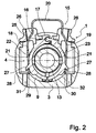
- Fig. 2 on average, the embodiment according to Fig. 1 in the region of the fixing arrangement 15 during the insertion of the insertion shaft 13 of the insertion part 10 with the securing part 16 in an extended position.
- the outer diameter of the insertion shaft 13 is like Fig. 2 . Apparently smaller than the inner diameter of the formed by the retaining wings 22, 23 ring which surrounds the insertion shaft 13 in this stationary Umgreifwolf of the retaining member 17.
- the cover portion 20 is disposed in the extended position of the securing member 16 at a distance from the hinge 25, and the hinge 25 opposite free ends of the retaining wings 22, 23 are due to the biased by the securing arms 18, 19 acting radially inwardly biasing force to each other.
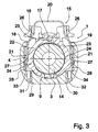
- Fig. 3 shows the arrangement according to Fig. 2 with the end collar 14 formed on the insertion part 10 in a position lying in the region of the fixing arrangement 15 during insertion of the insertion part 10 at the moment in which the retention wing 22, 23 passes through the stem 14 in the region of the smallest diameter caused by the retention sections 24 the retaining wings 22, 23 are furthest apart in an overhanging position.
- the free ends 28 of the locking arms 18, 19 are no longer on the locking surfaces 29, 30, but are arranged in the insertion direction of the securing part 16 aligned blocking surfaces 33, 34 opposite, the radially outside on the locking surfaces 29, 30 opposite sides of Immersion channels 31, 32 are formed so that a displacement of the securing member 16 is further blocked from the extended position in the direction of the center of the receiving space 4.
- Fig. 4 is a longitudinal section of the arrangement according to Fig. 3 , from which it can be clearly seen that when positioning the Stimbundes 14 between the radially inwardly projecting into the receiving space 4 retaining portions 24, the retaining wings 22, 23 are forced into the over-position, so that in this transition phase, despite a seemingly almost outwardly from the outside arrangement the male member 10 in the receiving part 1 by the still protruding and blocked against insertion Securing part 16 is clearly visible that the retaining portions 24 have the headband 14 not yet engaged.
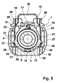
- Fig. 5 make the arrangement according to Fig. 2 to Fig. 4 Immediately after the passage of the Stimbundes 14 by the fixing 15, in which the securing arms 18, 19 are aligned due to corresponding dimensioning of Stirnbundes 14 now aligned with the immersion channels 31, 32.
- the securing part 16 can be transferred from the extended position into an inserted position by exerting a force on the cover section 20 in the direction of the center of the receiving space 4.
- Fig. 6 is a longitudinal section of the arrangement according to Fig. 5 can be clearly seen that now the retaining portions 24 behind the headband 14 and under investment in the insertion of the male 10 back of the retaining portions 24 lying areas of the retaining wings 22, 23 on the end collar 14 thus secure the male member 10 in the receiving part 1, so that after insertion of the security part 16 of the connection process is completed as properly recognizable.
- Fig. 7 shows the arrangement according to Fig. 2 to Fig. 6 with the securing part 16 in the inserted position, in which the securing arms 18, 19 are arranged in the immersion channels 31, 32 and extend to the outside of the securing body 3.
- the securing member 16 engage behind the retaining portions 24 of the retaining wings 22, 23 under radially inwardly directed bias the headband 14, and the male member 10 is fixed in the receiving part 1 against unintentional withdrawal against the insertion direction.
- the actuating structures 26 are to be acted upon by forces which cause the retainer wings 22, 23 to pivot radially outwardly into the lead over position so that the rear grip of the retaining portions 24 is repealed.
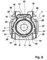
- Fig. 8 shows a relation to the embodiment according to Fig. 1 to Fig. 7 modified embodiment in the arrangement according to Fig. 3 in which the immersion channels 31, 32 are formed with the elimination of the blocking surfaces 33, 34 as radially outwardly open immersion spaces, so that the securing member 16 is already in the extended position in the inserted position can be transferred and further removing the plug 10 by transferring the Retaining wings 22, 23 can be reached in the excess position without the securing member 16 has to be moved from the retracted position to the extended position.
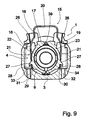
- Fig. 9 represents on average over the embodiment according to Fig. 1 to Fig. 7 in the region of the retaining member 17 modified embodiment, in which the retaining member 17 is integrally formed with a flexible flexible connecting portion 39 which connects the retaining wings 22, 23 pivotally connected to each other in the manner of a film hinge.
- This embodiment is characterized by an advantageous simple structure.
- Fig. 10 represents on average over the embodiment according to Fig. 1 to Fig. 7 and compared to the embodiment according to Fig. 9 in the region of the retaining member 17 further modified embodiment.
- the embodiment according to Fig. 10 is formed on the securing body 3 separating dome 40 which, after a first insertion of the retaining member 17 into the receiving space 4 originally formed between the retaining wings 22, 23 formed thin bridge section 41, so that the retaining wings 22, 23 now not directly, but over the securing part 16 are connected to each other.
Landscapes
- Engineering & Computer Science (AREA)
- General Engineering & Computer Science (AREA)
- Mechanical Engineering (AREA)
- Quick-Acting Or Multi-Walled Pipe Joints (AREA)
- Clamps And Clips (AREA)
- Control Of Motors That Do Not Use Commutators (AREA)
- Financial Or Insurance-Related Operations Such As Payment And Settlement (AREA)
- Mutual Connection Of Rods And Tubes (AREA)
- Paper (AREA)
- Lubrication Of Internal Combustion Engines (AREA)
- Endoscopes (AREA)
Priority Applications (1)
| Application Number | Priority Date | Filing Date | Title |
|---|---|---|---|
| PL07723486T PL2013525T3 (pl) | 2006-04-26 | 2007-03-22 | Połączenie przewodu hydraulicznego |
Applications Claiming Priority (2)
| Application Number | Priority Date | Filing Date | Title |
|---|---|---|---|
| DE102006019257A DE102006019257B4 (de) | 2006-04-26 | 2006-04-26 | Fluidleitungskupplung |
| PCT/EP2007/002529 WO2007124818A1 (de) | 2006-04-26 | 2007-03-22 | Fluidleitungskupplung |
Publications (2)
| Publication Number | Publication Date |
|---|---|
| EP2013525A1 EP2013525A1 (de) | 2009-01-14 |
| EP2013525B1 true EP2013525B1 (de) | 2010-12-08 |
Family
ID=38028179
Family Applications (1)
| Application Number | Title | Priority Date | Filing Date |
|---|---|---|---|
| EP07723486A Active EP2013525B1 (de) | 2006-04-26 | 2007-03-22 | Fluidleitungskupplung |
Country Status (12)
| Country | Link |
|---|---|
| US (1) | US20080315576A1 (pl) |
| EP (1) | EP2013525B1 (pl) |
| JP (1) | JP4926239B2 (pl) |
| KR (1) | KR101001230B1 (pl) |
| CN (1) | CN101400937B (pl) |
| AT (1) | ATE491113T1 (pl) |
| BR (1) | BRPI0710902B1 (pl) |
| DE (2) | DE102006019257B4 (pl) |
| ES (1) | ES2356941T3 (pl) |
| PL (1) | PL2013525T3 (pl) |
| RU (1) | RU2395747C1 (pl) |
| WO (1) | WO2007124818A1 (pl) |
Families Citing this family (29)
| Publication number | Priority date | Publication date | Assignee | Title |
|---|---|---|---|---|
| DE102006047267B4 (de) * | 2006-10-04 | 2010-02-04 | A. Raymond Et Cie | Kupplungsteil für eine Fluidleitungskupplung |
| FR2907877B1 (fr) * | 2006-10-31 | 2012-06-22 | Saint Gobain Pont A Mousson | Jonction tubulaire |
| DE102008013565B4 (de) | 2008-03-11 | 2025-12-04 | A. Kayser Automotive Systems Gmbh | Einsteckkupplung |
| EP2196717B1 (en) * | 2008-12-12 | 2012-08-22 | Dresser Wayne AB | Hose connection |
| FR2945100A1 (fr) * | 2009-04-30 | 2010-11-05 | Hutchinson | Raccord encliquetable entre un conduit de fluide et un embout rigide avec un dispositif temoin de connexion et procede de controle de cette connexion |
| DE102009043088B3 (de) * | 2009-09-25 | 2011-03-31 | A. Raymond Et Cie | Einfügekontrolleinheit zur Kontrolle des Steckzustandes eines Einsteckteiles in einem Aufnahmeteil sowie Anordnung mit einer derartigen Einfügekontrolleinheit und einem Aufnahmeteil |
| DE102009050076B3 (de) * | 2009-10-20 | 2011-04-07 | A. Kayser Automotive Systems Gmbh | Einsteckkupplung |
| US20110154711A1 (en) * | 2009-12-28 | 2011-06-30 | James Kenneth Dickerson | Mounting system for muzzle devices and firearms |
| KR101138037B1 (ko) * | 2010-06-29 | 2012-04-23 | 주식회사 니프코코리아 | 자동차 유체통로용 퀵 커넥터 |
| CN102918316B (zh) * | 2010-09-30 | 2015-03-18 | 住友理工株式会社 | 快速连接器 |
| JP5950416B2 (ja) | 2011-06-16 | 2016-07-13 | 株式会社東郷製作所 | 配管用コネクタ |
| AT512397B1 (de) * | 2012-05-07 | 2013-08-15 | Henn Gmbh & Co Kg | Steckverbindung zum Verbinden von Leitungen für unter Druck gesetzte Flüssigkeiten oder Gase |
| US9732892B2 (en) | 2013-01-09 | 2017-08-15 | Gates Corporation | Quick connect coupling with a self-resetting retention mechanism |
| CN103388716B (zh) * | 2013-07-19 | 2015-08-05 | 武汉海纳川科技有限公司 | 一体化气液流体与电信号复合传送带管线插头 |
| US9551443B2 (en) * | 2014-02-19 | 2017-01-24 | Ford Global Technologies, Llc | Engine fluid line with flexible joint |
| US10422459B2 (en) | 2015-01-14 | 2019-09-24 | Norma U.S. Holding Llc | Conduit connector with a primary and secondary latch |
| AT516151B1 (de) * | 2015-03-03 | 2016-03-15 | Henn Gmbh & Co Kg | Steckverbinderbaugruppe zum Verbinden von Leitungen |
| DE102015106063B4 (de) * | 2015-04-21 | 2022-10-06 | Voss Automotive Gmbh | Steckverbindung für Fluid-Leitungen mit einem Halteteil und einer Sekundärverriegelung |
| US10458583B2 (en) * | 2015-08-31 | 2019-10-29 | A. Raymond Et Cie | Unlocking tool for a quick connector assembly |
| AT516939B1 (de) * | 2015-10-07 | 2016-10-15 | Henn Gmbh & Co Kg | Steckverbinder zum Verbinden von Leitungen für flüssige oder gasförmige Medien |
| US20190111777A1 (en) * | 2016-05-02 | 2019-04-18 | Orau Orhan Otomotiv Kontrol Sistemleri Sanayii Anonim Sirketi | Fuel filling line - fuel tank quick connection |
| AT518865B1 (de) | 2017-02-13 | 2018-02-15 | Henn Gmbh & Co Kg | Steckerbaugruppe zur Verwendung in einem Fahrzeug |
| CN106641533B (zh) * | 2017-02-17 | 2018-08-28 | 香河瑞和通汽车零部件有限公司 | 一种具备二次锁紧机构的汽车管路塑料快插接头 |
| US10816121B2 (en) * | 2017-05-09 | 2020-10-27 | Martinrea International US Inc. | Quick connect coupling with verifier |
| US11009159B2 (en) * | 2017-09-28 | 2021-05-18 | AdelWiggins Group, a Division of Transdigm, Inc. | Visual and tactile latch indicator for a fuel system coupling |
| US11199281B2 (en) | 2018-01-31 | 2021-12-14 | A. Raymond Et Cie. | Dual-latch quick connector |
| DE102018122597A1 (de) * | 2018-09-14 | 2020-03-19 | Norma Germany Gmbh | Vorrichtung zum Verbinden zweier röhrenförmiger Objekte |
| US11898676B2 (en) | 2020-05-13 | 2024-02-13 | Mercury Plastics Llc | Quick-connect fitting |
| US12392431B2 (en) | 2020-10-05 | 2025-08-19 | Oetiker Ny, Inc. | Fluid connector including a connection verification contact |
Citations (1)
| Publication number | Priority date | Publication date | Assignee | Title |
|---|---|---|---|---|
| US20050189764A1 (en) * | 2002-10-18 | 2005-09-01 | Takashi Ono | Connector assembly |
Family Cites Families (14)
| Publication number | Priority date | Publication date | Assignee | Title |
|---|---|---|---|---|
| RU2144157C1 (ru) * | 1996-08-12 | 2000-01-10 | Ларин Вячеслав Иванович | Червячный хомут |
| JP2001355777A (ja) * | 2000-06-12 | 2001-12-26 | Togo Seisakusho Corp | 配管用クランプ及びチェッカー |
| DE10115399C1 (de) * | 2001-03-29 | 2002-06-06 | Raymond A & Cie | Lösbare Steckverbindung mit zusätzlichem Verriegelungselement |
| JP2003004185A (ja) * | 2001-04-20 | 2003-01-08 | Takashi Ono | コネクタ組立体 |
| FR2827364B1 (fr) * | 2001-07-12 | 2007-04-20 | Legris Sa | Connecteur rapide |
| DE50204467D1 (de) * | 2002-05-04 | 2006-02-16 | Ti Automotive Fuldabrueck Gmbh | Rohrkupplung für Rohrleitungen |
| JP4354794B2 (ja) * | 2002-12-18 | 2009-10-28 | 株式会社パイオラックス | チェッカー付きコネクタ |
| US7464970B2 (en) * | 2003-10-22 | 2008-12-16 | Togo Seisakusyo Corporation | Pipe joint |
| DE202004002116U1 (de) * | 2004-02-11 | 2004-06-24 | Faller Jun., Alexander | Prüfbare Verbindung |
| US7390025B2 (en) * | 2004-03-31 | 2008-06-24 | Ti Group Automotive Systems, Llc | Secondary latch/verifier for a quick connector |
| US7021676B2 (en) * | 2004-05-10 | 2006-04-04 | Patrik Westerkull | Connector system |
| JP4663254B2 (ja) * | 2004-05-25 | 2011-04-06 | 三桜工業株式会社 | クイックコネクタ |
| DE102004038912B3 (de) * | 2004-08-11 | 2005-06-02 | A. Raymond & Cie | Kupplung |
| DE102004062887B3 (de) * | 2004-12-27 | 2005-10-13 | A. Raymond & Cie | Kupplung |
-
2006
- 2006-04-26 DE DE102006019257A patent/DE102006019257B4/de not_active Expired - Fee Related
-
2007
- 2007-03-22 RU RU2008146417/06A patent/RU2395747C1/ru active
- 2007-03-22 US US12/279,920 patent/US20080315576A1/en not_active Abandoned
- 2007-03-22 JP JP2009506930A patent/JP4926239B2/ja active Active
- 2007-03-22 WO PCT/EP2007/002529 patent/WO2007124818A1/de not_active Ceased
- 2007-03-22 ES ES07723486T patent/ES2356941T3/es active Active
- 2007-03-22 EP EP07723486A patent/EP2013525B1/de active Active
- 2007-03-22 BR BRPI0710902A patent/BRPI0710902B1/pt active IP Right Grant
- 2007-03-22 AT AT07723486T patent/ATE491113T1/de active
- 2007-03-22 KR KR1020087023954A patent/KR101001230B1/ko active Active
- 2007-03-22 CN CN2007800090985A patent/CN101400937B/zh active Active
- 2007-03-22 DE DE502007005896T patent/DE502007005896D1/de active Active
- 2007-03-22 PL PL07723486T patent/PL2013525T3/pl unknown
Patent Citations (1)
| Publication number | Priority date | Publication date | Assignee | Title |
|---|---|---|---|---|
| US20050189764A1 (en) * | 2002-10-18 | 2005-09-01 | Takashi Ono | Connector assembly |
Also Published As
| Publication number | Publication date |
|---|---|
| RU2008146417A (ru) | 2010-06-10 |
| WO2007124818A1 (de) | 2007-11-08 |
| US20080315576A1 (en) | 2008-12-25 |
| KR101001230B1 (ko) | 2010-12-17 |
| HK1125440A1 (zh) | 2009-08-07 |
| DE102006019257B4 (de) | 2010-08-05 |
| CN101400937A (zh) | 2009-04-01 |
| JP2009534610A (ja) | 2009-09-24 |
| ATE491113T1 (de) | 2010-12-15 |
| RU2395747C1 (ru) | 2010-07-27 |
| CN101400937B (zh) | 2010-08-04 |
| DE102006019257A1 (de) | 2007-10-31 |
| JP4926239B2 (ja) | 2012-05-09 |
| PL2013525T3 (pl) | 2011-05-31 |
| ES2356941T3 (es) | 2011-04-14 |
| DE502007005896D1 (en) | 2011-01-20 |
| EP2013525A1 (de) | 2009-01-14 |
| BRPI0710902A2 (pt) | 2012-01-10 |
| KR20080108506A (ko) | 2008-12-15 |
| BRPI0710902B1 (pt) | 2018-07-17 |
Similar Documents
| Publication | Publication Date | Title |
|---|---|---|
| EP2013525B1 (de) | Fluidleitungskupplung | |
| EP1834124B1 (de) | Kupplung | |
| EP2076705B1 (de) | Kupplungsteil für eine fluidleitungskupplung | |
| EP4127543B1 (de) | Steckverbinder mit vormontagesicherung | |
| DE3873033T2 (de) | Bewegliche verbindung fuer rohrfoermige leitungen. | |
| EP3491281B1 (de) | Anschlussverbinder und anordnung eines halteelements und einer verriegelungseinrichtung dafür | |
| DE202011052283U1 (de) | Steckverbindung mit Sicherungselement und Sicherungselement hierfür | |
| DE202020101638U1 (de) | Steckverbinder mit Vormontagesicherung | |
| EP2165104A1 (de) | Ladeluftschlauch | |
| EP1969280B1 (de) | Steckteil für steckverbinderanordnung | |
| EP1264127A1 (de) | Drehbarer absperrhahn für eine steckkupplung mit abgewinkeltem anschlussstutzen | |
| EP1952050B1 (de) | Schnellküpplung für rohre | |
| EP4405606B1 (de) | Steckverbinder mit vormontagesicherung | |
| DE102022208752A1 (de) | Fluidkupplung, Verfahren zum Herstellen einer Fluidkupplung sowie Fluidkupplungsanordnung | |
| WO2018091478A1 (de) | Kupplungsvorrichtung für medienführende leitungen | |
| EP3153757B1 (de) | Lösbare steckverbindung für rohrleitungen | |
| DE102015104889A1 (de) | Steckverbinder für Medienleitungen mit Sekundärverriegelung | |
| EP4070004B1 (de) | Steckkupplung für fluidleitungen | |
| DE102013103534A1 (de) | "Steckverbindungsteil für einen Leitungsverbinder, insbesondere für eine konfektionierte Medienleitung" | |
| EP3372887B1 (de) | Anschlussstück | |
| EP3901509B1 (de) | Lösbare steckverbindung | |
| EP1746329B1 (de) | Steckfitting | |
| WO2008034509A1 (de) | Kupplungsteil für eine fluidleitungsverbindungsanordnung | |
| EP1746330A2 (de) | Aufnahmeteil einer Fluid-Steckverbindung | |
| DE102010019673A1 (de) | Fluidgehäuse mit einem Leitungsanschluss |
Legal Events
| Date | Code | Title | Description |
|---|---|---|---|
| PUAI | Public reference made under article 153(3) epc to a published international application that has entered the european phase |
Free format text: ORIGINAL CODE: 0009012 |
|
| 17P | Request for examination filed |
Effective date: 20081126 |
|
| AK | Designated contracting states |
Kind code of ref document: A1 Designated state(s): AT BE BG CH CY CZ DE DK EE ES FI FR GB GR HU IE IS IT LI LT LU LV MC MT NL PL PT RO SE SI SK TR |
|
| AX | Request for extension of the european patent |
Extension state: AL BA HR MK RS |
|
| 17Q | First examination report despatched |
Effective date: 20091204 |
|
| GRAP | Despatch of communication of intention to grant a patent |
Free format text: ORIGINAL CODE: EPIDOSNIGR1 |
|
| DAX | Request for extension of the european patent (deleted) | ||
| GRAS | Grant fee paid |
Free format text: ORIGINAL CODE: EPIDOSNIGR3 |
|
| GRAA | (expected) grant |
Free format text: ORIGINAL CODE: 0009210 |
|
| AK | Designated contracting states |
Kind code of ref document: B1 Designated state(s): AT BE BG CH CY CZ DE DK EE ES FI FR GB GR HU IE IS IT LI LT LU LV MC MT NL PL PT RO SE SI SK TR |
|
| REG | Reference to a national code |
Ref country code: GB Ref legal event code: FG4D Free format text: NOT ENGLISH |
|
| REG | Reference to a national code |
Ref country code: CH Ref legal event code: EP |
|
| REG | Reference to a national code |
Ref country code: IE Ref legal event code: FG4D |
|
| REF | Corresponds to: |
Ref document number: 502007005896 Country of ref document: DE Date of ref document: 20110120 Kind code of ref document: P |
|
| REG | Reference to a national code |
Ref country code: NL Ref legal event code: VDEP Effective date: 20101208 |
|
| REG | Reference to a national code |
Ref country code: ES Ref legal event code: FG2A Ref document number: 2356941 Country of ref document: ES Kind code of ref document: T3 Effective date: 20110414 |
|
| PG25 | Lapsed in a contracting state [announced via postgrant information from national office to epo] |
Ref country code: LT Free format text: LAPSE BECAUSE OF FAILURE TO SUBMIT A TRANSLATION OF THE DESCRIPTION OR TO PAY THE FEE WITHIN THE PRESCRIBED TIME-LIMIT Effective date: 20101208 |
|
| LTIE | Lt: invalidation of european patent or patent extension |
Effective date: 20101208 |
|
| PG25 | Lapsed in a contracting state [announced via postgrant information from national office to epo] |
Ref country code: FI Free format text: LAPSE BECAUSE OF FAILURE TO SUBMIT A TRANSLATION OF THE DESCRIPTION OR TO PAY THE FEE WITHIN THE PRESCRIBED TIME-LIMIT Effective date: 20101208 Ref country code: CY Free format text: LAPSE BECAUSE OF FAILURE TO SUBMIT A TRANSLATION OF THE DESCRIPTION OR TO PAY THE FEE WITHIN THE PRESCRIBED TIME-LIMIT Effective date: 20101208 Ref country code: LV Free format text: LAPSE BECAUSE OF FAILURE TO SUBMIT A TRANSLATION OF THE DESCRIPTION OR TO PAY THE FEE WITHIN THE PRESCRIBED TIME-LIMIT Effective date: 20101208 Ref country code: SE Free format text: LAPSE BECAUSE OF FAILURE TO SUBMIT A TRANSLATION OF THE DESCRIPTION OR TO PAY THE FEE WITHIN THE PRESCRIBED TIME-LIMIT Effective date: 20101208 Ref country code: SI Free format text: LAPSE BECAUSE OF FAILURE TO SUBMIT A TRANSLATION OF THE DESCRIPTION OR TO PAY THE FEE WITHIN THE PRESCRIBED TIME-LIMIT Effective date: 20101208 Ref country code: BG Free format text: LAPSE BECAUSE OF FAILURE TO SUBMIT A TRANSLATION OF THE DESCRIPTION OR TO PAY THE FEE WITHIN THE PRESCRIBED TIME-LIMIT Effective date: 20110308 Ref country code: NL Free format text: LAPSE BECAUSE OF FAILURE TO SUBMIT A TRANSLATION OF THE DESCRIPTION OR TO PAY THE FEE WITHIN THE PRESCRIBED TIME-LIMIT Effective date: 20101208 |
|
| REG | Reference to a national code |
Ref country code: PL Ref legal event code: T3 |
|
| REG | Reference to a national code |
Ref country code: IE Ref legal event code: FD4D |
|
| PG25 | Lapsed in a contracting state [announced via postgrant information from national office to epo] |
Ref country code: GR Free format text: LAPSE BECAUSE OF FAILURE TO SUBMIT A TRANSLATION OF THE DESCRIPTION OR TO PAY THE FEE WITHIN THE PRESCRIBED TIME-LIMIT Effective date: 20110309 Ref country code: EE Free format text: LAPSE BECAUSE OF FAILURE TO SUBMIT A TRANSLATION OF THE DESCRIPTION OR TO PAY THE FEE WITHIN THE PRESCRIBED TIME-LIMIT Effective date: 20101208 Ref country code: PT Free format text: LAPSE BECAUSE OF FAILURE TO SUBMIT A TRANSLATION OF THE DESCRIPTION OR TO PAY THE FEE WITHIN THE PRESCRIBED TIME-LIMIT Effective date: 20110408 Ref country code: IE Free format text: LAPSE BECAUSE OF FAILURE TO SUBMIT A TRANSLATION OF THE DESCRIPTION OR TO PAY THE FEE WITHIN THE PRESCRIBED TIME-LIMIT Effective date: 20101208 Ref country code: IS Free format text: LAPSE BECAUSE OF FAILURE TO SUBMIT A TRANSLATION OF THE DESCRIPTION OR TO PAY THE FEE WITHIN THE PRESCRIBED TIME-LIMIT Effective date: 20110408 |
|
| PG25 | Lapsed in a contracting state [announced via postgrant information from national office to epo] |
Ref country code: SK Free format text: LAPSE BECAUSE OF FAILURE TO SUBMIT A TRANSLATION OF THE DESCRIPTION OR TO PAY THE FEE WITHIN THE PRESCRIBED TIME-LIMIT Effective date: 20101208 Ref country code: RO Free format text: LAPSE BECAUSE OF FAILURE TO SUBMIT A TRANSLATION OF THE DESCRIPTION OR TO PAY THE FEE WITHIN THE PRESCRIBED TIME-LIMIT Effective date: 20101208 |
|
| BERE | Be: lapsed |
Owner name: A. RAYMOND ET CIE Effective date: 20110331 |
|
| PLBE | No opposition filed within time limit |
Free format text: ORIGINAL CODE: 0009261 |
|
| STAA | Information on the status of an ep patent application or granted ep patent |
Free format text: STATUS: NO OPPOSITION FILED WITHIN TIME LIMIT |
|
| PG25 | Lapsed in a contracting state [announced via postgrant information from national office to epo] |
Ref country code: DK Free format text: LAPSE BECAUSE OF FAILURE TO SUBMIT A TRANSLATION OF THE DESCRIPTION OR TO PAY THE FEE WITHIN THE PRESCRIBED TIME-LIMIT Effective date: 20101208 Ref country code: MC Free format text: LAPSE BECAUSE OF NON-PAYMENT OF DUE FEES Effective date: 20110331 |
|
| REG | Reference to a national code |
Ref country code: CH Ref legal event code: PL |
|
| 26N | No opposition filed |
Effective date: 20110909 |
|
| PG25 | Lapsed in a contracting state [announced via postgrant information from national office to epo] |
Ref country code: MT Free format text: LAPSE BECAUSE OF FAILURE TO SUBMIT A TRANSLATION OF THE DESCRIPTION OR TO PAY THE FEE WITHIN THE PRESCRIBED TIME-LIMIT Effective date: 20101208 Ref country code: BE Free format text: LAPSE BECAUSE OF NON-PAYMENT OF DUE FEES Effective date: 20110331 |
|
| REG | Reference to a national code |
Ref country code: DE Ref legal event code: R097 Ref document number: 502007005896 Country of ref document: DE Effective date: 20110909 |
|
| PG25 | Lapsed in a contracting state [announced via postgrant information from national office to epo] |
Ref country code: LI Free format text: LAPSE BECAUSE OF NON-PAYMENT OF DUE FEES Effective date: 20110331 Ref country code: CH Free format text: LAPSE BECAUSE OF NON-PAYMENT OF DUE FEES Effective date: 20110331 |
|
| REG | Reference to a national code |
Ref country code: AT Ref legal event code: MM01 Ref document number: 491113 Country of ref document: AT Kind code of ref document: T Effective date: 20120322 |
|
| PG25 | Lapsed in a contracting state [announced via postgrant information from national office to epo] |
Ref country code: LU Free format text: LAPSE BECAUSE OF NON-PAYMENT OF DUE FEES Effective date: 20110322 |
|
| PG25 | Lapsed in a contracting state [announced via postgrant information from national office to epo] |
Ref country code: AT Free format text: LAPSE BECAUSE OF NON-PAYMENT OF DUE FEES Effective date: 20120322 |
|
| PG25 | Lapsed in a contracting state [announced via postgrant information from national office to epo] |
Ref country code: HU Free format text: LAPSE BECAUSE OF FAILURE TO SUBMIT A TRANSLATION OF THE DESCRIPTION OR TO PAY THE FEE WITHIN THE PRESCRIBED TIME-LIMIT Effective date: 20101208 |
|
| REG | Reference to a national code |
Ref country code: DE Ref legal event code: R082 Ref document number: 502007005896 Country of ref document: DE |
|
| REG | Reference to a national code |
Ref country code: FR Ref legal event code: PLFP Year of fee payment: 10 |
|
| REG | Reference to a national code |
Ref country code: FR Ref legal event code: PLFP Year of fee payment: 11 |
|
| REG | Reference to a national code |
Ref country code: FR Ref legal event code: PLFP Year of fee payment: 12 |
|
| P01 | Opt-out of the competence of the unified patent court (upc) registered |
Effective date: 20230524 |
|
| PGFP | Annual fee paid to national office [announced via postgrant information from national office to epo] |
Ref country code: DE Payment date: 20250319 Year of fee payment: 19 |
|
| PGFP | Annual fee paid to national office [announced via postgrant information from national office to epo] |
Ref country code: PL Payment date: 20250313 Year of fee payment: 19 Ref country code: FR Payment date: 20250325 Year of fee payment: 19 Ref country code: CZ Payment date: 20250317 Year of fee payment: 19 |
|
| PGFP | Annual fee paid to national office [announced via postgrant information from national office to epo] |
Ref country code: IT Payment date: 20250325 Year of fee payment: 19 Ref country code: GB Payment date: 20250321 Year of fee payment: 19 |
|
| PGFP | Annual fee paid to national office [announced via postgrant information from national office to epo] |
Ref country code: TR Payment date: 20250317 Year of fee payment: 19 |
|
| PGFP | Annual fee paid to national office [announced via postgrant information from national office to epo] |
Ref country code: ES Payment date: 20250425 Year of fee payment: 19 |