EP3372887B1 - Anschlussstück - Google Patents
Anschlussstück Download PDFInfo
- Publication number
- EP3372887B1 EP3372887B1 EP18160764.9A EP18160764A EP3372887B1 EP 3372887 B1 EP3372887 B1 EP 3372887B1 EP 18160764 A EP18160764 A EP 18160764A EP 3372887 B1 EP3372887 B1 EP 3372887B1
- Authority
- EP
- European Patent Office
- Prior art keywords
- receptacle
- adapter
- insert channel
- insert
- annular groove
- Prior art date
- Legal status (The legal status is an assumption and is not a legal conclusion. Google has not performed a legal analysis and makes no representation as to the accuracy of the status listed.)
- Active
Links
Images




Classifications
-
- F—MECHANICAL ENGINEERING; LIGHTING; HEATING; WEAPONS; BLASTING
- F16—ENGINEERING ELEMENTS AND UNITS; GENERAL MEASURES FOR PRODUCING AND MAINTAINING EFFECTIVE FUNCTIONING OF MACHINES OR INSTALLATIONS; THERMAL INSULATION IN GENERAL
- F16L—PIPES; JOINTS OR FITTINGS FOR PIPES; SUPPORTS FOR PIPES, CABLES OR PROTECTIVE TUBING; MEANS FOR THERMAL INSULATION IN GENERAL
- F16L55/00—Devices or appurtenances for use in, or in connection with, pipes or pipe systems
- F16L55/10—Means for stopping flow in pipes or hoses
- F16L55/1026—Fire protection devices
-
- F—MECHANICAL ENGINEERING; LIGHTING; HEATING; WEAPONS; BLASTING
- F16—ENGINEERING ELEMENTS AND UNITS; GENERAL MEASURES FOR PRODUCING AND MAINTAINING EFFECTIVE FUNCTIONING OF MACHINES OR INSTALLATIONS; THERMAL INSULATION IN GENERAL
- F16L—PIPES; JOINTS OR FITTINGS FOR PIPES; SUPPORTS FOR PIPES, CABLES OR PROTECTIVE TUBING; MEANS FOR THERMAL INSULATION IN GENERAL
- F16L5/00—Devices for use where pipes, cables or protective tubing pass through walls or partitions
- F16L5/02—Sealing
- F16L5/04—Sealing to form a firebreak device
-
- F—MECHANICAL ENGINEERING; LIGHTING; HEATING; WEAPONS; BLASTING
- F16—ENGINEERING ELEMENTS AND UNITS; GENERAL MEASURES FOR PRODUCING AND MAINTAINING EFFECTIVE FUNCTIONING OF MACHINES OR INSTALLATIONS; THERMAL INSULATION IN GENERAL
- F16L—PIPES; JOINTS OR FITTINGS FOR PIPES; SUPPORTS FOR PIPES, CABLES OR PROTECTIVE TUBING; MEANS FOR THERMAL INSULATION IN GENERAL
- F16L59/00—Thermal insulation in general
- F16L59/14—Arrangements for the insulation of pipes or pipe systems
- F16L59/145—Arrangements for the insulation of pipes or pipe systems providing fire-resistance
-
- A—HUMAN NECESSITIES
- A62—LIFE-SAVING; FIRE-FIGHTING
- A62C—FIRE-FIGHTING
- A62C2/00—Fire prevention or containment
- A62C2/06—Physical fire-barriers
- A62C2/065—Physical fire-barriers having as the main closure device materials, whose characteristics undergo an irreversible change under high temperatures, e.g. intumescent
Definitions
- connection piece comprising a cast body with an integrally formed plug-in socket which has an insertion opening and an insertion channel extending from the insertion opening into the plug-in socket, which is designed to receive a spigot end of a plastic pipe, for example from the JP 2010-190034 known.
- connection pieces of this type there is the problem of designing them to be fire-proof.
- document EP 1512434A1 discloses a connection piece as a fire protection element for the implementation of pipelines.
- An intumescent material is a material that inflates many times its volume when heat is introduced and is able to close the insertion channel due to its inflation, in particular by destroying or deforming the spigot end of the plastic pipe.
- the receptacle extends at least in sections in the circumferential direction around the insertion channel, so that the intumescent material can initially be attached partially encompassing the tip end.
- the receptacle extends in a closed manner around the insertion channel.
- intumescent material is arranged in the receptacle in the form of at least one curved segment body.
- a curved segment body is to be understood here as a body which extends over a curved segment around the insertion channel, wherein the curved segment can have a wide variety of arc lengths.
- the arch segment body in the receptacle has segment ends arranged at a distance from one another so that the arch segment body can be deformed for insertion into the receptacle and then in the receptacle with the formation of an increasing distance between can widen the segment ends.
- a particularly favorable solution provides that the at least one curved segment body is designed in the form of an annular body open on one side.
- a plug-in socket circumferential wall surrounding the receptacle radially on the outside has at least one opening.
- the opening is designed as a slot extending parallel to the central axis of the insertion channel.
- the invention provides that the socket has an annular groove surrounding the insertion channel on a side of the receptacle opposite the insertion opening, in which a seal is arranged which creates a seal between the cast body and the spigot end of the Plastic pipe causes.
- Such a seal can be designed in the most varied of ways.
- the seal has an annular body and, proceeding from this, has elastic sealing lips projecting into the insertion channel.
- sealing lips designed in this way, there is the possibility of deforming the sealing lips when inserting the spigot end and thus achieving at least one seal that is as linear as possible around the spigot end and also generating a sufficiently high radial pressure within the seal.
- the solution according to the invention provides that the annular groove, starting from the insertion channel, has a smaller extent in the radial direction than the receptacle.
- the annular groove has a smaller radial depth in an area facing the receptacle, starting from the insertion channel, than in an area facing away from the receptacle.
- This design of the annular groove allows the seal to be advantageously set in the annular groove.
- a base area of the annular groove is designed to widen conically away from the receptacle in the direction parallel to the central axis of the entry channel.
- a transition region is provided between the annular groove and the receptacle, which is located radially outside the insertion channel and through which an extension of the seal extends into the receptacle.
- This solution has the advantage that it allows the seal to be fixed in a simple manner against displacement when the spigot end of the plastic pipe is inserted into the annular groove.
- the extension has a flange body that widens radially in the receptacle, so that the extension in the receptacle thereby enables the seal to be secured against displacement in the direction parallel to the central axis of the insertion channel when the spigot end is inserted.
- the flange body is preferably designed in such a way that it rests against a side wall of the socket housing that extends transversely to the insertion channel and delimits the receptacle in order to be able to fix the seal in the socket in a simple manner.
- connection piece A wide variety of possibilities are conceivable with regard to the arrangement of the connection piece.
- this connection piece could be formed by one end of a cast pipe.
- connection piece is part of a fitting, whereby a fitting is to be understood as a part that has shapes that differ from a simple pipe, such as a pipe bend or an end of a fitting, etc.
- connection piece according to the invention that this is part of a fitting forming a branch.
- connection piece is designed as a pipe connection piece of the shaped piece.
- FIG. 1 An in Fig. 1
- the illustrated embodiment of a fire protection connection piece 10 according to the invention is part of a molded piece 12 made of cast iron, which is designed, for example, as a branch.
- the molded piece 12 comprises a passage piece 14 made of cast iron, from which a pipe connection piece 16 which includes the fire protection connection piece 10 branches off, which in turn is integrally formed on the passage piece 14 and which has a socket 18, the branching pipe connection piece 16 and the socket 18 being part of a whole are denoted by 20 cast body, which in the illustrated embodiment in particular also includes the passage piece 14.
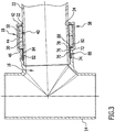
- the socket 18 has an insertion opening 22 facing away from the through piece 14, from which an insertion channel 24 extending coaxially to a central axis 26 extends into the socket 18, as shown in FIG Fig. 2 shown, where, as in Fig. 3 shown, in the insertion channel 24, starting from the insertion opening 22, a pointed end 30 of a plastic pipe 32 to be connected to the pipe connection piece 16 can be inserted.
- the socket 18 comprises a socket housing 38 and a receptacle 40 arranged therein, which is open towards the insertion channel 24 and, starting from the insertion channel 24, extends in the radial direction to the central axis 26 of the insertion channel 24.
- the receptacle 40 is delimited in particular by a side wall 42 extending radially to the central axis starting from the insertion opening 22, a plug-in socket circumferential wall 44 which extends in particular cylindrical to the central axis 26 and which extends from the side wall 42 in the direction of the through piece 14, and one of the insertion opening 22 facing away from the side wall 46 which, starting from the socket peripheral wall 44, extends in the direction of the insertion channel 24 and transversely to this.
- the side wall 42, the socket peripheral wall 44 and the side wall 46 are each parts of the socket housing designated as a whole as 38.
- the side wall 42 and the side wall 46 preferably extend in the direction of the central axis 26 at a distance from one another and in directions running transversely to the central axis 26, in particular directions running parallel to the central axis 26.
- an intumescent material designated as a whole by 50 is inserted into the receptacle 40, which is arranged between the side walls 42 and 44 and rests against the socket peripheral wall 44.
- the intumescent material 40 preferably extends, starting from the socket peripheral wall 44, radially to the central axis 26 up to the insertion channel 24.
- the intumescent material 50 is arranged in the form of at least one arcuate segment body 52, which in particular is not closed in a ring, but has two mutually facing ends 54 and 56, which are spaced apart when the arcuate segment body 52 is placed on the socket peripheral wall 44 enable the arc segment body 52 to be deformed in a spiral-like manner in order to insert it through the insertion opening 22 into the receptacle 40.
- two successive arc segment bodies 52a, 52b are provided in the direction parallel to the central axis 26, which bear against one another in the direction parallel to the central axis 26, whereby for example the arc segment body 52a with its side facing away from the arc segment body 52b is in contact with the side wall 46 and the arc segment body 52b with it its side facing away from the arcuate segment body 52a rests against the side wall 42.
- Each of the curved segment bodies 52 is dimensioned such that, when inserted into the receptacle 40, it rests on the one hand on the socket circumferential wall 44 and on the other hand has an inner surface 58 opposite the socket circumferential wall 44, which either delimits the insertion channel 24 or is at a slight radial distance from the central axis 26 outside the Insertion channel 24 runs.
- the cast iron of the cast body 20 conducts the heat to the socket 18 so that the intumescent material 50 is heated via the side walls 42 and 46 and the socket circumferential wall 44, which, as in FIG Fig. 5 shown, inflates in such a way that it closes the plug-in channel 24, with the inflation of the intumescent material 50 causing a deformation of the through the occurring temperature also softened tip end 30 of the plastic tube 32 takes place, so that this is either closed or destroyed due to its softening and thus the inflated intumescent material 50 closes the entire insertion channel 24 in the area of the socket 18.
- the socket peripheral wall 44 is also, as in the Fig. 1 , 2 , 3 and 4th , shown by way of example, provided with mutually opposite openings 62 and 64, which are designed, for example, as slots, which extend in the socket circumferential wall 44 parallel to the central axis 26 between the side walls 42 and 44.
- the openings 62, 64 have the advantage that they can be used to check in a simple manner whether the intumescent material has been installed correctly.
- annular groove 70 surrounding the insertion channel 24 is provided, in which a seal designated as a whole with 80 is inserted, which in turn forms a seal between the cast body 20 in the area the socket 18 and the spigot 30 of the plastic pipe 32 causes.
- the seal 80 preferably comprises an annular body 82 seated in the annular groove 70 and elastic annular sealing lips 84 protruding from the annular body 82 radially in the direction of the insertion channel radially to the central axis 26 in the direction of the insertion channel 24 and in particular protruding into the insertion channel 24 without an inserted spigot end ( Fig. 2 ), which, as in Fig. 3 shown, in which the spigot end 30 inserted into the socket 18 is deformed and, in particular, sealing the spigot end 30 with the latter in a linear manner.
- the annular groove 70 in the plug-in sleeve 80 is designed in such a way that, starting from the insertion channel 24 in the radial direction to the central axis 26, it has a smaller extent than the exception 40 for the intumescent material 50.
- the annular groove 70 is designed such that, starting from the insertion channel 24, its radial depth in an area 72 facing the receptacle 40 is less than in an area 74 facing away from the receptacle 40.
- this can be achieved in that the groove 70 has a base area 76, which, based on the central axis 26 of the insertion channel 24, extends from the receptacle 40 in the direction of the passage piece 14 and widens conically.
- the annular body 82 of the seal 80 is also provided with a conically widening outer surface 86 which, when the annular body 82 is seated in the annular groove 70, rests against the base surface 76 of the annular groove 70.
- the annular groove 70 merges with a transition region 78 into the receptacle 40, so that a contact with the annular body 82 of the Seal 80 molded, for example ring-shaped, extension 88 of the seal can extend into the receptacle 40 and form a flange body 92 that widens radially in the receptacle 40 and rests on a support surface 94 of the side wall 46 facing the receptacle 40 and thus between the side wall 46 and the arc segment body 52a arranged following this.
- the radially extending annular flange body 92 located in the receptacle 40 thus creates the possibility of fixing the seal 80, in particular the annular body 82 of the seal 80, in the annular groove 70 against displacement in the direction of the passage piece 14.
- the conically widening course of the base surface 76 of the annular groove 70 in the direction away from the receptacle 40 and the corresponding conical course of the outer surface 86 of the annular body 82 of the seal when the spigot end 30 of the plastic tube 32 is inserted secures the spigot end 30 against being pulled out the insertion channel 24, in particular in view of the pressure occurring between the base surface 76 of the annular groove 70 and the spigot end 30 of the plastic tube 32 due to the annular elastic sealing lips 84.
Landscapes
- Engineering & Computer Science (AREA)
- General Engineering & Computer Science (AREA)
- Mechanical Engineering (AREA)
- Quick-Acting Or Multi-Walled Pipe Joints (AREA)
Description
- Die Erfindung betrifft ein Anschlussstück, umfassend einen Gusskörper mit einer angeformten Steckmuffe, die eine Einstecköffnung und einen sich von der Einstecköffnung in die Steckmuffe hineinerstreckenden Einsteckkanal aufweist, welcher zur Aufnahme eines Spitzendes eines Kunststoffrohrs ausgebildet ist, wie beispielsweise aus der
JP 2010-190034 - Bei derartigen Anschlussstücken besteht das Problem, diese brandsicher auszubilden. Dokument
EP 1512434A1 offenbart ein Anschlussstück als Brandschutzelement, zur Durchführung von Rohrleitungen. Z - Diese Aufgabe wird bei einem Anschlussstück der eingangs beschriebenen Art erfindungsgemäß durch die Merkmale des Anspruchs 1 gelöst.
- Der Vorteil dieser Lösung ist darin zu sehen, dass damit in einfacher Weise die Anordnung eines Intumeszenzmaterials in das Anschlussstück integriert werden kann.
- Ein Intumeszenzmaterial ist dabei ein Material, das sich bei einem Wärmeeintrag um ein Vielfaches seines Volumens aufbläht und in der Lage ist, den Einsteckkanal aufgrund seiner Aufblähung zu verschließen, insbesondere unter Zerstörung oder Deformation des Spitzendes des Kunststoffrohrs.
- Besonders günstig ist es dabei, wenn bei einem derartigen Anschlussstück die Aufnahme sich zumindest abschnittsweise in Umfangsrichtung um den Einsteckkanal herum erstreckt, so dass damit eine das Spitzende zunächst teilweise umfassende Anbringung des Intumeszenzmaterials möglich ist. Insbesondere ist vorgesehen, dass sich die Aufnahme um den Einsteckkanal herum geschlossen umlaufend erstreckt.
- Hinsichtlich der Anordnung des Intumeszenzmaterials in der Aufnahme sind die unterschiedlichsten Möglichkeiten denkbar.
- Eine Möglichkeit wäre, das Intumeszenzmaterial als pastöses Material in die Aufnahme einzubringen.
- Eine besonders vorteilhafte Lösung sieht vor, dass in der Aufnahme das Intumeszenzmaterial in Form von mindestens einem Bogensegmentkörper angeordnet ist.
- Unter einem Bogensegmentkörper ist dabei ein Körper zu verstehen, der sich über ein Bogensegment um den Einsteckkanal herum erstreckt, wobei das Bogensegment unterschiedlichste Bogenlängen aufweisen kann.
- Zum Einsetzen des Bogensegmentkörpers hat es sich als günstig erwiesen, wenn der Bogensegmentkörper in der Aufnahme im Abstand von einander angeordnete Segmentenden aufweist, so dass der Bogensegmentkörper zum Einsetzen in die Aufnahme deformiert werden kann und sich dann in der Aufnahme unter Ausbildung eines sich vergrößernden Abstandes zwischen den Segmentenden aufweiten kann.
- Eine besonders günstige Lösung sieht vor, dass der mindestens eine Bogensegmentkörper in Form eines einseitig offenen Ringkörpers ausgebildet ist.
- Darüber hinaus ist vorzugsweise vorgesehen, dass eine die Aufnahme radial außen liegend umschließende Steckmuffenumfangswand mindestens einen Durchbruch aufweist.
- Ein derartiger Durchbruch hat den Vorteil, dass damit eine einfache Sichtkontrolle zur Überführung der Anwesenheit des Intumeszenzmaterials möglich ist. Zudem erreicht die außerhalb der Steckmuffe vorhandene Wärme über den Durchbruch direkt die Intumeszenzmasse und das Auslösen der Intumeszenzmasse wird dadurch beschleunigt.
- Besonders vorteilhaft ist es, wenn der Durchbruch als ein sich parallel zur Mittelachse des Einsteckkanals erstreckender Schlitz ausgebildet ist.
- Um eine zuverlässige Abdichtung des Spitzendes mit der Steckmuffe zu erreichen ist erfindungsgemäß vorgesehen, dass die Steckmuffe auf einer der Einstecköffnung gegenüberliegenden Seite der Aufnahme eine den Einstecckanal umschließende Ringnut aufweist, in welcher eine Dichtung angeordnet ist, welche eine Abdichtung zwischen dem Gusskörper und dem Spitzende des Kunststoffrohrs bewirkt.
- Eine derartige Dichtung kann in unterschiedlichster Art und Weise ausgebildet sein.
- Insbesondere ist dabei vorgesehen, dass die Dichtung einen Ringkörper und ausgehend von diesem in den Einsteckkanal hineinragende elastische Dichtlippen aufweist.
- Bei derart ausgebildeten Dichtlippen besteht die Möglichkeit, beim Einstecken des Spitzendes die Dichtlippen zu deformieren und somit mindestens eine um das Spitzende umlaufende möglichst linienförmige Abdichtung zu erreichen und außerdem eine ausreichend hohe radiale Pressung innerhalb der Dichtung zu erzeugen.
- Hinsichtlich der Ausbildung der Ringnut sind ebenfalls die unterschiedlichsten Varianten denkbar.
- So sieht die erfindungsgemäße Lösung vor, dass die Ringnut ausgehend von dem Einsteckkanal in radialer Richtung eine geringere Ausdehnung aufweist als die Aufnahme.
- Ferner ist vorzugsweise vorgesehen, dass die Ringnut in einem der Aufnahme zugewandten Bereich ausgehend von dem Einsteckkanal eine geringere radiale Tiefe aufweist, als in einem der Aufnahme abgewandten Bereich.
- Diese Ausbildung der Ringnut erlaubt es, die Dichtung in der Ringnut vorteilhaft festzulegen.
- Insbesondere ist dabei vorgesehen, dass eine Grundfläche der Ringnut sich in Richtung parallel zu der Mittelachse des Einstiegkanals von der Aufnahme weg konisch erweitert ausgebildet ist.
- Damit besteht die Möglichkeit, mittels der Dichtung gleichzeitig das Spitzende gegen ein herausgleiten aus dem Einsteckkanal zu sichern.
- Ferner ist vorzugsweise vorgesehen, dass zwischen der Ringnut und der Aufnahme ein radial außerhalb des Einsteckkanals liegender Übergangsbereich vorgesehen ist, durch welchen sich ein Fortsatz der Dichtung in die Aufnahme hinein erstreckt.
- Diese Lösung hat den Vorteil, dass sich dadurch die Dichtung in einfacher Weise gegen ein Verschieben beim Einstecken des Spitzendes des Kunststoffrohrs in der Ringnut festlegen lässt.
- Besonders günstig ist es, wenn der Fortsatz einen in der Aufnahme sich radial erweiternden Flanschkörper aufweist, so dass dadurch der Fortsatz in der Aufnahme eine Sicherung der Dichtung gegen ein Verschieben in Richtung parallel zur Mittelachse des Einsteckkanals beim Einstecken des Spitzendes ermöglicht.
- Vorzugsweise ist der Flanschkörper so ausgebildet, dass er an einer quer zum Einsteckkanal verlaufenden, die Aufnahme begrenzenden Seitenwand des Steckmuffengehäuses anliegt, um somit die Dichtung in einfacher Weise in der Steckmuffe festlegen zu können.
- Hinsichtlich der Anordnung des Anschlussstücks sind die unterschiedlichsten Möglichkeiten denkbar.
- Prinzipiell könnte dieses Anschlussstück durch ein Ende eines Gussrohrs gebildet werden.
- Eine besonders bevorzugte Lösung sieht vor, dass das Anschlussstück Teil eines Formstücks ist, wobei unter einem Formstück ein Teil zu verstehen ist, das von einem einfachen Rohr abweichende Formen aufweist, wie beispielsweise ein Rohrbogen, oder ein Ende einer Armatur etc.
- Insbesondere ist bei dem erfindungsgemäßen Anschlussstück vorgesehen, dass dieses ein Teil eines einen Abzweig bildenden Formstücks ist.
- Eine besonders vorteilhafte Lösung sieht vor, dass das Anschlussstück als ein Rohranschlussstück des Formstücks ausgebildet ist.
- Weitere Merkmale und Vorteile der Erfindung sind Gegenstand der nachfolgenden Beschreibung sowie der zeichnerischen Darstellung einiger Ausführungsbeispiele.
- In der Zeichnung zeigen:
- Fig. 1
- eine perspektivische Darstellung eines Formstücks mit einem erfindungsgemäßen Anschlussstück;
- Fig. 2
- einen Schnitt längs Linie 2-2 in
Fig. 1 ; - Fig. 3
- ein Schnitt ähnlich
Fig. 2 mit einem in eine Steckmuffe des Anschlussstücks eingesteckten Spitzende eines Kunststoffrohrs; - Fig. 4
- einen Schnitt längs Linie 4-4 in
Fig. 2 ; - Fig. 5
- einen Schnitt entsprechend
Fig. 4 bei aufgeblähtem Intumeszenzmaterial und - Fig. 6
- einen Schnitt längs Linie 6-6 in
Fig. 2 . - Ein in
Fig. 1 dargestelltes Ausführungsbeispiel eines erfindungsgemäßen Brandschutzanschlussstücks 10 ist ein Teil eines Formstücks 12 aus Gusseisen, welches beispielsweise als Abzweig ausgebildet ist. - Das Formstück 12 umfasst ein Durchgangsstück 14 aus Gusseisen, von welchem ein das Brandschutzanschlussstück 10 umfassendes Rohranschlussstück 16 abzweigt, das seinerseits einstückig an das Durchgangsstück 14 angeformt ist und das eine Steckmuffe 18 aufweist, wobei das abzweigende Rohranschlussstück 16 und die Steckmuffe 18 Teil eines als Ganzes mit 20 bezeichneten Gusskörpers sind, der im dargestellten Ausführungsbeispiel insbesondere auch das Durchgangsstück 14 umfasst.
- Die Steckmuffe 18 weist eine dem Durchgangsstück 14 abgewandte Einstecköffnung 22 auf, von welcher ausgehend sich ein koaxial zu einer Mittelachse 26 verlaufender Einsteckkanal 24 in die Steckmuffe 18 hineinerstreckt, wie in
Fig. 2 dargestellt, wobei, wie inFig. 3 dargestellt, in den Einsteckkanal 24 ausgehend von der Einstecköffnung 22 ein Spitzende 30 eines an das Rohranschlussstück 16 anzuschließenden Kunststoffrohrs 32 einsteckbar ist. - Wie insbesondere in
Fig. 2 dargestellt, umfasst die Steckmuffe 18 ein Steckmuffengehäuse 38 und eine in diesem angeordnete Aufnahme 40, welche zum Einsteckkanal 24 hin offen ist und sich ausgehend von dem Einsteckkanal 24 in radialer Richtung zu der Mittelachse 26 des Einsteckkanals 24 erstreckt. - Die Aufnahme 40 ist insbesondere begrenzt durch eine sich ausgehend von der Einstecköffnung 22 radial zur Mittelachse erstreckende Seitenwand 42, eine insbesondere zylindrisch zur Mittelachse 26 verlaufende Steckmuffenumfangswand 44, die sich von der Seitenwand 42 ausgehend in Richtung des Durchgangsstücks 14 erstreckt, und eine der Einstecköffnung 22 abgewandt angeordnete Seitenwand 46, die sich ausgehend von der Steckmuffenumfangswand 44 in Richtung des Einsteckkanals 24 und quer zu diesem erstreckt.
- Dabei sind die Seitenwand 42, die Steckmuffenumfangswand 44 und die Seitenwand 46 jeweils Teile des als Ganzes mit 38 bezeichneten Steckmuffengehäuses.
- Ferner erstrecken sich vorzugsweise die Seitenwand 42 und die Seitenwand 46 in Richtung der Mittelachse 26 im Abstand voneinander und in quer zur Mittelachse 26 verlaufenden Richtungen, insbesondere senkrecht zur Mittelachse 26 parallel verlaufenden Richtungen.
- In die Aufnahme 40 ist ein als Ganzes mit 50 bezeichnetes Intumeszenzmaterial eingesetzt, welches zwischen den Seitenwänden 42 und 44 angeordnet ist und an der Steckmuffenumfangswand 44 anliegt. Vorzugsweise erstreckt sich dabei das Intumeszenzmaterial 40 ausgehend von der Steckmuffenumfangswand 44 radial zur Mittelachse 26 hin bis zum Einsteckkanal 24.
- Wie in den
Fig. 1 ,2 ,3 und4 dargestellt, ist das Intumeszenzmaterial 50 in Form von mindestens einem Bogensegmentkörper 52 angeordnet, der insbesondere nicht ringförmig geschlossen ist, sondern zwei einander zugewandte Enden 54 und 56 aufweist, die beim Anlegen des Bogensegmentkörpers 52 an der Steckmuffenumfangswand 44 im Abstand voneinander angeordnet sind, es jedoch ermöglichen, den Bogensegmentkörper 52 spiralähnlich zu deformieren, um diesen durch die Einstecköffnung 22 in die Aufnahme 40 einzusetzen. - Beim dargestellten Ausführungsbeispiel sind in Richtung parallel zur Mittelachse 26 zwei aufeinanderfolgende Bogensegmentkörper 52a, 52b vorgesehen, die in Richtung parallel zur Mittelachse 26 aneinander anliegen, wobei beispielsweise der Bogensegmentkörper 52a mit seiner dem Bogensegmentkörper 52b abgewandten Seite an der Seitenwand 46 anliegt und der Bogensegmentkörper 52b mit seiner dem Bogensegmentkörper 52a abgewandten Seite an der Seitenwand 42 anliegt.
- Jeder der Bogensegmentkörper 52 ist so dimensioniert, dass dieser im in die Aufnahme 40 eingesetzten Zustand einerseits an der Steckmuffenumfangswand 44 anliegt und andererseits der Steckmuffenumfangswand 44 gegenüberliegend eine Innenfläche 58 aufweist, die entweder den Einsteckkanal 24 begrenzt oder in geringfügigem radialem Abstand zur Mittelachse 26 außerhalb des Einsteckkanals 24 verläuft.
- Beim Auftreten eines Brandes nahe des Formstücks 12 leitet das Gusseisen des Gusskörpers 20 die Wärme zu der Steckmuffe 18 so dass über die Seitenwände 42 und 46 und die Steckmuffenumfangswand 44 eine Aufheizung des Intumeszenzmaterials 50 erfolgt, das, wie in
Fig. 5 dargestellt, sich derart aufbläht, dass dieses den Einsteckkanal 24 verschließt, wobei durch das Aufblähen des Intumeszenzmaterials 50 eine Deformation des durch die auftretende Temperatur ebenfalls erweichten Spitzendes 30 des Kunststoffrohrs 32 erfolgt, so dass dieses entweder verschlossen wird oder aufgrund seiner Erweichung zerstört wird und somit das aufgeblähte Intumeszenzmaterial 50 den gesamten Einsteckkanal 24 im Bereich der Steckmuffe 18 verschließt. - Die Steckmuffenumfangswand 44 ist ferner, wie in den
Fig. 1 ,2 ,3 und4 , beispielhaft dargestellt, mit einander gegenüberliegenden Durchbrüchen 62 und 64 versehen, die beispielsweise als Schlitze ausgebildet sind, welche sich in der Steckmuffenumfangswand 44 parallel zur Mittelachse 26 zwischen den Seitenwänden 42 und 44 erstrecken. - Die Durchbrüche 62, 64 haben den Vorteil, dass sich damit in einfacher Weise überprüfen lässt, ob das Intumeszenzmaterial korrekt eingebaut ist.
- Zur Abdichtung des Spitzendes 30 des Kunststoffrohrs 32 ist auf einer der Einstecköffnung 22 gegenüberliegenden Seite der Aufnahme 40 eine den Einsteckkanal 24 umschließende Ringnut 70 vorgesehen, in welche eine als Ganzes mit 80 bezeichnete Dichtung eingesetzt ist, die ihrerseits eine Abdichtung zwischen dem Gusskörper 20 im Bereich der Steckmuffe 18 und dem Spitzende 30 des Kunststoffrohrs 32 bewirkt.
- Dabei umfasst die Dichtung 80 vorzugsweise einen in der Ringnut 70 sitzenden Ringkörper 82 und von dem Ringkörper 82 radial in Richtung des Einstecckanals radial zur Mittelachse 26 in Richtung des Einsteckkanals 24 vorspringende und insbesondere ohne eingestecktes Spitzende in den Einsteckkanal 24 hineinragende elastische Ringdichtlippen 84 (
Fig. 2 ), die, wie inFig. 3 dargestellt, bei dem in die Steckmuffe 18 eingesteckten Spitzende 30 deformiert werden und insbesondere linienförmig das Spitzende 30 umschließend mit diesem abdichten. - Erfindungsgemäß ist die Ringnut 70 in der Steckmuffe 80 so ausgebildet, dass sie ausgehend von dem Einsteckkanal 24 in radialer Richtung zur Mittelachse 26 eine geringere Ausdehnung aufweist, als die Ausnahme 40 für das Intumeszenzmaterial 50.
- Ferner ist die Ringnut 70 so ausgebildet, dass ausgehend von dem Einstecckanal 24 deren radiale Tiefe in einem der Aufnahme 40 zugewandten Bereich 72 geringer ist als in einem der Aufnahme 40 abgewandten Bereich 74. Insbesondere lässt sich dies dadurch erreichen, dass die Nut 70 eine Grundfläche 76 aufweist, die bezogen auf die Mittelachse 26 des Einsteckkanals 24 von der Aufnahme 40 ausgehend in Richtung des Durchgangsstücks 14 sich konisch erweiternd verläuft.
- Entsprechend dem Verlauf der Grundfläche 76 der Ringnut ist der Ringkörper 82 der Dichtung 80 ebenfalls mit einer sich konisch erweiternden Außenfläche 86 versehen, die bei in der Ringnut 70 sitzendem Ringkörper 82 an der Grundfläche 76 der Ringnut 70 anliegt.
- Um zu verhindern, dass die Dichtung 80 in der Ringnut 70 beim Einschieben des Spitzendes 30 des Kunststoffrohrs 32 in Richtung des Durchgangsstücks 14 verschoben wird, geht die Ringnut 70 mit einem Übergangsbereich 78 in die Aufnahme 40 über, so dass ein an den Ringkörper 82 der Dichtung 80 angeformter, beispielsweise ringförmiger, Fortsatz 88 der Dichtung sich in die Aufnahme 40 hinein erstrecken kann und einen sich in der Aufnahme 40 radial erweiternden Flanschkörper 92 bildet, der an einer der Aufnahme 40 zugewandten Stützfläche 94 der Seitenwand 46 anliegt und somit zwischen der Seitenwand 46 und dem im Anschluss an diese angeordneten Bogensegmentkörper 52a liegt.
- Der in der Aufnahme 40 liegende, sich radial erstreckende ringförmige Flanschkörper 92 schafft somit die Möglichkeit, die Dichtung 80, insbesondere den Ringkörper 82 der Dichtung 80, in der Ringnut 70 gegen eine Verschiebung in Richtung des Durchgangsstücks 14 festzulegen.
- Darüber hinaus bewirkt der in Richtung von der Aufnahme 40 weg sich konisch erweiternde Verlauf der Grundfläche 76 der Ringnut 70 und der entsprechende konische Verlauf der Außenfläche 86 des Ringkörpers 82 der Dichtung bei eingestecktem Spitzende 30 des Kunststoffrohrs 32 eine Sicherung des Spitzendes 30 gegen ein Herausziehen aus dem Einsteckkanal 24, insbesondere angesichts der durch die ringförmigen elastischen Dichtlippen 84 auftretenden Pressung zwischen der Grundfläche 76 der Ringnut 70 und dem Spitzende 30 des Kunststoffrohrs 32.
Claims (13)
- Anschlussstück, umfassend einen Gusskörper (20), mit einer angeformten Steckmuffe (18), die eine Einstecköffnung (22) und einen sich von der Einstecköffnung (22) in die Steckmuffe (18) hineinerstreckenden Einsteckkanal (24) aufweist, welcher zur Aufnahme eines Spitzendes (30) eines Kunststoffrohrs (32) ausgebildet ist, wobei zur Ausbildung des Anschlussstücks als Brandschutzanschlussstück die Steckmuffe (18) einer ein Steckmuffengehäuse (38) mit radial außerhalb des Einsteckkanals (24) angeordneten und zum Einsteckkanal (24) hin offenen Aufnahme (40) aufweist, in welcher ein Intumeszenzmaterial (50) angeordnet ist, wobei die Steckmuffe (18) auf einer der Einstecköffnung (22) gegenüberliegenden Seite der Aufnahme (40) eine den Einsteckkanal (24) umschließende Ringnut (70) aufweist, in welcher eine Dichtung (80) angeordnet ist, welche eine Abdichtung zwischen dem Gusskörper (20) und dem Spitzende (30) des Kunststoffrohrs (32) bewirkt,
dadurch gekennzeichnet , dass die Ringnut (70) ausgehend von dem Einsteckkanal (24) in radialer Richtung eine geringere Ausdehnung aufweist als die Aufnahme (40). - Anschlussstück nach Anspruch 1, dadurch gekennzeichnet, dass die Aufnahme (40) sich zumindest abschnittsweise in Umfangsrichtung um den Einsteckkanal (24) herum erstreckt und dass sich insbesondere die Aufnahme (40) um den Einsteckkanal (24) herum geschlossen umlaufend erstreckt.
- Anschlussstück nach einem der voranstehenden Ansprüche, dadurch gekennzeichnet, dass in der Aufnahme (40) das Intumeszenzmaterial (50) in Form von mindestens einem Bogensegmentkörpern (52) angeordnet ist.
- Anschlussstück nach Anspruch 3, dadurch gekennzeichnet, dass die Bogensegmentkörper in der Aufnahme (40) im Abstand voneinander angeordnete Segmentenden aufweisen und dass insbesondere in der Aufnahme (40) die Bogensegmentkörper in Form eines einseitig offenen Ringkörpers ausgebildet ist.
- Anschlussstück nach einem der voranstehenden Ansprüche, dadurch gekennzeichnet, dass eine die Aufnahme (40) radial außenliegend umschließende Steckmuffenumfangswand (44) mindestens einen Durchbruch (62, 64) aufweist, und dass insbesondere der mindestens eine Durchbruch als ein sich parallel zur Mittelachse (26) des Einstecckanals (24) erstreckender Schlitz (62, 64) ausgebildet ist.
- Anschlussstück nach einem der voranstehenden Ansprüche, dadurch gekennzeichnet, dass die Dichtung (80) einen Ringkörper (82) und ausgehend von diesem in den Einsteckkanal (24) hineinragende elastische Dichtlippen (84) aufweist.
- Anschlussstück nach einem der voranstehenden Ansprüche, dadurch gekennzeichnet, dass die Ringnut (70) in einem der Aufnahme (40) zugewandten Bereich (72) ausgehend von dem Einsteckkanal (24) eine geringere radiale Erstreckung aufweist als in einem der Aufnahme (40) abgewandten Bereich (74).
- Anschlussstück nach Anspruch 7, dadurch gekennzeichnet, dass eine Grundfläche (76) der Ringnut (70) sich in Richtung parallel zu der Mittelachse (26) des Einsteckkanals (24) von der Aufnahme (40) weg konisch erweiternd ausgebildet ist.
- Anschlussstück nach Anspruch 8, dadurch gekennzeichnet, dass zwischen der Ringnut (70) und der Aufnahme (40) ein radial außerhalb des Einsteckkanals (24) liegender Übergangsbereich (78) vorgesehen ist, durch welchen sich ein Fortsatz (88) der Dichtung (80) in die Aufnahme (40) hinein erstreckt.
- Anschlussstück nach Anspruch 9, dadurch gekennzeichnet, dass der Fortsatz (88) einen in der Aufnahme (40) sich radial erweiternden Flanschkörper (92) aufweist und dass insbesondere der Flanschkörper (92) an einer quer zum Einsteckkanal (24) verlaufenden, die Aufnahme (40) begrenzenden Seitenwand (46) des Steckmuffengehäuses (38) anliegt.
- Anschlussstück nach einem der voranstehenden Ansprüche, dadurch gekennzeichnet, dass das Anschlussstück Teil eines Formstücks (12) ist.
- Anschlussstück nach einem der voranstehenden Ansprüche, dadurch gekennzeichnet, dass das Anschlussstück ein Teil eines einen Abzweig bildendes Formstücks (12) ist.
- Anschlussstück nach Anspruch 11 oder 12, dadurch gekennzeichnet, dass das Anschlussstück als ein Rohranschlussstück (16) des Formstücks (12) ausgebildet ist.
Applications Claiming Priority (1)
| Application Number | Priority Date | Filing Date | Title |
|---|---|---|---|
| DE102017104898.7A DE102017104898A1 (de) | 2017-03-08 | 2017-03-08 | Anschlussstück |
Publications (2)
| Publication Number | Publication Date |
|---|---|
| EP3372887A1 EP3372887A1 (de) | 2018-09-12 |
| EP3372887B1 true EP3372887B1 (de) | 2021-09-15 |
Family
ID=61616843
Family Applications (1)
| Application Number | Title | Priority Date | Filing Date |
|---|---|---|---|
| EP18160764.9A Active EP3372887B1 (de) | 2017-03-08 | 2018-03-08 | Anschlussstück |
Country Status (2)
| Country | Link |
|---|---|
| EP (1) | EP3372887B1 (de) |
| DE (1) | DE102017104898A1 (de) |
Family Cites Families (5)
| Publication number | Priority date | Publication date | Assignee | Title |
|---|---|---|---|---|
| EP1512434A1 (de) * | 2003-09-03 | 2005-03-09 | Aco Severin Ahlmann GmbH & Co. KG | Brandschutzelement für Wände durchsetzende Rohre |
| DE102004048180A1 (de) | 2003-10-08 | 2005-06-02 | Schulte, Günter | Vorrichtung zur Brandabschottung einer Rohrleitung, insbesondere Lüftungsrohrleitung oder eines Kanals, insbesondere Lüftungskanals |
| JP5105908B2 (ja) * | 2007-03-07 | 2012-12-26 | 株式会社クボタ | 排水配管構造 |
| JP5014450B2 (ja) * | 2010-03-24 | 2012-08-29 | 株式会社クボタ | 排水配管構造 |
| DE202013002916U1 (de) | 2013-03-27 | 2014-06-30 | Doyma Gmbh & Co. | Brandschutzvorrichtung zum brandsicheren Abschotten einer Rohrverbindung |
-
2017
- 2017-03-08 DE DE102017104898.7A patent/DE102017104898A1/de not_active Ceased
-
2018
- 2018-03-08 EP EP18160764.9A patent/EP3372887B1/de active Active
Also Published As
| Publication number | Publication date |
|---|---|
| DE102017104898A1 (de) | 2018-09-13 |
| EP3372887A1 (de) | 2018-09-12 |
Similar Documents
| Publication | Publication Date | Title |
|---|---|---|
| DE102012011478B4 (de) | Armatur mit geführtem ausziehbarem Auslauf | |
| DE102004004364B3 (de) | Steckkupplung zum Verbinden einer Fluidleitung mit einem Rohr | |
| DE102009011864A1 (de) | Verbindungsanordnung mit einem ersten Rohrstutzen und einem zweiten Rohrstutzen sowie Verriegelungsringanordnung für eine derartige Verbindungsanordnung | |
| DE19741641A1 (de) | Anschlußvorrichtung für ein Rohr- oder Schlauchteil | |
| WO2006018384A1 (de) | Steckverbindung für fluid-leitungen | |
| DE19542463B4 (de) | Rohrkupplung | |
| DE10304074B3 (de) | Lösbare Steckverbindung für Hochdruckleitungen | |
| DE202006005082U1 (de) | Zugfeste Steckverbindung für Rohrleitungen | |
| DE202012104309U1 (de) | Vorrichtung für den Einsatz zur Verteilung von flüssigen und / oder gasförmigen Medien | |
| EP1956151B1 (de) | Sanitärarmatur | |
| EP1549873B1 (de) | Aufnahmeteil einer fluid-steckverbindung | |
| EP1875120B1 (de) | Anschlussvorrichtung für ein kunststoffrohr | |
| DE102013103534B4 (de) | "Steckverbindungsteil für einen Leitungsverbinder, insbesondere für eine konfektionierte Medienleitung" | |
| EP3372887A1 (de) | Anschlussstück | |
| EP3153757A1 (de) | Lösbare steckverbindung für rohrleitungen | |
| DE102005038439A1 (de) | Steckverbindung für Fluid-Leitungen | |
| DE202016101248U1 (de) | Reduzierstück | |
| DE102009008609B4 (de) | Steckverbindung für Fluid-Leitungen | |
| EP3112736B1 (de) | Zugsicherung | |
| DE102017122838B4 (de) | Steckverbindung für ein Leitungssystem mit gecrimptem Clip | |
| DE102005033665A1 (de) | Aufnahmeteil für einen Stecker | |
| DE202012104388U1 (de) | Anschlusssystem mit einem Innenrohr mit Zentrierelementen | |
| DE10254397B4 (de) | Universalschlauchkupplung | |
| DE202004012794U1 (de) | Steckverbindung für Fluid-Leitungen | |
| DE102011105485B3 (de) | Schlauchnippel und korrespondierende Schlauchanordnung |
Legal Events
| Date | Code | Title | Description |
|---|---|---|---|
| PUAI | Public reference made under article 153(3) epc to a published international application that has entered the european phase |
Free format text: ORIGINAL CODE: 0009012 |
|
| STAA | Information on the status of an ep patent application or granted ep patent |
Free format text: STATUS: THE APPLICATION HAS BEEN PUBLISHED |
|
| AK | Designated contracting states |
Kind code of ref document: A1 Designated state(s): AL AT BE BG CH CY CZ DE DK EE ES FI FR GB GR HR HU IE IS IT LI LT LU LV MC MK MT NL NO PL PT RO RS SE SI SK SM TR |
|
| AX | Request for extension of the european patent |
Extension state: BA ME |
|
| STAA | Information on the status of an ep patent application or granted ep patent |
Free format text: STATUS: REQUEST FOR EXAMINATION WAS MADE |
|
| 17P | Request for examination filed |
Effective date: 20190312 |
|
| RBV | Designated contracting states (corrected) |
Designated state(s): AL AT BE BG CH CY CZ DE DK EE ES FI FR GB GR HR HU IE IS IT LI LT LU LV MC MK MT NL NO PL PT RO RS SE SI SK SM TR |
|
| GRAP | Despatch of communication of intention to grant a patent |
Free format text: ORIGINAL CODE: EPIDOSNIGR1 |
|
| STAA | Information on the status of an ep patent application or granted ep patent |
Free format text: STATUS: GRANT OF PATENT IS INTENDED |
|
| RIC1 | Information provided on ipc code assigned before grant |
Ipc: F16L 59/14 20060101AFI20210205BHEP Ipc: A62C 2/06 20060101ALI20210205BHEP Ipc: F16L 5/04 20060101ALI20210205BHEP Ipc: F16L 55/10 20060101ALI20210205BHEP |
|
| INTG | Intention to grant announced |
Effective date: 20210223 |
|
| GRAJ | Information related to disapproval of communication of intention to grant by the applicant or resumption of examination proceedings by the epo deleted |
Free format text: ORIGINAL CODE: EPIDOSDIGR1 |
|
| STAA | Information on the status of an ep patent application or granted ep patent |
Free format text: STATUS: REQUEST FOR EXAMINATION WAS MADE |
|
| GRAP | Despatch of communication of intention to grant a patent |
Free format text: ORIGINAL CODE: EPIDOSNIGR1 |
|
| STAA | Information on the status of an ep patent application or granted ep patent |
Free format text: STATUS: GRANT OF PATENT IS INTENDED |
|
| INTC | Intention to grant announced (deleted) | ||
| INTG | Intention to grant announced |
Effective date: 20210702 |
|
| GRAS | Grant fee paid |
Free format text: ORIGINAL CODE: EPIDOSNIGR3 |
|
| GRAA | (expected) grant |
Free format text: ORIGINAL CODE: 0009210 |
|
| STAA | Information on the status of an ep patent application or granted ep patent |
Free format text: STATUS: THE PATENT HAS BEEN GRANTED |
|
| AK | Designated contracting states |
Kind code of ref document: B1 Designated state(s): AL AT BE BG CH CY CZ DE DK EE ES FI FR GB GR HR HU IE IS IT LI LT LU LV MC MK MT NL NO PL PT RO RS SE SI SK SM TR |
|
| REG | Reference to a national code |
Ref country code: CH Ref legal event code: EP |
|
| REG | Reference to a national code |
Ref country code: DE Ref legal event code: R096 Ref document number: 502018007051 Country of ref document: DE |
|
| REG | Reference to a national code |
Ref country code: IE Ref legal event code: FG4D Free format text: LANGUAGE OF EP DOCUMENT: GERMAN |
|
| REG | Reference to a national code |
Ref country code: AT Ref legal event code: REF Ref document number: 1430766 Country of ref document: AT Kind code of ref document: T Effective date: 20211015 |
|
| REG | Reference to a national code |
Ref country code: LT Ref legal event code: MG9D |
|
| REG | Reference to a national code |
Ref country code: NL Ref legal event code: MP Effective date: 20210915 |
|
| PG25 | Lapsed in a contracting state [announced via postgrant information from national office to epo] |
Ref country code: RS Free format text: LAPSE BECAUSE OF FAILURE TO SUBMIT A TRANSLATION OF THE DESCRIPTION OR TO PAY THE FEE WITHIN THE PRESCRIBED TIME-LIMIT Effective date: 20210915 Ref country code: SE Free format text: LAPSE BECAUSE OF FAILURE TO SUBMIT A TRANSLATION OF THE DESCRIPTION OR TO PAY THE FEE WITHIN THE PRESCRIBED TIME-LIMIT Effective date: 20210915 Ref country code: FI Free format text: LAPSE BECAUSE OF FAILURE TO SUBMIT A TRANSLATION OF THE DESCRIPTION OR TO PAY THE FEE WITHIN THE PRESCRIBED TIME-LIMIT Effective date: 20210915 Ref country code: HR Free format text: LAPSE BECAUSE OF FAILURE TO SUBMIT A TRANSLATION OF THE DESCRIPTION OR TO PAY THE FEE WITHIN THE PRESCRIBED TIME-LIMIT Effective date: 20210915 Ref country code: NO Free format text: LAPSE BECAUSE OF FAILURE TO SUBMIT A TRANSLATION OF THE DESCRIPTION OR TO PAY THE FEE WITHIN THE PRESCRIBED TIME-LIMIT Effective date: 20211215 Ref country code: BG Free format text: LAPSE BECAUSE OF FAILURE TO SUBMIT A TRANSLATION OF THE DESCRIPTION OR TO PAY THE FEE WITHIN THE PRESCRIBED TIME-LIMIT Effective date: 20211215 Ref country code: LT Free format text: LAPSE BECAUSE OF FAILURE TO SUBMIT A TRANSLATION OF THE DESCRIPTION OR TO PAY THE FEE WITHIN THE PRESCRIBED TIME-LIMIT Effective date: 20210915 |
|
| PG25 | Lapsed in a contracting state [announced via postgrant information from national office to epo] |
Ref country code: LV Free format text: LAPSE BECAUSE OF FAILURE TO SUBMIT A TRANSLATION OF THE DESCRIPTION OR TO PAY THE FEE WITHIN THE PRESCRIBED TIME-LIMIT Effective date: 20210915 Ref country code: GR Free format text: LAPSE BECAUSE OF FAILURE TO SUBMIT A TRANSLATION OF THE DESCRIPTION OR TO PAY THE FEE WITHIN THE PRESCRIBED TIME-LIMIT Effective date: 20211216 |
|
| REG | Reference to a national code |
Ref country code: DE Ref legal event code: R082 Ref document number: 502018007051 Country of ref document: DE Representative=s name: ULLRICH & NAUMANN PATENT- UND RECHTSANWAELTE, , DE Ref country code: DE Ref legal event code: R082 Ref document number: 502018007051 Country of ref document: DE Representative=s name: PATENT- UND RECHTSANWAELTE ULLRICH & NAUMANN P, DE |
|
| PG25 | Lapsed in a contracting state [announced via postgrant information from national office to epo] |
Ref country code: IS Free format text: LAPSE BECAUSE OF FAILURE TO SUBMIT A TRANSLATION OF THE DESCRIPTION OR TO PAY THE FEE WITHIN THE PRESCRIBED TIME-LIMIT Effective date: 20220115 Ref country code: SM Free format text: LAPSE BECAUSE OF FAILURE TO SUBMIT A TRANSLATION OF THE DESCRIPTION OR TO PAY THE FEE WITHIN THE PRESCRIBED TIME-LIMIT Effective date: 20210915 Ref country code: SK Free format text: LAPSE BECAUSE OF FAILURE TO SUBMIT A TRANSLATION OF THE DESCRIPTION OR TO PAY THE FEE WITHIN THE PRESCRIBED TIME-LIMIT Effective date: 20210915 Ref country code: RO Free format text: LAPSE BECAUSE OF FAILURE TO SUBMIT A TRANSLATION OF THE DESCRIPTION OR TO PAY THE FEE WITHIN THE PRESCRIBED TIME-LIMIT Effective date: 20210915 Ref country code: PT Free format text: LAPSE BECAUSE OF FAILURE TO SUBMIT A TRANSLATION OF THE DESCRIPTION OR TO PAY THE FEE WITHIN THE PRESCRIBED TIME-LIMIT Effective date: 20220117 Ref country code: PL Free format text: LAPSE BECAUSE OF FAILURE TO SUBMIT A TRANSLATION OF THE DESCRIPTION OR TO PAY THE FEE WITHIN THE PRESCRIBED TIME-LIMIT Effective date: 20210915 Ref country code: NL Free format text: LAPSE BECAUSE OF FAILURE TO SUBMIT A TRANSLATION OF THE DESCRIPTION OR TO PAY THE FEE WITHIN THE PRESCRIBED TIME-LIMIT Effective date: 20210915 Ref country code: ES Free format text: LAPSE BECAUSE OF FAILURE TO SUBMIT A TRANSLATION OF THE DESCRIPTION OR TO PAY THE FEE WITHIN THE PRESCRIBED TIME-LIMIT Effective date: 20210915 Ref country code: EE Free format text: LAPSE BECAUSE OF FAILURE TO SUBMIT A TRANSLATION OF THE DESCRIPTION OR TO PAY THE FEE WITHIN THE PRESCRIBED TIME-LIMIT Effective date: 20210915 Ref country code: CZ Free format text: LAPSE BECAUSE OF FAILURE TO SUBMIT A TRANSLATION OF THE DESCRIPTION OR TO PAY THE FEE WITHIN THE PRESCRIBED TIME-LIMIT Effective date: 20210915 Ref country code: AL Free format text: LAPSE BECAUSE OF FAILURE TO SUBMIT A TRANSLATION OF THE DESCRIPTION OR TO PAY THE FEE WITHIN THE PRESCRIBED TIME-LIMIT Effective date: 20210915 |
|
| REG | Reference to a national code |
Ref country code: DE Ref legal event code: R097 Ref document number: 502018007051 Country of ref document: DE |
|
| PLBE | No opposition filed within time limit |
Free format text: ORIGINAL CODE: 0009261 |
|
| STAA | Information on the status of an ep patent application or granted ep patent |
Free format text: STATUS: NO OPPOSITION FILED WITHIN TIME LIMIT |
|
| PG25 | Lapsed in a contracting state [announced via postgrant information from national office to epo] |
Ref country code: DK Free format text: LAPSE BECAUSE OF FAILURE TO SUBMIT A TRANSLATION OF THE DESCRIPTION OR TO PAY THE FEE WITHIN THE PRESCRIBED TIME-LIMIT Effective date: 20210915 |
|
| 26N | No opposition filed |
Effective date: 20220616 |
|
| PG25 | Lapsed in a contracting state [announced via postgrant information from national office to epo] |
Ref country code: SI Free format text: LAPSE BECAUSE OF FAILURE TO SUBMIT A TRANSLATION OF THE DESCRIPTION OR TO PAY THE FEE WITHIN THE PRESCRIBED TIME-LIMIT Effective date: 20210915 |
|
| PG25 | Lapsed in a contracting state [announced via postgrant information from national office to epo] |
Ref country code: MC Free format text: LAPSE BECAUSE OF FAILURE TO SUBMIT A TRANSLATION OF THE DESCRIPTION OR TO PAY THE FEE WITHIN THE PRESCRIBED TIME-LIMIT Effective date: 20210915 |
|
| GBPC | Gb: european patent ceased through non-payment of renewal fee |
Effective date: 20220308 |
|
| REG | Reference to a national code |
Ref country code: BE Ref legal event code: MM Effective date: 20220331 |
|
| PG25 | Lapsed in a contracting state [announced via postgrant information from national office to epo] |
Ref country code: LU Free format text: LAPSE BECAUSE OF NON-PAYMENT OF DUE FEES Effective date: 20220308 Ref country code: IT Free format text: LAPSE BECAUSE OF FAILURE TO SUBMIT A TRANSLATION OF THE DESCRIPTION OR TO PAY THE FEE WITHIN THE PRESCRIBED TIME-LIMIT Effective date: 20210915 Ref country code: IE Free format text: LAPSE BECAUSE OF NON-PAYMENT OF DUE FEES Effective date: 20220308 Ref country code: GB Free format text: LAPSE BECAUSE OF NON-PAYMENT OF DUE FEES Effective date: 20220308 |
|
| PG25 | Lapsed in a contracting state [announced via postgrant information from national office to epo] |
Ref country code: BE Free format text: LAPSE BECAUSE OF NON-PAYMENT OF DUE FEES Effective date: 20220331 |
|
| P01 | Opt-out of the competence of the unified patent court (upc) registered |
Effective date: 20230515 |
|
| PG25 | Lapsed in a contracting state [announced via postgrant information from national office to epo] |
Ref country code: HU Free format text: LAPSE BECAUSE OF FAILURE TO SUBMIT A TRANSLATION OF THE DESCRIPTION OR TO PAY THE FEE WITHIN THE PRESCRIBED TIME-LIMIT; INVALID AB INITIO Effective date: 20180308 |
|
| PG25 | Lapsed in a contracting state [announced via postgrant information from national office to epo] |
Ref country code: MK Free format text: LAPSE BECAUSE OF FAILURE TO SUBMIT A TRANSLATION OF THE DESCRIPTION OR TO PAY THE FEE WITHIN THE PRESCRIBED TIME-LIMIT Effective date: 20210915 Ref country code: CY Free format text: LAPSE BECAUSE OF FAILURE TO SUBMIT A TRANSLATION OF THE DESCRIPTION OR TO PAY THE FEE WITHIN THE PRESCRIBED TIME-LIMIT Effective date: 20210915 |
|
| PG25 | Lapsed in a contracting state [announced via postgrant information from national office to epo] |
Ref country code: TR Free format text: LAPSE BECAUSE OF FAILURE TO SUBMIT A TRANSLATION OF THE DESCRIPTION OR TO PAY THE FEE WITHIN THE PRESCRIBED TIME-LIMIT Effective date: 20210915 |
|
| PG25 | Lapsed in a contracting state [announced via postgrant information from national office to epo] |
Ref country code: MT Free format text: LAPSE BECAUSE OF FAILURE TO SUBMIT A TRANSLATION OF THE DESCRIPTION OR TO PAY THE FEE WITHIN THE PRESCRIBED TIME-LIMIT Effective date: 20210915 |
|
| PGFP | Annual fee paid to national office [announced via postgrant information from national office to epo] |
Ref country code: DE Payment date: 20250523 Year of fee payment: 8 |
|
| PGFP | Annual fee paid to national office [announced via postgrant information from national office to epo] |
Ref country code: CH Payment date: 20250401 Year of fee payment: 8 |
|
| REG | Reference to a national code |
Ref country code: CH Ref legal event code: U11 Free format text: ST27 STATUS EVENT CODE: U-0-0-U10-U11 (AS PROVIDED BY THE NATIONAL OFFICE) Effective date: 20260401 |
|
| PGFP | Annual fee paid to national office [announced via postgrant information from national office to epo] |
Ref country code: AT Payment date: 20260319 Year of fee payment: 9 |
|
| PGFP | Annual fee paid to national office [announced via postgrant information from national office to epo] |
Ref country code: FR Payment date: 20260325 Year of fee payment: 9 |