EP2012992B1 - Verfahren zur herstellung eines verbundbauteils - Google Patents
Verfahren zur herstellung eines verbundbauteils Download PDFInfo
- Publication number
- EP2012992B1 EP2012992B1 EP07728000A EP07728000A EP2012992B1 EP 2012992 B1 EP2012992 B1 EP 2012992B1 EP 07728000 A EP07728000 A EP 07728000A EP 07728000 A EP07728000 A EP 07728000A EP 2012992 B1 EP2012992 B1 EP 2012992B1
- Authority
- EP
- European Patent Office
- Prior art keywords
- mould
- polyurethane
- onto
- cavity
- cavity surface
- Prior art date
- Legal status (The legal status is an assumption and is not a legal conclusion. Google has not performed a legal analysis and makes no representation as to the accuracy of the status listed.)
- Not-in-force
Links
Images






Classifications
-
- B—PERFORMING OPERATIONS; TRANSPORTING
- B29—WORKING OF PLASTICS; WORKING OF SUBSTANCES IN A PLASTIC STATE IN GENERAL
- B29C—SHAPING OR JOINING OF PLASTICS; SHAPING OF MATERIAL IN A PLASTIC STATE, NOT OTHERWISE PROVIDED FOR; AFTER-TREATMENT OF THE SHAPED PRODUCTS, e.g. REPAIRING
- B29C43/00—Compression moulding, i.e. applying external pressure to flow the moulding material; Apparatus therefor
- B29C43/02—Compression moulding, i.e. applying external pressure to flow the moulding material; Apparatus therefor of articles of definite length, i.e. discrete articles
- B29C43/20—Making multilayered or multicoloured articles
- B29C43/203—Making multilayered articles
-
- B—PERFORMING OPERATIONS; TRANSPORTING
- B29—WORKING OF PLASTICS; WORKING OF SUBSTANCES IN A PLASTIC STATE IN GENERAL
- B29C—SHAPING OR JOINING OF PLASTICS; SHAPING OF MATERIAL IN A PLASTIC STATE, NOT OTHERWISE PROVIDED FOR; AFTER-TREATMENT OF THE SHAPED PRODUCTS, e.g. REPAIRING
- B29C43/00—Compression moulding, i.e. applying external pressure to flow the moulding material; Apparatus therefor
- B29C43/02—Compression moulding, i.e. applying external pressure to flow the moulding material; Apparatus therefor of articles of definite length, i.e. discrete articles
- B29C43/20—Making multilayered or multicoloured articles
-
- B—PERFORMING OPERATIONS; TRANSPORTING
- B29—WORKING OF PLASTICS; WORKING OF SUBSTANCES IN A PLASTIC STATE IN GENERAL
- B29C—SHAPING OR JOINING OF PLASTICS; SHAPING OF MATERIAL IN A PLASTIC STATE, NOT OTHERWISE PROVIDED FOR; AFTER-TREATMENT OF THE SHAPED PRODUCTS, e.g. REPAIRING
- B29C37/00—Component parts, details, accessories or auxiliary operations, not covered by group B29C33/00 or B29C35/00
- B29C37/0025—Applying surface layers, e.g. coatings, decorative layers, printed layers, to articles during shaping, e.g. in-mould printing
- B29C37/0028—In-mould coating, e.g. by introducing the coating material into the mould after forming the article
- B29C37/0032—In-mould coating, e.g. by introducing the coating material into the mould after forming the article the coating being applied upon the mould surface before introducing the moulding compound, e.g. applying a gelcoat
-
- B—PERFORMING OPERATIONS; TRANSPORTING
- B29—WORKING OF PLASTICS; WORKING OF SUBSTANCES IN A PLASTIC STATE IN GENERAL
- B29C—SHAPING OR JOINING OF PLASTICS; SHAPING OF MATERIAL IN A PLASTIC STATE, NOT OTHERWISE PROVIDED FOR; AFTER-TREATMENT OF THE SHAPED PRODUCTS, e.g. REPAIRING
- B29C43/00—Compression moulding, i.e. applying external pressure to flow the moulding material; Apparatus therefor
- B29C43/02—Compression moulding, i.e. applying external pressure to flow the moulding material; Apparatus therefor of articles of definite length, i.e. discrete articles
- B29C43/04—Compression moulding, i.e. applying external pressure to flow the moulding material; Apparatus therefor of articles of definite length, i.e. discrete articles using movable moulds
-
- B—PERFORMING OPERATIONS; TRANSPORTING
- B29—WORKING OF PLASTICS; WORKING OF SUBSTANCES IN A PLASTIC STATE IN GENERAL
- B29C—SHAPING OR JOINING OF PLASTICS; SHAPING OF MATERIAL IN A PLASTIC STATE, NOT OTHERWISE PROVIDED FOR; AFTER-TREATMENT OF THE SHAPED PRODUCTS, e.g. REPAIRING
- B29C43/00—Compression moulding, i.e. applying external pressure to flow the moulding material; Apparatus therefor
- B29C43/02—Compression moulding, i.e. applying external pressure to flow the moulding material; Apparatus therefor of articles of definite length, i.e. discrete articles
- B29C43/18—Compression moulding, i.e. applying external pressure to flow the moulding material; Apparatus therefor of articles of definite length, i.e. discrete articles incorporating preformed parts or layers, e.g. compression moulding around inserts or for coating articles
-
- B—PERFORMING OPERATIONS; TRANSPORTING
- B29—WORKING OF PLASTICS; WORKING OF SUBSTANCES IN A PLASTIC STATE IN GENERAL
- B29C—SHAPING OR JOINING OF PLASTICS; SHAPING OF MATERIAL IN A PLASTIC STATE, NOT OTHERWISE PROVIDED FOR; AFTER-TREATMENT OF THE SHAPED PRODUCTS, e.g. REPAIRING
- B29C45/00—Injection moulding, i.e. forcing the required volume of moulding material through a nozzle into a closed mould; Apparatus therefor
-
- B—PERFORMING OPERATIONS; TRANSPORTING
- B29—WORKING OF PLASTICS; WORKING OF SUBSTANCES IN A PLASTIC STATE IN GENERAL
- B29C—SHAPING OR JOINING OF PLASTICS; SHAPING OF MATERIAL IN A PLASTIC STATE, NOT OTHERWISE PROVIDED FOR; AFTER-TREATMENT OF THE SHAPED PRODUCTS, e.g. REPAIRING
- B29C37/00—Component parts, details, accessories or auxiliary operations, not covered by group B29C33/00 or B29C35/00
- B29C37/0025—Applying surface layers, e.g. coatings, decorative layers, printed layers, to articles during shaping, e.g. in-mould printing
- B29C37/0028—In-mould coating, e.g. by introducing the coating material into the mould after forming the article
- B29C2037/0035—In-mould coating, e.g. by introducing the coating material into the mould after forming the article the coating being applied as liquid, gel, paste or the like
-
- B—PERFORMING OPERATIONS; TRANSPORTING
- B29—WORKING OF PLASTICS; WORKING OF SUBSTANCES IN A PLASTIC STATE IN GENERAL
- B29C—SHAPING OR JOINING OF PLASTICS; SHAPING OF MATERIAL IN A PLASTIC STATE, NOT OTHERWISE PROVIDED FOR; AFTER-TREATMENT OF THE SHAPED PRODUCTS, e.g. REPAIRING
- B29C43/00—Compression moulding, i.e. applying external pressure to flow the moulding material; Apparatus therefor
- B29C43/32—Component parts, details or accessories; Auxiliary operations
- B29C43/36—Moulds for making articles of definite length, i.e. discrete articles
- B29C2043/3676—Moulds for making articles of definite length, i.e. discrete articles moulds mounted on rotating supporting constuctions
- B29C2043/3678—Moulds for making articles of definite length, i.e. discrete articles moulds mounted on rotating supporting constuctions on cylindrical supports with moulds or mould cavities provided on the periphery
- B29C2043/3684—Moulds for making articles of definite length, i.e. discrete articles moulds mounted on rotating supporting constuctions on cylindrical supports with moulds or mould cavities provided on the periphery opening/closing or acting radially, i.e. vertical to the rotation axis
-
- B—PERFORMING OPERATIONS; TRANSPORTING
- B29—WORKING OF PLASTICS; WORKING OF SUBSTANCES IN A PLASTIC STATE IN GENERAL
- B29C—SHAPING OR JOINING OF PLASTICS; SHAPING OF MATERIAL IN A PLASTIC STATE, NOT OTHERWISE PROVIDED FOR; AFTER-TREATMENT OF THE SHAPED PRODUCTS, e.g. REPAIRING
- B29C45/00—Injection moulding, i.e. forcing the required volume of moulding material through a nozzle into a closed mould; Apparatus therefor
- B29C45/03—Injection moulding apparatus
- B29C45/04—Injection moulding apparatus using movable moulds or mould halves
- B29C45/0408—Injection moulding apparatus using movable moulds or mould halves involving at least a linear movement
- B29C45/0416—Injection moulding apparatus using movable moulds or mould halves involving at least a linear movement co-operating with fixed mould halves
-
- B—PERFORMING OPERATIONS; TRANSPORTING
- B29—WORKING OF PLASTICS; WORKING OF SUBSTANCES IN A PLASTIC STATE IN GENERAL
- B29C—SHAPING OR JOINING OF PLASTICS; SHAPING OF MATERIAL IN A PLASTIC STATE, NOT OTHERWISE PROVIDED FOR; AFTER-TREATMENT OF THE SHAPED PRODUCTS, e.g. REPAIRING
- B29C45/00—Injection moulding, i.e. forcing the required volume of moulding material through a nozzle into a closed mould; Apparatus therefor
- B29C45/03—Injection moulding apparatus
- B29C45/04—Injection moulding apparatus using movable moulds or mould halves
- B29C45/0441—Injection moulding apparatus using movable moulds or mould halves involving a rotational movement
- B29C45/045—Injection moulding apparatus using movable moulds or mould halves involving a rotational movement mounted on the circumference of a rotating support having a rotating axis perpendicular to the mould opening, closing or clamping direction
-
- B—PERFORMING OPERATIONS; TRANSPORTING
- B29—WORKING OF PLASTICS; WORKING OF SUBSTANCES IN A PLASTIC STATE IN GENERAL
- B29C—SHAPING OR JOINING OF PLASTICS; SHAPING OF MATERIAL IN A PLASTIC STATE, NOT OTHERWISE PROVIDED FOR; AFTER-TREATMENT OF THE SHAPED PRODUCTS, e.g. REPAIRING
- B29C45/00—Injection moulding, i.e. forcing the required volume of moulding material through a nozzle into a closed mould; Apparatus therefor
- B29C45/16—Making multilayered or multicoloured articles
- B29C45/1615—The materials being injected at different moulding stations
- B29C45/1628—The materials being injected at different moulding stations using a mould carrier rotatable about an axis perpendicular to the opening and closing axis of the moulding stations
-
- B—PERFORMING OPERATIONS; TRANSPORTING
- B29—WORKING OF PLASTICS; WORKING OF SUBSTANCES IN A PLASTIC STATE IN GENERAL
- B29C—SHAPING OR JOINING OF PLASTICS; SHAPING OF MATERIAL IN A PLASTIC STATE, NOT OTHERWISE PROVIDED FOR; AFTER-TREATMENT OF THE SHAPED PRODUCTS, e.g. REPAIRING
- B29C45/00—Injection moulding, i.e. forcing the required volume of moulding material through a nozzle into a closed mould; Apparatus therefor
- B29C45/16—Making multilayered or multicoloured articles
- B29C45/1675—Making multilayered or multicoloured articles using exchangeable mould halves
-
- B—PERFORMING OPERATIONS; TRANSPORTING
- B29—WORKING OF PLASTICS; WORKING OF SUBSTANCES IN A PLASTIC STATE IN GENERAL
- B29K—INDEXING SCHEME ASSOCIATED WITH SUBCLASSES B29B, B29C OR B29D, RELATING TO MOULDING MATERIALS OR TO MATERIALS FOR MOULDS, REINFORCEMENTS, FILLERS OR PREFORMED PARTS, e.g. INSERTS
- B29K2075/00—Use of PU, i.e. polyureas or polyurethanes or derivatives thereof, as moulding material
Definitions
- the present invention relates to a method for producing a coated composite component.
- composite components are produced, for example, from a thermoplastic plastic carrier by means of a coating.
- the coating may consist of a polyurethane, for example, with which one can produce desired surface structures or haptics.
- thermoplastic plastic substrate in a cavity such that there is still a gap between the substrate and the cavity wall. In this gap, a polyurethane material is filled. This process is also called flooding. Such a method is in the DE 10 2005 013 975 A1 described.
- a polyurethane skin is formed in a first step.
- a skin can be produced for example with a so-called slush process or a spray process.
- a slush process a plastic powder or granules are melted in a Galvanoform so that the material attaches to form a corresponding layer on the mold wall.
- spraying a PUR material this is applied by means of a spray process on a corresponding surface.
- Such a method of injecting a skin is in the DE 699 05 745 T2 or de EP 0 995 568 A1 described.
- first a skin is produced, for example via a spraying process, which is then back-injected in a different way in a second production step.
- thermoplastic material behind splash decorative materials known.
- An example of this technology is from the EP 0 543 085 known.
- a decorative layer is clamped between two molds. On one of the tool molds a not yet cured thermoplastic material is applied, which is embossed when closing the molds by an embossing step corresponding to the Kavticiansausschreib the tool shape on the decorative layer. After cooling, the decorative molding can be removed, wherein the thermoplastic material constitutes the carrier.
- this method is very similar to the aforementioned SkinForm method.
- the object of the present invention is to specify a method in which the abovementioned disadvantages in the production of composite components are avoided.
- a core idea of the present invention is that the polyurethane material is not introduced into a closed mold, but into an open mold mold half of a mold is applied or sprayed. Subsequently, this, with the not yet fully reacted polyurethane material wetted mold half with another mold half, in which, for example, a thermoplastic plastic carrier forming thermoplastic substrate is sealed.
- the polyurethane material is pressed or pressed onto the thermoplastic substrate (also known as preform) and reacts to form a composite body with it.
- This low-pressure compression process a significantly improved ventilation of the mold cavity can be ensured.
- the polyurethane mold half can also be pressed onto the thermoplastic mold half by an embossing process, whereby the polyurethane is distributed by the embossing step in the cavity.
- the application of the polyurethane layer on the Kavticiansober Assembly cycle takes place equal to the introduction of the melt in the first mold.
- both a preform and a coated composite product can be produced at each cycle.
- the polyurethane layer can be applied to the cavity surface even after the melt has been introduced into the first mold and the subsequent opening of the first mold.
- the manufacturing process may take slightly longer, especially if one has to wait for the time to apply the polyurethane material to the mold surface before the mold can be closed again.
- this alternative method has the advantage that you can possibly get along with only one tool.
- a carrier layer for example in the form of a film, onto which the polyurethane material is applied or applied outside the mold. Subsequently, the carrier layer, so the film is inserted together with the polyurethane in the cavity of the mold.
- the film can be fixed in a tenter. Regardless of whether the polyurethane material is applied directly to the cavity surface of a mold or applied to a backing layer, a polyurethane mixing head or spray head can be used with which application is immediate.
- polyurethane materials can be sprayed onto the cavity surface sequentially (for example, in different areas). So you can realize locally different haptics or local reinforcements. Also, materials with different properties and colors can be used. Moreover, it is possible to process highly viscous and / or highly filled polyurethane systems with this method.
- the reaction of the substrate forming the injection molded part can be done by twisting, for example with a turntable, an index plate assembly of a turning plate or by moving with a sliding table assembly.
- the devices of a turntable, an index plate assembly or a turning plate, as well as a sliding table are well known in the prior art. If the substrate is not reacted, but rather associated with the mold material provided with the polyurethane mold half of the mold half with the injection molded part, this can also be done by means of a turntable, index plates, inserts or sliding table arrangement.
- a release agent may be applied to the cavity surface prior to application of the polyurethane material.
- this may be provided simultaneously as a separation medium.
- a lacquer layer can be applied to the cavity surface before applying the polyurethane material.
- in-mold technique it is possible to generate painted surfaces of polyurethane surfaces.
- a tenter between the mold half and the polyurethane mold half having the substrate.
- Such a clamping frame should the cavity, in particular before the actual embossing process, complete against the outside environment.
- a dipping tool can also be used here.
- a further advantageous embodiment is characterized in that for insertion into the mold half of the polyurethane mold an insert is provided, which at least substantially comprises the Kavticiansausappelung.
- the polyurethane material outside the closing unit can be introduced into the insert.
- the insert is placed in the mold half together with the polyurethane material and then carried out the step of closing the mold and for pressing the polyurethane material onto the thermoplastic substrate.
- This embodiment has the advantage that a plurality of such inserts can be provided, which can be handled in parallel in the different method steps. For example, it is possible to spray another application outside the clamping unit during an embossing process. Moreover, it is possible to form the inserts in their shape and surface design differently.
- the fixation of the inserts in the mold half should preferably be possible.
- a quick-release or bayonet system could be used.
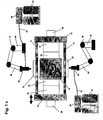
- FIGS. 1a and 1b are schematic representations of a closing unit 10 in opened ( FIG. 1a ) and closed ( FIG. 1b ) Position shown.
- the overall system should also have a plasticizing and injecting device as well as a polyurethane unit, which in the present case are indicated only schematically by the reference numerals 28 and 30.
- the closing unit can be part of a standard injection molding machine.
- the closing unit 10 of FIGS. 1 a and 1b comprises a central turning plate 16 which is rotatable about a vertical axis (indicated by an arrow of rotation).
- the insert 16 is also below (not shown) on a machine bed held axially displaceable (indicated by double arrow).
- mold halves On the sides of the cube-shaped turning plate 16 mold halves are attached, wherein in FIG. 1a and 1b the two opposite mold halves 18 and 19 are executed by a solid line. Two other mold halves 21 and 22 are shown in dashed line only because they are optional and can be omitted.
- the insert 16 is received between two platen 12 and 14, wherein the platen 14, as indicated by the double arrow, is designed to be displaced back and forth.
- the mold clamping plate 12 is fixed.
- the drives for the platen 14 and the insert 16 are not shown here.
- FIGS. 1a and 1b right outside the platen 12 is only schematically indicated the front end of a plasticizing and injection unit 28, with which a plastic melt produced and can be introduced into the cavity of the mold consisting of the mold halves 17 and 18.
- left molding tool here: mold halves 19 and 20
- the polyurethane unit 30 which comprises a mixing head 32 which is attached to the front end of a movable first robot arm 34 of a first robot 35.
- the first robot arm 34 is fixed to the floor or wall via an actuating and mounting bracket 36.
- the mixing head 32 receives from one or more containers 40 via one or more pump 38 and corresponding supply lines 31 (also called medium lines) a polyurethane material or different polyurethane starting materials, which are mixed in a mixing chamber of the mixing head 32 and then discharged from the mixing head (eg sprayed on).
- the mixing head 32 is movable by means of the movable first robot arm 34 (as in FIG FIG. 1a shown) in the space between the two mold halves 19, 20 of the open closing unit movable into or (as in FIG. 1b shown) outside the locking device positionable.
- the clamping unit 10 can be moved by moving the platens 12 and 14 between an open position (FIG. FIG. 1a ) and a closed position ( FIG. 1b ). In the closed position ( Fig. 1b ) form between the mold halves 17 and 18 or 19 and 20 mold cavities, which are indicated only schematically by dashed lines.
- thermoplastic preform is produced, which at least partially hardens before the closing unit 10 is opened again.
- FIG. 1a the closing unit 10 opened after such an injection process is shown, wherein a preform 23 is positioned further in the mold half 18.
- the mixing head 32 is brought by means of the robot arm 34 into the space between the mold halves 19 and 20 for spraying the cavity surface of the mold half 20 with a Potyurethan material.
- the turning plate 16 first rotates 90 ° counterclockwise in order to move the already completed composite part 23 'out of the region of the closing unit and to be able to better remove it from the cavity of the mold half 19. A corresponding removal device is not shown in the figures.
- the insert 16 is further at 90 ° to the Turned clockwise, so that now the mold half 18 comes together with the pre-molded part 23 against the mold half 20 to lie, which has been sprayed with the polyurethane material.
- the empty cavity of the mold half 19 is positioned opposite the mold half 17.
- the closing unit 10 is closed again.
- the still, unreacted polyurethane material applied to the cavity surface of the mold half 20 is pressed onto the preform and thus spreads over the surface of the preform 23 in the area defined by the cavity.
- Parallel with the closing unit 10 is completely closed, the mold is closed in turn thermoplastic thermoplastic melt introduced on the opposite side.
- the clamping unit 10 is opened again and proceeded as described above, i.
- the insert is first rotated 90 °, removed the finished composite part and then rotated by a further 90 ° counterclockwise. Again, the cavity surface of the mold half is sprayed with polyurethane material and a re-closing started.
- thermoplastic substrate material pre-molded part
- a finished composite part can be produced in the same cycle.
- the mold half 21 an activation process for the surface of the thermoplastic substrate can be performed.
- a plasma treatment process, a flame treatment process or a coating process are suitable in an excellent way.
- a release agent is first applied to the cavity surface with a device (not shown) so that the polyurethane material can be easily released from the cavity surface even after its partial or complete cure .
- the polyurethane unit may be formed in various ways. It can be mixed a variety of materials and switching options can be provided so that different combinations of materials can be discharged sequentially. This makes it possible to form regions with different properties, for example different colored surfaces, different reinforcement structures, different haptics, etc.
- a lacquer layer can also be applied to the cavity surface of the polyurethane mold 20.
- clamping frame systems can optionally be integrated into the tool. Before the mold consisting of the mold halves 19 and 20 is completely closed or before the polyurethane material comes into contact with the thermoplastic substrate, this clamping frame can close the mold cavity and thus substantially seal against the outside environment. As a result, the polyurethane material can not be pushed into the tool cutting plane and remains in the cavity. By the embossing process but the air is pressed out of the cavity in an advantageous manner, so that a burr-free production of composite parts is guaranteed.
- the application process of the polyurethane can also be done externally on a film.
- the sprayed film can then be inserted into the cavity of the mold half 20 by means of a handling apparatus.
- the film can be fixed for example on a tenter. This clamping frame is completely inserted into the polyurethane mold half.
- the advantage here is that the polyurethane mold half does not need to be sprayed with release agent, since the film itself can act as a release agent.
- the spraying process on the film in a separate booth next to the Injection molding machine The spraying on the film can be done parallel to the injection cycle, so that the cycle time is further reduced.
- the spraying process when using a film is also possible in a horizontally aligned manner, so that no bleeding or slippage of the PU layer is to be feared. It should be noted, however, that the polyurethane material in the unreacted state with the film is introduced into the cavity of the mold half 20 and then pressed onto the thermoplastic substrate again.
- an insert for a mold half can also be provided for this purpose.
- the externally sprayed Kavticiansober Structure or the use of the polyurethane mold half would first fixed on the platen or the mold half, by means of a mechanical or hydraulic quick-clamping system.
- a fixation with the known tandem technology can be done via bayonet system.
- the surface of another half of the mold or another insert can be cleaned, separated, painted if necessary and sprayed with a PUR system.
- the replacement of the polyurethane mold half takes place. Also, the mold half can be removed together with the component and the component only then be removed from the mold.
- An exchange of a mold half 20 or the use of a corresponding insert for the mold half 20 would also allow a different surface structure from shot to shot. Moreover, the introduction of release coating and PUR spray system could be done in a sealed cabin.
- FIGS. 1c and 1d A somewhat modified embodiment of an alternative method is disclosed in U.S. Patent Nos. 4,378,355 FIGS. 1c and 1d shown.
- the same reference numerals designate the same, in the Fig. 1a and 1b shown elements of the plant.
- a clamping unit 10 with a fixed 12, a movable 14 and a reversing plate 16 (rotatable and axially movable) is shown, now on each side of the insert 16, a mold half 18, 19, 21 and 22 are arranged.
- two plasticizing and injection units 28 and 29 for forming preforms in the cavities of the mold halves 17 and 18 or 19 and 20 are provided.
- two PUR systems with mixing heads 32, 33, robot arms 34, 44 of robots 35, 45, which are stably fixed (fasteners 36 and 37), containers 40, 41, pumps 38, 39 and PUR media lines 31, 42 are provided.
- the embodiment in Figure 1e is different from the one in the FIGS. 1 c and 1d merely in that the two mixing heads 32 and 33 are supplied by a polyurethane system with containers 40 and pump 38.
- a switching unit 43 is provided for alternately supplying the two mixing heads 32 and 33.
- This embodiment is particularly suitable when the spraying process for applying the polyurethane material is only short in comparison to the production of the preforms. Then the time to spray the Kavticiansober Designm is sufficient with only a PUR system.
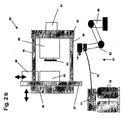
- a further embodiment of a closing unit of an injection molding machine, with which a further embodiment of the method according to the invention can be realized, is disclosed in US Pat FIGS. 2a and 2 B shown.
- a closing unit 50 with a fixed platen 52 and a movable platen 54 is shown.
- the movable platen 54 is movably guided by four bars 56.
- An injection opening of the fixed platen 52 is associated with the end portion of a pasting and injection unit 51.
- a sliding table assembly 57 is fixed schematically, which - as in FIG. 2 indicated by double arrow - can be moved up and down.
- the sliding table assembly 57 carries two mold halves 59 and 60.
- a further mold half 58 is arranged on the fixed platen 52. Depending on the position of the sliding table arrangement 57, this mold half 58 can interact with the mold half 59 or with the mold half 60.
- FIGS. 2a and 2 B schematically also a polyurethane unit 70 is indicated, which has a mixing head 74 which receives via a supply line 75 of one or more containers 78 by means of one or more pumps 77 starting material. This material is mixed together and discharged in the mixing head 74.
- the mixing head 74 disposed at the forward end of a robotic arm 82 is movable by means of a robot 80.
- a polyurethane material can be applied to the cavity surface of the mold half 60 by means of the mixing head 74.
- the closing unit 50 is opened. In this case, the preform remains in the mold half 58.
- the sliding table is moved upward, so that provided with the polyurethane material mold half 60 comes exactly opposite to the mold half 58 to lie.
- the closing unit 50 is closed again, whereby in the final phase of the movement, the polyurethane material presses against the pre-molded part in a second cavity.
- the mold clamping plate is opened again and the sliding table 57 is moved downwards. Now the finished composite part can be removed and a new cycle started.
- FIG. 2a and 2 B differs in terms of those in FIG. 2a and 2 B from the one in FIG. 1a and 1b only in that instead of a reversing plate assembly now a sliding table is used.
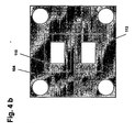
- FIG. 3 and 4a and 4b Another embodiment, now using a turntable, is based on the Figures 3 and 4a and 4b.
- a closing unit 100 with a fixed 104 and a movable platen 102 is shown, wherein the movable platen 102 can be moved to four spars 106 back and forth.
- the movable platen 102 also carries a turntable assembly 114, on which two mold halves 111 and 112 are arranged. Opposite on the fixed platen 104, two mold halves 110 and 113 are also formed.
- a plasticizing and injection unit 108 is provided, with which a plastic melt material can be introduced into the cavity of a closed, consisting of the mold halves 110 and 111 mold.
- a polyurethane unit 120 which has a mixing head 122, which is arranged on a movable robot arm 124.
- the robotic arm 124 is movably mounted on a bracket 126.
- the mixing head 122 receives the corresponding starting materials from pumps 128 and containers 130 via the supply line or several supply lines, mixes them and discharges the mixture onto a cavity surface.
- a melt is filled after closing the closing unit 100 in a still empty cavity of the mold consisting of the mold halves 110 and 111 by docking the plasticizing and injection device 108.
- the closing unit 100 is opened by driving up the movable platen 102, wherein (as in FIG. 3 schematically indicated), the pre-molded part 109 is received in the mold half 111 and moves together with the movable platen 102 to the left.
- the mixing head 122 of the polyurethane unit 120 is moved in front of the cavity surface of the mold half 113 to apply a polyurethane material to the cavity surface.
- the turntable assembly 114 is rotated, so that now comes with the preform mold half 111 opposite the coated with the not yet fully reacted polyurethane mold half 113 to lie.
- the closing unit 100 can be closed again, as a result of which the polyurethane material presses on the preform and coats it in the cavity space.
- Parallel is in the upper mold of the FIG. 3 again formed a preform.
- the finished composite part of the mold half 112 or the mold half 113 can be removed first.
- turntable 114 can be rotated and a new cycle started. In this way, in the arrangement in FIG. 3 At the top of each cycle a preform formed and at the bottom of a formed from the preform and the coated polyurethane material composite part.
- a unit for applying a release agent may be provided on the cavity surface of the mold half 113.
- further units for cleaning the Kavticiansobervid or for removal of individual parts may be provided.
- the polyurethane unit 120 itself may be formed in different, so that polyurethane materials with a variety of properties in parallel or successively on the cavity surface of the mold half 113 can be applied.
- the two mold halves 112 and 111 are identical.
- the mold halves 110 and 113 are formed differently.
- the present invention allows a use of polyurethane spray technology in the production of multi-component composite components with high-quality polyurethane surface structures.
- low tool wear in particular at the tool parting plane, can be ensured by the low-pressure method.
- embossing is also a very thin-walled design of a polyurethane layer on a thermoplastic carrier possible.
- no venting cavities are necessary. This allows for greater design freedom.
Landscapes
- Engineering & Computer Science (AREA)
- Mechanical Engineering (AREA)
- Manufacturing & Machinery (AREA)
- Injection Moulding Of Plastics Or The Like (AREA)
- Casting Or Compression Moulding Of Plastics Or The Like (AREA)
Description
- Die vorliegende Erfindung betrifft ein Verfahren zur Herstellung eines beschichteten Verbundbauteils.
- Bei solchen Verfahren werden beispielsweise aus einem thermoplastischen Kunststoffträger mittels einer Beschichtung Verbundbauteile hergestellt. Die Beschichtung kann dabei beispielsweise aus einem Polyurethan bestehen, mit welchem man gewünschte Oberflächenstrukturen oder Haptiken erzeugen kann.
- Bisher gibt es insbesondere zwei bekannte Verfahren, mit denen man entsprechende Polyurethan-Oberflächen bei einem Verbundbauteil ausbilden kann. Zum einen ist es bekannt, ein thermoplastisches Kunststoffsubstrat in einer Kavität so anzuordnen, dass noch ein Spalt zwischen dem Substrat und der Kavitätswand besteht. In diesen Spalt wird ein Polyurethan-Material eingefüllt. Diesen Vorgang nennt man auch Überfluten. Ein solches Verfahren ist in der
DE 10 2005 013 975 A1 beschrieben. - Anderseits kann man ein Verfahren verwenden, bei dem in einem ersten Arbeitsschritt eine Polyurethan-Haut ausgebildet wird. Eine solche Haut kann man beispielsweise mit einem sogenannten Slush-Prozess oder einem Sprühprozess herstellen. Bei einem Slush-Verfahren wird ein Kunststoffpulver oder -granulat in einer Galvanoform derart aufgeschmolzen, dass sich das Material unter Ausbildung einer entsprechenden Schicht an der Formwandung anlagert. Beim Aufsprühen eines PUR-Materials wird dieses mittels eines Sprühvorgangs auf eine entsprechende Oberfläche aufgetragen. Bei beiden Verfahren wird die Haut nach dem Ausreagieren aus der Form entnommen und in einem separaten Verarbeitungsschritt mit einem thermoplastischen Kunststoffmaterial hinterspritzt. Dieses Verfahren ist auch als "SkinForm-Verfahren" (SkinForm = Marke der Krauss-Maffei Kunststofftechnik GmbH) bekannt. Ein solches Verfahren zum Hinterspritzen einer Haut ist in der
DE 699 05 745 T2 oder deEP 0 995 568 A1 beschrieben. In dem ersten Dokument sind verschiedene Alternativen für ein Verfahren zum Herstellen eines mehrschichtigen synthetischen Formteils beschrieben, bei denen zunächst - beispielsweise über ein Sprühverfahren - eine Haut hergestellt wird, die dann in einem zweiten Produktionsschritt auf unterschiedliche Art und Weise hinterspritzt wird. - Bei den heute bekannten Verfahrensabläufen zum gratfreien Überfluten eines Thermoplast-Trägerbauteils mit einem Polyurethan-Material in einem vollautomatischen Zyklus wird in der Regel ein geschlossenes Formwerkzeug mit einer verschlossenen Kavität verwendet. Problematisch ist hierbei die Realisierung einer notwendigen Entlüftung der Kavität zum Einfüllen des Polyurethan-Materials. Nahezu alle Polyurethan-Systeme müssen gezielt entlüftet werden, was gerade bei geschäumten Systemen entscheidend ist. Jede Entlüftung fordert zudem auch eine - wenn auch geringfügige - Nachbearbeitung des Bauteils, um die in den Entlüftungskavitäten ausgebildeten Angüsse bzw. Nasen zu entfernen. Überdies werden durch die notwendige Entlüftung die Designmöglichkeiten oftmals eingeschränkt.
- Darüber hinaus sind seit langer Zeit Vorrichtungen und Verfahren zur Herstellung von mit Thermoplastmaterial hinterspritzer Dekormaterialien bekannt. Ein Beispiel dieser Technologie ist aus der
EP 0 543 085 bekannt. Gemäß der darin beschriebenen Lehre wird eine Dekorschicht zwischen zwei Werkzeugformen eingespannt. Auf eine der Werkzeugformen wird ein noch nicht ausgehärtetes Thermoplastmaterial aufgebracht, welches beim Schließen der der Werkzeugformen durch einen Prägeschritt entsprechend der Kavitätsausgestaltung der Werkzeugform über die Dekorschicht verprägt wird. Nach dem Abkühlen kann das Dekor-Formteil entnommen werden, wobei das Thermoplastmaterial den Träger darstellt. Insofern ist dieses Verfahren dem vorgenannten SkinForm-Verfahren sehr ähnlich. - Aufgabe der vorliegenden Erfindung ist es, ein Verfahren anzugeben, bei dem die oben genannten Nachteile bei der Herstellung von Verbundbauteilen vermieden werden.
- Diese Aufgabe wird durch die im Anspruch 1 genannten Merkmale verfahrensmäßig gelöst.
- Ein Kerngedanke der vorliegenden Erfindung ist darin zu sehen, dass das PolyurethanMaterial nicht in eine geschlossene Form eingebracht, sondern auf eine offene formhälfte eines Formwerkzeugs aufgebracht bzw. aufgesprüht wird. Anschließend wird diese, mit dem noch nicht ausreagierten Polyurethan-Material benetzte Werkzeughälfte mit einer anderen Werkzeughälfte, in der beispielsweise ein den thermoplastischen Kunststoffträger bildendes Thermoplast-Substrat enthalten ist, verschlossen. Das Polyurethan-Material wird dabei auf das Thermoplast-Substrat (auch Vorspritzling genannt) aufgepresst oder aufgedrückt und reagiert unter Ausbildung eines Verbundkörpers damit aus. Durch diesen Niederdruck-Verpressvorgang kann eine deutlich verbesserte Entlüftung der Werkzeugkavität sichergestellt werden. Natürlich kann die Polyurethan-Formwerkzeughälfte auch durch einen Prägevorgang auf die Thermoplast-Werkzeughälfte aufgedrückt werden, wodurch das Polyurethan durch den Prägeschritt in der Kavität verteilt wird.
- Vorzugsweise erfolgt das Aufbringen der Polyurethan-Schicht auf die Kavitätsoberfläche zyklusgleich zum Einbringen der Schmelze in das erste Formwerkzeug. In diesem Fall kann bei jedem Takt sowohl ein Vorspritzling wie auch ein beschichtetes Verbundprodukt hergestellt werden. Alternativ kann das Aufbringen der PolyurethanSchicht auf die Kavitätsoberfläche auch nach dem Einbringen der Schmelze in das erste Formwerkzeug und dem nachfolgenden Öffnen des ersten Formwerkzeugs erfolgen. So dauert der Herstellungsvorgang möglicherweise etwas länger, insbesondere, wenn man die Zeit zum Aufbringen des Polyurethan-Materials auf dieFormwerkzeugoberfläche abwarten muss, bevor das Formwerkzeug wieder geschlossen werden kann. Allerdings hat diese Verfahrensalternative den Vorteil, dass man evtl. mit nur einem Werkzeug auskommen kann.
- Beim Aufbringen des Polyurethan-Materials auf die Kavitätsoberfläche einer offenen. Werkzeughälfte kann dieses durch Sprühen öder Aufspritzen geschehen. Alternativ kann auch eine Trägerschicht, beispielsweise in Form einer Folie, verwendet werden, auf die außerhalb des Formwerkzeugs das Polyurethan-Material aufgetragen wird oder aufgetragen worden ist. Nachfolgend wird die Trägerschicht, also die Folie, zusammen mit dem Polyurethan in die Kavität des Formwerkzeugs eingelegt. Die Folie kann dabei in einem Spannrahmen fixiert sein. Unabhängig davon, ob das Polyurethan-Material unmittelbar auf die Kavitätsoberfläche eines Formwerkzeugs aufgetragen wird oder aber auf eine Trägerschicht aufgebracht wird, kann ein Polyurethan-Mischkopf oder -sprühkopf verwendet werden, mit dem das Aufbringen unmittelbar erfolgt.
- Vorzugsweise können mehrere unterschiedliche Polyurethan-Materialien nacheinander (beispielsweise in verschiedenen Bereichen) auf die Kavitätsoberfläche aufgesprüht werden. So kann man lokal unterschiedliche Haptiken oder lokale Verstärkungen realisieren. Auch können Materialien mit unterschiedlichen Eigenschaften und Farben verwendet werden. Überdies ist es möglich, hochviskose und/oder hochbefüllte Polyurethan-Systeme mit diesem Verfahren zu verarbeiten.
- Das Umsetzen des das Substrat bildende Spritzgussteils kann durch Verdrehen beispielsweise mit einem Drehtisch, einer Indexplattenanordnung der einer Wendeplatte geschehen oder aber durch Verschieben mit einer Schiebetischanordnung. Die Vorrichtungen eines Drehtisches, einer Indexplattenanordnung oder einer Wendeplatte, wie auch eines Schiebetisches sind dabei hinlänglich aus dem Stand der Technik bekannt. Wird das Substrat nicht umgesetzt, sondern vielmehr die mit dem Polyurethan-Material versehene Formwerkzeughälfte der Formhälfte mit dem Spritzgussteil zugeordnet, so kann dies ebenfalls mittels einer Drehtisch-, Indexplatten, Wendeplatten oder Schiebetischanordnung geschehen.
- Um ein einfaches Ablösen des Polyurethan-Materials von der Kavitätsoberfläche sicherzustellen, kann vor dem Auftragen des Polyurethan-Materials ein Trennmittel auf die Kavitätsoberfläche aufgebracht werden. Bei der Verwendung einer Trägerfolie kann diese gleichzeitig als Trennmedium vorgesehen sein.
- Zudem kann vor dem Aufbringen des Polyurethan-Materials eine Lackschicht auf die Kavitätsoberfläche aufgetragen werden. Mit einem solchen als "In-Mould-Technik" bezeichneten Verfahren ist es möglich, lackierte Oberflächen Polyurethan-Oberflächen zu generieren.
- Natürlich können in die Kavität auch andere Einlegermaterialien vor dem Einfüllen des Polyurethan-Materials eingebracht werden.
- Um zu verhindern, dass das Polyurethan-Material beim Schließen der beiden Formwerkzeughälften und Aufdrücken bzw. Verprägen des Polyurethans auf das Substrat aus der Kavität herausgepresst wird, ist es möglich, einen Spannrahmen zwischen der das Substrat aufweisenden Formwerkzeughälfte und der Polyurethan-Formwerkzeughälfte zu verwenden. Ein solcher Spannrahmen sollte die Kavität, insbesondere vor dem eigentlichen Prägevorgang, gegenüber der Außenumgebung abschließen. Alternativ kann hierbei auch ein Tauchwerkzeug verwendet werden.
- Eine weitere vorteilhafte Ausführungsform ist dadurch gekennzeichnet, dass zum Einfügen in die Formwerkzeughälfte des Polyurethan-Formwerkzeugs ein Einsatz vorgesehen ist, der die Kavitätsausnehmung zumindest im Wesentlichen umfasst. Dabei kann das Polyurethan-Material außerhalb der Schließeinheit in den Einsatz eingebracht werden. Anschließend wird der Einsatz zusammen mit dem PolyurethanMaterial in die Formwerkzeughälfte eingelegt und anschließend der Schritt zum Schließen des Formwerkzeugs und zum Aufdrücken des Polyurethan-Materials auf das thermoplastische Substrat durchgeführt. Diese Ausführungsform hat den Vorteil, dass eine Vielzahl solcher Einsätze vorgesehen werden können, die parallel in den unterschiedlichen Verfahrensschritten handhabbar sind. Beispielsweise ist es möglich, während eines Prägevorgangs einen anderen Einsatz außerhalb der Schließeinheit bereits wieder zu besprühen. Überdies ist es möglich, die Einsätze in ihrer Form und Oberflächengestaltung unterschiedlich auszubilden.
- Bei der Verwendung eines solchen Einsatzes sollte vorzugsweise die Fixierung der Einsätze in der Formwerkzeughälfte möglich sein. Dazu könnte beispielsweise ein Schnellspann- oder Bajonettsystem verwendet sein.
- Die Erfindung soll nachfolgend anhand von verschiedenen Ausführungsbeispielen und mit Bezug auf die beiliegenden Zeichnungen näher erläutert werden. Die Zeichnungen zeigen in
- Figur 1a
- eine Schließeinheit einer Spritzgießmaschine in schematischer Darstellung, anhand der das erfindungsgemäße Verfahren erläutert wird,
- Figur 1b
- die Schließeinheit aus
Figur 1a in geschlossener Position, - Figur 1c
- eine Schließeinheit wie in
Fig. 1a dargestellt in schematischer Darstellung, der zwei Plastifizier- und Einspritzeinheiten zugeordnet sind, wobei die Schließeinheit geschlossen ist, - Figur 1d
- die schematisch dargestellte Schließeinheit gemäß
Fig. 1c in offener Stellung, - Figur 1e
- eine schematisch dargestellte Schließeinheit wie in
Fig. 1c , wobei nunmehr zwei Mischköpfe von einer Polyurethan-Anlage versorgt werden, - Figur 2a
- eine weitere Ausführungsform einer schematisch dargestellten Schließeinheit einer Spritzgießmaschine mit einer Schiebetischanwendung in einer ersten Position, anhand der eine weitere Ausführungsform des erfindungsgemäßen Verfahrens erläutert wird,
- Figur 2b
- die Ausführungsform gemäß
Fig. 2a einer schematisch dargestellten Schließeinheit einer Spritzgießmaschine in einer zweiten Position, - Figur 3
- eine weitere Ausführungsform einer Schließeinheit in schematischer Darstellung in einer schematischen Darstellung mit einer Drehtischanwendung, mit der eine weitere Ausführungsform eines erfindungsgemäßen Verfahrens dargestellt wird und
- Figur 4a und 4b
- eine schematische Draufsichten auf die Aufspannplatten der Schließeinheit aus
Figur 3 . - In den
Figuren 1a und1b sind schematische Darstellungen einer Schließeinheit 10 in geöffneter (Figur 1a ) und geschlossener (Figur 1b ) Position dargestellt. Die Gesamtanlage sollte neben der Schließeinheit 10 zudem noch eine Plastifizier- und Einspritzeinrichtung sowie eine Polyurethan-Einheit aufweisen, die vorliegend lediglich schematisch mit den Bezugsziffern 28 und 30 angedeutet sind. Diese sehr grobe Skizzierung ist für die Beschreibung des erfindungsgemäßen Verfahrens jedoch ausreichend. Die Schließeinheit kann dabei Bestandteil einer Standard-Spritzgießmaschine sein. - Die Schließeinheit 10 der
Figuren 1 a und 1 b umfasst eine zentrale Wendeplatte 16, die um eine vertikale Achse drehbar ausgebildet ist (angedeutet durch Rotationspfeil). Die Wendeplatte 16 ist unten (nicht dargestellt) auf einem Maschinenbett zudem axial verschiebbar gehalten (angedeutet durch Doppelpfeil). - An den Seiten der würfelförmig ausgestalteten Wendeplatte 16 sind Formwerkzeughälften befestigt, wobei in
Figur 1a und1b die beiden gegenüberliegenden Formhälften 18 und 19 mit durchgezogener Linie ausgeführt sind. Zwei weitere Formwerkzeughälften 21 und 22 sind lediglich mit gestrichelter Linie dargestellt, da sie optional sind und weggelassen werden können. - Die Wendeplatte 16 ist zwischen zwei Formaufspannplatten 12 und 14 aufgenommen, wobei die Formaufspannplatte 14, wie mit dem Doppelpfeil angedeutet, hin und her verschieblich ausgeführt ist. Die Formaufspannplatte 12 ist fest angeordnet. Die Antriebe für die Formaufspannplatte 14 und die Wendeplatte 16 sind vorliegend nicht dargestellt.
- Zwischen den beiden Aufspannplatten 12 und 14 sind 4 Holme 11 angeordnet, von denen in den Figuren lediglich zwei zu erkennen sind. An beiden Formaufspannplatten 12 und 14 sind Formwerkzeughälften 17 und 22 befestigt, welche mit den jeweils gegenüber liegenden Formwerkzeughälften der Wendeplatte 16 in geschlossenem Zustand der Schließeinheit zur Ausbildung jeweils einer Kavität zusammenwirken.
- In den
Figuren 1a und1b rechts außerhalb der Formaufspannplatte 12 ist nur schematisch das vordere Ende einer Plastifizier- und Einspritzeinheit 28 angedeutet, mit welcher eine plastische Kunststoffschmelze erzeugt und in die Kavität des Formwerkzeugs bestehend aus den Formwerkzeughälften 17 und 18 eingebracht werden kann. - Dem in den
Figuren 1a und1b linken Formwerkzeug (hier: Formwerkzeughälften 19 und 20) ist die Polyurethan-Einheit 30 zugeordnet, welche einen Mischkopf 32 umfasst, der am vorderen Ende eines beweglichen ersten Robotarms 34 eines ersten Roboters 35 befestigt ist. Der erste Robotarm 34 ist über einen Betätigungs- und Befestigungsbock 36 am Boden oder an der Wand fixiert. - Der Mischkopf 32 erhält aus einem oder mehreren Behältnissen 40 über eine oder mehrere Pumpe 38 und entsprechende Versorgungsleitungen 31 (auch Mediumleitungen genannt) ein Polyurethan-Material bzw. verschiedene Polyurethan-Ausgangsmaterialien, die in einer Mischkammer des Mischkopfes 32 vermischt und anschließend aus dem Mischkopf ausgebracht (z. B. aufgesprüht) werden. Der Mischkopf 32 ist mittels des beweglichen ersten Robotarms 34 (wie in
Figur 1a dargestellt) in den Raum zwischen die zwei Formhälften 19, 20 der geöffneten Schließeinheit hinein verfahrbar oder (wie inFigur 1b dargestellt) außerhalb der Schließeinrichtung positionierbar. - Das mit der in den
figuren 1a und1b gezeigten Schließeinheit durchgeführte Verfahren wird nachfolgend beschrieben: - Die Schließeinheit 10 kann durch Bewegen der Aufspannplatten 12 und 14 zwischen einer geöffneten Position (
Figur 1a ) und einer geschlossenen Position (Figur 1b ) verfahren werden. In der geschlossenen Position (Fig. 1b ) bilden sich zwischen den Formwerkzeughälften 17 und 18 bzw. 19 und 20 Formkavitäten aus, die nur schematisch strichliniert angedeutet sind. - Zunächst wird in der Position der
Figur 1b nach dem Andocken der Plastifizier- und Einspritzeinheit 28 an das Formwerkzeug mit den Formwerkzeughälften 17 und 18 eine Schmelze in die Kavität des so gebildeten Formwerkzeugs eingespritzt. Auf diese Art und Weise wird ein thermoplastischer Vorformling erzeugt, welcher zumindest teilweise aushärtet, bevor die Schließeinheit 10 wieder geöffnet wird. - In
Figur 1a ist die nach einem solchen Einspritzvorgang geöffnete Schließeinheit 10 dargestellt, wobei ein Vorformling 23 weiter in der Formhälfte 18 positioniert ist. - Nach dem Öffnen der Schließeinheit 10 wird der Mischkopf 32 mittels des Robotarms 34 in den Zwischenraum zwischen den Formwerkzeughälften 19 und 20 zum Besprühen der Kavitätsoberfläche der Formwerkzeughälfte 20 mit einem Potyurethan-Material gebracht. Gleichzeitig dreht die Wendeplatte 16 zunächst um 90° gegen den Uhrzeigersinn, um das bereits fertiggestellte Verbundteil 23' aus dem Bereich der Schließeinheit herauszubewegen und besser aus der Kavität der Formwerkzeughälfte 19 entnehmen zu können. Eine entsprechende Entnahmevorrichtung ist in den Figuren nicht dargestellt. Sodann wird die Wendeplatte 16 weiter um 90° gegen den Uhrzeigersinn gedreht, so dass nunmehr die Formwerkzeughälfte 18 zusammen mit dem Vorspritzling 23 gegenüber der Formwerkzeughälfte 20 zu liegen kommt, welche mit dem Polyurethanmaterial besprüht worden ist.
- Andererseits ist nunmehr - nach einer 180° Drehung - die leere Kavität der Formwerkzeughälfte 19 gegenüberliegend der Formwerkzeughälfte 17 positioniert. Nach dem Zurückziehen des Robotarmes 34 wird die Schließeinheit 10 wieder geschlossen. Während des Schließvorgangs wird das auf der Kavitätsoberfläche der Formwerkzeughälfte 20 aufgebrachte noch, nicht ausreagierte Polyurethanmaterial auf den Vorspritzling gedrückt und verteilt sich somit in dem durch die Kavität definierten Bereich über die Oberfläche des Vorformlings 23. Parallel wird bei vollständig geschlossener Schließeinheit 10 in das geschlossene Formwerkzeug auf der gegenüberliegenden Seite wiederum thermoplastische Kunststoffschmelze eingebracht.
- Nachdem zumindest teilweisen Ausreagieren des Polyurethanmaterials auf dem Vorformling sowie dem zumindest teilweisen Aushärten des thermoplastischen Substrats im anderen Formwerkzeug (Formwerkzeughälften 17 und 18) wird die Schließeinheit 10 wieder geöffnet und wie oben beschrieben weiter verfahren, d.h. die Wendeplatte wird zunächst um 90° gedreht, das fertiggestellte Verbundteil entnommen und sodann um weitere 90° gegen den Uhrzeigersinn verdreht. Wiederum wird die Kavitätsoberfläche der Formwerkzeughälfte mit Polyurethanmaterial besprüht und ein erneuter Schließvorgang gestartet.
- So können bei jedem Schließvorgang zyklusgleich ein thermoplastisches Substratmaterial (Vorspritzling) wie auch ein fertiges Verbundteil hergestellt werden. Der Vorteil ist nun darin zu finden, dass während des Zusammenfahrens der beiden Formwerkzeughälften 19 und 20 ein Entlüftungsvorgang der Kavität sichergestellt ist und das Polyurethanmaterial gleichmäßig auf den Vorspritzling aufgeprägt wird.
- Natürlich kann das mit Bezug auf die
Figuren 1a und1b beschriebene Verfahren noch weiter ausgebaut werden. Beispielsweise können bei der Verwendung von vier gleichen Formwerkzeughälften 18, 19, 21 und 22 weitere Arbeitsschritte hinzugefügt werden. So kann an der Position der Formwerkzeughälfte 21 ein Aktivierungsvorgang für die Oberfläche des thermoplastischen Substrats durchgeführt werden. Dafür eignen sich ein Plasmabehandlungsvorgang, ein Beflammungsvorgang oder ein Beschichtungsvorgang in hervorragender Weise. Auch kann vor dem Aufbringen des Polyurethanmaterials auf die Kavitätsoberfläche der Formwerkzeughälfte 20 zunächst mit einer (nicht dargestellten) Vorrichtung ein Trennmittel auf die Kavitätsoberfläche aufgetragen werden, so dass sich das Polyurethan-Material auch nach dessen teilweisen oder vollständigen Ausreagieren wieder gut von der Kavitätsoberfläche lösen lässt. Sodann kann auch die Polyurethan-Einheit auf verschiedene Arten und Weisen ausgebildet sein. Es können verschiedenste Materialien vermischt sowie Umschaltmöglichkeiten vorgesehen sein, so dass unterschiedliche Materialkombinationen nacheinander ausgetragen werden können. Dadurch ist es möglich, Bereiche mit unterschiedlichen Eigenschaften, beispielsweise verschiedenen farblichen Oberflächen, verschiedenen Verstärkungsstrukturen, verschiedenen Haptiken usw. auszubilden. - Alternativ oder zusätzlich zum Aufbringen eines Trennmittels kann auch eine Lackschicht auf die Kavitätsoberfläche des Polyurethan-Formwerkzeugs 20 aufgebracht werden.
- Analog der Werkzeugtechnik für das Expansionsprägen können optional Spannrahmensysteme in das Werkzeug integriert sein. Bevor das Formwerkzeug bestehend aus den Formwerkzeughälften 19 und 20 komplett geschlossen wird bzw. bevor das Polyurethan-Material mit dem thermoplastischen Substrat in Kontakt kommt, kann dieser Spannrahmen die Werkzeugkavität verschließen und so gegenüber der Außenumgebung im wesentlichen abdichten. Dadurch kann das Polyurethan-Material nicht in die Werkzeügtrennebene gedrückt werden und verbleibt in der Kavität. Durch den Prägevorgang wird aber in vorteilhafter Weise die Luft aus der Kavität herausgedrückt, so dass eine gratfreie Fertigung von Verbundteilen gewährleistet ist.
- Alternativ zu dem anhand der
Figuren 1a und1b beschriebenen Verfahren kann der Aufbringvorgang des Polyurethans auch extern auf eine Folie erfolgen. Die besprühte Folie kann dann mittels einer Handlingsapparatur in die Kavität der Formwerkzeughälfte 20 eingelegt werden. Dazu kann die Folie beispielsweise auf einem Spannrahmen fixiert sein. Dieser Spannrahmen wird komplett in die Polyurethan-Werkzeughälfte eingesetzt. Vorteilhaft hierbei ist, dass die Polyurethan-Formwerkzeughälfte nicht mit Trennmittel besprüht werden muss, da die Folie selbst als Trennmittel agieren kann. Zudem kann der Sprühvorgang auf die Folie in einer separaten Kabine neben der Spritzgießmaschine erfolgen: Der Sprühvorgang auf die Folie kann parallel zum Injektionszyklus erfolgen, so dass die Zykluszeit weiter reduzierbar ist. Nicht zuletzt ist der Sprühvorgang bei der Verwendung einer Folie auch in horizontal ausgerichteter Weise möglich, so dass kein Verlaufen oder ein Abrutschen der PUR-Schicht zu befürchten ist. Zu beachten ist jedoch, dass das Polyurethan-Material in nicht ausreagierten Zustand mit der Folie in die Kavität der Formwerkzeughälfte 20 eingebracht und dann wieder auf das thermoplastische Substrat aufgedrückt wird. - Bei kleineren Formwerkzeugen ist es überdies möglich, die Werkzeughälfte in jedem Zyklus zu tauschen. Alternativ kann dafür auch ein Einsatz für eine Formwerkzeughälfte vorgesehen sein. Bei dieser Vorgehensweise würde die extern besprüht Kavitätsoberfläche bzw. der Einsatz mit der Polyurethan-Werkzeughälfte zunächst auf der Aufspannplatte oder der Formwerkzeughälfte fixiert, und zwar mittels eines mechanischen oder hydraulischen Schnellspannsystems. Auch kann eine Fixierung mit der bekannten Tandemtechnologie über Bajonettsystem erfolgen. Parallel kann bei einer anderen Werkzeughälfte oder einem anderen Einsatz die Oberfläche gereinigt, eingetrennt, ggf. lackiert und mit einem PUR-System besprüht werden.
- Nach Entnahme der Bauteile erfolgt das Auswechseln der Polyurethan-Formwerkzeughälfte. Auch kann die Formwerkzeughälfte zusammen mit dem Bauteil entnommen und das Bauteil erst anschließend entformt werden.
- Ein Austausch einer Formwerkzeughälfte 20 bzw. die Verwendung eines entsprechenden Einsatzes für die Formwerkzeughälfte 20 würde auch eine unterschiedliche Oberflächenstruktur von Schuss zu Schuss ermöglichen. Überdies könnte das Einbringen von Trennmittellack und PUR-Sprühsystem in einer abgeschlossenen Kabine erfolgen.
- Eine etwas abgeänderte Ausführungsform für ein alternatives Verfahren ist in den
Figuren 1c und1d dargestellt. Dabei bezeichnen die gleichen Bezugszeichen die selben, in denFig. 1a und1b gezeigten Elemente der Anlage. - Wiederum ist eine Schließeinheit 10 mit einer festen 12, einer beweglichen 14 und einer Wendeplatte 16 (drehbar und axial beweglich) dargestellt, wobei nunmehr an jeder Seite der Wendeplatte 16 eine Formwerkzeughälfte 18, 19, 21 und 22 angeordnet sind. Im Unterschied zur Anlage in den
Figuren 1a und1b sind nunmehr zwei Plastifizier- und Einspritzeinheiten 28 und 29 zum Ausbilden von Vorspritzlingen in den Kavitäten der Formwerkzeughälften 17 und 18 bzw. 19 und 20 vorgesehen. Zudem sind nun nicht nur eine PUR-Anlage, sondern zwei PUR-Anlagen mit Mischköpfen 32, 33, Robotarmen 34, 44 von Robotern 35, 45, die stabil befestigt sind (Befestigungen 36 und 37), Behältern 40, 41, Pumpen 38, 39 und PUR-Medienleitungen 31, 42 vorgesehen. - Mit dieser Anlage wird in einem anderen Verfahrensablauf gearbeitet. So werden im ersten Takt (
Fig. 1c ) in den geschlossenen Kavitäten der Formwerkzeuge 17 und 18 bzw. 19 und 20 zunächst zwei Vorspritzlinge geformt. Gleichzeitig wird mittels der Mischköpfe 32 und 33 Polyurethan-Material auf die Kavitätsoberflächen der Formwerkzeughälften 21 und 22 ausgesprüht. Dieser Vorgang kann parallel zum Einbringen und Aushärten des Material für die Vorspritzlinge geschehen. Sind die Vorspritzlinge 24 und 25 ausreichend ausgehärtet, so wird die Schließeinheit 10 geöffnet, wobei die Vorspritzlinge 24 und 25 in den Formwerkzeughälften 17 bzw. 20 verbleiben, und die Wendeplatte um 90° gegen den Uhrzeigersinn gedreht. Anschließend wir die Schließeinheit wieder geschlossen, wodurch sich das noch nicht ausgehärtete Polyurethan-Material auf die in den Formwerkzeughälften 17 und 20 verbliebenen Vorspritzlinge aufpresst. Nachdem das Polyurethan-Material zumindest teilweise ausgehärtet ist, kann die Schließeinheit wieder geöffnet werden und die fertigen Produkte sind zu entnehmen. Anschließend wird die Wendeplatte wieder 90° zurück- oder weitergedreht und der Zyklus wiederholt sich. Auf diese Weise können mit einer Standard-Maschine zyklusgleich jeweils 2 Produkte hergestellt werden. Dieses Produktionsweise ist insbesondere dann günstig, wenn beispielsweise zwei spiegelbildlich symmetrische Stücke herzustellen sind. - Die Ausführungsform in
Figur 1e unterscheidet sich von derjenigen in denFiguren 1 c und 1d lediglich dadurch, dass die beiden Mischköpfe 32 und 33 von einer Polyurethananlage mit Behältern 40 und Pumpe 38 versorgt werden. Dabei ist eine Umschalteinheit 43 zur wechselweisen Versorgung der beiden Mischköpfe 32 und 33 vorgesehen. Diese Ausführungsform eignet sich besonders dann, wenn der Sprühvorgang zum Aufbringen des Polyurethan-Materials im Vergleich zum Herstellen der Vorformlinge nur kurz ist. Dann reicht die Zeit zum Besprühen der Kavitätsoberflächem auch mit nur einer PUR-Anlage aus. - Eine weitere Ausführungsform einer Schließeinheit einer Spritzgießmaschine, mit der eine weitere Ausführungsform des erfindungsgemäßen Verfahrens realisiert werden kann, ist in den
Figuren 2a und2b dargestellt. - In diesen Figuren ist eine Schließeinheit 50 mit einer festen Formaufspannplatte 52 und einer beweglichen Formaufspannplatte 54 gezeigt. Die bewegliche Formaufspannplatte 54 ist über vier Holme 56 beweglich geführt. Einer Einspritzöffnung der festen Formaufspannplatte 52 ist der endseitige Teil einer Pastifizier- und Einspritzeinheit 51 zugeordnet.
- An der beweglichen Formaufspannplatte 54 ist schematisch eine Schiebetischanordnung 57 befestigt, die sich - wie in
Figur 2 mit Doppelpfeil angedeutet - nach oben und unten verschieben lässt. Die Schiebetischanordnung 57 trägt zwei Formwerkzeughälften 59 und 60. - An der festen Formaufspannplatte 52 ist eine weitere Formwerkzeughälfte 58 angeordnet. Diese formwerkzeughälfte 58 kann je nach Position der Schiebetischanordnung 57 mit der Formwerkzeughälfte 59 oder mit der Formwerkzeughälfte 60 zusammenwirken.
- In
Figuren 2a und2b ist schematisch auch eine Polyurethan-Einheit 70 angedeutet, die einen Mischkopf 74 aufweist, der über eine Versorgungsleitung 75 von einem oder mehreren Behältern 78 mittels einer oder mehrerer Pumpen 77 Ausgangsmaterial erhält. Dieses Material wird im Mischkopf 74 zusammenmischt und ausgebracht. - Wiederum ist der am vorderen Ende eines Robotarms 82 angeordnete Mischkopf 74 mittels eines Roboters 80 bewegbar.
- Das erfindungsgemäße Verfahren mit der in dem
Figuren 2a und2b gezeigten Vorrichtung läuft nun wie folgt ab: - Zunächst sind alle Formwerkzeughälften leer und die Schließvorrichtung 50 befindet sich in geöffnetem Zustand. Anschließend wird die Schließeinheit 50 geschlossen und die Formaufspannplatte 54 nach rechts verfahren, so dass die Formwerkzeughälfte 59 unter Ausbildung einer ersten Kavität auf der Formwerkzeughälfte 58 zu liegen kommt. In dieser Position kann ein plastisches Kunststoffmaterial mittels der Plastifizier- und Einspritzvorrichtung 51 in die Kavität eingefüllt werden.
- Gleichzeitig kann ein Polyurethan-Material mittels dem Mischkopf 74 auf die Kavitätsoberfläche der Formwerkzeughälfte 60 aufgebracht werden. Nach dem zumindest teilweisen Aushärten des thermoplastischen Substratmaterials (Vorformlings) in der Kavität der beiden Formwerkzeughälften 58 und 59 wird die Schließeinheit 50 geöffnet. Dabei verbleibt der Vorspritzling in der Formwerkzeughälfte 58. Anschließend wird der Schiebetisch nach oben verfahren, so dass die mit dem Polyurethan-Material versehene Formwerkzeughälfte 60 genau gegenüber der Formwerkzeughälfte 58 zu liegen kommt. Nun wird die Schließeinheit 50 wieder geschlossen, wodurch sich in der Endphase der Bewegung das Polyurethan-Material gegen den Vorspritzling in einer zweiten Kavität anpresst. Nach dem zumindest teilweisen Aushärten des PolyurethanMaterials wird die Formaufspannplatte wieder geöffnet und der Schiebetisch 57 nach unten verfahren. Nunmehr kann das fertige Verbundteil entnommen und ein neuer Zyklus gestartet werden.
- Auch bei dieser Ausführungsform kann mit einem Einlegerteil für die Formwerkzeughälfte 60 oder mit einer Folie als Trägerschicht gearbeitet werden. Insofern unterscheidet sich die Ausführungsform hinsichtlich derjenigen in
Figur 2a und2b von derjenigen inFigur 1a und1b lediglich dadurch, dass anstelle einer Wendeplattenanordnung nun ein Schiebetisch eingesetzt ist. - Eine weitere Ausführungsform, nunmehr unter Einsatz eines Drehtisches, ist anhand der
Figuren 3 sowie 4a und 4b beschrieben. In diesen Figuren ist eine Schließeinheit 100 mit einer festen 104 und einer beweglichen Formaufspannplatte 102 dargestellt, wobei sich die bewegliche Formaufspannplatte 102 an vier Holmen 106 hin und her verfahren lässt. Die bewegliche Formaufspannplatte 102 trägt überdies eine Drehtischanordnung 114, auf der zwei Formhälften 111 und 112 angeordnet sind. Gegenüberliegend auf der festen Formaufspannplatte 104 sind ebenfalls zwei Formhälften 110 und 113 ausgebildet. - Wiederum ist eine Plastifizier- und Einspritzeinheit 108 vorgesehen, mit der ein plastisches Schmelzematerial in die Kavität eines geschlossenen, aus den Formhälften 110 und 111 bestehenden Formwerkzeug eingebracht werden kann.
- Überdies ist auch bei dieser Ausführungsform eine Polyurethan-Einheit 120 vorgesehen, die einen Mischkopf 122 aufweist, der an einem beweglichen Robotarm 124 angeordnet ist. Der Robotarm 124 ist an einem Bock 126 beweglich betätigbar befestigt. Der Mischkopf 122 erhält von Pumpen 128 und Behältnissen 130 über die Versorgungsleitung oder mehrere Versorgungsleitungen die entsprechenden Ausgangsmaterialien, vermischt diese und bringt das Gemisch auf eine Kavitätsoberfläche aus.
- Der Ablauf der erfindungsgemäßen Verfahrens bei dieser dritten Ausführungsform ist nun wie folgt:
- Nach dem Herausfahren des Robotarms 124 aus dem Zwischenraum zwischen den beiden Aufspannplatten 102 und 104 wird nach dem Schließen der Schließeinheit 100 in eine noch leere Kavität des Formwerkzeugs bestehend aus den Formwerkzeughälften 110 und 111 durch Andocken der Plastifizier- und Einspritzeinrichtung 108 eine Schmelze eingefüllt. Nachdem die thermoplastische Kunststoffschmelze zumindest teilweise ausgehärtet ist, wird die Schließeinheit 100 durch Auffahren der beweglichen Formaufspannplatte 102 geöffnet, wobei (wie in
Figur 3 schematisch angedeutet ist) der Vorspritzling 109 in der Formwerkzeughälfte 111 aufgenommen bleibt und zusammen mit der beweglichen Aufspannplatte 102 nach links verfährt. Nach dem Öffnen der Schließeinheit 100 wird der Mischkopf 122 der Polyurethan-Einheit 120 vor die Kavitätsoberfläche der Formwerkzeughälfte 113 gefahren, um ein Polyurethan-Material auf die Kavitätsoberfläche auszubringen. Parallel wird die Drehtischanordnung 114 gedreht, so dass nunmehr die mit dem Vorspritzling versehene Formwerkzeughälfte 111 gegenüberliegend der mit dem noch nicht ausreagierten Polyurethan beschichteten Formwerkzeughälfte 113 zu liegen kommt. Nach dem Zurückverfahren des Robotarms 124 kann die Schließeinheit 100 wieder geschlossen werden, wodurch sich das Polyurethan-Material auf den Vorspritzling aufdrückt und diesen im Rahmen des Kavitätsraums beschichtet. Parallel wird in dem oberen Formwerkzeug derFigur 3 wieder ein Vorformling gebildet. - Nach dem nochmaligen Öffnen der Schließeinheit 100 kann nun zunächst das fertige Verbundteil aus der Formwerkzeughälfte 112 oder der Formwerkzeughälfte 113 entnommen werden. Gleichzeitig kann wiederum die Drehtischanordnung 114 gedreht und ein neuer Zyklusvorgang gestartet werden. Auf diese Art und Weise wird in der Anordnung in
Figur 3 im oberen Bereich bei jedem Zyklus ein Vorspritzling gebildet und im unteren Bereich ein aus dem Vorspritzling und dem beschichteten PolyurethanMaterial gebildetes Verbundteil. - Wie auch oben bereits bei den oben beschriebenen Verfahrensvarianten erwähnt, können noch zusätzliche Einheiten und Ausstattungen der Anlage hinzugefügt werden. Beispielsweise kann noch eine Einheit zur Aufbringung eines Trennmittels auf die Kavitätsoberfläche der Formwerkzeughälfte 113 vorgesehen sein. Sodann können weitere Einheiten zur Reinigung der Kavitätsoberflächen oder zur Entnahme einzelner Teile (beispielsweise des Verbundteils) vorgesehen sein. Auch kann die Polyurethan-Einheit 120 selbst in unterschiedlicher ausgebildet sein, so dass Polyurethan-Materialien mit den verschiedensten Eigenschaften parallel oder nacheinander auf die Kavitätsoberfläche der Formwerkzeughälfte 113 aufbringbar sind.
- Bei der Ausführungsform in
Figur 3 sind die beiden Formwerkzeughälften 112 und 111 identisch ausgebildet. Die Formwerkzeughälften 110 und 113 sind unterschiedlich ausgebildet. - Insgesamt ermöglicht die vorliegende Erfindung eine Nutzung der Polyurethan-Sprühtechnologie bei der Herstellung von mehrkomponentigen Verbundbauteilen mit hochwertigen Polyurethan-Oberflächenstrukturen. Darüber hinaus kann durch das Niederdruckverfahren ein geringer Werkzeugverschleiß, insbesondere an der Werkzeugtrennebene, sichergestellt werde. Mit dem beschriebenen Verprägen ist auch eine sehr dünnwandige Ausbildung einer Polyurethan-Schicht auf einem Thermoplastträger möglich. Im Gegensatz zu den bisher bekannten Verfahren sind dabei keine Entlüftungskavitäten notwendig. Dies ermöglicht eine größere Designfreiheit. Auch kann man die verschiedensten Techniken miteinander kombinieren, so dass bekannte Verfahren wie z.B. die Long-Fibre-Injection-Technologie (der Einsatz von Fasern in einem Polyurethan-Material) mit integriert werden können.
-
- 10
- Schließeinheit
- 12
- Erste bewegliche Aufspannplatte
- 14
- Erste bewegliche Aufspannplatte
- 16
- Drehplatte
- 17
- Erste Formwerkzeughälfte
- 18
- Zweite Formwerkzeughälfte
- 19
- Dritte Formwerkzeughälfte
- 20
- Vierte Formwerkzeughälfte
- 21
- Fünfte Formwerkzeughälfte
- 22
- Sechste Formwerkzeughälfte
- 23
- Vorformling
- 23'
- Fertigbauteil, Verbundbauteil
- 24
- Vorformling 1
- 25
- Vorformling 2
- 28
- Plastifiziereinheit 1
- 29
- Plastifiziereinheit 2
- 30
- Polyurethan-Einheit
- 31
- PUR - Mediumleitung 1
- 32
- Mischkopf 1
- 33
- Mischkopf 2
- 34
- Robotarm 1
- 35
- Roboter 1
- 36
- Befestigung Roboter 1
- 37
- Befestigung Roboter 2
- 38
- Pumpe PUR-Anlage 1
- 39
- Pumpe PUR-Anlage 2
- 40
- Behälter PUR-Anlage 1
- 41
- Behälter PUR-Anlage 2
- 42
- PUR-Medienleitung 2
- 43
- Umschalteinheit für Mischkopf 1 und 2
- 44
- Robotarm 2
- 45
- Roboter 2
- 50
- Schließeinheit
- 51
- Plastifiziereinheit
- 52
- Feste Formaufspannplatte (rechts)
- 54
- Bewegliche Formaufspannplatte (links)
- 56
- Holme
- 57
- Schiebetisch
- 58
- Erste Formhälfte (Takt 1 + 2)
- 59
- Zweite Formhälfte (Position Takt 1)
- 60
- Dritte Formhälfte (Takt 2)
- 62
- Verbundbauteil
- 70
- Polyurethan-Einheit
- 74
- Mischkopf
- 75
- PUR- Medienleitung
- 77
- Pumpe
- 78
- Behälter
- 80
- Roboter
- 82
- Robotarm
- 100
- Schließeinheit
- 102
- Bewegliche Formaufspannplatte
- 104
- Feste Formaufspannplatte
- 106
- Holme
- 108
- Plastifiziereinheit
- 109
- Vorspritzling (Takt 1)
- 110
- Erste Formwerkzeughälfte
- 111
- Zweite Formwerkzeughälfte
- 112
- Dritte Formwerkzeughälfte
- 113
- Vierte Formwerkzeughälfte
- 114
- Drehtisch
- 120
- Polyurethan-Einheit
- 122
- Mischkopf
- 124
- Robotarm
- 125
- Roboter
- 126
- Befestigung
- 128
- Pumpe
- 129
- PUR-Medienleitung
- 130
- Behälter
Claims (27)
- Verfahren zur Herstellung eines beschichteten Verbundbauteils mit den Schritten:a) Herstellen eines thermoplastischen Kunststoffträgers (23, 24, 25) durch Einbringen einer Schmelze in eine geschlossene Kavität eines ersten Formwerkzeugs (17, 18; 58, 59),b) anschließendes Öffnen des ersten Formwerkzeugs (17, 18; 58, 59), wobei der zuvor hergestellte thermoplastische Kunststoffträger (23, 24, 25) in einer Formwerkzeughälfte des ersten Formwerkzeugs positioniert bleibt,c) Aufbringen einer Polyurethan-Schicht auf die Kavitätsoberfläche einer Formwerkzeughälfte (20, 21, 22, 60) eines PUR-Formwerkzeugs,d) Zuordnung des thermoplastischen Kunststoffträgers (23, 24, 25) in der Formwerkzeughälfte des ersten Formwerkzeugs zu der mit der Polyurethan-Schicht versehenen Formwerkzeughälfte (20, 21, 22, 60) des PUR-Formwerkzeugs zur Formung eines zweiten Formwerkzeugs,e) Schließen des zweiten Formwerkzeugs (17, 22; 19, 21; 58, 60) bestehend aus der Formwerkzeughälfte mit dem thermoplastischen Kunststoffträger (23, 24, 25) sowie der mit der Polyurethan-Schicht versehenen Formwerkzeughälfte (20; 21, 22; 60) unter Aufdrücken oder Aufprägen der Polyurethan-Schicht auf den thermoplastischen Kunststoffträger, wobei sich die Polyurethan-Schicht in dem durch die Kavität des zweiten Formwerkzeuges definierten Bereich über die Oberfläche des thermoplastischen Kunststoffträgers verteilt,f) zumindest teilweises Ausreagieren der Polyurethan-Schicht,g) Öffnen des zweiten Formwerkzeugs undh) Entnahme des beschichteten Verbundbauteiles (23', 62).
- Verfahren nach Anspruch 1,
dadurch gekennzeichnet,
dass der thermoplastische Kunststoffträger (23, 24, 25) vor dem Schließen des zweiten Formwerkzeugs zum Aufdrücken oder Aufprägen der Polyurethan-Schicht auf das Spritzgussteil in einer Formwerkzeughälfte des ersten Formwerkzeugs umgesetzt wird. - Verfahren nach Anspruch 1 oder 2,
dadurch gekennzeichnet,
dass das Aufbringen der Polyurethan-Schicht auf die Kavitätsoberfläche der Formwerkzeughälfte (20,21,22,60) zyklusgleich zum Einbringen der Schmelze in das erste Formwerkzeug (17, 18; 58, 59) erfolgt. - Verfahren nach Anspruch 1 oder 2,
dadurch gekennzeichnet,
dass das Aufbringen der Polyurethan-Schicht auf die Kavitätsoberfläche der Formwerkzeughälfte (20) nach dem Einbringen der Schmelze in das erste Formwerkzeug (17, 18) und dem nachfolgende Öffnen des ersten Formwerkzeug erfolgt. - Verfahren nach einem der Ansprüche 1 bis 4,
dadurch gekennzeichnet
dass das Aufbringen der Polyurethan-Schicht durch Aufsprühen des Materials auf die Kavitätsoberfläche erfolgt. - Verfahren nach einem der Ansprüche 1 bis 4,
dadurch gekennzeichnet,
dass das Aufbringen der Polyurethan-Schicht durch Auftragen des Polyurethans auf eine Trägerschicht erfolgt, die anschließend in die Kavitätsausnehmung der Formwerkzeughälfte eingelegt wird. - Verfahren nach Anspruch 6,
dadurch gekennzeichnet,
dass das Auftragen des Polyurethans auf die Trägerschicht in einer separaten Vorrichtung neben der Spritzgießmaschine zur Herstellung des thermoplastischen Kunststoffträgers erfolgt. - Verfahren nach Anspruch 6 oder 7,
dadurch gekennzeichnet,
dass als Trägerschicht eine Folie oder Dekor verwendet wird. - Verfahren nach Anspruch 8,
dadurch gekennzeichnet,
dass die Folie oder Dekor in einen Spannrahmen fixiert ist. - Verfahren nach einem der Ansprüche 5 bis 9,
dadurch gekennzeichnet,
dass die Polyurethan-Schicht mit einem beweglich ausgebildeten PUR-Mischkopf (32; 33; 74) auf die Kavitätsoberfläche oder die Trägerschicht aufgebracht wird. - Verfahren nach einem der vorhergehenden Ansprüche,
dadurch gekennzeichnet,
dass beim Einbringen der Polyurethan-Schicht Polyurethan-Materialien mit verschiedenen Eigenschaften gleichzeitig oder nacheinander auf die Kavitätsoberfläche aufgebracht werden. - Verfahren nach einem der vorhergehenden Ansprüche,
dadurch gekennzeichnet,
dass als Polyurethan-Material hochviskose oder hochgefüllte Polyurethan-Materialien verwendet werden. - Verfahren nach einem der vorhergehenden Ansprüche,
dadurch gekennzeichnet,
dass das Umsetzen der Spritzgießteile durch Verdrehen mit einem Drehtisch (114), einer Indexplattenanordnung oder einer Wendeplatte (16) oder durch Verschieben mit einem Schiebetisch (57) erfolgt. - Verfahren nach einem der vorhergehenden Ansprüche,
dadurch gekennzeichnet,
dass vor dem Einbringen des Polyurethan-Materials auf die Kavitätsoberfläche ein Trennmittel auf die Kavitätsoberfläche aufgetragen wird. - Verfahren nach einem der vorhergehenden Ansprüche,
dadurch gekennzeichnet,
dass die Trägerfolie oder das Dekor als Trennmedium verwendet wird. - Verfahren nach einem der vorhergehenden Ansprüche,
dadurch gekennzeichnet,
dass vor dem Aufbringen des Polyurethan-Materials auf die Kavitätsoberfläche eine Lackschicht auf die Kavitätsoberfläche aufgetragen wird. - Verfahren nach einem der vorhergehenden Ansprüche,
dadurch gekennzeichnet,
dass vor dem Aufbringen des Polyurethan-Materials auf die Kavitätsoberfläche ein Einlegermaterial in die Kavität eingelegt wird. - Verfahren nach einem der vorhergehenden Ansprüche,
dadurch gekennzeichnet,
dass ein Spannrahmen zwischen der den thermoplastischen Kunststoffträger aufweisenden Formwerkzeughälfte und der PUR-Formwerkzeughälfte verwendet wird, der die Kavität vor dem Aufdrücken oder Aufprägen des Polyurethan-Material auf das Spritzgussteil gegen die Außenumgebung abschließt. - Verfahren nach einem der vorhergehenden Ansprüche,
dadurch gekennzeichnet,
dass die Formwerkzeughälfte des PUR-Formwerkzeugs mit einem Einsatz ausgebildet ist, die Kavitätsausnehmung in dem Einsatz ausgebildet ist, wobei das Polyurethanmaterial auf die Kavitätsoberfläche des Einsatzes außerhalb der Schließeinheit aufgebracht wird und der Einsatz anschließend in die zweite Formwerkzeughälfte eingesetzt wird. - Verfahren nach Anspruch 19,
dadurch gekennzeichnet,
dass mehrere Einsätze für ein PUR-Formwerkzeug vorgesehen sind und verschiedene Einsätze nacheinander zum Einsetzen in die zugeordnete Formwerkzeughälfte verwendet werden. - Verfahren nach Anspruch 20,
dadurch gekennzeichnet,
dass zumindest zwei Einsätze mit einer unterschiedlichen Kavitätsausnehmung oder mit einer unterschiedlichen Kavitätsoberfläche ausgebildet sind. - Verfahren nach einem der Ansprüche 19 bis 21,
dadurch gekennzeichnet,
dass Schnellspann- oder Bajonettsysteme zur Fixierung des Einsatzes verwendet werden. - Verfahren nach einem der Ansprüche 19 bis 22,
dadurch gekennzeichnet,
dass der beschichtete thermoplastische Kunststoffträger zusammen mit dem Einsatz aus dem Formwerkzeug entnommen wird. - Verfahren nach einem der vorhergehenden Ansprüche,
dadurch gekennzeichnet,
dass für die PUR-Formwerkzeughälfte (20,21,22,60) als Werkstoff Stahl, Aluminium, Kunststoff oder Galvanoformen verwendet werden. - Verfahren nach einem der vorhergehenden Ansprüche;
dadurch gekennzeichnet, dass
in einem ersten Takt der thermoplastische Kunststoffträger (23, 24, 25) herstellt wird und gleichzeitig auf die Kavitätsoberfläche des PUR-Formwerkzeugs (20,21,22,60) das Polyurethan-Material aufgebracht wird,
dass nach dem ersten Takt und vor einem zweiten Takt die Zuordnung der Formwerkzeughälften erfolgt und
dass in einem zweiten Takt das Aufprägen der Polyurethanschicht auf den thermoplastischen Kunststoffträger erfolgt. - Verfahren nach Anspruch 25,
dadurch gekennzeichnet,
dass die Zuordnung durch Verdrehung der Formwerkzeughälften um 90° erfolgt. - Verfahren nach einem der vorhergehenden Ansprüche,
dadurch gekennzeichnet,
dass zumindest zwei PUR-Mischköpfe (32, 33) verwendet sind, welche abwechselnd aus einer PUR-Anlage (38, 40) mit einer Umschalteinheit (43) gespeist werden.
Applications Claiming Priority (2)
| Application Number | Priority Date | Filing Date | Title |
|---|---|---|---|
| DE102006019007A DE102006019007B3 (de) | 2006-04-25 | 2006-04-25 | Verfahren zur Herstellung eines beschichteten Verbundbauteils |
| PCT/EP2007/053532 WO2007122107A1 (de) | 2006-04-25 | 2007-04-11 | Verfahren zur herstellung eines verbundbauteils |
Publications (3)
| Publication Number | Publication Date |
|---|---|
| EP2012992A1 EP2012992A1 (de) | 2009-01-14 |
| EP2012992B1 true EP2012992B1 (de) | 2012-02-08 |
| EP2012992B8 EP2012992B8 (de) | 2012-04-11 |
Family
ID=38109128
Family Applications (1)
| Application Number | Title | Priority Date | Filing Date |
|---|---|---|---|
| EP07728000A Not-in-force EP2012992B8 (de) | 2006-04-25 | 2007-04-11 | Verfahren zur herstellung eines beschichteten verbundbauteils |
Country Status (9)
| Country | Link |
|---|---|
| US (1) | US7875224B2 (de) |
| EP (1) | EP2012992B8 (de) |
| JP (1) | JP2009534235A (de) |
| KR (1) | KR101321902B1 (de) |
| CN (1) | CN101405120B (de) |
| AT (1) | ATE544570T1 (de) |
| CA (1) | CA2648341C (de) |
| DE (1) | DE102006019007B3 (de) |
| WO (1) | WO2007122107A1 (de) |
Cited By (1)
| Publication number | Priority date | Publication date | Assignee | Title |
|---|---|---|---|---|
| US10814803B2 (en) | 2015-06-03 | 2020-10-27 | Weidplas Gmbh | Component |
Families Citing this family (35)
| Publication number | Priority date | Publication date | Assignee | Title |
|---|---|---|---|---|
| DE102006016200A1 (de) | 2006-04-06 | 2007-10-11 | Krauss-Maffei Kunststofftechnik Gmbh | Verfahren und Vorrichtung zur Herstellung von mehrkomponentigen Kunststoff-Formteilen |
| DE102007051701B4 (de) * | 2007-10-30 | 2012-01-19 | Kraussmaffei Technologies Gmbh | Vorrichtung und Verfahren zur Herstellung mehrkomponentiger Kunststoff-Formteile |
| DE102008047564A1 (de) * | 2008-09-16 | 2010-03-25 | Kraussmaffei Technologies Gmbh | Verfahren und Vorrichtung zur Herstellung von Kunststoffprodukten mit integrierter Verstärkungsstruktur |
| DE202009018695U1 (de) | 2009-01-27 | 2012-11-21 | Webasto Ag | Fahrzeug-Außenflächenbauteil mit Glasoptik |
| CN101844389B (zh) * | 2009-03-27 | 2013-02-06 | 金宇轩 | 模内涂装整合系统的加工方法 |
| CH702442A1 (de) * | 2009-12-16 | 2011-06-30 | Foboha Gmbh Formenbau | Verfahren zum Herstellen eines mehrkomponentigen Kunststoff-Formteils mittels Spritzgusstechnik sowie Spritzgiessvorrichtung zur Durchführung des Verfahrens. |
| ES2666419T3 (es) * | 2009-12-24 | 2018-05-04 | Curti Costruzioni Meccaniche S.P.A. | Prensa de moldeo por inyección |
| DE102011017040A1 (de) * | 2011-04-14 | 2012-10-18 | Awm Mold Tech Ag | Verfahren zum Herstellen eines beschichteten Formteils und Vorrichtungen hierfür |
| JP5559278B2 (ja) * | 2012-09-19 | 2014-07-23 | ファナック株式会社 | 多色成形品の製造方法および射出成形システム |
| DE102012110148A1 (de) * | 2012-10-24 | 2014-05-08 | Kraussmaffei Technologies Gmbh | Verfahren zum Herstellen von beschichteten Formteilen |
| CN103895148A (zh) * | 2014-04-09 | 2014-07-02 | 格林精密部件(惠州)有限公司 | 一种模内注塑涂装工艺 |
| US10245768B2 (en) | 2014-10-09 | 2019-04-02 | U.S. Farathane Corporation | Die slide rotational hollow molding process and assembly for creating an article with a hollow interior |
| US9751263B2 (en) * | 2015-04-20 | 2017-09-05 | Xerox Corporation | Injection molding to finish parts printed with a three-dimensional object printer |
| CN105034245B (zh) * | 2015-08-15 | 2017-11-24 | 重庆市合川区云天机械制造有限公司 | 油泵端盖用双模射芯机 |
| DE102015119203A1 (de) * | 2015-11-09 | 2017-05-11 | Roto Evolution Gmbh | Verfahren und Anlage zum Herstellen von Rotationsgussprodukten |
| US10307938B2 (en) * | 2015-11-17 | 2019-06-04 | Great Plains Coatings, Inc. | Chemical resistant composite support pad mold and method of manufacturing the support pad |
| US11597128B2 (en) * | 2016-06-27 | 2023-03-07 | Foboha (Germany) Gmbh | Method and device for making of aseptic blood bags and the like |
| CN108688104B (zh) | 2017-03-30 | 2021-01-26 | 株式会社日本制钢所 | 注塑成形机的控制方法和注塑成形机 |
| JP6537209B2 (ja) * | 2017-03-30 | 2019-07-03 | 株式会社名機製作所 | 射出成形機の制御方法および射出成形機 |
| CN108638531A (zh) * | 2018-04-27 | 2018-10-12 | 滁州晨润工贸有限公司 | 一种构件成型后即时覆膜的方法 |
| CN112135724B (zh) * | 2018-05-21 | 2023-03-10 | 阿卡汽车有限公司 | 注射成型系统和/或方法 |
| CN110653990B (zh) * | 2018-12-24 | 2024-04-02 | 上海紫丹食品包装印刷有限公司 | 一种射出成型机及注塑成型工艺 |
| DE102019106561A1 (de) | 2019-03-14 | 2020-09-17 | Leonhard Kurz Stiftung & Co. Kg | Verfahren zur Herstellung eines Bauteils und Vorrichtung zur Herstellung eines Bauteils |
| CN110893656A (zh) * | 2019-11-01 | 2020-03-20 | 珠海格力绿色再生资源有限公司 | 一种注塑模具组件以及注塑机 |
| CN112109274B (zh) * | 2020-09-03 | 2022-08-12 | 宁波慧捷塑胶制品有限公司 | 表面图案耐高温环保餐盒加工方法 |
| CN112606183A (zh) * | 2021-01-08 | 2021-04-06 | 南京诺泽盈商贸有限公司 | 一种根据坯体直径调整上釉厚度的陶瓷上釉装置 |
| CN114147915B (zh) | 2022-02-08 | 2022-05-17 | 泰瑞机器股份有限公司 | 一种模内喷涂系统及其工艺方法 |
| CN114750341B (zh) * | 2022-04-28 | 2024-06-25 | 长沙申大科技集团股份有限公司 | 一种应用于汽车塑胶件的自动脱模方法及其注塑模具 |
| JP2024120369A (ja) * | 2023-02-24 | 2024-09-05 | セイコーエプソン株式会社 | 射出成形システムおよび、射出成形システムの制御方法 |
| CN116352959A (zh) * | 2023-04-13 | 2023-06-30 | 天津岐塑科技有限公司 | 模具内喷涂成型生产的手机外壳、保护套 |
| CN117584380A (zh) * | 2023-12-05 | 2024-02-23 | 深圳市瑞沃德生命科技有限公司 | 一种三板双色模具及其制备的细胞计数板 |
| CN119058005A (zh) * | 2024-08-27 | 2024-12-03 | 克劳斯玛菲机械(中国)有限公司 | 一种模内上漆装置及模内上漆方法 |
| CN119261079B (zh) * | 2024-11-11 | 2025-06-10 | 克劳斯玛菲机械(中国)有限公司 | 一种环保的塑料制品模内涂装加工设备与工艺 |
| CN119658954B (zh) * | 2025-01-20 | 2026-05-12 | 克劳斯玛菲机械(中国)有限公司 | 一种具有表面修饰结构的注塑成型装置 |
| CN120461703A (zh) * | 2025-06-30 | 2025-08-12 | 克劳斯玛菲机械(中国)有限公司 | 转盘式多组分注塑装置及其控制方法 |
Family Cites Families (14)
| Publication number | Priority date | Publication date | Assignee | Title |
|---|---|---|---|---|
| BE636996A (de) * | 1962-11-05 | |||
| DE2834211C2 (de) * | 1978-08-04 | 1982-08-05 | Klöckner-Werke AG, 4100 Duisburg | Formvorrichtung zum Herstellen von Formlingen aus wenigstens zwei miteinander verbundenen Teilformlingen aus formbarem Material, insbesondere Gummi |
| DE4101106A1 (de) * | 1991-01-16 | 1992-07-23 | Krauss Maffei Ag | Verfahren und vorrichtung zum herstellen laminierter formteile |
| DE4138337C2 (de) * | 1991-11-21 | 1995-02-09 | Krauss Maffei Ag | Verfahren und Vorrichtung zum Herstellen laminierter Formteile |
| DE4139035A1 (de) * | 1991-11-27 | 1993-06-03 | Krauss Maffei Ag | Verfahren und vorrichtung zum herstellen laminierter formteile |
| BE1005821A3 (nl) * | 1992-05-18 | 1994-02-08 | Recticel | Werkwijze voor het vervaardigen van zelfdragende kunststof garnituuronderdelen en aldus vervaardigd garnituuronderdeel. |
| DE4318574A1 (de) * | 1993-06-04 | 1994-12-08 | Battenfeld Gmbh | Verfahren und Vorrichtung zum Herstellen von laminierten Kunststoff-Formteilen |
| US5961902A (en) * | 1995-03-27 | 1999-10-05 | Araco Kabushiki Kaisha | Manufacturing method for molded multilayer article |
| US6322738B1 (en) * | 1997-07-24 | 2001-11-27 | Husky Injection Molding Systems Ltd. | Method of injection over-molding articles |
| CN1120080C (zh) * | 1998-05-22 | 2003-09-03 | 麦格纳内部系统公司 | 带有整体性模内涂敷的聚氨酯芳香族弹性体涂层的装饰性汽车内饰件及其制备工艺 |
| EP0995568A1 (de) * | 1998-10-21 | 2000-04-26 | Recticel | Verfahren zum Herstellen eines geformten mehrschichtigen Kunststoffteiles und danach erhaltenes Teil |
| US7390596B2 (en) * | 2002-04-11 | 2008-06-24 | Hoya Corporation | Reflection type mask blank and reflection type mask and production methods for them |
| DE102005013975A1 (de) * | 2005-03-26 | 2006-09-28 | Krauss-Maffei Kunststofftechnik Gmbh | Vorrichtung und Verfahren zur Herstellung von optischen Datenträgern sowie optische Datenträger |
| GB2447964B (en) * | 2007-03-29 | 2012-07-18 | Gurit Uk Ltd | Moulding material |
-
2006
- 2006-04-25 DE DE102006019007A patent/DE102006019007B3/de not_active Expired - Fee Related
-
2007
- 2007-04-11 WO PCT/EP2007/053532 patent/WO2007122107A1/de not_active Ceased
- 2007-04-11 EP EP07728000A patent/EP2012992B8/de not_active Not-in-force
- 2007-04-11 KR KR1020087028828A patent/KR101321902B1/ko not_active Expired - Fee Related
- 2007-04-11 AT AT07728000T patent/ATE544570T1/de active
- 2007-04-11 JP JP2009507023A patent/JP2009534235A/ja active Pending
- 2007-04-11 CN CN2007800096962A patent/CN101405120B/zh not_active Expired - Fee Related
- 2007-04-11 CA CA2648341A patent/CA2648341C/en not_active Expired - Fee Related
-
2008
- 2008-10-01 US US12/243,654 patent/US7875224B2/en not_active Expired - Fee Related
Cited By (1)
| Publication number | Priority date | Publication date | Assignee | Title |
|---|---|---|---|---|
| US10814803B2 (en) | 2015-06-03 | 2020-10-27 | Weidplas Gmbh | Component |
Also Published As
| Publication number | Publication date |
|---|---|
| WO2007122107A1 (de) | 2007-11-01 |
| KR20090018065A (ko) | 2009-02-19 |
| KR101321902B1 (ko) | 2013-10-28 |
| CA2648341A1 (en) | 2007-11-01 |
| CA2648341C (en) | 2013-11-12 |
| CN101405120A (zh) | 2009-04-08 |
| DE102006019007B3 (de) | 2007-06-28 |
| ATE544570T1 (de) | 2012-02-15 |
| US7875224B2 (en) | 2011-01-25 |
| JP2009534235A (ja) | 2009-09-24 |
| US20090243148A1 (en) | 2009-10-01 |
| CN101405120B (zh) | 2012-07-11 |
| EP2012992A1 (de) | 2009-01-14 |
| EP2012992B8 (de) | 2012-04-11 |
Similar Documents
| Publication | Publication Date | Title |
|---|---|---|
| DE102006019007B3 (de) | Verfahren zur Herstellung eines beschichteten Verbundbauteils | |
| EP1841579B1 (de) | Verfahren zum formen und beschichten eines substrats | |
| EP2004380B1 (de) | Verfahren und vorrichtung zur herstellung von mehrkomponentigen kunststoff-formteilen | |
| EP2089207B1 (de) | Verfahren und Vorrichtung zur Herstellung eines Verbundbauteils, insbesondere umfassend ein Spritzgussteil mit einer Polyurethan-Beschichtung | |
| DE102010019625B4 (de) | Verfahren zur Herstellung einer Verbund- oder Hybridkonstruktion | |
| AT503682B1 (de) | Verfahren und vorrichtung zur herstellung von beschichteten kunststoffformteilen | |
| EP0946347A1 (de) | Verfahren und vorrichtung zur herstellung eines mehrschicht-kunststoffteils | |
| EP1810811B1 (de) | Verfahren und Vorrichtung zur Herstellung eines Formteils aus mindestens zwei unterschiedlichen Kunststoffen | |
| EP1993803A1 (de) | Vorrichtung und verfahren zur herstellung von mehrkomponenten-kunststoffteilen | |
| EP1422039A2 (de) | Verfahren und Vorrichtung zur Herstellung eines mit einer genarbten oder strukturierten Formhaut fest verbundenen Formkörpers | |
| DE102014011135B4 (de) | Verfahren und Vorrichtung zur Herstellung eines Dekorteils | |
| AT506007B1 (de) | Verfahren und vorrichtung zur herstellung mehrkomponentiger kunststoff-formteile | |
| EP3600821A1 (de) | Verfahren und vorrichtung zur herstellung von bauteilen oder profilen | |
| EP2029342B1 (de) | Schliessvorrichtung mit zwei schiebetischen | |
| EP0543085A1 (de) | Verfahren und Vorrichtung zum Herstellen laminierter Formteile | |
| DE4340990C2 (de) | Verfahren und Vorrichtung zum Spritzgießen von mehrschichtigen Gegenständen | |
| EP1512511B1 (de) | Formschliessvorrichtung für eine Spritzgiessmaschine | |
| EP0657268A2 (de) | Verfahren und Vorrichtung zum Spritzgiessen von mehrschichtigen Gegenständen | |
| DE102008056670B4 (de) | Verfahren zum Betreiben einer Spritzgießeinrichtung | |
| EP2556942B1 (de) | Spritzgießverfahren und Spritzgießwerkzeug, insbesondere Backenwerkzeug | |
| DE102006052316A1 (de) | Verfahren und Vorrichtung zur Herstellung eines aus mehreren Komponenten bestehenden Kunststoff-Bauteils |
Legal Events
| Date | Code | Title | Description |
|---|---|---|---|
| PUAI | Public reference made under article 153(3) epc to a published international application that has entered the european phase |
Free format text: ORIGINAL CODE: 0009012 |
|
| 17P | Request for examination filed |
Effective date: 20081125 |
|
| AK | Designated contracting states |
Kind code of ref document: A1 Designated state(s): AT BE BG CH CY CZ DE DK EE ES FI FR GB GR HU IE IS IT LI LT LU LV MC MT NL PL PT RO SE SI SK TR |
|
| AX | Request for extension of the european patent |
Extension state: AL BA HR MK RS |
|
| RIN1 | Information on inventor provided before grant (corrected) |
Inventor name: GRUBER, MARCO |
|
| GRAP | Despatch of communication of intention to grant a patent |
Free format text: ORIGINAL CODE: EPIDOSNIGR1 |
|
| GRAS | Grant fee paid |
Free format text: ORIGINAL CODE: EPIDOSNIGR3 |
|
| DAX | Request for extension of the european patent (deleted) | ||
| GRAA | (expected) grant |
Free format text: ORIGINAL CODE: 0009210 |
|
| AK | Designated contracting states |
Kind code of ref document: B1 Designated state(s): AT BE BG CH CY CZ DE DK EE ES FI FR GB GR HU IE IS IT LI LT LU LV MC MT NL PL PT RO SE SI SK TR |
|
| REG | Reference to a national code |
Ref country code: GB Ref legal event code: FG4D Free format text: NOT ENGLISH |
|
| REG | Reference to a national code |
Ref country code: AT Ref legal event code: REF Ref document number: 544570 Country of ref document: AT Kind code of ref document: T Effective date: 20120215 Ref country code: CH Ref legal event code: EP Ref country code: CH Ref legal event code: NV Representative=s name: KIRKER & CIE S.A. |
|
| RTI2 | Title (correction) |
Free format text: METHOD FOR PRODUCING A COATED COMPOSITE COMPONENT |
|
| REG | Reference to a national code |
Ref country code: DE Ref legal event code: R096 Ref document number: 502007009257 Country of ref document: DE Effective date: 20120405 |
|
| REG | Reference to a national code |
Ref country code: NL Ref legal event code: VDEP Effective date: 20120208 |
|
| LTIE | Lt: invalidation of european patent or patent extension |
Effective date: 20120208 |
|
| PG25 | Lapsed in a contracting state [announced via postgrant information from national office to epo] |
Ref country code: NL Free format text: LAPSE BECAUSE OF FAILURE TO SUBMIT A TRANSLATION OF THE DESCRIPTION OR TO PAY THE FEE WITHIN THE PRESCRIBED TIME-LIMIT Effective date: 20120208 Ref country code: IS Free format text: LAPSE BECAUSE OF FAILURE TO SUBMIT A TRANSLATION OF THE DESCRIPTION OR TO PAY THE FEE WITHIN THE PRESCRIBED TIME-LIMIT Effective date: 20120608 Ref country code: LT Free format text: LAPSE BECAUSE OF FAILURE TO SUBMIT A TRANSLATION OF THE DESCRIPTION OR TO PAY THE FEE WITHIN THE PRESCRIBED TIME-LIMIT Effective date: 20120208 |
|
| REG | Reference to a national code |
Ref country code: IE Ref legal event code: FD4D |
|
| PG25 | Lapsed in a contracting state [announced via postgrant information from national office to epo] |
Ref country code: LV Free format text: LAPSE BECAUSE OF FAILURE TO SUBMIT A TRANSLATION OF THE DESCRIPTION OR TO PAY THE FEE WITHIN THE PRESCRIBED TIME-LIMIT Effective date: 20120208 Ref country code: PT Free format text: LAPSE BECAUSE OF FAILURE TO SUBMIT A TRANSLATION OF THE DESCRIPTION OR TO PAY THE FEE WITHIN THE PRESCRIBED TIME-LIMIT Effective date: 20120608 Ref country code: PL Free format text: LAPSE BECAUSE OF FAILURE TO SUBMIT A TRANSLATION OF THE DESCRIPTION OR TO PAY THE FEE WITHIN THE PRESCRIBED TIME-LIMIT Effective date: 20120208 Ref country code: FI Free format text: LAPSE BECAUSE OF FAILURE TO SUBMIT A TRANSLATION OF THE DESCRIPTION OR TO PAY THE FEE WITHIN THE PRESCRIBED TIME-LIMIT Effective date: 20120208 Ref country code: GR Free format text: LAPSE BECAUSE OF FAILURE TO SUBMIT A TRANSLATION OF THE DESCRIPTION OR TO PAY THE FEE WITHIN THE PRESCRIBED TIME-LIMIT Effective date: 20120509 |
|
| PG25 | Lapsed in a contracting state [announced via postgrant information from national office to epo] |
Ref country code: CY Free format text: LAPSE BECAUSE OF FAILURE TO SUBMIT A TRANSLATION OF THE DESCRIPTION OR TO PAY THE FEE WITHIN THE PRESCRIBED TIME-LIMIT Effective date: 20120208 |
|
| BERE | Be: lapsed |
Owner name: KRAUSSMAFFEI TECHNOLOGIES G.M.B.H. Effective date: 20120430 |
|
| PG25 | Lapsed in a contracting state [announced via postgrant information from national office to epo] |
Ref country code: CZ Free format text: LAPSE BECAUSE OF FAILURE TO SUBMIT A TRANSLATION OF THE DESCRIPTION OR TO PAY THE FEE WITHIN THE PRESCRIBED TIME-LIMIT Effective date: 20120208 Ref country code: SI Free format text: LAPSE BECAUSE OF FAILURE TO SUBMIT A TRANSLATION OF THE DESCRIPTION OR TO PAY THE FEE WITHIN THE PRESCRIBED TIME-LIMIT Effective date: 20120208 Ref country code: DK Free format text: LAPSE BECAUSE OF FAILURE TO SUBMIT A TRANSLATION OF THE DESCRIPTION OR TO PAY THE FEE WITHIN THE PRESCRIBED TIME-LIMIT Effective date: 20120208 Ref country code: RO Free format text: LAPSE BECAUSE OF FAILURE TO SUBMIT A TRANSLATION OF THE DESCRIPTION OR TO PAY THE FEE WITHIN THE PRESCRIBED TIME-LIMIT Effective date: 20120208 Ref country code: EE Free format text: LAPSE BECAUSE OF FAILURE TO SUBMIT A TRANSLATION OF THE DESCRIPTION OR TO PAY THE FEE WITHIN THE PRESCRIBED TIME-LIMIT Effective date: 20120208 Ref country code: SE Free format text: LAPSE BECAUSE OF FAILURE TO SUBMIT A TRANSLATION OF THE DESCRIPTION OR TO PAY THE FEE WITHIN THE PRESCRIBED TIME-LIMIT Effective date: 20120208 Ref country code: IE Free format text: LAPSE BECAUSE OF FAILURE TO SUBMIT A TRANSLATION OF THE DESCRIPTION OR TO PAY THE FEE WITHIN THE PRESCRIBED TIME-LIMIT Effective date: 20120208 |
|
| PG25 | Lapsed in a contracting state [announced via postgrant information from national office to epo] |
Ref country code: IT Free format text: LAPSE BECAUSE OF FAILURE TO SUBMIT A TRANSLATION OF THE DESCRIPTION OR TO PAY THE FEE WITHIN THE PRESCRIBED TIME-LIMIT Effective date: 20120208 Ref country code: SK Free format text: LAPSE BECAUSE OF FAILURE TO SUBMIT A TRANSLATION OF THE DESCRIPTION OR TO PAY THE FEE WITHIN THE PRESCRIBED TIME-LIMIT Effective date: 20120208 Ref country code: MC Free format text: LAPSE BECAUSE OF NON-PAYMENT OF DUE FEES Effective date: 20120430 |
|
| PLBE | No opposition filed within time limit |
Free format text: ORIGINAL CODE: 0009261 |
|
| STAA | Information on the status of an ep patent application or granted ep patent |
Free format text: STATUS: NO OPPOSITION FILED WITHIN TIME LIMIT |
|
| 26N | No opposition filed |
Effective date: 20121109 |
|
| PG25 | Lapsed in a contracting state [announced via postgrant information from national office to epo] |
Ref country code: BE Free format text: LAPSE BECAUSE OF NON-PAYMENT OF DUE FEES Effective date: 20120430 |
|
| REG | Reference to a national code |
Ref country code: DE Ref legal event code: R097 Ref document number: 502007009257 Country of ref document: DE Effective date: 20121109 |
|
| REG | Reference to a national code |
Ref country code: DE Ref legal event code: R082 Ref document number: 502007009257 Country of ref document: DE Representative=s name: WILHELM, LUDWIG, DIPL.-PHYS., DE |
|
| PG25 | Lapsed in a contracting state [announced via postgrant information from national office to epo] |
Ref country code: MT Free format text: LAPSE BECAUSE OF FAILURE TO SUBMIT A TRANSLATION OF THE DESCRIPTION OR TO PAY THE FEE WITHIN THE PRESCRIBED TIME-LIMIT Effective date: 20120208 Ref country code: BG Free format text: LAPSE BECAUSE OF FAILURE TO SUBMIT A TRANSLATION OF THE DESCRIPTION OR TO PAY THE FEE WITHIN THE PRESCRIBED TIME-LIMIT Effective date: 20120508 |
|
| REG | Reference to a national code |
Ref country code: DE Ref legal event code: R082 Ref document number: 502007009257 Country of ref document: DE Representative=s name: WILHELM, LUDWIG, DIPL.-PHYS., DE Effective date: 20130603 Ref country code: DE Ref legal event code: R081 Ref document number: 502007009257 Country of ref document: DE Owner name: KRAUSSMAFFEI TECHNOLOGIES GMBH, DE Free format text: FORMER OWNER: KRAUSSMAFFEI TECHNOLOGIES GMBH, 80997 MUENCHEN, DE Effective date: 20130603 |
|
| PG25 | Lapsed in a contracting state [announced via postgrant information from national office to epo] |
Ref country code: ES Free format text: LAPSE BECAUSE OF FAILURE TO SUBMIT A TRANSLATION OF THE DESCRIPTION OR TO PAY THE FEE WITHIN THE PRESCRIBED TIME-LIMIT Effective date: 20120519 |
|
| PG25 | Lapsed in a contracting state [announced via postgrant information from national office to epo] |
Ref country code: TR Free format text: LAPSE BECAUSE OF FAILURE TO SUBMIT A TRANSLATION OF THE DESCRIPTION OR TO PAY THE FEE WITHIN THE PRESCRIBED TIME-LIMIT Effective date: 20120208 |
|
| PG25 | Lapsed in a contracting state [announced via postgrant information from national office to epo] |
Ref country code: LU Free format text: LAPSE BECAUSE OF NON-PAYMENT OF DUE FEES Effective date: 20120411 |
|
| PG25 | Lapsed in a contracting state [announced via postgrant information from national office to epo] |
Ref country code: HU Free format text: LAPSE BECAUSE OF FAILURE TO SUBMIT A TRANSLATION OF THE DESCRIPTION OR TO PAY THE FEE WITHIN THE PRESCRIBED TIME-LIMIT Effective date: 20070411 |
|
| PGFP | Annual fee paid to national office [announced via postgrant information from national office to epo] |
Ref country code: CH Payment date: 20140418 Year of fee payment: 8 |
|
| REG | Reference to a national code |
Ref country code: CH Ref legal event code: PL |
|
| PG25 | Lapsed in a contracting state [announced via postgrant information from national office to epo] |
Ref country code: LI Free format text: LAPSE BECAUSE OF NON-PAYMENT OF DUE FEES Effective date: 20150430 Ref country code: CH Free format text: LAPSE BECAUSE OF NON-PAYMENT OF DUE FEES Effective date: 20150430 |
|
| REG | Reference to a national code |
Ref country code: FR Ref legal event code: PLFP Year of fee payment: 10 |
|
| REG | Reference to a national code |
Ref country code: AT Ref legal event code: PC Ref document number: 544570 Country of ref document: AT Kind code of ref document: T Owner name: KRAUSSMAFFEI TECHNOLOGIES GMBH, DE Effective date: 20160706 |
|
| REG | Reference to a national code |
Ref country code: FR Ref legal event code: TP Owner name: KRAUSSMAFFEI TECHNOLOGIES GMBH, DE Effective date: 20160912 Ref country code: FR Ref legal event code: CD Owner name: KRAUSSMAFFEI TECHNOLOGIES GMBH, DE Effective date: 20160912 |
|
| REG | Reference to a national code |
Ref country code: FR Ref legal event code: PLFP Year of fee payment: 11 |
|
| REG | Reference to a national code |
Ref country code: GB Ref legal event code: 732E Free format text: REGISTERED BETWEEN 20180222 AND 20180228 |
|
| REG | Reference to a national code |
Ref country code: FR Ref legal event code: PLFP Year of fee payment: 12 |
|
| PGFP | Annual fee paid to national office [announced via postgrant information from national office to epo] |
Ref country code: FR Payment date: 20190424 Year of fee payment: 13 |
|
| PGFP | Annual fee paid to national office [announced via postgrant information from national office to epo] |
Ref country code: GB Payment date: 20190418 Year of fee payment: 13 |
|
| PGFP | Annual fee paid to national office [announced via postgrant information from national office to epo] |
Ref country code: DE Payment date: 20200420 Year of fee payment: 14 |
|
| PGFP | Annual fee paid to national office [announced via postgrant information from national office to epo] |
Ref country code: AT Payment date: 20200421 Year of fee payment: 14 |
|
| PG25 | Lapsed in a contracting state [announced via postgrant information from national office to epo] |
Ref country code: FR Free format text: LAPSE BECAUSE OF NON-PAYMENT OF DUE FEES Effective date: 20200430 |
|
| GBPC | Gb: european patent ceased through non-payment of renewal fee |
Effective date: 20200411 |
|
| PG25 | Lapsed in a contracting state [announced via postgrant information from national office to epo] |
Ref country code: GB Free format text: LAPSE BECAUSE OF NON-PAYMENT OF DUE FEES Effective date: 20200411 |
|
| REG | Reference to a national code |
Ref country code: DE Ref legal event code: R119 Ref document number: 502007009257 Country of ref document: DE |
|
| REG | Reference to a national code |
Ref country code: AT Ref legal event code: MM01 Ref document number: 544570 Country of ref document: AT Kind code of ref document: T Effective date: 20210411 |
|
| PG25 | Lapsed in a contracting state [announced via postgrant information from national office to epo] |
Ref country code: AT Free format text: LAPSE BECAUSE OF NON-PAYMENT OF DUE FEES Effective date: 20210411 Ref country code: DE Free format text: LAPSE BECAUSE OF NON-PAYMENT OF DUE FEES Effective date: 20211103 |