EP2012650B1 - Chirurgisches system für natürliche öffnungen - Google Patents
Chirurgisches system für natürliche öffnungen Download PDFInfo
- Publication number
- EP2012650B1 EP2012650B1 EP07755964.9A EP07755964A EP2012650B1 EP 2012650 B1 EP2012650 B1 EP 2012650B1 EP 07755964 A EP07755964 A EP 07755964A EP 2012650 B1 EP2012650 B1 EP 2012650B1
- Authority
- EP
- European Patent Office
- Prior art keywords
- tool
- cannula
- cannulas
- spine
- access
- Prior art date
- Legal status (The legal status is an assumption and is not a legal conclusion. Google has not performed a legal analysis and makes no representation as to the accuracy of the status listed.)
- Active
Links
Images


Classifications
-
- A—HUMAN NECESSITIES
- A61—MEDICAL OR VETERINARY SCIENCE; HYGIENE
- A61B—DIAGNOSIS; SURGERY; IDENTIFICATION
- A61B1/00—Instruments for performing medical examinations of the interior of cavities or tubes of the body by visual or photographical inspection, e.g. endoscopes; Illuminating arrangements therefor
- A61B1/012—Instruments for performing medical examinations of the interior of cavities or tubes of the body by visual or photographical inspection, e.g. endoscopes; Illuminating arrangements therefor characterised by internal passages or accessories therefor
- A61B1/018—Instruments for performing medical examinations of the interior of cavities or tubes of the body by visual or photographical inspection, e.g. endoscopes; Illuminating arrangements therefor characterised by internal passages or accessories therefor for receiving instruments
-
- A—HUMAN NECESSITIES
- A61—MEDICAL OR VETERINARY SCIENCE; HYGIENE
- A61B—DIAGNOSIS; SURGERY; IDENTIFICATION
- A61B1/00—Instruments for performing medical examinations of the interior of cavities or tubes of the body by visual or photographical inspection, e.g. endoscopes; Illuminating arrangements therefor
- A61B1/00002—Operational features of endoscopes
- A61B1/00043—Operational features of endoscopes provided with output arrangements
- A61B1/00045—Display arrangement
- A61B1/00052—Display arrangement positioned at proximal end of the endoscope body
-
- A—HUMAN NECESSITIES
- A61—MEDICAL OR VETERINARY SCIENCE; HYGIENE
- A61B—DIAGNOSIS; SURGERY; IDENTIFICATION
- A61B1/00—Instruments for performing medical examinations of the interior of cavities or tubes of the body by visual or photographical inspection, e.g. endoscopes; Illuminating arrangements therefor
- A61B1/00112—Connection or coupling means
- A61B1/00121—Connectors, fasteners and adapters, e.g. on the endoscope handle
- A61B1/00128—Connectors, fasteners and adapters, e.g. on the endoscope handle mechanical, e.g. for tubes or pipes
-
- A—HUMAN NECESSITIES
- A61—MEDICAL OR VETERINARY SCIENCE; HYGIENE
- A61B—DIAGNOSIS; SURGERY; IDENTIFICATION
- A61B1/00—Instruments for performing medical examinations of the interior of cavities or tubes of the body by visual or photographical inspection, e.g. endoscopes; Illuminating arrangements therefor
- A61B1/00131—Accessories for endoscopes
- A61B1/00135—Oversleeves mounted on the endoscope prior to insertion
-
- A—HUMAN NECESSITIES
- A61—MEDICAL OR VETERINARY SCIENCE; HYGIENE
- A61B—DIAGNOSIS; SURGERY; IDENTIFICATION
- A61B17/00—Surgical instruments, devices or methods, e.g. tourniquets
- A61B17/28—Surgical forceps
- A61B17/29—Forceps for use in minimally invasive surgery
-
- A—HUMAN NECESSITIES
- A61—MEDICAL OR VETERINARY SCIENCE; HYGIENE
- A61B—DIAGNOSIS; SURGERY; IDENTIFICATION
- A61B17/00—Surgical instruments, devices or methods, e.g. tourniquets
- A61B17/34—Trocars; Puncturing needles
- A61B17/3403—Needle locating or guiding means
-
- A—HUMAN NECESSITIES
- A61—MEDICAL OR VETERINARY SCIENCE; HYGIENE
- A61B—DIAGNOSIS; SURGERY; IDENTIFICATION
- A61B17/00—Surgical instruments, devices or methods, e.g. tourniquets
- A61B17/34—Trocars; Puncturing needles
- A61B17/3417—Details of tips or shafts, e.g. grooves, expandable, bendable; Multiple coaxial sliding cannulas, e.g. for dilating
- A61B17/3421—Cannulas
-
- A—HUMAN NECESSITIES
- A61—MEDICAL OR VETERINARY SCIENCE; HYGIENE
- A61B—DIAGNOSIS; SURGERY; IDENTIFICATION
- A61B17/00—Surgical instruments, devices or methods, e.g. tourniquets
- A61B17/02—Surgical instruments, devices or methods, e.g. tourniquets for holding wounds open; Tractors
- A61B17/0218—Surgical instruments, devices or methods, e.g. tourniquets for holding wounds open; Tractors for minimally invasive surgery
-
- A—HUMAN NECESSITIES
- A61—MEDICAL OR VETERINARY SCIENCE; HYGIENE
- A61B—DIAGNOSIS; SURGERY; IDENTIFICATION
- A61B17/00—Surgical instruments, devices or methods, e.g. tourniquets
- A61B17/00234—Surgical instruments, devices or methods, e.g. tourniquets for minimally invasive surgery
- A61B2017/00238—Type of minimally invasive operation
- A61B2017/00278—Transorgan operations, e.g. transgastric
-
- A—HUMAN NECESSITIES
- A61—MEDICAL OR VETERINARY SCIENCE; HYGIENE
- A61B—DIAGNOSIS; SURGERY; IDENTIFICATION
- A61B17/00—Surgical instruments, devices or methods, e.g. tourniquets
- A61B17/00234—Surgical instruments, devices or methods, e.g. tourniquets for minimally invasive surgery
- A61B2017/00292—Surgical instruments, devices or methods, e.g. tourniquets for minimally invasive surgery mounted on or guided by flexible, e.g. catheter-like, means
- A61B2017/003—Steerable
-
- A—HUMAN NECESSITIES
- A61—MEDICAL OR VETERINARY SCIENCE; HYGIENE
- A61B—DIAGNOSIS; SURGERY; IDENTIFICATION
- A61B17/00—Surgical instruments, devices or methods, e.g. tourniquets
- A61B17/28—Surgical forceps
- A61B17/29—Forceps for use in minimally invasive surgery
- A61B2017/2901—Details of shaft
- A61B2017/2905—Details of shaft flexible
-
- A—HUMAN NECESSITIES
- A61—MEDICAL OR VETERINARY SCIENCE; HYGIENE
- A61B—DIAGNOSIS; SURGERY; IDENTIFICATION
- A61B17/00—Surgical instruments, devices or methods, e.g. tourniquets
- A61B17/28—Surgical forceps
- A61B17/29—Forceps for use in minimally invasive surgery
- A61B2017/2901—Details of shaft
- A61B2017/2906—Multiple forceps
-
- A—HUMAN NECESSITIES
- A61—MEDICAL OR VETERINARY SCIENCE; HYGIENE
- A61B—DIAGNOSIS; SURGERY; IDENTIFICATION
- A61B17/00—Surgical instruments, devices or methods, e.g. tourniquets
- A61B17/34—Trocars; Puncturing needles
- A61B17/3403—Needle locating or guiding means
- A61B2017/3405—Needle locating or guiding means using mechanical guide means
- A61B2017/3407—Needle locating or guiding means using mechanical guide means including a base for support on the body
-
- A—HUMAN NECESSITIES
- A61—MEDICAL OR VETERINARY SCIENCE; HYGIENE
- A61B—DIAGNOSIS; SURGERY; IDENTIFICATION
- A61B17/00—Surgical instruments, devices or methods, e.g. tourniquets
- A61B17/34—Trocars; Puncturing needles
- A61B17/3417—Details of tips or shafts, e.g. grooves, expandable, bendable; Multiple coaxial sliding cannulas, e.g. for dilating
- A61B17/3421—Cannulas
- A61B2017/3445—Cannulas used as instrument channel for multiple instruments
- A61B2017/3447—Linked multiple cannulas
-
- A—HUMAN NECESSITIES
- A61—MEDICAL OR VETERINARY SCIENCE; HYGIENE
- A61B—DIAGNOSIS; SURGERY; IDENTIFICATION
- A61B17/00—Surgical instruments, devices or methods, e.g. tourniquets
- A61B17/34—Trocars; Puncturing needles
- A61B2017/348—Means for supporting the trocar against the body or retaining the trocar inside the body
- A61B2017/3482—Means for supporting the trocar against the body or retaining the trocar inside the body inside
- A61B2017/3484—Anchoring means, e.g. spreading-out umbrella-like structure
- A61B2017/3486—Balloon
-
- A—HUMAN NECESSITIES
- A61—MEDICAL OR VETERINARY SCIENCE; HYGIENE
- A61B—DIAGNOSIS; SURGERY; IDENTIFICATION
- A61B90/00—Instruments, implements or accessories specially adapted for surgery or diagnosis and not covered by any of the groups A61B1/00 - A61B50/00, e.g. for luxation treatment or for protecting wound edges
- A61B90/36—Image-producing devices or illumination devices not otherwise provided for
- A61B90/37—Surgical systems with images on a monitor during operation
- A61B2090/372—Details of monitor hardware
-
- A—HUMAN NECESSITIES
- A61—MEDICAL OR VETERINARY SCIENCE; HYGIENE
- A61B—DIAGNOSIS; SURGERY; IDENTIFICATION
- A61B90/00—Instruments, implements or accessories specially adapted for surgery or diagnosis and not covered by any of the groups A61B1/00 - A61B50/00, e.g. for luxation treatment or for protecting wound edges
- A61B90/50—Supports for surgical instruments, e.g. articulated arms
Definitions
- the present invention relates to the field of devices for use in performing surgery in the peritoneal cavity using access through a natural orifice.
- Systems and techniques in which access to the abdominal cavity is gained through a natural orifice are advantageous in that incisions through the skin and underlying muscle and peritoneal tissue may be avoided.
- Use of such systems can provide access to the peritoneal cavity using an access device inserted into the esophagus, stomach or intestine (via, for example, the mouth or rectum). Instruments are then advanced through the access device into the peritoneal cavity via an incision in the wall of the esophagus, stomach or intestine.
- Other forms of natural orifice access such as vaginal access, may similarly be used.
- US 5,318,013 discloses a surgical device for use during laparoscopic surgery comprising a frame member, first clamping means, second clamping means, first actuator means, second actuator means and third actuator means.
- Applicant's prior Provisional Application No. U.S. Application No. 11/528,009 Publication No. US 2007/0203517 A1 ), TRANSGASTRIC SURGICAL DEVICES AND PROCEDURES, Filed September 27, 2006 describes various embodiments of surgical access cannulas for use in gaining access to the peritoneal cavity of a patient via a natural orifice.
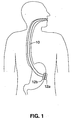
- an access cannula 10 Fig. 1
- Instruments are passed through the cannula and are used to form an incision in the stomach or intestinal wall, giving access to the peritoneal cavity.
- the access cannula 10 is anchored in the incision using expandable anchors 12a, 12b positioned against the inner and outer surfaces of the stomach wall. Insufflation gas may be introduced into the peritoneal cavity via the access cannula to create working space within the cavity.
- the access cannula may include valves or seals that allow for sealed access through the incision, permitting sterile passage of instruments into the peritoneal cavity without loss of insufflation pressure.
- the access cannula 10 may be a flexible tube formed of polymeric material (e.g. polyurethane) having an embedded braid. In other embodiments, a more rigid access cannula may be used.
- the '009 application describes various additional components of access cannula systems, including anchoring features, elements for forming incisions in an interior body wall such as the stomach, and closure devices.
- This application describes a procedural cannula and support system ideally used in combination with an access cannula that has been used to gain access to the peritoneal cavity. For example, once access cannula 10 has been passed through the oral cavity and stomach and secured within a stomach wall incision using anchors 12a, 12b, a procedural cannula and support system of the type described herein is passed through the access cannula and into the peritoneal cavity.
- the disclosed embodiments include at least one procedural or tool cannula through which instruments are passed to the operative site.
- a support system provides rigid support for the procedural cannula(s) within the body.
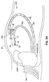
- a natural orifice surgical system includes an instrument system 22 and a support system 24.
- These figures schematically illustrate the peritoneal cavity of a patient with the support system and instrument system extending into the cavity from an incision (not shown) through the stomach wall.
- the support system 24 forms a sort of scaffold within the body to support the instrument system 22 in a location that allows the surgeon to advance the instruments of the instrument system using a desired approach.
- the user might position the support system 24 adjacent the abdominal wall W as shown in Fig. 2A .
- Support system 24 includes an elongate shaft or spine 26 that extends from an incision in a body organ such as the stomach S or other hollow organ (e.g. intestine, vagina) from which natural orifice access has been gained as described above.
- shaft 26 is disposed within an access cannula 10 which may be of the type shown in Fig. 1 .
- Shaft 26 is preferably one capable of being sufficiently flexible for passage through the natural orifice and body organ, and for manipulation within the peritoneal space, but also capable of being placed in a self-supporting rigid state once positioned at a desired location.
- shaft 26 is a shaft formed of a plurality of spine elements 28 having tensioning cables that may be placed under tension to stiffen the shaft 26.
- the spine elements are shaped such that the shaft 26 will assume a shape predetermined to give the curvature needed to position the shaft 26 at the desired location.
- Shaft 26 may include a lumen (not shown) or other features for supporting an endoscope (not shown) oriented towards the treatment site.
- Instrument system 22 includes one or more procedural cannulas 30a, 30b, each having an opening 152 at or near its distal end.
- Cannulas 30a, 30b may include a curved distal portion as shown, and may additionally or alternatively be deflectable in predetermined directions using pullwires, mandrels, or other deflection mechanisms, including those known in the art for deflecting catheters, introducers and guidewires.
- Instruments 32 are extendable through the procedural cannulas 30a, 30b and into position at the target site in the peritoneal cavity.
- two procedural cannulas are useful in that they allow for the simultaneous use of two instruments 32.
- the procedural cannulas 30a, 30b may be passed into the peritoneal cavity via the same access cannula 10 ( Fig. 1 ) through which the support shaft 26 extends, or they may be passed through one or more separately placed access cannulas 10, or, as described in detail in connection with Fig. 3 , they may be passed through a lumen in the shaft 26.
- a coupling 34 couples the instrument system 22 and support system 24.
- the coupling 24 may by any type of device that couples the procedural cannulas 30a, 30b to the shaft 28.
- the coupling takes the form of a linkage 36 that allows the cannulas to be suspended from the shaft 26 and also provides the additional benefit of maintaining the orientation of the cannulas 30a, 30b relative to one another.
- the linkage 36 which is most visible in Fig. 2B , includes a first mount 38 on the shaft 26, and second mounts 40a, 40b on the procedural cannulas 30a, 30b.
- Linkage bars 42a, 42b are pivotally coupled to the mount 38 and the mounts 40a, 40b.
- Second linkage bars 44a, 44b are pivotally coupled to the mounts 40a, 40b and a pivot point 46.
- the support system 24 positions the procedural cannulas 30a, 30b so that access to the treatment site can be gained using an approach that is familiar to the practitioner, despite the fact that the instruments are inserted into the body using a drastically different approach.
- Deflection features of the cannulas 30a, 30b allow those cannulas to be manipulated so as to position the instruments 32 where they are needed, without requiring that the instruments include specialized features for steering and deflection.
- the linkage 36 maintains the relative orientation of the cannulas 30a, 30b towards the treatment site.
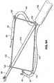
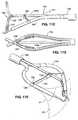
- Fig. 3 shows a second embodiment of a natural orifice surgical system 100.
- System 100 includes a locking spine 102 and a pair of tool cannulas 104.
- the system 100 is similar to the embodiment of Figs. 2A and 2B , but differs in that the tool cannulas 104 pass through a lumen 105 in the shaft of the locking spine 102 of the support system, allowing for a more streamlined system that occupies a reduced amount of space.
- An endoscope 107 also extends through the spine 102, allowing the user to observe the procedure being carried out at the distal end of the system.
- Instruments 32 extend from the tool cannulas to the operative sites. Instruments 32 may include forceps, retractors or any other instruments needed to carry out the desired procedure within the peritoneum.
- the locking spine 102 is preferably passed into the body through an access cannula 10 as described in connection with Fig. 1 and as shown in Figs. 9 and 10 .
- Spine 102 is preferably one capable of being sufficiently flexible for manipulation within the peritoneal space, but also capable of being placed in a self-supporting rigid state once positioned at a desired location.
- spine 102 is a shaft formed of a plurality of spine elements having tensioning cables that may be placed under tension to stiffen the shaft.
- the spine elements are shaped such that the spine will assume a shape predetermined to give the curvature needed to position the distal end of the spine at the desired location and oriented towards the treatment site.
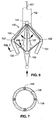
- locking spine 102 is formed of a plurality of spine segments 106a, 106b threaded over a pair of cables (not shown in Fig. 4 ) to form a flexible shaft.
- Each cable is coupled to a locking handle 108 that is moveable to the locked position shown in Fig. 4 to apply tension to the cables and to thereby rigidize the spine 102.
- the handles are moved in the direction of arrows A.
- a plurality of the spine segments 106a are cylindrical segments having end faces that are perpendicular to the axis of the cylindrical segments. When a plurality of these cylindrical segments 106a is strung over the cables, they form a relatively straight spine section 110 when the handles 108 are locked. Others of the spine segments 106b have angular end faces and are assembled such that the chosen combination of angled segments 106b will give the distal portion 112 of the spine 102 a predetermined bend configuration when the spine 102 is locked as shown in Fig. 4 .
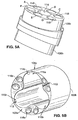
- Fig. 5A is a perspective view showing a pair of angled spine segments 106b assembled together.
- Each spine segment includes a central through hole 114 and a plurality of side through holes 116 surrounding the central through hole 114. Similar hole patterns may also be included in the cylindrical segments 106a that form the straight section of the spine.
- a variety of angled spine segments with end faces of different angles make up the curved distal portion of the spine.
- a group of spine segments with a predetermined combination of angles are selected to produce an overall shape for the spine that will support the associated tools in an optimal position for the procedure to be carried out within the body.
- spine segments are combined to create a inulti-dimensional bend as shown.
- the spine segments 106a, 106b etc. are "strung" onto cables 118 by passing each of the cables through one of the side through holes 116 in each of the spine segments.
- the side hole that is to receive the cable 118 for a particular spine segment 106b is selected based on the orientation in which the angled face of that segment must be placed to give the spine 102 the correct curve at that particular location on the spine 102.
- manufacturing instructions might list out a sequence of angled segments, giving for each segment the face angle that is to be used, as well as a designation of which side holes 116 are to receive each cable for that particular segment.
- An exemplary entry on the list might read "segment #10, angle 15°, cable #1 through hole A, cable #2 through hole D".
- the central through holes 114 of the spine segments 106a, 106b align to form the lumen 105 ( Fig. 4 ) of the spine 102.
- Fig. 5B shows an alternative spine segment 106c having a concave end face 103a and a concave end face 103b, each of which comes together in a nesting relationship with adjacently placed spine segments.
- Slots 113 may be provided the concave face 103a for receiving corresponding mating ribs (not shown) on the convex face, allowing the segments to "key" together when assembled to minimize rotational movement of segments relative to one another.
- the central through hole 114c includes a plurality of lobes 115a, 115b, 115c each sized and positioned such that one or more instruments passed through the through hole 114c can seat in a corresponding one of the lobes. This helps to maintain the instruments in a stable position within the elongate lumen of the spine formed by the assembly of the segments 106c.
- the holes 116c through which the cables (not shown) are threaded are positioned in pairs as shown, although alternate patterns will be equally suitable.
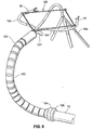
- Fig. 6 is a perspective view of the distal end of the system 100 of Fig. 3 , showing the distal ends of the tool cannulas 104.
- the system 100 includes features that work in combination with the spine 102 to support and orient the tool cannulas 104 as appropriate for a given procedure.
- a linkage 120 is pivotally connected to the cannulas 104 at pivot points 122 and couples the cannulas 104 to the supporting spine 102.
- Linkage 120 also provides structural support for the distal portions of the tool cannulas 104 and maintains the relative orientation of the cannulas 104.
- the linkage 120 is attached to a pivot mount 124 on the distal portion of the locking spine 102.
- Another of the pivot mounts 125 is coupled to a pull wire 127 that extends proximally through spine 102 to a location outside the body.
- pivot mount 125 may be coupled to the distal portion of a third longitudinal tool cannula 104a extending longitudinally from the spine 102, or to a similarly positioned tool shaft.
- either or both of the pivot mounts 124, 125 may extend into free space as shown in Figs. 9 and 10 instead of being attached to the cannula 104a and/or spine 102.
- the linkage 120 is positionable in a collapsed streamlined position in which tool cannulas 104 are near the longitudinal axis of the spine 102 for passage through the access cannula 10.
- Dashed lines in Fig. 6 show the arrangement of the linkage 120 and pivot mounts 122 when in the collapsed position.
- the pivot mounts 122 When in the streamlined position, the pivot mounts 122 are positioned side by side, thus orienting the tool cannulas 104 adjacent to one another.
- the pivot mounts are positioned approximately 3 - 7 inches apart, and more preferably approximately 4-6 inches apart.
- Opening the linkage positions the cannulas 104 as shown in Figs. 3, 6 and 8A-10 and thus points the instruments 32 positioned in the cannulas 104 generally towards an operative site.
- the linkage 120 of Fig. 6 may be deployed to the open position by withdrawing pull wire 127
- the Fig. 8A , 8B embodiment can be deployed by advancing the distal end of the longitudinal tool cannula 104a in a distal direction to move the linkage 102 out of the access cannula and/or to deploy the linkage to the expanded position.
- one or more of the pivot points 122, 124, 125 may be spring loaded to facilitate expansion of the linkage 120. Any combination of these deployment mechanisms, or others not specifically mentioned, may instead be used to deploy the linkage 120 in the peritoneal cavity.
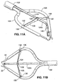
- linkage 120a includes a pair of members 130.
- Each member 130 is attached by a corresponding one of the tool cannulas 104 by a first hinge 132 and to a central retractor 104b (or, alternatively, to a longitudinal tool cannula like cannula 104a of Fig. 8A ) by a second hinge 134.
- Hinges 132 may be mounted to corresponding collars 136 on the tool cannulas 104, and hinge 134 may be on a similar collar 138 ( Fig. 11B ) on retractor 104b.
- members 130 When linkage 120a is in the collapsed position, members 130 extend in a distal direction as shown in Fig. 11D .
- central retractor 104b is withdrawn proximally, causing the members 130 to pivot at hinges 132, 134.
- central retractor 104b includes a proximal section 140 and a distal section 142.
- Proximal section 140 is formed of a number of segments 144 strung onto one or more cables, with shorter segments 146 and an instrument tip 147 on the distal section 142.
- Cables within the retractor 104b are arranged such that the retractor becomes rigid when the cables are tensioned, and such that distal section 142 will deflect when the balance of tension within the cables is altered using controls outside the body.
- retractor 104b may be deflectable towards and away from the body tissue as shown in Fig. 11C to allow tissue to be lifted by the retractor so the tissue may be acted upon by an instrument carried by one of the tool cannulas 104.
- Additional pull cables (not shown) are operable to open and close the jaws of the retractor tip 147.
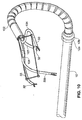
- each tool cannula 104 preferably has a pre-shaped curve in its distal region.
- the curve orients the cannula 104 such that when the linkage is opened, instruments 32 (Figs. 10A, 10B) passed through the central lumens 126 of the cannulas 104 can access a common treatment site.
- the preformed shape may be set using any of a number of methods.
- the shaped region may have a segmented construction similar to the segmented spine 102, with the individual segments shaped to give the tool cannulas a shape that will orient the cannulas as shown in Figs, 3 , 9 and 10 when the cables running through the segments are tensioned.
- the entire length of the cannula may be segmented, or the distal portion may be formed of polymer tubing to allow flexibility.
- cannulas 104 can be made of pre-curved tubing having rigidity sufficient to prevent buckling during use. Reinforcing braid made of stainless steel or other materials may be formed into the walls of the tubing in the rigid section of the cannulas 104.
- each tool cannula 104 further includes a region that is deflectable in multiple directions to allow positioning and manipulation of the operative ends of the instruments: This avoids the need for sophisticated steerable surgical instruments. Instead, instruments 32 ( Fig. 10 ) having flexible shafts are positioned in the tool cannulas 104, and steering of the instruments is achieved by deflecting the tool cannulas 104. Because the tools 32 are flexible, it may be necessary to "stiffen" the shaft of the tool 32 to allow the tool to be successfully used.
- a slideable stiffening cannula 33 ( Fig.
- the tool 10 may be advanced from within the tool cannula 104 over a portion of the shaft of the tool 32 to effectively stiffen the tool's shaft during the procedure, thus allowing the tool to be pressed into contact with body tissue without buckling.
- Other internal structures such as stiffening mandrels, reinforcing collars or braids, may instead be used for this purpose.
- deflection of the tool cannulas 104 is performed using a pullwire system.
- pullwires 128 extend through corresponding pullwire lumens 130, preferably spaced at intervals of 90°.
- the distal ends of the pullwires are anchored in the distal sections of the cannula 104 such that the distal section of the cannula can be made to deflect in a desired direction by pulling on the desired combination of pullwires.
- Fig. 11E illustrates in dashed lines V1 a conical volumes defined by an exemplary movement pattern for the tool cannula 104, and the corresponding volume V2 defined by the tool 32 within the cannula 104.
- Actuation of the pullwires is achieved using features that during use are positioned outside the body.
- a deflection system is provided that allows the user to intuitively actuate the pullwires for a particular one of the tool cannulas 104 by manipulating the handle 152 of the instrument 32 that resides within that tool cannula. For example, if the user wishes to have the distal end of a tool move in a downward direction, s/he will intuitively raise the handle 152 of that tool to cause the corresponding tool cannula to deflect downwardly, thus moving the tool to the desired position.
- the proximal ends of the pullwires 128 extend from the proximal ends of the cannulas 104 and feed into a corresponding deflection system, which in the illustrated embodiments is a control gimbal 148.
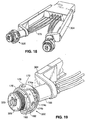
- the gimbal 148 many be mounted to a work stand 150 as shown in Fig. 12A .
- the work stand 150 may be set on top of the patient's torso or mounted to supports coupled to one or both side-rails of the surgical table, or carried on a cart. In either case, the work stand 150 is positioned to give the surgeon convenient and intuitive access to the handles 152 while s/he observes the procedure on an endoscopic display (not shown). As shown in Fig.
- use of the system may be facilitated by providing a "cockpit" for the user, coupling an endoscopic display 154 to the work stand 150 that supports the control gimbals 148, as well as the proximal controls for the endoscope 107, and other ports 111 for passing instruments through the access cannula to the peritoneal space.
- the work stand 150 is proportioned to allow the surgeon to position his or herself in a comfortable position with his/her hands on the handles 153 of the tools 32.
- the work stand 150 preferably positions the tool handles 153 approximately 10 - 15 inches apart.
- a preferred control gimbal 148 is shown in Fig. 13 . It includes a base 168 mounted to the work stand (not shown in Fig. 7 ) and having a tubular channel 170.
- a c-shaped mount 172 is connected to the base 168 and includes a through hole 174 continuous with the lumen of the tubular end piece 170. In a slight modification, the hole 174 might be accompanied by four separate through holes 174a-d might be used for receiving pull wires as in the Fig. 19 embodiment.
- a ring 176 is pivotally mounted to the mount 172 at pivot bearings 178.
- a semi-spherical ball 180 is pivotally mounted within the ring at pivots 182.
- Four pull-wire ports 184 extend from the interior of the ball 180 to its outer surface.
- Instrument port 186 includes side channels 190 having distal openings 192 and proximal openings 194.
- the four pullwires 128 from the tool cannulas 104 extend through the tubular end piece 170 and each passes through hole 174, through the hollow interior of the ball 180, and out corresponding ones of the pull-wire ports 184 in the ball.
- the pullwires further extend into the instrument port side channels 190 and are secured there by anchors 196.
- Instrument port 186 has a lumen 188 extending proximally from the spherical ball 180.
- the shaft 152 of an instrument 32 extends through the lumen 188 and the ball 180, through hole 174 in the c-shaped mount 172, and via tube 170 and the work stand 150 ( Fig. 12A ), into the corresponding tool cannula 104.
- the operative end of the instrument 32 extends from the distal end of the tool cannula 104.
- the control gimbal allows combinations of vertical and lateral deflection, giving 360° deflection as shown in Fig. 11E .
- user may additionally advance/retract the tool 32 longitudinally within the tool cannula 104, and/or axially rotate the tool 32 relative to the tool cannula when required.
- the control gimbal 148 includes a locking mechanism that allows an instrument orientation to be temporarily fixed until further deflection is needed. This feature allows a user to fix a trajectory for multiple instruments that are to be sequentially used at a particular location. For example, once the orientation of a tool cannula 104 is set, a certain step in the procedure may be performed using a first instrument passed through that cannula. When a subsequent step requiring a different instrument is to be performed, the instruments are exchanged without moving the tool cannula 104. This allows the second instrument to be advanced to the exact location at which it is needed without additional steering.
- One exemplary locking mechanism includes a pair of locking screws 198 that are tightened as shown by arrows in Fig. 15A to lock the C-mount 172 to the ring 176 and to lock the ring 176 and the ball 180.
- a simple pneumatic shaft lock 200 could be employed on each of the gimbal's pivot axes.
- a solenoid or similar device might be used in place of the pneumatic lock 200.
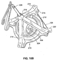
- FIGs.16A and 16B An alternate gimbal arrangement is shown in Figs.16A and 16B .
- a cone shaped instrument port 202 is mounted to the proximal end of each cannula, and includes a diaphragm seal 204 having a slit 206 sealable around an instrument shaft 208 passed into the instrument port 202.
- a diaphragm seal 204 having a slit 206 sealable around an instrument shaft 208 passed into the instrument port 202.
- Figs. 16A and 16B only the handle of instrument shaft 208 is shown to permit easier viewing of the surrounding features.
- a gimbal 210 includes a collar 212 mounted on the instrument port 202 and four wings 214 radiating from the collar 212. Each pullwire 128 is coupled to one of the wings 214. Struts 216 extend proximally from the wings 214 and are joined to a sleeve 218 through which a portion of the instrument shaft 208 extends. Collar 212 is moveable relative to the instrument port 202, and in particular collar 212 is rotatable about its central axis, and pivotable in multiple directions. Movement of the collar 212 places one or more of the pullwires 128 under tension and results in deflection of the cannula 104.
- instrument shaft 208 is coupled to the collar 212 by struts 216, a user can manipulate the instrument shaft 208 handle in an intuitive manner similar to a joystick to allow the user to steer the distal end of the cannula 104 in the desired direction.
- Fig. 17 illustrates an alternative natural orifice surgical system 300.
- System 300 includes features that are largely similar to those described elsewhere.
- the system 300 uses the linkage 120a of Fig. 11A , and a gimbal system similar to that described in connection with Fig. 13 .
- the system 300 differs from the earlier embodiments in that it allows a user to adjust the sensitivity of the gimbals.
- the gimbal can be fine tuned such that the amount of deflection of the tool cannulas corresponds directly to the amount by which the user moves the tool handles 152 within the gimbal system, or the amount of deflection can be greater than or less than the corresponding movement of the tool handles.
- gimbal 302 many of the features of the gimbal 302 are similar to those of gimbal 148 of Figs. 12 and 13 . These similar features include base 168, which is coupled to frame 304.
- Four through-holes 174a-d (three of which are visible in Fig. 19 ), one for each pull wire, extend from c-shaped mount 172 through base 168.
- the pullwires feed into the through-holes 174a-d from cable housings 175 that pass through the frame 304.
- the more distal segments of the pullwires extend from the from the frame 304 into the tool cannulas 104 extending distally from the frame 304.
- a ring 176 is pivotally mounted to mount 172 at pivots 178, and semi-spherical ball 180 is pivotally mounted within the ring 176 at pivots 182.
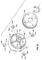
- the gimbal 302 of Fig. 19 differs from the gimbal 148 of Figs. 12-13 in its inclusion of a microadjustment assembly 306.
- the four pullwires of one of the tool cannulas terminate in the gimbal at 90 degree quadrants.
- Motion of the instrument shaft 152 ( Fig. 17 ) alters the tension on the various pullwires, which causes deflection of the tool cannula tip and corresponding movement of the tool within the tool cannula.
- the effect lever arm of each pull wire is altered in the Fig. 19 embodiment by moving the point of termination of each pull wire towards or away from the gimbal's center of rotation. Moving the pullwire terminations away from the center of rotation causes movement of the tool cannula 104 to be amplified relative to the movement of the tool handle 152, whereas moving the pullwire terminations towards the center of rotation decreases the amplification.
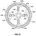
- Ball 180 includes a distal surface 314 as shown in Fig. 21A, and a planar proximal surface 316 as shown in Fig. 20 .
- Four radial slots 318a-d extend through between the surfaces 314, 316.
- four sliding terminal plates 308a-d each including a pullwire terminal 310a-d and a proximally-extending follower pin 312a-d, are positioned in contact with the planar proximal surface 316.
- a peg 317 on the distal side of each terminal plate is received in the corresponding one of the slots 318a-d.
- Each pullwire used to deflect the tool cannula extends through one of the slots 318a-d and is anchored within a terminal 310a-d of one of the four sliding terminals 308a-d.
- Fig. 21A shows the distal facing side 314 of the ball 180, with the terminals 310a-d positioned over the slots 318a-d. The pull wires themselves are not shown.
- a tubular instrument port 320 is centrally positioned on the proximal surface 316 of the ball 180.
- a retainer cap 322 covers the surface 316, such that the instrument port 320 extends through a central opening 324 in the retainer cap.
- the sliding terminal plates 308a-d are sandwiched between the surface 316 and the retainer cap 322.
- Fig. 22 shows the cap 322 removed from the ball 180.
- the inner, distal facing, surface of the cap 322 includes a spiral rib 326 defining a spiral shaped slot 328.
- Each of the follower pins 312a-d of the terminal plates 308a-d are disposed within the spiral slot 328.
- a retaining ring 330 is engaged with the instrument port 320 and functions to hold the cap 322, terminal plates 308a-d, and ball 180 together such that the follower pins 312a-d remain within the spiral slot 328.
- Cap is rotatable in clockwise and counterclockwise directions relative to the instrument port 320. Rotation of the cap will increase or decrease the sensitivity of the gimbal system. More specifically, if the cap is rotated in a first direction, the spiral rib 326 will cause the pins 312a-d to advance through the spiral slot towards the outer circumference of the cap, causing the terminal plates to slide radially outwardly within slots, thereby increasing the sensitivity of the gimbal system.
- the pins will advance through the spiral slot toward the center of the cap, causing the terminal plates to slide radially inwardly within the slots so as to loosen the tension on the pullwires and to decrease the sensitivity of the gimbal system.
- Markings 328 on the cap 322 and a corresponding pointer 330 instruct the user as to the level of sensitivity achieved when the cap is in one of the designated rotational positions relative to the pointer 330.
- the user may have the option to set different sensitivity levels for different ones of the pull wires.
- the system is preferably packed in a kit containing instructions for use instructing the user to use the system in the manner disclosed herein.
- the methods of use described herein not form part of the invention and are provided for illustrative purposes only.
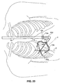
- Fig. 23 schematically illustrates use of the system of Figs. 9 and 10 as used such as for a cholecystectomy procedure.
- the access cannula 10 is placed transorally and moved into the peritoneal cavity via a left anterior stomach wall puncture.
- the access cannula 10 is anchored in a stomach incision as described above.
- the locking spine 102 is introduced into the peritoneal space and made rigid (via application of tension on the cables as described above) such that it is oriented towards the procedural site as shown.
- the liver retractor 35a is used to lift and retract the liver superiorly away from the gallbladder and the operational area of the instruments 32. Instruments 32 are advanced through the tool cannulas and used to perform the procedure.
- Tool cannulas 104 are deflected as needed to manipulate the instruments.
- prior art laparoscopic procedures involve formation of three surgical ports or incision X (tool port), Y (endoscope port), Z (tool port) to perform the cholecystectomy procedure
- use of the disclosed system allows the procedure to be performed less invasively while allowing the surgeon to carry out the procedure from the same familiar perspective from which s/he would have performed the laparoscopic procedure.
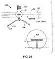
- a system 400 may be attached to the interior of the abdominal wall using a screw 402, t-bar 404, inflatable balloon anchor, expandable braid, or similar device embedded in the facial layer of the stomach wall W.
- the system 400 includes features that support a procedural cannula 406 introduced into the peritoneal space via a natural orifice as described above.
- the procedural cannula 406 is passed through or engaged with a guide ring 408 that helps to orient the distal end 410 of the procedural cannula 406, and thus tools 412 passed through the procedural cannula 406, towards the treatment site.
- the system may use magnetism to support, retain and/or locate tools at the desired vantage point, such as near the inside of the abdominal wall.
- This embodiment might use cannulas having magnetic features within the body, and an external electromagnetic outside the body.
- the embodiment might employ a steel/iron plate outside the body and magnetic cannulas that are attracted to the steel/iron plate.
Claims (11)
- Chirurgisches System (100), das Folgendes aufweist:einen länglichen Träger (102), der zum Einführen in eine Körperhöhle proportioniert ist;wenigstens zwei Instrumente (32), die jeweils einen flexiblen Schaft haben;wenigstens zwei Instrumentenkanülen (104), die von dem länglichen Träger getragen werden, wobei jede Instrumentenkanüle einen ablenkbaren distalen Teil und ein Lumen (126) zum entfernbaren Aufnehmen eines Instruments zum Durchführen eines Verfahrens innerhalb der Körperhöhle hat, wobei die ablenkbaren distalen Teile eine stromlinienförmige Stellung zur Einführung in eine Körperhöhle und eine abgelenkte Stellung haben, die die Lumen positioniert, um den Instrumenten Zugang zu einem gemeinsamen Operationsfeld zu gewähren;wobei jede Instrumentenkanüle mehrere Zugdrähte (128) hat, so dass ihr ablenkbarer distaler Teil als Reaktion auf die Anwendung von Spannung auf wenigstens einen der Zugdrähte ablenkbar ist, um dadurch ein in dem Lumen der Kanüle positioniertes Instrument zu lenken; undein Paar gleitfähiger Versteifungskanülen (33), die jeweils von einer entsprechenden der Instrumentenkanülen über einen Teil des Schafts des entsprechenden Instruments vorbewegbar ist.
- System nach Anspruch 1, wobei der längliche Träger ein segmentiertes Rückgrat beinhaltet, das von mehreren durch ein Kabel (118) gekoppelten Rückgratelementen (106a, 106b, 106c) gebildet wird, wobei der Träger bei Anwendung von Spannung auf das Kabel von einer flexiblen auf eine starre Stellung bewegbar ist.
- System nach Anspruch 1, wobei der längliche Träger ein Lumen (105) beinhaltet und wobei die Instrumentenkanüle durch das Lumen verläuft.
- System nach Anspruch 1, wobei die Zugdrähte proximale Enden beinhalten, die mit einem Kardanelement (148) verbunden sind, wobei das Kardanelement in mehrere Richtungen bewegbar ist, um Spannung auf die Zugdrähte auszuüben.
- System nach Anspruch 4, wobei das Kardanelement eine Instrumentenöffnung mit einem Durchlass beinhaltet, wobei das Kardanelement durch Bewegung der Instrumentenöffnung bewegbar ist und wobei die Instrumentenöffnung proportioniert ist, um ein distales Ende eines Instruments beim Vorbewegen des distalen Endes des Instruments in die Instrumentenkanüle hinein aufzunehmen.
- System nach Anspruch 5, wobei die Instrumentenöffnung durch die Bewegung eines Griffs eines in der Instrumentenöffnung positionierten Instruments bewegbar ist.
- System nach Anspruch 1, das ferner einen von dem länglichen Träger getragenen aufspreizbaren Rahmen (120) aufweist, wobei der Rahmen auf eine aufgespreizte Stellung aufspreizbar ist, um die ablenkbaren distalen Teile in ihren aufgespreizten Stellungen zu positionieren, wobei der Rahmen wenigstens zwei Rahmenelemente (130) beinhaltet, wobei jedes Rahmenelement schwenkbar mit einer Instrumentenkanüle gekoppelt ist.
- System nach Anspruch 7, das ferner eine in eine natürliche Öffnung einführbare Zugangskanüle (10) und einen Anker beinhaltet, der mit der Zugangskanüle gekoppelt ist und zum Festhalten der Zugangskanüle in einem in einer Wand eines inneren Körperorgans gebildeten Einschnitt aufspreizbar ist, wobei die Zugangskanüle ein Lumen hat, wobei der längliche Träger, der Rahmen und die Instrumentenkanülen durch das Lumen der Zugangskanüle einführbar sind, wenn der Rahmen in einer zusammengefalteten Stellung ist.
- System nach Anspruch 1, wobei das System ferner eine Halterung und ein Paar Stellglieder an der Halterung beinhaltet, wobei die Zugdrähte jeder Instrumentenkanüle mit einem der Stellglieder gekoppelt sind.
- System nach Anspruch 9, wobei jedes Stellglied eine Instrumentenöffnung beinhaltet, so dass sich ein in einer der Instrumentenkanülen positioniertes Instrument durch eine entsprechende der Instrumentenöffnungen erstreckt, und wobei die Bewegung eines Griffs (153) eines Instruments in der Instrumentenöffnung die Zugdrähte betätigt.
- System nach Anspruch 9, wobei die Halterung an einem Operationstisch anbringbar ist.
Applications Claiming Priority (5)
| Application Number | Priority Date | Filing Date | Title |
|---|---|---|---|
| US79456306P | 2006-04-24 | 2006-04-24 | |
| US80111306P | 2006-05-17 | 2006-05-17 | |
| US80103406P | 2006-05-17 | 2006-05-17 | |
| US81923506P | 2006-07-07 | 2006-07-07 | |
| PCT/US2007/009936 WO2007127199A1 (en) | 2006-04-24 | 2007-04-24 | Natural orifice surgical system |
Publications (2)
| Publication Number | Publication Date |
|---|---|
| EP2012650A1 EP2012650A1 (de) | 2009-01-14 |
| EP2012650B1 true EP2012650B1 (de) | 2016-07-27 |
Family
ID=38515465
Family Applications (1)
| Application Number | Title | Priority Date | Filing Date |
|---|---|---|---|
| EP07755964.9A Active EP2012650B1 (de) | 2006-04-24 | 2007-04-24 | Chirurgisches system für natürliche öffnungen |
Country Status (6)
| Country | Link |
|---|---|
| US (2) | US7833156B2 (de) |
| EP (1) | EP2012650B1 (de) |
| JP (2) | JP5091229B2 (de) |
| AU (1) | AU2007243484B2 (de) |
| CA (1) | CA2650474A1 (de) |
| WO (1) | WO2007127199A1 (de) |
Families Citing this family (168)
| Publication number | Priority date | Publication date | Assignee | Title |
|---|---|---|---|---|
| US7951117B2 (en) * | 2008-06-25 | 2011-05-31 | Tyco Healthcare Group Lp | Multi-lumen access port |
| JP4690399B2 (ja) * | 2005-05-26 | 2011-06-01 | 株式会社アルス | 内視鏡装置 |
| US9289112B2 (en) * | 2006-01-13 | 2016-03-22 | Olympus Corporation | Medical treatment endoscope having an operation stick formed to allow a procedure instrument to pass |
| US8556805B2 (en) | 2006-01-13 | 2013-10-15 | Olympus Medical Systems Corp. | Rotational force transmission mechanism, force-attenuating apparatus, medical device, and medical instrument-operation mechanism |
| US8617054B2 (en) * | 2006-01-13 | 2013-12-31 | Olympus Medical Systems Corp. | Medical treatment endoscope |
| US8439828B2 (en) | 2006-01-13 | 2013-05-14 | Olympus Medical Systems Corp. | Treatment endoscope |
| US9173550B2 (en) | 2006-01-13 | 2015-11-03 | Olympus Corporation | Medical apparatus |
| US9308049B2 (en) * | 2006-01-13 | 2016-04-12 | Olympus Corporation | Medical treatment endoscope |
| US8021293B2 (en) * | 2006-01-13 | 2011-09-20 | Olympus Medical Systems Corp. | Medical treatment endoscope |
| ITMI20060443A1 (it) * | 2006-03-13 | 2007-09-14 | Ethicon Endo Surgery Inc | Dispositivo per la manipolazione di tessuto corporeo |
| US8518024B2 (en) | 2006-04-24 | 2013-08-27 | Transenterix, Inc. | System and method for multi-instrument surgical access using a single access port |
| EP2023793B1 (de) * | 2006-05-17 | 2015-11-18 | TransEnterix, Inc. | Einzelner zugang für mehrere chirurgische instrumente |
| US9345387B2 (en) * | 2006-06-13 | 2016-05-24 | Intuitive Surgical Operations, Inc. | Preventing instrument/tissue collisions |
| JP5466004B2 (ja) | 2006-06-22 | 2014-04-09 | ボード オブ リージェンツ オブ ザ ユニバーシティ オブ ネブラスカ | 磁気的連結可能ロボット装置および関連する方法 |
| US9579088B2 (en) * | 2007-02-20 | 2017-02-28 | Board Of Regents Of The University Of Nebraska | Methods, systems, and devices for surgical visualization and device manipulation |
| US8679096B2 (en) | 2007-06-21 | 2014-03-25 | Board Of Regents Of The University Of Nebraska | Multifunctional operational component for robotic devices |
| US10008017B2 (en) | 2006-06-29 | 2018-06-26 | Intuitive Surgical Operations, Inc. | Rendering tool information as graphic overlays on displayed images of tools |
| US9718190B2 (en) | 2006-06-29 | 2017-08-01 | Intuitive Surgical Operations, Inc. | Tool position and identification indicator displayed in a boundary area of a computer display screen |
| US7866525B2 (en) * | 2006-10-06 | 2011-01-11 | Tyco Healthcare Group Lp | Surgical instrument having a plastic surface |
| US9421071B2 (en) | 2006-12-01 | 2016-08-23 | Boston Scientific Scimed, Inc. | Direct drive methods |
| US7655004B2 (en) | 2007-02-15 | 2010-02-02 | Ethicon Endo-Surgery, Inc. | Electroporation ablation apparatus, system, and method |
| US8100930B2 (en) * | 2007-03-30 | 2012-01-24 | Ethicon Endo-Surgery, Inc. | Tissue moving surgical device |
| US8142356B2 (en) * | 2007-03-30 | 2012-03-27 | Ethicon Endo-Surgery, Inc. | Method of manipulating tissue |
| JP2008284107A (ja) * | 2007-05-16 | 2008-11-27 | Olympus Corp | 体腔内挿入具案内器具及び体腔内挿入具案内システム |
| EP2343024B1 (de) | 2007-05-18 | 2018-05-02 | Boston Scientific Scimed, Inc. | Antriebssysteme |
| US9469034B2 (en) * | 2007-06-13 | 2016-10-18 | Intuitive Surgical Operations, Inc. | Method and system for switching modes of a robotic system |
| EP2170564A4 (de) | 2007-07-12 | 2015-10-07 | Univ Nebraska | Betätigungsverfahren und -systeme in robotergeräten |
| US8157727B2 (en) * | 2007-07-16 | 2012-04-17 | Ethicon Endo-Surgery, Inc. | Surgical methods and devices with movement assistance |
| EP2178431A4 (de) | 2007-08-15 | 2017-01-18 | Board of Regents of the University of Nebraska | Medizinische inflations-, aufbringungs- und verabreichungsvorrichtungen sowie entsprechende verfahren |
| US8579897B2 (en) | 2007-11-21 | 2013-11-12 | Ethicon Endo-Surgery, Inc. | Bipolar forceps |
| US20090227843A1 (en) * | 2007-09-12 | 2009-09-10 | Smith Jeffrey A | Multi-instrument access devices and systems |
| US20110060183A1 (en) * | 2007-09-12 | 2011-03-10 | Salvatore Castro | Multi-instrument access devices and systems |
| US20090112059A1 (en) | 2007-10-31 | 2009-04-30 | Nobis Rudolph H | Apparatus and methods for closing a gastrotomy |
| US8540744B2 (en) * | 2008-04-01 | 2013-09-24 | Ethicon Endo-Surgery, Inc. | Tissue penetrating surgical device |
| US20090287045A1 (en) | 2008-05-15 | 2009-11-19 | Vladimir Mitelberg | Access Systems and Methods of Intra-Abdominal Surgery |
| US8771260B2 (en) | 2008-05-30 | 2014-07-08 | Ethicon Endo-Surgery, Inc. | Actuating and articulating surgical device |
| US8906035B2 (en) | 2008-06-04 | 2014-12-09 | Ethicon Endo-Surgery, Inc. | Endoscopic drop off bag |
| US8888792B2 (en) | 2008-07-14 | 2014-11-18 | Ethicon Endo-Surgery, Inc. | Tissue apposition clip application devices and methods |
| US8834353B2 (en) * | 2008-09-02 | 2014-09-16 | Olympus Medical Systems Corp. | Medical manipulator, treatment system, and treatment method |
| US8529435B2 (en) * | 2008-09-26 | 2013-09-10 | Ethicon Endo-Surgery, Inc. | Magnetic scope manipulator |
| WO2010042611A1 (en) * | 2008-10-07 | 2010-04-15 | The Trustees Of Columbia University In The City Of New York | Systems, devices, and method for providing insertable robotic sensory and manipulation platforms for single port surgery |
| US8157834B2 (en) | 2008-11-25 | 2012-04-17 | Ethicon Endo-Surgery, Inc. | Rotational coupling device for surgical instrument with flexible actuators |
| DE102008060418A1 (de) * | 2008-12-05 | 2010-06-10 | Olympus Winter & Ibe Gmbh | Laparoskopisches Instrument mit langgestrecktem Schaft |
| US20110230723A1 (en) * | 2008-12-29 | 2011-09-22 | Salvatore Castro | Active Instrument Port System for Minimally-Invasive Surgical Procedures |
| US8361066B2 (en) | 2009-01-12 | 2013-01-29 | Ethicon Endo-Surgery, Inc. | Electrical ablation devices |
| US20100191050A1 (en) * | 2009-01-23 | 2010-07-29 | Ethicon Endo-Surgery, Inc. | Variable length accessory for guiding a flexible endoscopic tool |
| US9278019B2 (en) | 2009-04-03 | 2016-03-08 | Metamodix, Inc | Anchors and methods for intestinal bypass sleeves |
| US9173760B2 (en) | 2009-04-03 | 2015-11-03 | Metamodix, Inc. | Delivery devices and methods for gastrointestinal implants |
| ES2503553T3 (es) | 2009-04-03 | 2014-10-07 | Metamodix, Inc. | Prótesis gastrointestinales modulares |
| US8702641B2 (en) | 2009-04-03 | 2014-04-22 | Metamodix, Inc. | Gastrointestinal prostheses having partial bypass configurations |
| US8282598B2 (en) * | 2009-07-10 | 2012-10-09 | Metamodix, Inc. | External anchoring configurations for modular gastrointestinal prostheses |
| JP5730873B2 (ja) * | 2009-07-29 | 2015-06-10 | トランセンテリクス・サージカル、インク | 偏向可能な処置器具用ポート部 |
| US8545515B2 (en) * | 2009-09-23 | 2013-10-01 | Intuitive Surgical Operations, Inc. | Curved cannula surgical system |
| US20110071541A1 (en) * | 2009-09-23 | 2011-03-24 | Intuitive Surgical, Inc. | Curved cannula |
| US8623028B2 (en) | 2009-09-23 | 2014-01-07 | Intuitive Surgical Operations, Inc. | Surgical port feature |
| US8888789B2 (en) * | 2009-09-23 | 2014-11-18 | Intuitive Surgical Operations, Inc. | Curved cannula surgical system control |
| US8465476B2 (en) * | 2009-09-23 | 2013-06-18 | Intuitive Surgical Operations, Inc. | Cannula mounting fixture |
| US9474540B2 (en) | 2009-10-08 | 2016-10-25 | Ethicon-Endo-Surgery, Inc. | Laparoscopic device with compound angulation |
| US20110098704A1 (en) | 2009-10-28 | 2011-04-28 | Ethicon Endo-Surgery, Inc. | Electrical ablation devices |
| US8608652B2 (en) | 2009-11-05 | 2013-12-17 | Ethicon Endo-Surgery, Inc. | Vaginal entry surgical devices, kit, system, and method |
| US20110112434A1 (en) * | 2009-11-06 | 2011-05-12 | Ethicon Endo-Surgery, Inc. | Kits and procedures for natural orifice translumenal endoscopic surgery |
| US20110118551A1 (en) * | 2009-11-14 | 2011-05-19 | SPI Surgical, Inc. | Collateral soft tissue protection surgical device |
| US9775640B2 (en) * | 2009-11-14 | 2017-10-03 | SPI Surgical, Inc. | Surgical device |
| US9011326B2 (en) | 2009-11-14 | 2015-04-21 | Spiway Llc | Soft tissue shield for trans-orbital surgery |
| US8986201B2 (en) | 2009-11-14 | 2015-03-24 | Spiway Llc | Surgical tissue protection sheath |
| US9451981B2 (en) | 2009-11-14 | 2016-09-27 | Spiway Llc | Surgical tissue protection sheath |
| US20110152878A1 (en) * | 2009-12-17 | 2011-06-23 | Ethicon Endo-Surgery, Inc. | Interface systems for aiding clinicians in controlling and manipulating at least one endoscopic surgical instrument and a cable controlled guide tube system |
| US9028483B2 (en) | 2009-12-18 | 2015-05-12 | Ethicon Endo-Surgery, Inc. | Surgical instrument comprising an electrode |
| US9005198B2 (en) | 2010-01-29 | 2015-04-14 | Ethicon Endo-Surgery, Inc. | Surgical instrument comprising an electrode |
| US8343045B2 (en) | 2010-04-05 | 2013-01-01 | Intuitive Surgical Operations, Inc. | Curved cannula |
| US20130281924A1 (en) * | 2010-04-13 | 2013-10-24 | Transenterix, Inc. | Segmented instrument shaft with antirotation features |
| US8419767B2 (en) * | 2010-05-04 | 2013-04-16 | Mustafa H. Al-Qbandi | Steerable atrial septal occluder implantation device with flexible neck |
| US8562592B2 (en) * | 2010-05-07 | 2013-10-22 | Ethicon Endo-Surgery, Inc. | Compound angle laparoscopic methods and devices |
| EP2627278B1 (de) | 2010-10-11 | 2015-03-25 | Ecole Polytechnique Fédérale de Lausanne (EPFL) | Mechanischer manipulator für chirurgische instrumente |
| EP2640302B1 (de) * | 2010-11-17 | 2017-12-20 | Boston Scientific Scimed, Inc. | Lageranordnung für ein instrument |
| US10092291B2 (en) | 2011-01-25 | 2018-10-09 | Ethicon Endo-Surgery, Inc. | Surgical instrument with selectively rigidizable features |
| US8840638B2 (en) * | 2011-02-10 | 2014-09-23 | Danny A. Sherwinter | Laparoscopic retractor |
| US9314620B2 (en) | 2011-02-28 | 2016-04-19 | Ethicon Endo-Surgery, Inc. | Electrical ablation devices and methods |
| US9233241B2 (en) | 2011-02-28 | 2016-01-12 | Ethicon Endo-Surgery, Inc. | Electrical ablation devices and methods |
| US9254169B2 (en) | 2011-02-28 | 2016-02-09 | Ethicon Endo-Surgery, Inc. | Electrical ablation devices and methods |
| US9049987B2 (en) | 2011-03-17 | 2015-06-09 | Ethicon Endo-Surgery, Inc. | Hand held surgical device for manipulating an internal magnet assembly within a patient |
| US9259240B2 (en) | 2011-03-29 | 2016-02-16 | Covidien Lp | Articulating surgical access system for laparoscopic surgery |
| EP4275634A3 (de) | 2011-06-10 | 2024-01-10 | Board of Regents of the University of Nebraska | Verfahren, systeme und vorrichtungen in zusammenhang mit chirurgischen endeffektoren |
| CA3082073C (en) | 2011-07-11 | 2023-07-25 | Board Of Regents Of The University Of Nebraska | Robotic surgical devices, systems, and related methods |
| JP5715304B2 (ja) | 2011-07-27 | 2015-05-07 | エコール ポリテクニーク フェデラル デ ローザンヌ (イーピーエフエル) | 遠隔操作のための機械的遠隔操作装置 |
| EP3372143B1 (de) * | 2011-10-21 | 2020-09-02 | Viking Systems, Inc. | Elektronisches lenkbares stereoskopisches endoskop |
| JP6377530B2 (ja) | 2012-01-10 | 2018-08-22 | ボード オブ リージェンツ オブ ザ ユニバーシティ オブ ネブラスカ | 外科的挿入装置 |
| JP6202759B2 (ja) * | 2012-02-02 | 2017-09-27 | トランセンテリクス・サージカル、インク | 機械化された複数の処置器具による手術システム |
| EP3845190B1 (de) | 2012-05-01 | 2023-07-12 | Board of Regents of the University of Nebraska | Robotische einzelstandortvorrichtung sowie entsprechende systeme |
| US9427255B2 (en) | 2012-05-14 | 2016-08-30 | Ethicon Endo-Surgery, Inc. | Apparatus for introducing a steerable camera assembly into a patient |
| EP3680071B1 (de) | 2012-06-22 | 2021-09-01 | Board of Regents of the University of Nebraska | Robotische chirurgische vorrichtungen mit lokaler steuerung |
| US9078662B2 (en) | 2012-07-03 | 2015-07-14 | Ethicon Endo-Surgery, Inc. | Endoscopic cap electrode and method for using the same |
| US9545290B2 (en) | 2012-07-30 | 2017-01-17 | Ethicon Endo-Surgery, Inc. | Needle probe guide |
| US9572623B2 (en) | 2012-08-02 | 2017-02-21 | Ethicon Endo-Surgery, Inc. | Reusable electrode and disposable sheath |
| US10314649B2 (en) | 2012-08-02 | 2019-06-11 | Ethicon Endo-Surgery, Inc. | Flexible expandable electrode and method of intraluminal delivery of pulsed power |
| WO2014025399A1 (en) | 2012-08-08 | 2014-02-13 | Board Of Regents Of The University Of Nebraska | Robotic surgical devices, systems, and related methods |
| US9770305B2 (en) | 2012-08-08 | 2017-09-26 | Board Of Regents Of The University Of Nebraska | Robotic surgical devices, systems, and related methods |
| AU2013299440A1 (en) * | 2012-08-09 | 2015-03-05 | Medrobotics Corporation | Surgical tool positioning systems |
| US9277957B2 (en) | 2012-08-15 | 2016-03-08 | Ethicon Endo-Surgery, Inc. | Electrosurgical devices and methods |
| EP2787904B1 (de) | 2012-10-06 | 2015-07-29 | Steerable Instruments BVBA | Übersprechdämpfungsgriff für gelenkige chirurgische instrumente |
| WO2014113483A1 (en) | 2013-01-15 | 2014-07-24 | Metamodix, Inc. | System and method for affecting intestinal microbial flora |
| US9907455B2 (en) * | 2013-02-14 | 2018-03-06 | Boston Scientific Scimed, Inc. | Medical tools and related methods of use |
| JP6321047B2 (ja) | 2013-02-15 | 2018-05-09 | インテュイティブ サージカル オペレーションズ, インコーポレイテッド | 手術器具の近位制御のためのシステム及び方法 |
| US10507066B2 (en) | 2013-02-15 | 2019-12-17 | Intuitive Surgical Operations, Inc. | Providing information of tools by filtering image areas adjacent to or on displayed images of the tools |
| US10383648B2 (en) | 2013-02-17 | 2019-08-20 | Human Extensions Ltd. | Steerable medical device |
| US10098527B2 (en) | 2013-02-27 | 2018-10-16 | Ethidcon Endo-Surgery, Inc. | System for performing a minimally invasive surgical procedure |
| US11039735B2 (en) | 2013-03-13 | 2021-06-22 | Spiway Llc | Surgical tissue protection sheath |
| US10986984B2 (en) | 2013-03-13 | 2021-04-27 | Spiway Llc | Surgical tissue protection sheath |
| WO2014160086A2 (en) | 2013-03-14 | 2014-10-02 | Board Of Regents Of The University Of Nebraska | Methods, systems, and devices relating to robotic surgical devices, end effectors, and controllers |
| CA2906672C (en) | 2013-03-14 | 2022-03-15 | Board Of Regents Of The University Of Nebraska | Methods, systems, and devices relating to force control surgical systems |
| WO2014144220A1 (en) | 2013-03-15 | 2014-09-18 | Board Of Regents Of The University Of Nebraska | Robotic surgical devices, systems, and related methdos |
| US9833350B2 (en) | 2013-03-15 | 2017-12-05 | Ez-Off Weightloss, Llc | Anchorable size-varying gastric balloons for weight loss |
| EP2967818B1 (de) | 2013-03-15 | 2018-05-16 | Ez Off Weightloss, LLC | System für mageneinschränkung und malabsorption |
| US20140309684A1 (en) * | 2013-04-10 | 2014-10-16 | Mustafa H. Al-Qbandi | Atrial septal occluder device and method |
| US20140352483A1 (en) * | 2013-06-04 | 2014-12-04 | General Electric Company | Remote alignment tool |
| EP2996613B1 (de) | 2013-06-19 | 2017-06-07 | Titan Medical Inc. | Gelenkiger werkzeugpositionierer und zugehöriges system |
| JP6479790B2 (ja) | 2013-07-17 | 2019-03-06 | ボード オブ リージェンツ オブ ザ ユニバーシティ オブ ネブラスカ | ロボット外科的デバイス、システムおよび関連する方法 |
| WO2015020977A2 (en) | 2013-08-05 | 2015-02-12 | Pattison Mary | Transabdominal gastric surgery system and method |
| US10219799B2 (en) | 2013-08-05 | 2019-03-05 | Endo-Tagss, Llc | Transabdominal gastric device and method |
| DK3188682T3 (da) | 2014-09-04 | 2021-02-01 | Memic Innovative Surgery Ltd | Styring af indretning, der indbefatter mekaniske arme |
| EP3868322A1 (de) | 2014-09-12 | 2021-08-25 | Board of Regents of the University of Nebraska | Schnelllösbare endeffektoren sowie entsprechende systeme |
| JP6608928B2 (ja) | 2014-11-11 | 2019-11-20 | ボード オブ リージェンツ オブ ザ ユニバーシティ オブ ネブラスカ | 小型の関節デザインを備えるロボットデバイスおよび関連するシステムおよび方法 |
| DK3232951T3 (da) | 2014-12-19 | 2024-01-15 | Distalmotion Sa | Kirurgisk instrument med leddelt ende-effektor |
| EP3232974B1 (de) | 2014-12-19 | 2018-10-24 | DistalMotion SA | Beweglicher griff für mechanischen telemanipulator |
| CN107205787B (zh) | 2014-12-19 | 2020-03-20 | 迪斯透莫森公司 | 用于微创手术的可再用手术器械 |
| US11039820B2 (en) | 2014-12-19 | 2021-06-22 | Distalmotion Sa | Sterile interface for articulated surgical instruments |
| US10864049B2 (en) | 2014-12-19 | 2020-12-15 | Distalmotion Sa | Docking system for mechanical telemanipulator |
| WO2016162752A1 (en) | 2015-04-09 | 2016-10-13 | Distalmotion Sa | Mechanical teleoperated device for remote manipulation |
| US10758218B2 (en) * | 2015-07-02 | 2020-09-01 | Atlantic Health System, Inc. | Lighted polyhedral retractor |
| EP3324874B1 (de) | 2015-07-17 | 2021-11-10 | DEKA Products Limited Partnership | Robotisches chirurgisches system |
| WO2017024081A1 (en) | 2015-08-03 | 2017-02-09 | Board Of Regents Of The University Of Nebraska | Robotic surgical devices systems and related methods |
| WO2017037532A1 (en) | 2015-08-28 | 2017-03-09 | Distalmotion Sa | Surgical instrument with increased actuation force |
| US20170239005A1 (en) | 2015-09-04 | 2017-08-24 | Memic Innovative Surgery Ltd. | Actuation of a device comprising mechanical arms |
| US10492790B2 (en) * | 2015-09-24 | 2019-12-03 | Ethicon Llc | Apparatus and method for cinching a straight staple line |
| US9622897B1 (en) | 2016-03-03 | 2017-04-18 | Metamodix, Inc. | Pyloric anchors and methods for intestinal bypass sleeves |
| ES2856865T3 (es) | 2016-03-09 | 2021-09-28 | Memic Innovative Surgery Ltd | Dispositivo quirúrgico modular que comprende brazos mecánicos |
| CA3024623A1 (en) | 2016-05-18 | 2017-11-23 | Virtual Incision Corporation | Robotic surgical devices, systems and related methods |
| WO2017201424A1 (en) | 2016-05-19 | 2017-11-23 | Metamodix, Inc. | Pyloric anchor retrieval tools and methods |
| EP3503829A4 (de) | 2016-08-25 | 2020-04-15 | Board of Regents of the University of Nebraska | Schnell lösbare werkzeugkopplung sowie zugehörige systeme und verfahren |
| EP3507065A4 (de) | 2016-08-30 | 2020-04-29 | Board of Regents of the University of Nebraska | Robotische vorrichtung mit kompaktem gelenkdesign und einem zusätzlichen freiheitsgrad sowie entsprechende systeme und verfahren |
| WO2018067690A1 (en) | 2016-10-04 | 2018-04-12 | Ez-Off Weight Loss, Llc | Sleeve-anchorable gastric balloon for weight loss |
| WO2018098319A1 (en) | 2016-11-22 | 2018-05-31 | Board Of Regents Of The University Of Nebraska | Improved gross positioning device and related systems and methods |
| CN115553922A (zh) | 2016-11-29 | 2023-01-03 | 虚拟切割有限公司 | 具有用户存在检测的用户控制器及相关系统和方法 |
| US10722319B2 (en) | 2016-12-14 | 2020-07-28 | Virtual Incision Corporation | Releasable attachment device for coupling to medical devices and related systems and methods |
| US10973592B2 (en) | 2017-03-09 | 2021-04-13 | Memie Innovative Surgery Ltd. | Control console for surgical device with mechanical arms |
| US11779410B2 (en) | 2017-03-09 | 2023-10-10 | Momentis Surgical Ltd | Control console including an input arm for control of a surgical mechanical arm |
| US11058503B2 (en) | 2017-05-11 | 2021-07-13 | Distalmotion Sa | Translational instrument interface for surgical robot and surgical robot systems comprising the same |
| CN117017492A (zh) | 2017-09-27 | 2023-11-10 | 虚拟切割有限公司 | 具有跟踪相机技术的机器人手术设备及相关系统和方法 |
| WO2019094502A1 (en) | 2017-11-07 | 2019-05-16 | Prescient Surgical, Inc. | Methods and apparatus for prevention of surgical site infection |
| CA3087672A1 (en) | 2018-01-05 | 2019-07-11 | Board Of Regents Of The University Of Nebraska | Single-arm robotic device with compact joint design and related systems and methods |
| WO2019155383A1 (en) | 2018-02-07 | 2019-08-15 | Distalmotion Sa | Surgical robot systems comprising robotic telemanipulators and integrated laparoscopy |
| GB201806943D0 (en) * | 2018-04-27 | 2018-06-13 | Imperial Innovations Ltd | Laparoscopic instruments |
| US20200100780A1 (en) * | 2018-09-27 | 2020-04-02 | Covidien Lp | Laminated surgical handpiece and method for forming same |
| US11583313B1 (en) | 2018-12-06 | 2023-02-21 | Spiway Llc | Surgical access sheath and methods of use |
| US11234783B2 (en) | 2018-12-28 | 2022-02-01 | Titan Medical Inc. | Articulated tool positioner for robotic surgery system |
| EP3908171A4 (de) | 2019-01-07 | 2022-09-14 | Virtual Incision Corporation | Robotisiertes assistiertes chirurgisches system und zugehörige vorrichtungen und verfahren |
| GB2596986B (en) * | 2019-05-01 | 2023-04-19 | Terumo Cardiovascular Sys Corp | Expansion device for opening valve perimeter in cardiac surgery |
| US11123146B2 (en) | 2019-05-30 | 2021-09-21 | Titan Medical Inc. | Surgical instrument apparatus, actuator, and drive |
| US11957310B2 (en) * | 2019-11-19 | 2024-04-16 | Boston Scientific Scimed, Inc. | Medical systems, devices, and related methods |
| CN110974319B (zh) * | 2019-12-24 | 2022-03-11 | 锐志微创医疗科技(常州)有限公司 | 一种基于仿生原理的微创手术器械结构及控制方法 |
| GB202003311D0 (en) * | 2020-03-06 | 2020-04-22 | Univ Malta | Retractor device for transoral insertion site, and method of viewing a surgical site |
| CA3212211A1 (en) | 2021-03-31 | 2022-10-06 | David Paul Noonan | Co-manipulation surgical system for use with surgical instruments for performing laparoscopic surgery |
| US11832909B2 (en) | 2021-03-31 | 2023-12-05 | Moon Surgical Sas | Co-manipulation surgical system having actuatable setup joints |
| US11819302B2 (en) | 2021-03-31 | 2023-11-21 | Moon Surgical Sas | Co-manipulation surgical system having user guided stage control |
| US11844583B2 (en) | 2021-03-31 | 2023-12-19 | Moon Surgical Sas | Co-manipulation surgical system having an instrument centering mode for automatic scope movements |
| US11812938B2 (en) | 2021-03-31 | 2023-11-14 | Moon Surgical Sas | Co-manipulation surgical system having a coupling mechanism removeably attachable to surgical instruments |
| US11832910B1 (en) | 2023-01-09 | 2023-12-05 | Moon Surgical Sas | Co-manipulation surgical system having adaptive gravity compensation |
| US11844585B1 (en) | 2023-02-10 | 2023-12-19 | Distalmotion Sa | Surgical robotics systems and devices having a sterile restart, and methods thereof |
Family Cites Families (183)
| Publication number | Priority date | Publication date | Assignee | Title |
|---|---|---|---|---|
| US3561432A (en) | 1967-07-29 | 1971-02-09 | Olympus Optical Co | Endoscope |
| DE2428913C3 (de) | 1973-06-19 | 1979-10-25 | Olympus Optical Co., Ltd., Tokio | Endoskop mit bewegbarem Körper zum Ausrichten des von einer Faseroptik erfaßbaren Bereiches |
| JPS574963Y2 (de) | 1973-06-21 | 1982-01-29 | ||
| US4146019A (en) | 1976-09-30 | 1979-03-27 | University Of Southern California | Multichannel endoscope |
| US4245624A (en) | 1977-01-20 | 1981-01-20 | Olympus Optical Co., Ltd. | Endoscope with flexible tip control |
| US4112932A (en) | 1977-02-24 | 1978-09-12 | Chiulli Robert D | Laparoscopic cannula |
| US4157709A (en) | 1977-05-09 | 1979-06-12 | Ovutime, Inc. | Probe for obtaining cervical mucus and process thereof |
| US4436087A (en) | 1977-12-11 | 1984-03-13 | Kabushiki Kaisha Medos Kenkyusho | Bioptic instrument |
| US4407273A (en) | 1981-02-25 | 1983-10-04 | Kabushiki Kaisha Medos Kenkyusho | Raising means for guiding an implement of an endoscope |
| DE3504292C1 (de) | 1985-02-08 | 1986-07-24 | Richard Wolf Gmbh, 7134 Knittlingen | Instrument fuer endoskopische Eingriffe,insbesondere zur perkutanen Gallensteinentfernung oder Gallenblasenveroedung |
| US4763669A (en) | 1986-01-09 | 1988-08-16 | Jaeger John C | Surgical instrument with adjustable angle of operation |
| US4841949A (en) | 1986-12-10 | 1989-06-27 | Olympus Optical Co., Ltd. | Endoscope with a device for raising a medical instrument |
| JPH052166Y2 (de) | 1987-07-10 | 1993-01-20 | ||
| DE3941108C1 (de) | 1989-12-13 | 1991-06-27 | Richard Wolf Gmbh, 7134 Knittlingen, De | |
| US5025778A (en) | 1990-03-26 | 1991-06-25 | Opielab, Inc. | Endoscope with potential channels and method of using the same |
| US5037433A (en) | 1990-05-17 | 1991-08-06 | Wilk Peter J | Endoscopic suturing device and related method and suture |
| US5217453A (en) | 1991-03-18 | 1993-06-08 | Wilk Peter J | Automated surgical system and apparatus |
| US5486182A (en) | 1991-11-05 | 1996-01-23 | Wilk & Nakao Medical Technology Inc. | Polyp retrieval assembly with separable web member |
| US5336227A (en) | 1991-11-05 | 1994-08-09 | Wilk & Nakao Medical Technology Incorporated | Surgical cauterization snare with polyp capturing web net |
| US5217001A (en) | 1991-12-09 | 1993-06-08 | Nakao Naomi L | Endoscope sheath and related method |
| US5609563A (en) | 1991-12-12 | 1997-03-11 | Olympus Optical Co., Ltd. | Endoscope apparatus provided with curvature and fluid flow control |
| US5400770A (en) | 1992-01-15 | 1995-03-28 | Nakao; Naomi L. | Device utilizable with endoscope and related method |
| US5284128A (en) | 1992-01-24 | 1994-02-08 | Applied Medical Resources Corporation | Surgical manipulator |
| US5183471A (en) | 1992-01-24 | 1993-02-02 | Wilk Peter J | Laparoscopic cannula |
| US5269772A (en) | 1992-01-24 | 1993-12-14 | Wilk Peter J | Laparoscopic cannula assembly and associated method |
| US5273026A (en) | 1992-03-06 | 1993-12-28 | Wilk Peter J | Retractor and associated method for use in laparoscopic surgery |
| US5624380A (en) | 1992-03-12 | 1997-04-29 | Olympus Optical Co., Ltd. | Multi-degree of freedom manipulator |
| US5246424A (en) | 1992-03-13 | 1993-09-21 | Wilk Peter J | Device and method for use in obtaining access to an internal body organ |
| US5271383A (en) | 1992-06-05 | 1993-12-21 | Wilk Peter J | Method for reducing intussusception |
| GR930100244A (el) | 1992-06-30 | 1994-02-28 | Ethicon Inc | Εύκαμπτο ενδοσκοπικό χειρουργικό στόμιο εισόδου. |
| US5312391A (en) | 1992-07-29 | 1994-05-17 | Wilk Peter J | Laparoscopic instrument assembly |
| US5318013A (en) * | 1992-11-06 | 1994-06-07 | Wilk Peter J | Surgical clamping assembly and associated method |
| US5511564A (en) | 1992-07-29 | 1996-04-30 | Valleylab Inc. | Laparoscopic stretching instrument and associated method |
| US5395367A (en) | 1992-07-29 | 1995-03-07 | Wilk; Peter J. | Laparoscopic instrument with bendable shaft and removable actuator |
| US5330486A (en) | 1992-07-29 | 1994-07-19 | Wilk Peter J | Laparoscopic or endoscopic anastomosis technique and associated instruments |
| US5297536A (en) | 1992-08-25 | 1994-03-29 | Wilk Peter J | Method for use in intra-abdominal surgery |
| US5458131A (en) | 1992-08-25 | 1995-10-17 | Wilk; Peter J. | Method for use in intra-abdominal surgery |
| US5347989A (en) | 1992-09-11 | 1994-09-20 | Welch Allyn, Inc. | Control mechanism for steerable elongated probe having a sealed joystick |
| US5373840A (en) | 1992-10-02 | 1994-12-20 | Knighton; David R. | Endoscope and method for vein removal |
| US5386818A (en) | 1993-05-10 | 1995-02-07 | Schneebaum; Cary W. | Laparoscopic and endoscopic instrument guiding method and apparatus |
| US5423830A (en) | 1993-07-07 | 1995-06-13 | Schneebaum; Cary W. | Polyp retrieval method and associated instrument assembly |
| US5417697A (en) | 1993-07-07 | 1995-05-23 | Wilk; Peter J. | Polyp retrieval assembly with cauterization loop and suction web |
| US5405344A (en) | 1993-09-30 | 1995-04-11 | Ethicon, Inc. | Articulable socket joint assembly for an endoscopic instrument for surgical fastner track therefor |
| US5876325A (en) | 1993-11-02 | 1999-03-02 | Olympus Optical Co., Ltd. | Surgical manipulation system |
| DE4340707C2 (de) | 1993-11-30 | 1997-03-27 | Wolf Gmbh Richard | Manipulator |
| US5645519A (en) | 1994-03-18 | 1997-07-08 | Jai S. Lee | Endoscopic instrument for controlled introduction of tubular members in the body and methods therefor |
| US5454827A (en) | 1994-05-24 | 1995-10-03 | Aust; Gilbert M. | Surgical instrument |
| US5569205A (en) | 1994-07-14 | 1996-10-29 | Hart; Charles C. | Multiport trocar |
| US6120433A (en) | 1994-09-01 | 2000-09-19 | Olympus Optical Co., Ltd. | Surgical manipulator system |
| JP3614943B2 (ja) | 1994-09-29 | 2005-01-26 | オリンパス株式会社 | 内視鏡用穿刺針 |
| US5672168A (en) | 1994-10-07 | 1997-09-30 | De La Torre; Roger A. | Laparoscopic access port for surgical instruments or the hand |
| US5653705A (en) | 1994-10-07 | 1997-08-05 | General Surgical Innovations, Inc. | Laparoscopic access port for surgical instruments or the hand |
| US5715832A (en) | 1995-02-28 | 1998-02-10 | Boston Scientific Corporation | Deflectable biopsy catheter |
| CA2247076C (en) | 1996-02-26 | 2005-08-16 | Biopsys Medical, Inc. | Articulating guide arm for medical applications |
| EP0848598B1 (de) | 1996-05-10 | 2005-02-23 | Emmanuil Giannadakis | System für die laparoskopische und endoskopische chirurgie |
| US5702408A (en) | 1996-07-17 | 1997-12-30 | Ethicon Endo-Surgery, Inc. | Articulating surgical instrument |
| CA2271029C (en) | 1996-11-18 | 2006-01-10 | University Of Massachusetts | Systems, methods, and instruments for minimally invasive surgery |
| US5817061A (en) | 1997-05-16 | 1998-10-06 | Ethicon Endo-Surgery, Inc. | Trocar assembly |
| US6066090A (en) | 1997-06-19 | 2000-05-23 | Yoon; Inbae | Branched endoscope system |
| US5957947A (en) | 1997-07-18 | 1999-09-28 | Wattiez; Arnaud | Single use trocar assembly |
| JPH1199156A (ja) | 1997-07-29 | 1999-04-13 | Olympus Optical Co Ltd | 外科処置用アクセスデバイス |
| US5916147A (en) | 1997-09-22 | 1999-06-29 | Boury; Harb N. | Selectively manipulable catheter |
| US6099506A (en) | 1997-09-26 | 2000-08-08 | Macoviak; John A. | Introducer and perfusion cannula |
| US5951466A (en) | 1998-04-13 | 1999-09-14 | Viamedics, Llc | Self-seating surgical access device and method of gaining surgical access to a body cavity |
| US6352503B1 (en) * | 1998-07-17 | 2002-03-05 | Olympus Optical Co., Ltd. | Endoscopic surgery apparatus |
| US6454783B1 (en) | 1998-09-15 | 2002-09-24 | Gregory Piskun | Laparoscopic instruments and trocar systems for trans-umbilical laproscopic surgery |
| US7344547B2 (en) | 1998-09-15 | 2008-03-18 | Phavel Systems, Inc. | Laparoscopic instruments and trocar systems and related surgical method |
| US6234958B1 (en) | 1998-11-30 | 2001-05-22 | Medical Access Systems, Llc | Medical device introduction system including medical introducer having a plurality of access ports and methods of performing medical procedures with same |
| ES2251262T3 (es) | 1998-12-01 | 2006-04-16 | Atropos Limited | Dispositivo quirurgico utilizado para realizar la retraccion y/o el cierre de una incision. |
| US6210397B1 (en) | 1999-01-13 | 2001-04-03 | A-Med Systems, Inc. | Sealing cannula device |
| JP4503725B2 (ja) * | 1999-05-17 | 2010-07-14 | オリンパス株式会社 | 内視鏡治療装置 |
| US7128708B2 (en) | 2002-06-13 | 2006-10-31 | Usgi Medical Inc. | Shape lockable apparatus and method for advancing an instrument through unsupported anatomy |
| US7637905B2 (en) | 2003-01-15 | 2009-12-29 | Usgi Medical, Inc. | Endoluminal tool deployment system |
| US8574243B2 (en) | 1999-06-25 | 2013-11-05 | Usgi Medical, Inc. | Apparatus and methods for forming and securing gastrointestinal tissue folds |
| US7039425B1 (en) | 1999-06-25 | 2006-05-02 | Hitachi, Ltd. | Terminal usage limiting apparatus |
| US6117158A (en) | 1999-07-07 | 2000-09-12 | Ethicon Endo-Surgery, Inc. | Ratchet release mechanism for hand held instruments |
| DE60041009D1 (de) | 1999-10-14 | 2009-01-15 | Atropos Ltd | Chirurgischer wundretraktor |
| US8021296B2 (en) | 1999-12-01 | 2011-09-20 | Atropos Limited | Wound retractor |
| JP3679674B2 (ja) | 2000-02-03 | 2005-08-03 | オリンパス株式会社 | 内視鏡 |
| US6527753B2 (en) | 2000-02-29 | 2003-03-04 | Olympus Optical Co., Ltd. | Endoscopic treatment system |
| US6440061B1 (en) | 2000-03-24 | 2002-08-27 | Donald E. Wenner | Laparoscopic instrument system for real-time biliary exploration and stone removal |
| WO2001074260A1 (en) * | 2000-03-24 | 2001-10-11 | Johns Hopkins University | Peritoneal cavity device and method |
| US6610007B2 (en) | 2000-04-03 | 2003-08-26 | Neoguide Systems, Inc. | Steerable segmented endoscope and method of insertion |
| US6837846B2 (en) | 2000-04-03 | 2005-01-04 | Neo Guide Systems, Inc. | Endoscope having a guide tube |
| US6984203B2 (en) | 2000-04-03 | 2006-01-10 | Neoguide Systems, Inc. | Endoscope with adjacently positioned guiding apparatus |
| US6858005B2 (en) | 2000-04-03 | 2005-02-22 | Neo Guide Systems, Inc. | Tendon-driven endoscope and methods of insertion |
| US6800056B2 (en) | 2000-04-03 | 2004-10-05 | Neoguide Systems, Inc. | Endoscope with guiding apparatus |
| US6468203B2 (en) | 2000-04-03 | 2002-10-22 | Neoguide Systems, Inc. | Steerable endoscope and improved method of insertion |
| US6974411B2 (en) | 2000-04-03 | 2005-12-13 | Neoguide Systems, Inc. | Endoscope with single step guiding apparatus |
| AU2002224520A1 (en) | 2000-07-21 | 2002-02-05 | Atropos Limited | A cannula |
| US6569105B1 (en) | 2000-09-14 | 2003-05-27 | Syntheon, Llc | Rotatable and deflectable biopsy forceps |
| JP2002177198A (ja) | 2000-10-02 | 2002-06-25 | Olympus Optical Co Ltd | 内視鏡 |
| JP2002177199A (ja) | 2000-10-02 | 2002-06-25 | Olympus Optical Co Ltd | 内視鏡 |
| CA2422782C (en) | 2000-10-19 | 2012-02-07 | Applied Medical Resources Corporation | Surgical access apparatus and method |
| US7137949B2 (en) | 2001-07-13 | 2006-11-21 | United States Surgical Corporation | Surgical instrument |
| US6939296B2 (en) | 2001-10-17 | 2005-09-06 | Applied Medical Resources Corp. | Laparoscopic illumination apparatus and method |
| JP2003117000A (ja) * | 2001-10-17 | 2003-04-22 | Daiken Iki Kk | 体内経路へ挿入される用具の構造 |
| US7052454B2 (en) | 2001-10-20 | 2006-05-30 | Applied Medical Resources Corporation | Sealed surgical access device |
| US6958037B2 (en) | 2001-10-20 | 2005-10-25 | Applied Medical Resources Corporation | Wound retraction apparatus and method |
| JP2005516686A (ja) | 2002-02-08 | 2005-06-09 | タウト インコーポレイテッド | 医療器具のための導入アセンブリ |
| US20050137454A1 (en) | 2002-06-13 | 2005-06-23 | Usgi Medical Corp. | Shape lockable apparatus and method for advancing an instrument through unsupported anatomy |
| US7041052B2 (en) | 2002-06-13 | 2006-05-09 | Usgi Medical Inc. | Shape lockable apparatus and method for advancing an instrument through unsupported anatomy |
| US20060058582A1 (en) | 2002-06-13 | 2006-03-16 | Usgi Medical Inc. | Disposable shapelocking system |
| US7947000B2 (en) | 2003-09-12 | 2011-05-24 | Intuitive Surgical Operations, Inc. | Cannula system for free-space navigation and method of use |
| US20040186350A1 (en) | 2003-01-13 | 2004-09-23 | Usgi Medical Corp. | Apparatus and methods for guiding an endoscope via a rigidizable wire guide |
| US20040249367A1 (en) | 2003-01-15 | 2004-12-09 | Usgi Medical Corp. | Endoluminal tool deployment system |
| US7338473B2 (en) | 2003-04-08 | 2008-03-04 | Surgiquest, Incorporated | Pneumoseal trocar arrangement |
| US7285112B2 (en) | 2003-04-08 | 2007-10-23 | Surgiquest, Incorporated | Gas flow trocar arrangement |
| US7182752B2 (en) | 2003-04-08 | 2007-02-27 | Surgiquest, Incorporated | Continuous gas flow trocar assembly |
| US8182417B2 (en) | 2004-11-24 | 2012-05-22 | Intuitive Surgical Operations, Inc. | Articulating mechanism components and system for easy assembly and disassembly |
| US7090637B2 (en) | 2003-05-23 | 2006-08-15 | Novare Surgical Systems, Inc. | Articulating mechanism for remote manipulation of a surgical or diagnostic tool |
| US7410483B2 (en) | 2003-05-23 | 2008-08-12 | Novare Surgical Systems, Inc. | Hand-actuated device for remote manipulation of a grasping tool |
| JP4460857B2 (ja) | 2003-06-23 | 2010-05-12 | オリンパス株式会社 | 外科手術用システム |
| WO2005009227A1 (en) | 2003-07-29 | 2005-02-03 | Pentax Corporation | Internal treatment apparatus for a patient and an internal treatment system for a patient |
| US7753901B2 (en) | 2004-07-21 | 2010-07-13 | Tyco Healthcare Group Lp | Laparoscopic instrument and cannula assembly and related surgical method |
| US7686826B2 (en) | 2003-10-30 | 2010-03-30 | Cambridge Endoscopic Devices, Inc. | Surgical instrument |
| US7842028B2 (en) | 2005-04-14 | 2010-11-30 | Cambridge Endoscopic Devices, Inc. | Surgical instrument guide device |
| US7338513B2 (en) | 2003-10-30 | 2008-03-04 | Cambridge Endoscopic Devices, Inc. | Surgical instrument |
| US7147650B2 (en) | 2003-10-30 | 2006-12-12 | Woojin Lee | Surgical instrument |
| JP4675241B2 (ja) | 2003-12-01 | 2011-04-20 | オリンパス株式会社 | 内視鏡システム |
| US7361180B2 (en) | 2004-05-07 | 2008-04-22 | Usgi Medical, Inc. | Apparatus for manipulating and securing tissue |
| US7347863B2 (en) | 2004-05-07 | 2008-03-25 | Usgi Medical, Inc. | Apparatus and methods for manipulating and securing tissue |
| JP2007513717A (ja) | 2003-12-12 | 2007-05-31 | ユーエスジーアイ メディカル インコーポレイテッド | 胃腸組織の襞を形成および固定するための装置および方法 |
| JP4652713B2 (ja) | 2004-04-02 | 2011-03-16 | オリンパス株式会社 | 内視鏡治療装置 |
| JP2005296412A (ja) | 2004-04-13 | 2005-10-27 | Olympus Corp | 内視鏡治療装置 |
| US8277373B2 (en) | 2004-04-14 | 2012-10-02 | Usgi Medical, Inc. | Methods and apparaus for off-axis visualization |
| US8512229B2 (en) | 2004-04-14 | 2013-08-20 | Usgi Medical Inc. | Method and apparatus for obtaining endoluminal access |
| US8562516B2 (en) | 2004-04-14 | 2013-10-22 | Usgi Medical Inc. | Methods and apparatus for obtaining endoluminal access |
| US20050272977A1 (en) | 2004-04-14 | 2005-12-08 | Usgi Medical Inc. | Methods and apparatus for performing endoluminal procedures |
| US20050288551A1 (en) | 2004-04-28 | 2005-12-29 | Ams Research Corporation | Endoscopic delivery of medical devices |
| US20050251176A1 (en) | 2004-05-07 | 2005-11-10 | Usgi Medical Inc. | System for treating gastroesophageal reflux disease |
| US8444657B2 (en) | 2004-05-07 | 2013-05-21 | Usgi Medical, Inc. | Apparatus and methods for rapid deployment of tissue anchors |
| US7390329B2 (en) | 2004-05-07 | 2008-06-24 | Usgi Medical, Inc. | Methods for grasping and cinching tissue anchors |
| US7837615B2 (en) | 2004-05-10 | 2010-11-23 | Usgi Medical, Inc. | Shape lockable apparatus and method for advancing an instrument through unsupported anatomy |
| US20050251091A1 (en) | 2004-05-10 | 2005-11-10 | Usgi Medical Inc. | Apparatus and methods for transgastric tissue manipulation |
| JP2005334237A (ja) | 2004-05-26 | 2005-12-08 | Olympus Corp | 内視鏡装置 |
| US7828808B2 (en) | 2004-06-07 | 2010-11-09 | Novare Surgical Systems, Inc. | Link systems and articulation mechanisms for remote manipulation of surgical or diagnostic tools |
| US7678117B2 (en) | 2004-06-07 | 2010-03-16 | Novare Surgical Systems, Inc. | Articulating mechanism with flex-hinged links |
| US20050277975A1 (en) | 2004-06-09 | 2005-12-15 | Usgi Medical Corp. | Methods and apparatus for creating a working space within a body lumen or cavity |
| US7931661B2 (en) | 2004-06-14 | 2011-04-26 | Usgi Medical, Inc. | Apparatus and methods for performing transluminal gastrointestinal procedures |
| US8075476B2 (en) | 2004-07-27 | 2011-12-13 | Intuitive Surgical Operations, Inc. | Cannula system and method of use |
| US20060036267A1 (en) | 2004-08-11 | 2006-02-16 | Usgi Medical Inc. | Methods and apparatus for performing malabsorptive bypass procedures within a patient's gastro-intestinal lumen |
| US9700334B2 (en) | 2004-11-23 | 2017-07-11 | Intuitive Surgical Operations, Inc. | Articulating mechanisms and link systems with torque transmission in remote manipulation of instruments and tools |
| JP4874259B2 (ja) | 2004-11-23 | 2012-02-15 | ヌームアールエックス・インコーポレーテッド | 標的部位にアクセスするための操縦可能な装置 |
| US7785252B2 (en) | 2004-11-23 | 2010-08-31 | Novare Surgical Systems, Inc. | Articulating sheath for flexible instruments |
| US20060161185A1 (en) | 2005-01-14 | 2006-07-20 | Usgi Medical Inc. | Methods and apparatus for transmitting force to an end effector over an elongate member |
| US20060178562A1 (en) | 2005-02-10 | 2006-08-10 | Usgi Medical Inc. | Apparatus and methods for obtaining endoluminal access with a steerable guide having a variable pivot |
| US20060184161A1 (en) | 2005-02-16 | 2006-08-17 | Usgi Medical Inc. | Flexible shaft system having interchangeable end effectors |
| WO2006100658A2 (en) | 2005-03-22 | 2006-09-28 | Atropos Limited | A surgical instrument |
| US8945095B2 (en) * | 2005-03-30 | 2015-02-03 | Intuitive Surgical Operations, Inc. | Force and torque sensing for surgical instruments |
| US7470230B2 (en) | 2005-03-31 | 2008-12-30 | Tyco Healthcare Group Lp | Optical obturator |
| US20060258909A1 (en) | 2005-04-08 | 2006-11-16 | Usgi Medical, Inc. | Methods and apparatus for maintaining sterility during transluminal procedures |
| US20060247516A1 (en) | 2005-04-08 | 2006-11-02 | Hess Christopher J | Tissue marker and method for use |
| US8663236B2 (en) | 2005-04-26 | 2014-03-04 | Usgi Medical Inc. | Transgastric abdominal access |
| US20070123840A1 (en) | 2005-10-18 | 2007-05-31 | Usgi Medical, Inc. | Instrument assisted abdominal access |
| US8617054B2 (en) * | 2006-01-13 | 2013-12-31 | Olympus Medical Systems Corp. | Medical treatment endoscope |
| US8021293B2 (en) * | 2006-01-13 | 2011-09-20 | Olympus Medical Systems Corp. | Medical treatment endoscope |
| US8092371B2 (en) * | 2006-01-13 | 2012-01-10 | Olympus Medical Systems Corp. | Medical treatment endoscope |
| US20070225562A1 (en) | 2006-03-23 | 2007-09-27 | Ethicon Endo-Surgery, Inc. | Articulating endoscopic accessory channel |
| US8721630B2 (en) | 2006-03-23 | 2014-05-13 | Ethicon Endo-Surgery, Inc. | Methods and devices for controlling articulation |
| JP2009534085A (ja) | 2006-04-19 | 2009-09-24 | アトロポス・リミテッド | 器具アクセス装置 |
| US8518024B2 (en) | 2006-04-24 | 2013-08-27 | Transenterix, Inc. | System and method for multi-instrument surgical access using a single access port |
| US8105350B2 (en) | 2006-05-23 | 2012-01-31 | Cambridge Endoscopic Devices, Inc. | Surgical instrument |
| US8419717B2 (en) | 2006-06-13 | 2013-04-16 | Intuitive Surgical Operations, Inc. | Control system configured to compensate for non-ideal actuator-to-joint linkage characteristics in a medical robotic system |
| US9345387B2 (en) | 2006-06-13 | 2016-05-24 | Intuitive Surgical Operations, Inc. | Preventing instrument/tissue collisions |
| US8517933B2 (en) | 2006-06-13 | 2013-08-27 | Intuitive Surgical Operations, Inc. | Retraction of tissue for single port entry, robotically assisted medical procedures |
| US8377045B2 (en) | 2006-06-13 | 2013-02-19 | Intuitive Surgical Operations, Inc. | Extendable suction surface for bracing medial devices during robotically assisted medical procedures |
| US8029516B2 (en) | 2006-06-13 | 2011-10-04 | Intuitive Surgical Operations, Inc. | Bracing of bundled medical devices for single port entry, robotically assisted medical procedures |
| KR101376374B1 (ko) | 2006-06-14 | 2014-03-20 | 옵티비아 메디칼 엘엘씨 | 의료용 장치 도입 시스템 및 방법 |
| US7798998B2 (en) | 2006-10-06 | 2010-09-21 | Surgiquest, Inc. | Elastically deformable surgical access device |
| US9421071B2 (en) | 2006-12-01 | 2016-08-23 | Boston Scientific Scimed, Inc. | Direct drive methods |
| US8007432B2 (en) | 2007-01-26 | 2011-08-30 | Ethicon Endo-Surgery, Inc. | Endoscopic accessory control mechanism |
| CA2681751A1 (en) | 2007-03-30 | 2008-10-09 | Tyco Healthcare Group Lp | Laparoscopic port assembly |
| US20080255420A1 (en) | 2007-04-10 | 2008-10-16 | Cambridge Endoscopic Devices, Inc. | Surgical instrument |
| US20080262525A1 (en) | 2007-04-17 | 2008-10-23 | Usgi Medical, Inc. | Tissue penetration and grasping apparatus |
| US8092489B2 (en) | 2007-04-17 | 2012-01-10 | Usgi Medical, Inc. | Tissue grasping apparatus |
| US20080262300A1 (en) | 2007-04-20 | 2008-10-23 | Usgi Medical, Inc. | Endoscopic system with disposable sheath |
| US20080262294A1 (en) | 2007-04-20 | 2008-10-23 | Usgi Medical, Inc. | Endoscopic system with disposable sheath |
| US7967741B2 (en) | 2007-05-01 | 2011-06-28 | Ethicon Endo-Surgery, Inc. | Endoscopic guide device |
| EP2343024B1 (de) | 2007-05-18 | 2018-05-02 | Boston Scientific Scimed, Inc. | Antriebssysteme |
| US20090023985A1 (en) | 2007-06-14 | 2009-01-22 | Usgi Medical, Inc. | Endoluminal instrument management system |
| US20090227843A1 (en) | 2007-09-12 | 2009-09-10 | Smith Jeffrey A | Multi-instrument access devices and systems |
| US20090171161A1 (en) | 2007-12-10 | 2009-07-02 | Usgi Medical, Inc. | Steerable endoscopic instruments |
-
2007
- 2007-04-24 CA CA002650474A patent/CA2650474A1/en not_active Abandoned
- 2007-04-24 WO PCT/US2007/009936 patent/WO2007127199A1/en active Application Filing
- 2007-04-24 US US11/789,381 patent/US7833156B2/en active Active
- 2007-04-24 AU AU2007243484A patent/AU2007243484B2/en active Active
- 2007-04-24 EP EP07755964.9A patent/EP2012650B1/de active Active
- 2007-04-24 JP JP2009507760A patent/JP5091229B2/ja active Active
-
2010
- 2010-11-16 US US12/947,784 patent/US20110066173A1/en not_active Abandoned
-
2012
- 2012-09-13 JP JP2012201124A patent/JP2013031672A/ja active Pending
Also Published As
| Publication number | Publication date |
|---|---|
| US20110066173A1 (en) | 2011-03-17 |
| US7833156B2 (en) | 2010-11-16 |
| EP2012650A1 (de) | 2009-01-14 |
| US20080045803A1 (en) | 2008-02-21 |
| WO2007127199A1 (en) | 2007-11-08 |
| CA2650474A1 (en) | 2007-11-08 |
| JP2009534158A (ja) | 2009-09-24 |
| JP2013031672A (ja) | 2013-02-14 |
| AU2007243484A1 (en) | 2007-11-08 |
| JP5091229B2 (ja) | 2012-12-05 |
| AU2007243484B2 (en) | 2013-08-15 |
Similar Documents
| Publication | Publication Date | Title |
|---|---|---|
| EP2012650B1 (de) | Chirurgisches system für natürliche öffnungen | |
| US8919348B2 (en) | System and method for multi-instrument surgical access | |
| AU2007254247B2 (en) | A surgical port system and method of performing a minimally invasive medical procedure | |
| US9039611B2 (en) | Laparoscopic instrument and trocar system and related surgical method | |
| US20110060183A1 (en) | Multi-instrument access devices and systems | |
| US9545249B2 (en) | Overtube introducer for use in endoscopic bariatric surgery | |
| JP4881300B2 (ja) | 腹腔鏡器具、カニューレアセンブリおよび関連外科方法 | |
| US20110184231A1 (en) | Deflectable instrument ports | |
| US20120265214A1 (en) | Locking mechanism for deflectable instrument shafts and method of use | |
| US20210059714A1 (en) | Introducer for articulatable probe |
Legal Events
| Date | Code | Title | Description |
|---|---|---|---|
| PUAI | Public reference made under article 153(3) epc to a published international application that has entered the european phase |
Free format text: ORIGINAL CODE: 0009012 |
|
| 17P | Request for examination filed |
Effective date: 20081121 |
|
| AK | Designated contracting states |
Kind code of ref document: A1 Designated state(s): AT BE BG CH CY CZ DE DK EE ES FI FR GB GR HU IE IS IT LI LT LU LV MC MT NL PL PT RO SE SI SK TR |
|
| AX | Request for extension of the european patent |
Extension state: AL BA HR MK RS |
|
| DAX | Request for extension of the european patent (deleted) | ||
| 17Q | First examination report despatched |
Effective date: 20130531 |
|
| RAP1 | Party data changed (applicant data changed or rights of an application transferred) |
Owner name: TRANSENTERIX, INC. |
|
| RAP1 | Party data changed (applicant data changed or rights of an application transferred) |
Owner name: TRANSENTERIX SURGICAL, INC. |
|
| GRAP | Despatch of communication of intention to grant a patent |
Free format text: ORIGINAL CODE: EPIDOSNIGR1 |
|
| INTG | Intention to grant announced |
Effective date: 20160209 |
|
| GRAS | Grant fee paid |
Free format text: ORIGINAL CODE: EPIDOSNIGR3 |
|
| GRAA | (expected) grant |
Free format text: ORIGINAL CODE: 0009210 |
|
| AK | Designated contracting states |
Kind code of ref document: B1 Designated state(s): AT BE BG CH CY CZ DE DK EE ES FI FR GB GR HU IE IS IT LI LT LU LV MC MT NL PL PT RO SE SI SK TR |
|
| REG | Reference to a national code |
Ref country code: GB Ref legal event code: FG4D |
|
| REG | Reference to a national code |
Ref country code: CH Ref legal event code: EP |
|
| REG | Reference to a national code |
Ref country code: AT Ref legal event code: REF Ref document number: 815103 Country of ref document: AT Kind code of ref document: T Effective date: 20160815 |
|
| REG | Reference to a national code |
Ref country code: IE Ref legal event code: FG4D |
|
| REG | Reference to a national code |
Ref country code: DE Ref legal event code: R096 Ref document number: 602007047185 Country of ref document: DE |
|
| REG | Reference to a national code |
Ref country code: LT Ref legal event code: MG4D |
|
| REG | Reference to a national code |
Ref country code: NL Ref legal event code: MP Effective date: 20160727 |
|
| REG | Reference to a national code |
Ref country code: AT Ref legal event code: MK05 Ref document number: 815103 Country of ref document: AT Kind code of ref document: T Effective date: 20160727 |
|
| PG25 | Lapsed in a contracting state [announced via postgrant information from national office to epo] |
Ref country code: FI Free format text: LAPSE BECAUSE OF FAILURE TO SUBMIT A TRANSLATION OF THE DESCRIPTION OR TO PAY THE FEE WITHIN THE PRESCRIBED TIME-LIMIT Effective date: 20160727 Ref country code: LT Free format text: LAPSE BECAUSE OF FAILURE TO SUBMIT A TRANSLATION OF THE DESCRIPTION OR TO PAY THE FEE WITHIN THE PRESCRIBED TIME-LIMIT Effective date: 20160727 Ref country code: IS Free format text: LAPSE BECAUSE OF FAILURE TO SUBMIT A TRANSLATION OF THE DESCRIPTION OR TO PAY THE FEE WITHIN THE PRESCRIBED TIME-LIMIT Effective date: 20161127 Ref country code: NL Free format text: LAPSE BECAUSE OF FAILURE TO SUBMIT A TRANSLATION OF THE DESCRIPTION OR TO PAY THE FEE WITHIN THE PRESCRIBED TIME-LIMIT Effective date: 20160727 Ref country code: IT Free format text: LAPSE BECAUSE OF FAILURE TO SUBMIT A TRANSLATION OF THE DESCRIPTION OR TO PAY THE FEE WITHIN THE PRESCRIBED TIME-LIMIT Effective date: 20160727 |
|
| PG25 | Lapsed in a contracting state [announced via postgrant information from national office to epo] |
Ref country code: LV Free format text: LAPSE BECAUSE OF FAILURE TO SUBMIT A TRANSLATION OF THE DESCRIPTION OR TO PAY THE FEE WITHIN THE PRESCRIBED TIME-LIMIT Effective date: 20160727 Ref country code: ES Free format text: LAPSE BECAUSE OF FAILURE TO SUBMIT A TRANSLATION OF THE DESCRIPTION OR TO PAY THE FEE WITHIN THE PRESCRIBED TIME-LIMIT Effective date: 20160727 Ref country code: PT Free format text: LAPSE BECAUSE OF FAILURE TO SUBMIT A TRANSLATION OF THE DESCRIPTION OR TO PAY THE FEE WITHIN THE PRESCRIBED TIME-LIMIT Effective date: 20161128 Ref country code: SE Free format text: LAPSE BECAUSE OF FAILURE TO SUBMIT A TRANSLATION OF THE DESCRIPTION OR TO PAY THE FEE WITHIN THE PRESCRIBED TIME-LIMIT Effective date: 20160727 Ref country code: AT Free format text: LAPSE BECAUSE OF FAILURE TO SUBMIT A TRANSLATION OF THE DESCRIPTION OR TO PAY THE FEE WITHIN THE PRESCRIBED TIME-LIMIT Effective date: 20160727 Ref country code: GR Free format text: LAPSE BECAUSE OF FAILURE TO SUBMIT A TRANSLATION OF THE DESCRIPTION OR TO PAY THE FEE WITHIN THE PRESCRIBED TIME-LIMIT Effective date: 20161028 Ref country code: PL Free format text: LAPSE BECAUSE OF FAILURE TO SUBMIT A TRANSLATION OF THE DESCRIPTION OR TO PAY THE FEE WITHIN THE PRESCRIBED TIME-LIMIT Effective date: 20160727 Ref country code: BE Free format text: LAPSE BECAUSE OF FAILURE TO SUBMIT A TRANSLATION OF THE DESCRIPTION OR TO PAY THE FEE WITHIN THE PRESCRIBED TIME-LIMIT Effective date: 20160727 |
|
| REG | Reference to a national code |
Ref country code: FR Ref legal event code: PLFP Year of fee payment: 11 |
|
| PG25 | Lapsed in a contracting state [announced via postgrant information from national office to epo] |
Ref country code: RO Free format text: LAPSE BECAUSE OF FAILURE TO SUBMIT A TRANSLATION OF THE DESCRIPTION OR TO PAY THE FEE WITHIN THE PRESCRIBED TIME-LIMIT Effective date: 20160727 Ref country code: EE Free format text: LAPSE BECAUSE OF FAILURE TO SUBMIT A TRANSLATION OF THE DESCRIPTION OR TO PAY THE FEE WITHIN THE PRESCRIBED TIME-LIMIT Effective date: 20160727 |
|
| REG | Reference to a national code |
Ref country code: DE Ref legal event code: R097 Ref document number: 602007047185 Country of ref document: DE |
|
| PG25 | Lapsed in a contracting state [announced via postgrant information from national office to epo] |
Ref country code: DK Free format text: LAPSE BECAUSE OF FAILURE TO SUBMIT A TRANSLATION OF THE DESCRIPTION OR TO PAY THE FEE WITHIN THE PRESCRIBED TIME-LIMIT Effective date: 20160727 Ref country code: SK Free format text: LAPSE BECAUSE OF FAILURE TO SUBMIT A TRANSLATION OF THE DESCRIPTION OR TO PAY THE FEE WITHIN THE PRESCRIBED TIME-LIMIT Effective date: 20160727 Ref country code: BG Free format text: LAPSE BECAUSE OF FAILURE TO SUBMIT A TRANSLATION OF THE DESCRIPTION OR TO PAY THE FEE WITHIN THE PRESCRIBED TIME-LIMIT Effective date: 20161027 Ref country code: CZ Free format text: LAPSE BECAUSE OF FAILURE TO SUBMIT A TRANSLATION OF THE DESCRIPTION OR TO PAY THE FEE WITHIN THE PRESCRIBED TIME-LIMIT Effective date: 20160727 |
|
| PLBE | No opposition filed within time limit |
Free format text: ORIGINAL CODE: 0009261 |
|
| STAA | Information on the status of an ep patent application or granted ep patent |
Free format text: STATUS: NO OPPOSITION FILED WITHIN TIME LIMIT |
|
| 26N | No opposition filed |
Effective date: 20170502 |
|
| PG25 | Lapsed in a contracting state [announced via postgrant information from national office to epo] |
Ref country code: SI Free format text: LAPSE BECAUSE OF FAILURE TO SUBMIT A TRANSLATION OF THE DESCRIPTION OR TO PAY THE FEE WITHIN THE PRESCRIBED TIME-LIMIT Effective date: 20160727 |
|
| REG | Reference to a national code |
Ref country code: CH Ref legal event code: PL |
|
| REG | Reference to a national code |
Ref country code: IE Ref legal event code: MM4A |
|
| PG25 | Lapsed in a contracting state [announced via postgrant information from national office to epo] |
Ref country code: MC Free format text: LAPSE BECAUSE OF FAILURE TO SUBMIT A TRANSLATION OF THE DESCRIPTION OR TO PAY THE FEE WITHIN THE PRESCRIBED TIME-LIMIT Effective date: 20160727 |
|
| PG25 | Lapsed in a contracting state [announced via postgrant information from national office to epo] |
Ref country code: CH Free format text: LAPSE BECAUSE OF NON-PAYMENT OF DUE FEES Effective date: 20170430 Ref country code: LU Free format text: LAPSE BECAUSE OF NON-PAYMENT OF DUE FEES Effective date: 20170424 Ref country code: LI Free format text: LAPSE BECAUSE OF NON-PAYMENT OF DUE FEES Effective date: 20170430 |
|
| REG | Reference to a national code |
Ref country code: FR Ref legal event code: PLFP Year of fee payment: 12 |
|
| PG25 | Lapsed in a contracting state [announced via postgrant information from national office to epo] |
Ref country code: IE Free format text: LAPSE BECAUSE OF NON-PAYMENT OF DUE FEES Effective date: 20170424 |
|
| PG25 | Lapsed in a contracting state [announced via postgrant information from national office to epo] |
Ref country code: MT Free format text: LAPSE BECAUSE OF NON-PAYMENT OF DUE FEES Effective date: 20170424 |
|
| PG25 | Lapsed in a contracting state [announced via postgrant information from national office to epo] |
Ref country code: HU Free format text: LAPSE BECAUSE OF FAILURE TO SUBMIT A TRANSLATION OF THE DESCRIPTION OR TO PAY THE FEE WITHIN THE PRESCRIBED TIME-LIMIT; INVALID AB INITIO Effective date: 20070424 |
|
| PG25 | Lapsed in a contracting state [announced via postgrant information from national office to epo] |
Ref country code: CY Free format text: LAPSE BECAUSE OF NON-PAYMENT OF DUE FEES Effective date: 20160727 |
|
| PG25 | Lapsed in a contracting state [announced via postgrant information from national office to epo] |
Ref country code: TR Free format text: LAPSE BECAUSE OF FAILURE TO SUBMIT A TRANSLATION OF THE DESCRIPTION OR TO PAY THE FEE WITHIN THE PRESCRIBED TIME-LIMIT Effective date: 20160727 |
|
| PGFP | Annual fee paid to national office [announced via postgrant information from national office to epo] |
Ref country code: FR Payment date: 20230427 Year of fee payment: 17 Ref country code: DE Payment date: 20230427 Year of fee payment: 17 |
|
| PGFP | Annual fee paid to national office [announced via postgrant information from national office to epo] |
Ref country code: GB Payment date: 20230428 Year of fee payment: 17 |