EP2012544A2 - Effizientes Bildkomprimierungsschema zur Minimierung der Speicher- und Busbandbreitenanforderungen - Google Patents
Effizientes Bildkomprimierungsschema zur Minimierung der Speicher- und Busbandbreitenanforderungen Download PDFInfo
- Publication number
- EP2012544A2 EP2012544A2 EP08006408A EP08006408A EP2012544A2 EP 2012544 A2 EP2012544 A2 EP 2012544A2 EP 08006408 A EP08006408 A EP 08006408A EP 08006408 A EP08006408 A EP 08006408A EP 2012544 A2 EP2012544 A2 EP 2012544A2
- Authority
- EP
- European Patent Office
- Prior art keywords
- tile
- stream
- bits
- values
- output
- Prior art date
- Legal status (The legal status is an assumption and is not a legal conclusion. Google has not performed a legal analysis and makes no representation as to the accuracy of the status listed.)
- Withdrawn
Links
- 238000007906 compression Methods 0.000 title claims description 43
- 230000006835 compression Effects 0.000 title claims description 43
- 238000000034 method Methods 0.000 claims abstract description 52
- 230000005540 biological transmission Effects 0.000 claims abstract description 6
- 239000000872 buffer Substances 0.000 claims description 39
- 239000003086 colorant Substances 0.000 claims description 18
- 230000006870 function Effects 0.000 claims description 6
- 238000012856 packing Methods 0.000 claims description 6
- 230000008569 process Effects 0.000 description 15
- 230000008901 benefit Effects 0.000 description 10
- 230000007704 transition Effects 0.000 description 6
- 238000004422 calculation algorithm Methods 0.000 description 5
- 238000012360 testing method Methods 0.000 description 4
- 238000005516 engineering process Methods 0.000 description 3
- 230000006872 improvement Effects 0.000 description 3
- 238000012545 processing Methods 0.000 description 3
- 230000001419 dependent effect Effects 0.000 description 2
- 238000010586 diagram Methods 0.000 description 2
- 238000002474 experimental method Methods 0.000 description 2
- 239000000284 extract Substances 0.000 description 2
- 239000002245 particle Substances 0.000 description 2
- 238000013139 quantization Methods 0.000 description 2
- 238000004364 calculation method Methods 0.000 description 1
- 230000001413 cellular effect Effects 0.000 description 1
- 238000004891 communication Methods 0.000 description 1
- 238000013144 data compression Methods 0.000 description 1
- 230000001934 delay Effects 0.000 description 1
- 238000013461 design Methods 0.000 description 1
- 230000000694 effects Effects 0.000 description 1
- 239000004973 liquid crystal related substance Substances 0.000 description 1
- 238000010295 mobile communication Methods 0.000 description 1
- 238000012986 modification Methods 0.000 description 1
- 230000004048 modification Effects 0.000 description 1
- 230000003287 optical effect Effects 0.000 description 1
- 230000000717 retained effect Effects 0.000 description 1
- 238000004088 simulation Methods 0.000 description 1
- 230000000007 visual effect Effects 0.000 description 1
Images







Classifications
-
- H—ELECTRICITY
- H04—ELECTRIC COMMUNICATION TECHNIQUE
- H04N—PICTORIAL COMMUNICATION, e.g. TELEVISION
- H04N19/00—Methods or arrangements for coding, decoding, compressing or decompressing digital video signals
- H04N19/10—Methods or arrangements for coding, decoding, compressing or decompressing digital video signals using adaptive coding
- H04N19/102—Methods or arrangements for coding, decoding, compressing or decompressing digital video signals using adaptive coding characterised by the element, parameter or selection affected or controlled by the adaptive coding
- H04N19/132—Sampling, masking or truncation of coding units, e.g. adaptive resampling, frame skipping, frame interpolation or high-frequency transform coefficient masking
-
- H—ELECTRICITY
- H04—ELECTRIC COMMUNICATION TECHNIQUE
- H04N—PICTORIAL COMMUNICATION, e.g. TELEVISION
- H04N19/00—Methods or arrangements for coding, decoding, compressing or decompressing digital video signals
- H04N19/10—Methods or arrangements for coding, decoding, compressing or decompressing digital video signals using adaptive coding
- H04N19/134—Methods or arrangements for coding, decoding, compressing or decompressing digital video signals using adaptive coding characterised by the element, parameter or criterion affecting or controlling the adaptive coding
- H04N19/136—Incoming video signal characteristics or properties
-
- H—ELECTRICITY
- H04—ELECTRIC COMMUNICATION TECHNIQUE
- H04N—PICTORIAL COMMUNICATION, e.g. TELEVISION
- H04N19/00—Methods or arrangements for coding, decoding, compressing or decompressing digital video signals
- H04N19/10—Methods or arrangements for coding, decoding, compressing or decompressing digital video signals using adaptive coding
- H04N19/169—Methods or arrangements for coding, decoding, compressing or decompressing digital video signals using adaptive coding characterised by the coding unit, i.e. the structural portion or semantic portion of the video signal being the object or the subject of the adaptive coding
- H04N19/17—Methods or arrangements for coding, decoding, compressing or decompressing digital video signals using adaptive coding characterised by the coding unit, i.e. the structural portion or semantic portion of the video signal being the object or the subject of the adaptive coding the unit being an image region, e.g. an object
- H04N19/176—Methods or arrangements for coding, decoding, compressing or decompressing digital video signals using adaptive coding characterised by the coding unit, i.e. the structural portion or semantic portion of the video signal being the object or the subject of the adaptive coding the unit being an image region, e.g. an object the region being a block, e.g. a macroblock
-
- H—ELECTRICITY
- H04—ELECTRIC COMMUNICATION TECHNIQUE
- H04N—PICTORIAL COMMUNICATION, e.g. TELEVISION
- H04N19/00—Methods or arrangements for coding, decoding, compressing or decompressing digital video signals
- H04N19/10—Methods or arrangements for coding, decoding, compressing or decompressing digital video signals using adaptive coding
- H04N19/169—Methods or arrangements for coding, decoding, compressing or decompressing digital video signals using adaptive coding characterised by the coding unit, i.e. the structural portion or semantic portion of the video signal being the object or the subject of the adaptive coding
- H04N19/184—Methods or arrangements for coding, decoding, compressing or decompressing digital video signals using adaptive coding characterised by the coding unit, i.e. the structural portion or semantic portion of the video signal being the object or the subject of the adaptive coding the unit being bits, e.g. of the compressed video stream
-
- H—ELECTRICITY
- H04—ELECTRIC COMMUNICATION TECHNIQUE
- H04N—PICTORIAL COMMUNICATION, e.g. TELEVISION
- H04N19/00—Methods or arrangements for coding, decoding, compressing or decompressing digital video signals
- H04N19/42—Methods or arrangements for coding, decoding, compressing or decompressing digital video signals characterised by implementation details or hardware specially adapted for video compression or decompression, e.g. dedicated software implementation
- H04N19/423—Methods or arrangements for coding, decoding, compressing or decompressing digital video signals characterised by implementation details or hardware specially adapted for video compression or decompression, e.g. dedicated software implementation characterised by memory arrangements
- H04N19/426—Methods or arrangements for coding, decoding, compressing or decompressing digital video signals characterised by implementation details or hardware specially adapted for video compression or decompression, e.g. dedicated software implementation characterised by memory arrangements using memory downsizing methods
Definitions
- the present invention relates to the field of digital video, and more particularly relates to an efficient encoding scheme to minimize storage and bandwidth requirements.
- CDMA Code Division Multiple Access
- GSM Global System for Mobile communication
- 802.11b Wi-Fi local area network
- 802.11 g 802.11 a
- Bluetooth has provided a very useful short range wireless digital protocol for many different digital devices.
- Modem mobile devices typically employ a variety of multimedia applications and data.
- Modem portable and/or mobile devices use system-on-a-chip or system on chip (SoC or SOC) technology, which advantageously integrates many components of a computer or other electronic system into a single integrated circuit, or IC chip.
- SoC system on chip
- the single chip often contains digital, analog, mixed-signal, and often radio-frequency (RF) functions, and all on the one chip.
- Embedded systems often take advantage of system-on-chip technology. However, such systems conventionally have limited capabilities particularly in the areas of storage and/or bus bandwidth.
- multimedia applications can use significant amounts of bandwidth and storage resources.
- the transmission and/or display of digital video frames require memory, buffers, channels, and buses that can support a large volume of bits.
- image data is presented in frames comprising many pixels.
- higher resolution images use large numbers of pixels.
- each pixel is represented by using a set of coefficients to describe the properties of the pixel such as the color, or luminance, or chrominance, for example.
- three coefficients of eight bits each are conventionally used for a single pixel.
- RGB red-green-blue system
- 24 bits are used to represent each color, which is sometimes referred to as 24-bit pixel depth.
- Increasing the resolution, display size, or other qualities of a broadcast further increases display frame size or other requirements.
- modem devices and broadcasts are capable of multimedia information that exceeds the traditional QVGA, VGA to XGA formats.
- An efficient frame buffer compression scheme minimizes the storage, bus bandwidth, and/or power consumption requirements for mobile systems, and particularly for mobile systems employing system(s)-on-a-chip.
- Some embodiments use a particularly efficient lossless image compression scheme, while some embodiments further employ an additional lossy encoding stage. Both the lossless compression algorithm and the optional lossy stage reduce the total storage space for an image, and hence advantageously reduce read and write bandwidth loads on the system bus. Neither the lossless, nor the lossy stages, significantly degrade image and/or video data presentation. Encoded image data is further selectively packed into a frame buffer in a tight space saving format, or alternatively, in a randomly addressed and/or accessed format such as, a tile based or a stripe based format, for example.
- a method of data compression receives an image and tiles the image into a set of tiles. Each tile includes a set of pixels. The method selects a first tile and determines a first set of values for the pixels in the first tile. The method separates the determined values of each pixel in the first tile into a plurality of streams. For a first stream, the method determines a bias value, and subtracts the bias value from each value within the stream, thereby generating a set of subtracted values.
- the subtracted values have one or more leading zeros, and the method preferably removes at least some of the leading zeros, thereby reducing the number of bits required to represent the subtracted values within the first stream.
- one or more of the values within the first stream is advantageously represented with fewer bits.
- the method determines a minimum value for the values in a stream, and the bias value is the minimum value in the stream of values.
- the stream of values generally relates to the pixels in a tile. These values typically include a coefficient for an attribute of a pixel. For example, the values are sometimes color values for a red-green-blue (RGB) color system, or alternatively, another type of value, such as for a luminance, chrominance, or other sampled or scaled system (YCrCb).
- RGB red-green-blue
- YCrCb sampled or scaled system
- the method of some embodiments includes multiple levels of encoding and/or compression. More specifically, some of these embodiments round and/or truncate the subtracted values thereby generating a set of rounded or truncated values, and divide the rounded values by a factor. In a particular embodiment, the values are rounded to an even number, such as a nearest even number, and then divided by two. Preferably, the divide operation is performed by shifting bits.
- the image data is packed into a frame buffer by using a variety of means. Tightly packing the frame buffer, places the image tile data into the frame buffer sequentially, which conserves storage space and bus usage. Alternatively, loosely packing the tile data allows for random access to each tile of image (pixel) data.
- the image data is striped in the loosely packed, but randomly accessed and/or addressable format.
- the first stream preferably comprises a set of coefficients for indicating a first color for the pixels of the first tile.
- some embodiments advantageously determine whether the bias value includes sufficient coefficient information to reconstruct the first color. If the bias value includes sufficient coefficient information to reconstruct the first color, then these embodiments encode the first color into a packet header by using the bias value, but forego an encoding of the coefficients for the first color within a packet body. Further, an encoding type is selected for indicating whether a header includes sufficient pixel information to faithfully reconstruct the first color of the first tile.
- a decoder fetches the packet header, thereby receiving the encoding type, and decodes the first color by using the encoding type. If the encoding type indicates that the packet header includes sufficient information to reconstruct the first color, then the method advantageously foregoes a step of fetching the information for the first color from the packet body.
- the encoding type of particular implementations includes one or more of the following: a first selection for a condition where no color information for the first tile is encoded in the packet body; a second selection for a condition where the information for one color is encoded in the packet body; a third selection for a condition where the information for two colors is encoded in the packet body; and/or a fourth selection for a condition where the information for three colors is encoded in the packet body.
- the color information includes, for instance, a luminance value and/or a chrominance value.
- an encoder includes a first stage that has a memory and a stats block. Each of the memory and the stats block receive a set of input data.
- the input data includes a set of pixel coefficients corresponding to a stream from a tile, for example.
- the stats block is configured to sort the input data such as, for example, from low to high.
- the encoder also includes a first subtractor coupled to an output of the memory and to an output of the stats block.
- the first subtractor is for performing an arithmetic operation on the output of the memory and the output of the stats block.
- the stats block outputs a minimum value
- the subtractor subtracts the minimum value from a stream of values from the memory.
- the minimum value, or bias value is the minimum value within the stream as determined by a sort function performed by the stats block.
- the encoder further includes a first logic unit coupled to the subtractor.
- the first logic unit is for receiving the output of the subtractor and outputting a set of bits that has a selected format.
- the encoder has a packer coupled to the logic unit for receiving the set of bits in the selected format.
- the packer uses the selected set of bits for forming a data packet.
- the first logic unit is configured to output a reduced number of bits based on a particular data stream.
- the first logic unit includes a decode unit that outputs a reduced number of bits, for example, without leading zeros, by using a control signal.
- the control signal in these implementations is preferably provided by the stats block. Additional embodiments include an encoder for encoding data by using a reduced number of bits, and a system, and decoder, for transmission, reception, display, storage and/or retrieval.
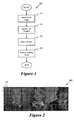
- Figure 1 illustrates a process 100 in accordance with some embodiments of the invention.
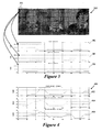
- Figure 2 illustrates a tiled image
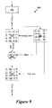
- Figure 3 illustrates the tiled image of Figure 2 divided into three color components for each pixel in a particular tile.
- Figure 4 illustrates three color components for each pixel after the bias is removed.
- Figure 5 illustrates an encoder according to some embodiments.
- Figure 6 illustrates a packet for the data streams of Figure 4 .
- Figure 7 illustrates a multi stage encoder
- Figure 8 illustrates a packet for the encoder of Figure 7 .
- Figure 9 illustrates a decoder according to embodiments of the invention.
- Figure 10 illustrates a decoding process
- Figure 11 illustrates tiles tightly packed in a frame buffer.
- Figure 12 illustrates tiles loosely packed in a frame buffer.
- Figure 13 illustrates stripes in a frame buffer.
- Figure 14 illustrates several test images according to embodiments of the invention.
- Figure 15 illustrates an alternative encoding system of some embodiments.
- Figure 16 illustrates an exemplary packet for the encoding of Figure 15 .
- Figure 17 illustrates an exemplary header for the encoding of Figure 15 and/or the packet of Figure 16 .
- Figure 18 illustrates an encoding system of some embodiments.
- Figure 19 illustrates an exemplary packet for the encoding of Figure 18 .
- Figure 20 illustrates an exemplary header for the encoding of Figure 18 and/or the packet of Figure 19 .
- Figure 21 illustrates a decoding system of some embodiments.
- Figure 22 illustrates an exemplary encoded format.
- Some embodiments of the invention include an efficient lossless image compression scheme that minimizes storage and bus bandwidth requirements. These embodiments are particularly adapted for use with one or more systems on a chip (SOCs) for mobile systems.
- SOCs systems on a chip
- a particular implementation includes a simple lossless compression algorithm to reduce the total storage space for an image.
- the reduced storage space required for the image has additional benefits such as, for example, it reduces the read and/or write bandwidth loads on the bus, which further advantageously improves the overall performance of the system.
- certain frame buffer implementations that take advantage of the algorithm.
- images that are processed and stored in memory are of the fully sampled type and occupy a full eight bits to represent a pixel in color.
- not all the pixels within an image need all of the eight bits to represent the colors faithfully.
- Some embodiments take advantage of the areas of an image that have smaller ranges in color, and thus in coefficient values. These embodiments preferably re-quantize the color coefficients by using a reduced number of bits.
- Embodiments of the invention further desirably achieve a higher compression ratio for images that have been low pass filtered and/or images that have many regions of similar color. Further, these embodiments are applicable to a variety of data formats such as, for example, YCbCr or RGB.
- Figure 1 illustrates a particular embodiment that involves a process 100 for compressing an image.
- the process 100 begins at the step 110, where the image is received and tiled.
- tiling the image comprises dividing the image pixels into discrete sets.
- the process 100 transitions to the step 120, where the colors for each pixel in a tile are separated.
- the tile is separated into three color streams, such as red, green, and blue, for example.
- each pixel's color value is represented by using eight bits, and the color for the tile is treated as three streams of eight-bit values, one stream for each color.
- each tile is of M x M size, then there are three streams of M ⁇ 2 number of eight-bit values.
- each stream e.g., for red, green, and blue
- the process 100 transitions to the step 130, where a minimum value (the bias) for each of the color streams is determined and subtracted from each of the streams.
- the resulting stream of subtracted values typically contains values that are smaller than the original stream.
- the process 100 transitions to the step 140, where the leading zeros are removed from each color stream value.
- the smaller range of values in each of the streams after the subtraction is represented with a reduced number of bits by removing the leading zeros such that the maximum value can still be represented in the remainder of the subtraction.
- a single color stream for the tile contains color values for sixteen pixels. If the maximum value in the red stream is only six, for example, then by removing the leading zeros, only three bits are needed to represent each value in this stream, since the maximum value within the stream is "110" in the corresponding binary code, for this example.
- Figure 2 illustrates the method and/or encoder described above in operation on an exemplary image 200.
- the image is preferably divided into tiles, such as the exemplary first tile 201.
- the tiling step typically reduces the variation in pixel values for a stream.
- areas of the image do not have large variations in pixel value, such that not all values of the full eight bit pixel depth are needed to represent all the colors within the tile.
- Figures 3 and 4 graphically illustrate how redundant information in an image 300 is reduced through the removal of bias and/or leading zeros.
- the color components for a tile 301 are divided into three streams, namely, streams for red 302, green 304, and blue 306 color.
- the coefficients for each color stream are diagrammatically illustrated in a chart format.
- a four-by-four tile has sixteen pixels, while the y-axis includes the coefficient value corresponding to a magnitude for each pixel.
- the raw image data is typically in an eight bit format, hence the coefficient values range from about 0 to 255.
- Figure 4 illustrates the color components of each stream 402, 404, and 406, after a bias value for each stream is determined and subtracted from the stream.
- the difference information is retained for each pixel in the tile. Accordingly, the differences between pixel coefficient values are illustrated more clearly in Figure 4 .
- the largest value within the three streams red, green, and blue
- the minimum necessary bit width is advantageously calculated to faithfully represent the remainder of the subtraction.
- any excess leading zeros are preferably removed or concatenated, as further described below in relation to Figures 5 through 8 .
- Figure 5 illustrates a block diagram for an encoder 500 of some embodiments.
- the encoder 500 packs the encoded color information and the header into a tile.
- the header describes how to decode the tile.
- the encoder 500 includes a memory 502 and a stats block 504, which each receive an input data stream.
- the memory 502 typically comprises a type of random access memory (RAM) that has sufficient dimensions to store the stream values for a tile, while the stats block 504 is for sorting the values of the tile from low to high, for example.
- RAM random access memory
- the memory 502 outputs to a subtractor 506 that also receives a bias input from the stats block 504.
- the bias comprises the lowest value in the tile as determined by the stats block 504.
- the subtractor 506 subtracts the bias from the stream values from the memory 502, and outputs to a decoder 508.
- the decoder 508 advantageously outputs the minimum number of bits required to represent the result of the subtractor 506, and outputs the bits to a packer 510.
- the illustrated implementation includes a one-to-eight decoder 508, that outputs the minimum number of bits needed based on the storage_size received from the stats block 504.
- the decoder 508 and other components of the system 500 including variations in bus widths and number of bits.
- the packer 510 also receives a tile_start_address, the bias, a storage_size, and a tile_size (from the stats block 504), and outputs a compressed data stream for the particular tile.
- the output of the packer 510 is in the form of one or more packets. The packets of these embodiments are further described in relation to Figure 6 .
- Figure 6 illustrates a packet 600, for the streams of Figure 4 .
- the packet 600 includes fields for tile_size 602, bias 604, storage_size 606, that form the header of the packet 600, and a field for pixel data 608.
- the bias and the bits needed to represent the remainder are packed into the header and concatenated with the remainder values for each stream (red, green and blue).
- a total of 180 bits is needed per tile, for storage, retrieval, and/or display.
- These 180 bits include 36 bits for the header, and 48 bits for the pixel data of each stream.
- 180 bits 36 header bits + 3 streams * 3 bits / pixel * 16 pixels / tile.
- the header of this example uses the following format for three parameters, namely, bias, storage_size, and tile_size:
- a second level of encoding is optionally performed on the remainder values to further increase the compression ratio.
- This second level of compression further reduces the bit width of each value in the color stream by rounding the subtracted values and dividing the values by a factor. For instance, the values are rounded to the nearest even number, and/or divided by two, in a particular embodiment.
- the second compression is lossy because the odd valued remainder values, after the subtraction of the bias from the pixel coefficient values in the original tile, will loose one quantization level or one least significant bit (LSB) during the process of encoding and decoding (dividing by two by the encoder and multiplying by two by the decoder).
- LSB least significant bit
- the second compression stage advantageously results in an improvement of up to 12.5% in the compression ratio.
- the second compression is selectively enabled or disabled such as by software, for example, depending on a desired image quality, and/or a desired compression ratio.
- the divisor factor is preferably any multiple of two, such as four, eight, and sixteen, for example. Larger factors result in higher lossy stage compression, and with a corresponding loss of quality. However, the lower resolution of reduced pixel information is desirable at times, such as in a preview, low power, and/or standby mode.
- a bit shifter conveniently provides the divide function in digital logic, to easily implement a selectable N-bit lossy encoder, where the shifter shifts one least significant bit, for a 1-bit lossy encoder.
- Figure 7 illustrates an embodiment that includes a first level (lossless) and a second level (lossy) encoder 700.
- the encoder 700 includes a memory 702, a stats block 704, a subtractor 706, a decode unit 708, and a packer 710. These components are preferably coupled and operate as described above in relation to Figure 5 .
- the two stage encoder 700 further includes an additional stage that includes a shift module 712, a subtractor 714, and two multiplexers 716 and 718.
- the two multiplexers receive a lossy_enable signal that selects either the first (lossless) stage encoding only, or both the first (lossless) and second (lossy) stages for encoding.
- the shift module 712 is typically configured to provide rounding, and/or divide-by-two or truncating operations. As is recognized by one of ordinary skill, dividing is conveniently provided by selectively shifting bits. For instance, a right shift of one bit advantageously results in a divide by two operation upon bits in a register, while a shift of two bits divides by four.
- the shift module 712 and the multiplexer 716 are coupled between the subtractor 706 and the decoder 708, such that the multiplexer 716 receives the output of the subtractor 706 and the output of the shift module 712, and provides the output of one or the other to the decoder 708, dependent on the lossy_enable signal.
- the subtractor 714 and the multiplexer 718 are coupled between the stats block 704 and the packer 710, such that the multiplexer 718 selects the output of the stats block 704 or the output of the subtractor 714, and provides the selected output to the packer 710 as the storage_size.
- the subtractor 714 selectively decrements the storage_size by 1, when the lossy stage is enabled.
- FIG 8 illustrates an exemplary packet 800 for the encoder of Figure 7 .
- the packet 800 includes a header that has fields for tile_size 802, bias 804, and storage_size 806, and a field for pixel data 808.
- the tile_size is advantageously reduced to only two bits, with a tile_size of four pixels by four pixels.
- the storage_size for each stream is only three bits, after operation of both the lossless and the lossy stages.
- the tile_size field is omitted in embodiments having fixed and/or predetermined tile sizes, for additional overhead savings in encoding, transmission, processing, and/or storage.
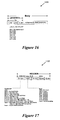
- Figure 9 illustrates a decoder 900 in accordance with some embodiments.
- the decoder 900 includes a data fetch 902 that receives input data, and outputs to an unpacker 904 and a header decode module 906.
- the unpacker 904 extends any missing leading zeros to form an eight bit wide format for each pixel in the received input data, and outputs the eight bit wide data to an adder 908.
- the adder 908 receives the bias from the header decoder 906, which extracts the information contained in the header fields.
- the adder 908 adds the bias (in eight bit format) to the received value for each pixel, and outputs the summed values to a memory 910.
- the received data often comprises a stream for a tile of pixels, hence the memory 910 of these embodiments preferably has the dimensions of the tile of pixels tile_size, as received from the header decode module 906, or alternatively, as predetermined and/or fixed within the system 900.
- the output of the memory 910 are the decoded pixel values for the particular stream of the particular tile.
- the illustrated implementation of the decoder 900 performs the opposite steps of the encoders described above.
- FIG. 10 illustrates a process 1000 that summarizes the steps of the decoder of Figure 9 .
- the process 1000 begins at the step 1010, where a set of incoming bits are received. Then the process 1000 transitions to the step 1020, where the incoming bits are parsed to extract the header. Once the header is extracted, then the process 1000 transitions to the step 1030, where the bits in the header are used to determine information about a set of parameters for the system such as, for example, a tile_size, a bias, and/or a number of bits used per encoded stream. Next, at the step 1040, the pixel bits are unpacked and added to the bias to result in a decoded pixel value for the particular stream, of the particular tile transmitted in the set of incoming bits. Then, the process 1000 concludes.
- the first implementation requires that the compressed tiles be packed tightly together in one long stream of bits.
- the tightly packed tiles are in turn stored tightly in the frame buffer.
- the tightly packed storage of tiles in the frame buffer efficiently uses storage resources and, further, enables the most efficient use of the bus. For instance, with a tightly packed frame buffer, the data fetch unit in the decoder is able to use the maximum burst size for every transaction on the bus.
- This tightly packed implementation also efficiently uses memory, and is particularly useful for applications that do not need to access the tiles in the frame buffer randomly.
- a liquid crystal display (LCD) controller is one such processing block that would use the tightly packed frame buffer.
- Figure 11 illustrates tightly packed tiles in a frame buffer 1100.
- the tightly packed tiles illustratively labeled tile1, tile2, tile3, ... tileN, have a boundary 1104, that is different than the original frame buffer boundary 1102.
- the packed tiles have reduced storage requirements.
- some embodiments store the compressed tiles in a loosely packed format such that the addresses of the individual tiles can be calculated by using certain parameter, for example, by using tile width, tile height, and/or the y-stride.
- the second implementation scheme places the compressed tiles in memory by using a pre-allocated format. For instance, some of these implementations locate or address each tile starting from a point in memory that is of constant offset in bytes from neighboring tiles or stripes of tiles. The tiles at each pre-allocated address are compressed and require less space in memory for storage than the pre-allocated space.
- the advantage of this implementation is that the starting point for each of the tiles or stripe of tiles in the frame buffer is conveniently determined through address calculations by using a particular attribute, such as, for example a y-stride, a tile size, and/or a stripe size. Accordingly, applications have access to the individual tiles in the frame buffer in a random access fashion.
- Figure 12 illustrates loosely packed tiles in a frame buffer 1200 that has a frame boundary 1202.
- the frame buffer 1200 includes compressed tiles 1 through N, that have variable sizes, but that are located in fixed sized addressable locations.
- Each addressable location has a predetermined fixed width of tile_w, and height of tile_h.
- the unused space in each addressable location is left blank such that each location is randomly accessible.
- a y_stride parameter is defined as the width of the frame buffer, and the pre-allocated address locations occupy a fixed multiple of the width of the frame buffer or y_stride.
- Figure 13 illustrates that the compressed and/or encoded pixel data is alternatively packed into a frame buffer 1300 in striped format.
- the addressable locations for each stripe, stripe 1 through stripeN has fixed dimensions (height and width).
- a stripe is defined to be tile_height x frame_width of the frame buffer, while the y_stride is the width of the frame buffer 1300.
- a tile boundary based packing scheme such as illustrated in Figure 12
- the entire stripe must be read and decompressed before operating on the tile.
- the striping configuration of Figure 13 has certain advantages. For instance, when the y_stride or image width is about 1024 pixels, then a single stripe preferably contains 256 tiles, for a tile_size of four by four pixels.
- a page load of, for example, SDRAM advantageously loads all 256 tiles, which is a more efficient use of the bus, memory, and page loads. The efficiency is both in terms of speed of image loading, and in terms of power efficiency, since each load and/or refresh of page memory requires power and/or delay due to a latency.
- RGB888 format was compressed using code written in MATLAB and the compression ratios compared to results produced by another lossless compression scheme, namely, conventional run length encoding.
- tile sizes were used during the simulations, and the 4x4 tile size similar to the examples described above yielded good results.
- Table 1 below shows the comparisons between conventional RLE24 encoding and embodiments of the invention, including the Level1 (lossless), as well as Level2 (lossy) encoding schemes described above.
- test images used to evaluate the tile compression scheme include roost, mobile, qc, vplayer, friends, wanted, starcraft, diablo2, Adobe text, icons, hp, hp1, and hp2. These images are visually presented as an unpacked and decoded group 1400 in Figure 14 , which indicates little or no perceivable loss of visual quality.
- Table 1 below presents exemplary results obtained by using conventional RLE24 encoding versus the tile encoding methods of some embodiments.
- One of ordinary skill recognizes variations in the compression ratios for alternative embodiments. For instance, some implementations of the invention have shown even greater compression ratios.
- Level1 and Level2 (lossy) implementations are further advantageously applied to motion picture images or video.
- Table 2 presents the application of embodiments described above to YCbCr420 movie clips. As noted in Table 2, the test movie clips are listed in the left column, while the compression ratio for each clip is reported in the right column, and is averaged over 100 frames.
- the maximum error in color is one least significant bit (LSB), or one quantization level, for colors having pixel coefficient values that have odd valued remainder values as a result of the subtraction of the bias. There is no error for colors having pixels that have even valued remainder values after the subtraction of the bias. Moreover, there is no noticeable artifact in the images even for the Level2 (lossy) compression. Accordingly, implementations of the invention provide compression without a significant tradeoff in quality.
- the compression ratio advantageously achieved by some embodiments is given below.
- Compression ratio total_bits_in_compressed_frame + header_bits total_bits_in_uncompressed frame * 100
- Figure 15 illustrates an alternative encoding system 1500 of some embodiments.
- the encoding system 1500 includes a memory 1502 and a stats block 1504, which each receive an input data stream.
- the data includes 24 bits, or eight bits for each of three colors, RGB, YCrCb, and the like.
- the memory 1502 typically comprises a type of random access memory (RAM) that has sufficient dimensions to store the stream values for a tile, while the stats block 1504 is for sorting the values of the tile from low to high, for example.
- the memory 1502 is for receiving 4x4 tiles.
- the stats block 1504 advantageously determines a variety of useful values. For instance, the stats block 1504 sorts the incoming tri-chromatic data values, and preferably uses the minimum coefficient of each color as a bias value for the color. The bias values are output by using 24 bits, or eight bits for each color. The stats block 1504 further determines the storage size for the remainder, which it outputs to a packer by using nine bits. The stats block 1504 determines an encode_type and a total bytes in the compressed tile and outputs these to a header module 1520. The header module 1520 also receives the bias values from the stats block 1504 and generates a header, which is shown in Figure 17 .
- the memory 1502 outputs to a subtractor 1506 that also receives a bias input from the stats block 1504.
- the bias comprises the lowest value in the tile as determined by the stats block 1504.
- the subtractor 1506 subtracts the bias from the stream values from the memory 1502, and outputs to a packer 1510.
- the packer 1510 also receives a tile_start _address, the bias, a storage_size, and a tile_size (from the stats block 1504), and outputs a compressed data stream for the particular tile.
- the output preferably comprises the minimum number of bits needed based on the storage_size received from the stats block 1504.
- One of ordinary skill recognizes different implementations for the packer 1510 and other components of the system 1500, including variations in bus widths and number of bits.
- the output of the packer 1510 is in the form of one or more packets.
- the packets of these embodiments are further described in relation to Figure 16 , while the header is illustrated in Figure 17 .
- FIG 16 illustrates an exemplary packet 1600 for the encoding of Figure 15 .
- the packet 1600 includes a body that preferably has a preamble of nine bits, or three bits for each color such as, for example, r_size, g_size, and b_size.
- the size needed for each color is advantageously encoded by using a three-bit code format. More specifically, the number of bits to encode each color varies from one to eight bits, depending on the code (e.g., 000 for one bit, or 111 for eight bits).
- the body further includes the data for a compressed tile, such as in RGB interleaved format, for instance.
- Figure 17 illustrates an exemplary header 1700 for the encoding of Figure 15 and/or the packet of Figure 16 .
- the header 1700 includes encode_type, number-of-bytes, and tri-chromatic bias values.
- the header 1700 uses, for example, four bits for encode_type, plus four bits for the number-of-bytes, plus 24 bits or eight bits for the bias of each of three colors.
- the number-of-bytes field represents sizes in multiples of eight that are from eight-bytes (0001) to 56 bytes (0111).
- the encode_type field allows for multiple encoding schemes, as shown in the figure.
- Figure 18 illustrates an encoding system 1800 of some embodiments. More specifically, Figure 18 illustrates an embodiment that includes a first level (lossless) and a second level (lossy) encoder 1800. As shown in this figure, the encoder 1800 includes a memory 1802, a stats block 1804, a subtractor 1806, and a packer 1810. These components are preferably coupled and operate as described above in relation to Figure 15 .
- the memory 1802 and the stats block 1804 each receive an input data stream.
- the data includes 24 bits, or eight bits for each of three tri-chromatic colors, RGB, YCrCb, and the like.
- the memory 1802 typically comprises a type of random access memory (RAM) that has sufficient dimensions to store the stream values for a tile, while the stats block 1804 is for sorting the values of the tile from low to high, for example.
- the memory 1802 is for receiving 4x4 tiles.
- the stats block 1804 advantageously determines a variety of useful values. For instance, the stats block 1804 sorts the incoming tri-chromatic data values, and preferably uses the minimum coefficient of each color as a bias value for the color. The stats block 1804 preferably outputs the bias values by using 24 bits, or eight bits for each color. The stats block 1804 further determines the storage size for the remainder, which it outputs by using nine bits to a subtractor 1814 and a multiplexer 1818, which are further described below. The stats block 1804 determines an encode_type and a total of bytes in the compressed tile and outputs these to a header module 1820. The header module 1820 also receives the bias values from the stats block 1804 and generates a header, which is shown in Figure 20 .
- the memory 1802 outputs to a subtractor 1806 that also receives a bias input from the stats block 1804.
- the bias comprises the lowest value in the tile as determined by the stats block 1804.
- the subtractor 1806 subtracts the bias (received via the stats block 1804) from the stream values from the memory 1802, and outputs to a multiplexer 1816 and a shifter 1812.
- the multiplexer 1816 selects the output of the subtractor 1806 or the ouptut of the shifter 1812 based on a lossy compression enable signal (lossy_comp_enable) and outputs to a packer 1810.
- the packer 1810 also receives a Tile_start_address, a Tile_size, and the storage_size (via the stats block 1804), and outputs the minimum number of bits needed based on the storage_size received from the stats block 1804.
- a Tile_start_address receives a Tile_start_address
- a Tile_size receives a Tile_size from the stats block 1804.
- the storage_size receives a Tile_start_address, a Tile_size, and the storage_size (via the stats block 1804), and outputs the minimum number of bits needed based on the storage_size received from the stats block 1804.
- the packer 1810 and other components of the system 1800 including variations in bus widths and number of bits.
- the packer 1810 outputs a compressed data stream for the particular tile.
- the output of the packer 1810 is in the form of one or more packets.
- the packets of these embodiments are further described in relation to Figure 19 , while the header is illustrated by Figure 20 .
- the two stage encoder 1800 further includes an additional stage that includes the shift module 1812, the subtractor 1814, and the two multiplexers 1816 and 1818.
- the two multiplexers receive a lossy_comp_enable signal that selects either the first (lossless) stage encoding only, or both the first (lossless) and second (lossy) stages for encoding.
- the shift module 1812 is typically configured to provide rounding, and/or divide-by-two or truncating operations. As is recognized by one of ordinary skill, dividing is conveniently provided by selectively shifting bits. For instance, a right shift of one bit advantageously results in a divide by two operation upon bits in a register, while a shift of two bits divides by four.
- the shift module 1812 and the multiplexer 1816 are coupled between the subtractor 1806 and the packer 1810, such that the multiplexer 1816 receives the output of the subtractor 1806 and the output of the shift module 1812, and provides the output of one or the other to the packer 1810, dependent on the lossy_comp_enable signal.
- the subtractor 1814 and the multiplexer 1818 are coupled between the stats block 1804 and the packer 1810, such that the multiplexer 1818 selects the output of the stats block 1804 or the output of the subtractor 1814, and provides the selected output to the packer 1810 as the storage_size.
- the subtractor 1814 selectively decrements the storage_size by one, when the lossy stage is enabled.
- One of ordinary skill recognizes that alternative embodiments decrement the storage size by different amounts such as, for example, 1, 2, 3, 4, or by another number N.
- Figure 19 illustrates an exemplary packet 1900 for the encoding of Figure 18 .
- the packet 1900 includes a body that preferably has a preamble of nine bits, or three bits for each color such as, for example, r_size, g_size, and b_size.
- the size needed for each color is advantageously encoded by using a three-bit code format. More specifically, the number of bits to encode each color varies from one to eight bits, depending on the code (e.g., 000 for one bit, or 111 for eight bits).
- the body further includes the data for a compressed tile, such as in RGB interleaved format, for instance.
- Figure 20 illustrates an exemplary header for the encoding of Figure 18 and/or the packet of Figure 19 .
- the header 2000 includes encode_type, number-of-bytes, and tri-chromatic bias values.
- the header 2000 uses, for example, four bits for encode_type, plus four bits for number-of-bytes, plus 24 bits or eight bits for the bias of each of three colors.
- the number-of bytes field represents sizes, for example, by using four bit codes, in multiples of eight bytes from eight bytes (0001) to 56 bytes (0111).
- the encode_type field allows for multiple encoding schemes, as shown in the figure.
- headers and/or packets of different implementations contain fields and flexibility to handle the outputs of single stage and/or multi stage encodings such as, for example, lossy and/or lossless encoding stages.
- the decoding systems of particular embodiments are similarly configured to handle a variety of encodings as well.
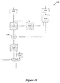
- Figure 21 illustrates a decoding system 2100 of some embodiments.
- the decoder 2100 includes a body fetch 2102 that receives input data typically in the form of packets, and outputs the body of the packets to an unpacker 2104 and a preamble decode module 2017.
- a header fetch 2105 also receives the input data, and outputs to a header decode module 2106 that preferably parses the headers.
- a particular header decode module 2106 outputs four bits of encode_type to the preamble decode module 2107, and 24 bits of bias (eight bits for each of three tri-chromatic colors) to an adder 2108.
- the preamble decode module 2107 outputs nine bits to the unpacker 2104.
- the nine bits preferably indicate the size for each of the three tri-chromatic colors in a three-bit code format such as, for example, rgb_size for systems using red, green, blue.
- the unpacker 2104 extends any missing leading zeros to form an eight bit wide format for each pixel in the received input data, and outputs the eight bit wide data to the adder 2108 mentioned above.
- the adder 2108 receives the bias from the header decoder 2106, which extracts the information contained in the header fields.
- the adder 2108 adds the bias (in eight bit format) to the received value for each pixel, and outputs the summed values to a memory 2110.
- the received data often comprises a stream for a tile of pixels, hence the memory 2110 of these embodiments preferably has the dimensions of the tile of pixels, or of the tile_size, as received from the header decode module 2106, or alternatively, as predetermined and/or fixed within the system 2100, and thereby advantageously reducing the need to transmit these fixed sizes.
- the output of the memory 2110 is the decoded pixel values for the particular stream of the particular tile. For instance, some embodiments output 24 bits that include eight bits for each of three colors.
- the memory 2110 preferably outputs to a multiplexer 2112 and a shifter 2114 such as, for example, a multiply-by-N shifter that outputs to the multiplexer 2112.
- the multiplexer 2112 selects the output of the memory 2110 or the shifted output (via the multiplexer 2114), based on a lossy compression enable signal (lossy_comp_enable).
- the illustrated implementation of the decoder 2100 performs the opposite steps of the encoders 1500 and 1800 described above in relation to Figures 15 and 18 , and further selectively provides for decoding of lossless and/or lossy encodings.
- Figure 22 illustrates an exemplary encoded format 2200.
- uncompressed tiles are advantageously compressed into a smaller format, for instance, by using some of the embodiments described above.
- a particular implementation compresses a 16x16 uncompressed tile into a 4x4 compressed tile.
- Each tile preferably includes a header of four bytes, for example.
- the header uses three bytes for the bias for each of three tri-chromatic colors, or eight bits for each of a blue_bias, a green_bias, and a red_bias.
- One byte is for the encode_type and the number-of-bytes fields. In this case, each of these fields uses four bits of the byte for the two fields.
- 48 tiles are advantageously compressed and then packed into a frame buffer.
- the illustrated implementation 2200 uses the loosely packed format, which includes the advantages of speed and random access described above. Further, in the loosely packed implementation, the unused space that is allocated for each tile is intentionally left blank.
- the particular frame buffer illustrated is twelve tiles wide and four tiles high. Hence for tiles having 4x4 pixels, the frame buffer is 16 pixels wide times three, or 48 pixels wide, and 16 pixels high.
- DSP digital signal processor
- ASIC application specific integrated circuit
- FPGA field programmable gate array
- a general purpose processor may be a microprocessor, but in the alternative, the processor may be any conventional processor, controller, microcontroller, or state machine.
- a processor may also be implemented as a combination of computing devices, e.g., a combination of a DSP and a microprocessor, a plurality of microprocessors, one or more microprocessors in conjunction with a DSP core, or any other such configuration.
- a software module may reside in RAM memory, flash memory, ROM memory, EPROM memory, EEPROM memory, registers, hard disk, a removable disk, a CD-ROM, or any other form of storage medium known in the art.
- An exemplary storage medium is coupled to the processor such that the processor can read information from, and write information to, the storage medium.
- the storage medium may be integral to the processor.
- the processor and the storage medium may reside in an ASIC.
- the ASIC may reside in a user terminal, a personal computer, or a mobile computing and/or telecommunications device.
- the processor and the storage medium may reside as discrete components in a user terminal.
Landscapes
- Engineering & Computer Science (AREA)
- Multimedia (AREA)
- Signal Processing (AREA)
- Compression Or Coding Systems Of Tv Signals (AREA)
- Compression, Expansion, Code Conversion, And Decoders (AREA)
- Compression Of Band Width Or Redundancy In Fax (AREA)
Applications Claiming Priority (2)
| Application Number | Priority Date | Filing Date | Title |
|---|---|---|---|
| US94697207P | 2007-06-28 | 2007-06-28 | |
| US11/855,578 US8331663B2 (en) | 2007-06-28 | 2007-09-14 | Efficient image compression scheme to minimize storage and bus bandwidth requirements |
Publications (2)
| Publication Number | Publication Date |
|---|---|
| EP2012544A2 true EP2012544A2 (de) | 2009-01-07 |
| EP2012544A3 EP2012544A3 (de) | 2009-03-11 |
Family
ID=40011156
Family Applications (1)
| Application Number | Title | Priority Date | Filing Date |
|---|---|---|---|
| EP08006408A Withdrawn EP2012544A3 (de) | 2007-06-28 | 2008-03-31 | Effizientes Bildkomprimierungsschema zur Minimierung der Speicher- und Busbandbreitenanforderungen |
Country Status (7)
| Country | Link |
|---|---|
| US (1) | US8331663B2 (de) |
| EP (1) | EP2012544A3 (de) |
| JP (1) | JP5069349B2 (de) |
| KR (1) | KR101139563B1 (de) |
| CN (1) | CN101796842B (de) |
| TW (1) | TW200910974A (de) |
| WO (1) | WO2009006099A2 (de) |
Cited By (2)
| Publication number | Priority date | Publication date | Assignee | Title |
|---|---|---|---|---|
| EP2773122A1 (de) * | 2013-03-01 | 2014-09-03 | intoPIX s.a. | Verfahren und Vorrichtung zur Kompression eines Wiedergabestroms |
| US9332258B2 (en) | 2013-03-01 | 2016-05-03 | intoPIX SA | Method and device for display stream compression |
Families Citing this family (33)
| Publication number | Priority date | Publication date | Assignee | Title |
|---|---|---|---|---|
| US8699808B2 (en) * | 2007-10-15 | 2014-04-15 | Chih-Ta Star Sung | Method and apparatus of temporary image frame compression |
| US20110249959A1 (en) * | 2010-04-09 | 2011-10-13 | Korea Electronics Technology Institute | Video storing method and device based on variable bit allocation and related video encoding and decoding apparatuses |
| US8989275B2 (en) * | 2010-11-10 | 2015-03-24 | Qualcomm Incorporated | Video processing architecture |
| WO2012176910A1 (ja) | 2011-06-23 | 2012-12-27 | シャープ株式会社 | オフセット復号装置、オフセット符号化装置、画像フィルタ装置、および、データ構造 |
| US9002122B2 (en) * | 2012-07-19 | 2015-04-07 | Omnivision Technologies, Inc. | System and method for improving decoder performance using quantization control |
| US20140029864A1 (en) * | 2012-07-30 | 2014-01-30 | Dror Reif | Compression encoding and decoding method and apparatus |
| US9754560B2 (en) * | 2012-08-20 | 2017-09-05 | Open Invention Network, Llc | Pooling and tiling data images from memory to draw windows on a display device |
| US10791315B2 (en) | 2013-01-04 | 2020-09-29 | Qualcomm Incorporated | Signaling of spatial resolution of depth views in multiview coding file format |
| US9087410B2 (en) * | 2013-01-17 | 2015-07-21 | Qualcomm Incorporated | Rendering graphics data using visibility information |
| EP2951674B1 (de) * | 2013-02-01 | 2019-08-14 | Hitachi Vantara Corporation | Verfahren und vorrichtung zur ermöglichung von feinkörniger, skalierbare speicherzuordnung in einem datenspeichersystem |
| KR20140109128A (ko) * | 2013-03-05 | 2014-09-15 | 삼성전자주식회사 | 데이터 리드 방법과 상기 방법을 수행할 수 있는 장치들 |
| US9135727B2 (en) | 2013-05-07 | 2015-09-15 | Adobe Systems Incorporated | Method and apparatus for reconstructing indexed color spaces |
| US11425395B2 (en) | 2013-08-20 | 2022-08-23 | Google Llc | Encoding and decoding using tiling |
| CN103796018B (zh) * | 2014-01-14 | 2017-09-15 | 齐齐哈尔大学 | 一种遥感影像实时压缩及渐进传输系统 |
| WO2015109598A1 (en) * | 2014-01-27 | 2015-07-30 | Mediatek Singapore Pte. Ltd. | Methods for motion parameter hole filling |
| GB2530312B (en) * | 2014-09-19 | 2016-09-14 | Imagination Tech Ltd | Data compression |
| EP3320683B1 (de) | 2015-07-30 | 2024-09-18 | Zhejiang Dahua Technology Co., Ltd. | Verfahren und systeme zur bildkompression |
| US9794574B2 (en) * | 2016-01-11 | 2017-10-17 | Google Inc. | Adaptive tile data size coding for video and image compression |
| CN105959503A (zh) * | 2016-05-25 | 2016-09-21 | 西北工业大学 | 远程图像预览传输方法及装置 |
| US10511858B2 (en) * | 2016-07-13 | 2019-12-17 | Ati Technologies Ulc | Bit packing for delta color compression |
| KR102646906B1 (ko) | 2016-11-17 | 2024-03-12 | 삼성전자주식회사 | 타일 기반 렌더링 방법 및 장치 |
| US10438597B2 (en) * | 2017-08-31 | 2019-10-08 | Dolby International Ab | Decoder-provided time domain aliasing cancellation during lossy/lossless transitions |
| GB2569645B (en) * | 2017-12-22 | 2022-02-23 | Displaylink Uk Ltd | Managing data for transportation |
| CN111869205B (zh) | 2018-01-19 | 2022-06-10 | Pcms控股公司 | 具有变化位置的多焦平面 |
| JP7722818B2 (ja) | 2018-03-23 | 2025-08-13 | インターデイジタル ヴィーシー ホールディングス インコーポレイテッド | Dibrシステムにおいて立体的視点を生じさせるための、多焦点面ベースの方法(mfp-dibr) |
| US10812828B2 (en) * | 2018-04-10 | 2020-10-20 | At&T Intellectual Property I, L.P. | System and method for segmenting immersive video |
| CN112585963B (zh) * | 2018-07-05 | 2024-04-09 | Pcms控股公司 | 用于2d显示器上的内容的3d感知的近眼焦平面覆盖层的方法和系统 |
| CN110769253A (zh) * | 2018-07-26 | 2020-02-07 | 晨星半导体股份有限公司 | 影像压缩电路及方法 |
| KR102167360B1 (ko) * | 2019-05-24 | 2020-10-19 | 서울과학기술대학교 산학협력단 | 화면 전송 방법 및 장치 |
| CN116648913A (zh) | 2020-12-23 | 2023-08-25 | 抖音视界有限公司 | 视频解码器初始化信息约束 |
| US11663730B2 (en) * | 2021-02-19 | 2023-05-30 | Toyota Motor Engineering & Manufacturing North America, Inc. | Systems and methods for an improved camera system using a graded lens and filters to estimate depth |
| CN114465826B (zh) * | 2022-04-11 | 2022-07-15 | 深圳市天兴诚科技有限公司 | 编码技术的数据加密方法、系统及储存介质 |
| KR20250059427A (ko) * | 2022-08-29 | 2025-05-02 | 인터디지털 씨이 페이튼트 홀딩스, 에스에이에스 | 볼륨 장면의 렌더링된 뷰포트에 대한 누락된 속성 값 전송 |
Family Cites Families (23)
| Publication number | Priority date | Publication date | Assignee | Title |
|---|---|---|---|---|
| JPH0793724B2 (ja) | 1984-12-21 | 1995-10-09 | ソニー株式会社 | テレビジョン信号の高能率符号化装置及び符号化方法 |
| JPS6370682A (ja) | 1986-09-12 | 1988-03-30 | Sony Corp | コンポ−ネント信号の高能率符号化装置 |
| US5166987A (en) * | 1990-04-04 | 1992-11-24 | Sony Corporation | Encoding apparatus with two stages of data compression |
| JP2844861B2 (ja) | 1990-06-29 | 1999-01-13 | ソニー株式会社 | 画像信号の高能率符号化装置及び符号化方法 |
| GB9113469D0 (en) | 1991-06-21 | 1991-08-07 | Anamartic Ltd | Data storage management systems |
| JP3162792B2 (ja) * | 1992-04-17 | 2001-05-08 | キヤノン株式会社 | 画像処理装置 |
| JP3874544B2 (ja) * | 1998-07-10 | 2007-01-31 | 三菱電機株式会社 | 色変換装置および色変換方法 |
| JPH07274021A (ja) * | 1994-03-31 | 1995-10-20 | Canon Inc | 画像処理装置 |
| US5878168A (en) * | 1995-06-05 | 1999-03-02 | Sony Corporation | Method and apparatus for picture encoding and decoding |
| US5793314A (en) | 1996-07-03 | 1998-08-11 | Motorola, Inc. | Method and apparatus for bound-based adaptive entropy encoding/decoding |
| JP3687080B2 (ja) * | 1996-07-17 | 2005-08-24 | ソニー株式会社 | 画像符号化装置および画像符号化方法、画像復号化装置および画像復号化方法、並びに記録媒体 |
| JP3748088B2 (ja) * | 1996-07-17 | 2006-02-22 | ソニー株式会社 | 画像処理装置および方法、並びに学習装置および方法 |
| JPH1032495A (ja) | 1996-07-18 | 1998-02-03 | Sony Corp | データ処理装置および方法 |
| JP3342380B2 (ja) | 1997-12-24 | 2002-11-05 | キヤノン株式会社 | 符号化及び復号装置とそれを適用した画像処理装置 |
| AUPP686598A0 (en) | 1998-10-30 | 1998-11-26 | Canon Kabushiki Kaisha | A method and apparatus for representing a digital image to provide a coded representation |
| US20040136600A1 (en) * | 1999-08-24 | 2004-07-15 | Yfantis Evangelos A. | Visually lossless still image compression for RGB, YUV, YIQ, YCrCb, K1K2K3 formats |
| KR100344900B1 (ko) * | 2000-05-15 | 2002-07-20 | 주식회사 이시티 | 영상 압축/복원 장치 및 그 방법 |
| JP2003189109A (ja) | 2001-10-09 | 2003-07-04 | Canon Inc | 画像処理装置及び方法、並びにコンピュータ・プログラム |
| JP4061917B2 (ja) | 2002-02-12 | 2008-03-19 | ソニー株式会社 | 符号化処理装置、復号処理装置、および方法、並びにコンピュータ・プログラム |
| JP2003259393A (ja) | 2002-03-01 | 2003-09-12 | Sony Corp | 符号化処理装置、復号処理装置、および方法、並びにコンピュータ・プログラム |
| US7764832B2 (en) * | 2003-12-16 | 2010-07-27 | Seiko Epson Corporation | System and method for processing image data for color space conversion |
| KR100679027B1 (ko) * | 2005-01-19 | 2007-02-05 | 삼성전자주식회사 | Dc 성분의 손실 없이 영상을 코딩하는 방법 및 장치 |
| JP4321496B2 (ja) * | 2005-06-16 | 2009-08-26 | ソニー株式会社 | 画像データ処理装置、画像データ処理方法およびプログラム |
-
2007
- 2007-09-14 US US11/855,578 patent/US8331663B2/en not_active Expired - Fee Related
-
2008
- 2008-03-31 EP EP08006408A patent/EP2012544A3/de not_active Withdrawn
- 2008-06-24 JP JP2010515030A patent/JP5069349B2/ja not_active Expired - Fee Related
- 2008-06-24 WO PCT/US2008/068010 patent/WO2009006099A2/en not_active Ceased
- 2008-06-24 CN CN200880021891.1A patent/CN101796842B/zh not_active Expired - Fee Related
- 2008-06-24 KR KR1020107002058A patent/KR101139563B1/ko not_active Expired - Fee Related
- 2008-06-27 TW TW097124394A patent/TW200910974A/zh unknown
Non-Patent Citations (1)
| Title |
|---|
| KONDO T ET AL: "ADAPTIVE DYNAMIC RANGE CODING SCHEME FOR FUTURE CONSUMER DIGITAL VTR", VIDEO, AUDIO AND DATA RECORDING. INTERNATIONAL CONFERENCE, LONDON, GB, vol. 79, 1 January 1988 (1988-01-01), pages 219 - 226, XP000472806 * |
Cited By (3)
| Publication number | Priority date | Publication date | Assignee | Title |
|---|---|---|---|---|
| EP2773122A1 (de) * | 2013-03-01 | 2014-09-03 | intoPIX s.a. | Verfahren und Vorrichtung zur Kompression eines Wiedergabestroms |
| US9332258B2 (en) | 2013-03-01 | 2016-05-03 | intoPIX SA | Method and device for display stream compression |
| EP4072136A1 (de) | 2013-03-01 | 2022-10-12 | intoPIX s.a. | Verfahren und vorrichtung zur anzeige der stream-kompression |
Also Published As
| Publication number | Publication date |
|---|---|
| JP5069349B2 (ja) | 2012-11-07 |
| KR101139563B1 (ko) | 2012-04-27 |
| KR20100030660A (ko) | 2010-03-18 |
| TW200910974A (en) | 2009-03-01 |
| CN101796842B (zh) | 2012-11-14 |
| JP2010533396A (ja) | 2010-10-21 |
| WO2009006099A3 (en) | 2009-02-19 |
| WO2009006099A2 (en) | 2009-01-08 |
| EP2012544A3 (de) | 2009-03-11 |
| CN101796842A (zh) | 2010-08-04 |
| US20090003714A1 (en) | 2009-01-01 |
| US8331663B2 (en) | 2012-12-11 |
Similar Documents
| Publication | Publication Date | Title |
|---|---|---|
| US8331663B2 (en) | Efficient image compression scheme to minimize storage and bus bandwidth requirements | |
| US7158679B2 (en) | Image compression with tile alignment | |
| US9232226B2 (en) | Systems and methods for perceptually lossless video compression | |
| US8923613B2 (en) | Image compression device, image compression method, integrated circuit, program, and picture display apparatus | |
| US6008745A (en) | Variable length decoding using lookup tables | |
| US8558909B2 (en) | Method and apparatus for generating compressed file, camera module associated therewith, and terminal including the same | |
| EP2227024B1 (de) | Verfahren und Vorrichtung zur Kompression und Speicherung von Bilddaten | |
| US7570819B2 (en) | Method and apparatus for displaying images with compression mechanism | |
| US8989275B2 (en) | Video processing architecture | |
| CN106464923A (zh) | 用于在比特流中用信号通知ldr画面的画面/视频格式和根据所述ldr画面和照明画面获得的解码的hdr画面的画面/视频格式的方法和设备 | |
| WO2008122913A2 (en) | Decoder for selectively decoding predetermined data units from a coded bit stream | |
| US20210344900A1 (en) | Image processing device | |
| TWI705693B (zh) | 用於顯示串流壓縮之基於向量之熵寫碼的裝置及方法 | |
| US6956511B2 (en) | Multi-symbol/coefficient decode operation for Huffman codes | |
| EP4443879A1 (de) | Bildverarbeitungsvorrichtung und betriebsverfahren dafür | |
| EP2222087A1 (de) | Bittiefen-Hochskalierung im RGB-Farbbereich zur Verringerung der Fehlerausbreitung aufgrund der Umwandlung in den YUV-Farbbereich | |
| CN101406034B (zh) | 使用限定符水印的压缩方案及使用该压缩方案在帧存储器中临时存储图像数据的装置 | |
| US20210352303A1 (en) | Method for processing transform coefficients | |
| US6008853A (en) | Sub-frame decoder with area dependent update rate for digital camcorder transmission standard | |
| EP2315445A1 (de) | Videokomprimierung | |
| US20220353482A1 (en) | Image signal processor, method of operating the image signal processor and image processing system including the image signal processor | |
| US10893297B2 (en) | Processing image data using tiered bit-layers | |
| WO2020231893A1 (en) | Packing of subpixel rendered data for display stream compression | |
| CN113556540A (zh) | 图像显示设备的固定比压缩方法和系统 | |
| AU2017225027A1 (en) | Method, apparatus and system for encoding and decoding video data |
Legal Events
| Date | Code | Title | Description |
|---|---|---|---|
| PUAI | Public reference made under article 153(3) epc to a published international application that has entered the european phase |
Free format text: ORIGINAL CODE: 0009012 |
|
| AK | Designated contracting states |
Kind code of ref document: A2 Designated state(s): AT BE BG CH CY CZ DE DK EE ES FI FR GB GR HR HU IE IS IT LI LT LU LV MC MT NL NO PL PT RO SE SI SK TR |
|
| AX | Request for extension of the european patent |
Extension state: AL BA MK RS |
|
| PUAL | Search report despatched |
Free format text: ORIGINAL CODE: 0009013 |
|
| AK | Designated contracting states |
Kind code of ref document: A3 Designated state(s): AT BE BG CH CY CZ DE DK EE ES FI FR GB GR HR HU IE IS IT LI LT LU LV MC MT NL NO PL PT RO SE SI SK TR |
|
| AX | Request for extension of the european patent |
Extension state: AL BA MK RS |
|
| 17P | Request for examination filed |
Effective date: 20090406 |
|
| 17Q | First examination report despatched |
Effective date: 20090515 |
|
| AKX | Designation fees paid |
Designated state(s): AT BE BG CH CY CZ DE DK EE ES FI FR GB GR HR HU IE IS IT LI LT LU LV MC MT NL NO PL PT RO SE SI SK TR |
|
| APBK | Appeal reference recorded |
Free format text: ORIGINAL CODE: EPIDOSNREFNE |
|
| APBN | Date of receipt of notice of appeal recorded |
Free format text: ORIGINAL CODE: EPIDOSNNOA2E |
|
| APBR | Date of receipt of statement of grounds of appeal recorded |
Free format text: ORIGINAL CODE: EPIDOSNNOA3E |
|
| APAF | Appeal reference modified |
Free format text: ORIGINAL CODE: EPIDOSCREFNE |
|
| APBT | Appeal procedure closed |
Free format text: ORIGINAL CODE: EPIDOSNNOA9E |
|
| STAA | Information on the status of an ep patent application or granted ep patent |
Free format text: STATUS: THE APPLICATION IS DEEMED TO BE WITHDRAWN |
|
| 18D | Application deemed to be withdrawn |
Effective date: 20141001 |