EP2012518A2 - Übertragungsvorrichtung und damit versehene Bildgebungsvorrichtung - Google Patents
Übertragungsvorrichtung und damit versehene Bildgebungsvorrichtung Download PDFInfo
- Publication number
- EP2012518A2 EP2012518A2 EP07254523A EP07254523A EP2012518A2 EP 2012518 A2 EP2012518 A2 EP 2012518A2 EP 07254523 A EP07254523 A EP 07254523A EP 07254523 A EP07254523 A EP 07254523A EP 2012518 A2 EP2012518 A2 EP 2012518A2
- Authority
- EP
- European Patent Office
- Prior art keywords
- transfer
- roller
- sheet
- rollers
- separation
- Prior art date
- Legal status (The legal status is an assumption and is not a legal conclusion. Google has not performed a legal analysis and makes no representation as to the accuracy of the status listed.)
- Withdrawn
Links
- 238000000926 separation method Methods 0.000 claims abstract description 56
- 238000007599 discharging Methods 0.000 claims abstract description 18
- 108091008695 photoreceptors Proteins 0.000 description 12
- 239000003086 colorant Substances 0.000 description 5
- 239000000463 material Substances 0.000 description 4
- 238000004140 cleaning Methods 0.000 description 3
- 238000000034 method Methods 0.000 description 3
- JOYRKODLDBILNP-UHFFFAOYSA-N Ethyl urethane Chemical compound CCOC(N)=O JOYRKODLDBILNP-UHFFFAOYSA-N 0.000 description 2
- 239000002033 PVDF binder Substances 0.000 description 2
- 239000004642 Polyimide Substances 0.000 description 2
- 229910052799 carbon Inorganic materials 0.000 description 2
- 238000006243 chemical reaction Methods 0.000 description 2
- 238000010586 diagram Methods 0.000 description 2
- 229920001971 elastomer Polymers 0.000 description 2
- 229920001721 polyimide Polymers 0.000 description 2
- 229920002981 polyvinylidene fluoride Polymers 0.000 description 2
- 239000010935 stainless steel Substances 0.000 description 2
- 229910001220 stainless steel Inorganic materials 0.000 description 2
- 229910000838 Al alloy Inorganic materials 0.000 description 1
- OKTJSMMVPCPJKN-UHFFFAOYSA-N Carbon Chemical compound [C] OKTJSMMVPCPJKN-UHFFFAOYSA-N 0.000 description 1
- 238000003705 background correction Methods 0.000 description 1
- 239000000969 carrier Substances 0.000 description 1
- 230000006835 compression Effects 0.000 description 1
- 238000007906 compression Methods 0.000 description 1
- 239000011231 conductive filler Substances 0.000 description 1
- 239000004020 conductor Substances 0.000 description 1
- 230000008878 coupling Effects 0.000 description 1
- 238000010168 coupling process Methods 0.000 description 1
- 238000005859 coupling reaction Methods 0.000 description 1
- 230000007547 defect Effects 0.000 description 1
- 238000001514 detection method Methods 0.000 description 1
- 239000006185 dispersion Substances 0.000 description 1
- 238000005530 etching Methods 0.000 description 1
- 229920001038 ethylene copolymer Polymers 0.000 description 1
- 229920000840 ethylene tetrafluoroethylene copolymer Polymers 0.000 description 1
- 239000002245 particle Substances 0.000 description 1
- 229920003225 polyurethane elastomer Polymers 0.000 description 1
- 239000011347 resin Substances 0.000 description 1
- 229920005989 resin Polymers 0.000 description 1
- 230000001360 synchronised effect Effects 0.000 description 1
- WFKWXMTUELFFGS-UHFFFAOYSA-N tungsten Chemical compound [W] WFKWXMTUELFFGS-UHFFFAOYSA-N 0.000 description 1
- 229910052721 tungsten Inorganic materials 0.000 description 1
- 239000010937 tungsten Substances 0.000 description 1
Images

Classifications
-
- G—PHYSICS
- G03—PHOTOGRAPHY; CINEMATOGRAPHY; ANALOGOUS TECHNIQUES USING WAVES OTHER THAN OPTICAL WAVES; ELECTROGRAPHY; HOLOGRAPHY
- G03G—ELECTROGRAPHY; ELECTROPHOTOGRAPHY; MAGNETOGRAPHY
- G03G15/00—Apparatus for electrographic processes using a charge pattern
- G03G15/14—Apparatus for electrographic processes using a charge pattern for transferring a pattern to a second base
- G03G15/16—Apparatus for electrographic processes using a charge pattern for transferring a pattern to a second base of a toner pattern, e.g. a powder pattern, e.g. magnetic transfer
-
- G—PHYSICS
- G03—PHOTOGRAPHY; CINEMATOGRAPHY; ANALOGOUS TECHNIQUES USING WAVES OTHER THAN OPTICAL WAVES; ELECTROGRAPHY; HOLOGRAPHY
- G03G—ELECTROGRAPHY; ELECTROPHOTOGRAPHY; MAGNETOGRAPHY
- G03G2215/00—Apparatus for electrophotographic processes
- G03G2215/00135—Handling of parts of the apparatus
- G03G2215/00139—Belt
- G03G2215/00143—Meandering prevention
-
- G—PHYSICS
- G03—PHOTOGRAPHY; CINEMATOGRAPHY; ANALOGOUS TECHNIQUES USING WAVES OTHER THAN OPTICAL WAVES; ELECTROGRAPHY; HOLOGRAPHY
- G03G—ELECTROGRAPHY; ELECTROPHOTOGRAPHY; MAGNETOGRAPHY
- G03G2215/00—Apparatus for electrophotographic processes
- G03G2215/16—Transferring device, details
- G03G2215/1604—Main transfer electrode
- G03G2215/1614—Transfer roll
Definitions
- the present invention relates to a transfer apparatus for transferring a toner image onto a sheet using a belt and an image forming apparatus equipped with the same.
- a transfer apparatus using a transfer belt is utilized as the transfer apparatus for transferring a toner image onto a sheet.
- the sheet is conveyed as it is electrostatically adsorbed onto the transfer belt, and therefore, it allows relatively easy separation immediately after transfer, as compared to the transfer apparatus based on a corona discharge method or on a transfer roller. Further, a wider transfer region formed by a photoreceptor and transfer belt can be provided. This ensures an advantage of stable transfer. For these reasons, this arrangement has been preferably employed, despite its complicated structure.
- the transfer nip (transfer region) formed between the transfer roller and photoreceptor or other image carrier becomes uneven in the longitudinal direction. Thus, uniform transfer performance cannot be obtained.
- the object of the present invention is to solve the aforementioned problems and to provide a transfer apparatus using a transfer belt capable of ensuring the transfer and separation performance as well as the traveling stability of the transfer belt.
- One aspect of the present invention is to provide a transfer apparatus for transferring a toner image onto a sheet having: an endless belt; a plurality of rollers for supporting the endless belt around the plurality of rollers; and a discharge section for corona discharging the sheet, wherein the plurality of rollers includes a transfer roller for forming a transfer nip used to transfer the toner image onto the sheet and a separation roller for separating the sheet from the endless belt, and the transfer roller and the separation roller are straight shaped rollers each having a substantially uniform diameter along the longitudinal direction; and wherein at least one of the plurality of rollers other than the transfer roller and the separation roller is formed into a crown shape in which an axially central portion thereof is larger in outer diameter than both end portions thereof.
- Another aspect of the present invention is to provide the transfer apparatus as described above, wherein the discharge section is provided at a position facing to the separation roller.
- Fig. 1 is an overall cross sectional view representing the image forming apparatus equipped with an image forming apparatus main body A, automatic document feeder DF.
- the image forming apparatus main body A includes an image reading apparatus 1, operation/display section 2, image forming section 4, transfer apparatus 5, fixing apparatus 6, and sheet conveyance system.
- the image forming section 4 contains a photoreceptor 41, charging section 42, exposure section 43, developing device 44 and photoreceptor cleaning section 46.
- the sheet conveyance system is made up of a sheet feeding cassette 10, first sheet feeding device 11, second sheet feeding device 12, sheet ejection device 14, manual sheet feeding device 15, circulating sheet re-feed device 16, and reversing/ejection device 17.
- the document d placed on the document platen of the automatic document feeder DF is conveyed by the sheet feeding device.
- An image on one or both sides of the document d is read by the optional system of the image reading apparatus 1, and is read into the image sensor CCD.
- the analog signal subjected to photoelectric conversion by the image sensor CCD undergoes analog processing, analog-to-digital conversion, shading correction, image compression and the like in the image processing section (not illustrated). After that, image signal is sent to the exposure section 43.
- the photoreceptor 41 is charged by the charging section 42 (negatively charged in the present embodiment).
- An electrostatic latent image is formed by the laser beam from the exposure section 43, and the electrostatic latent image is developed by the developing device 44, whereby a toner image (negatively charged in the present embodiment) is obtained.
- the sheet P stored in the sheet feeding cassette 10 is conveyed from the first sheet feeding device 11.
- the sheet P is synchronized with the toner image by the second sheet feeding device 12 made up of a registration roller, and the traveling position of the leading edge of the sheet P is detected by the detection sensor (not illustrated).
- the information is sent to the control device 100, whereby the time interval of entering the transfer nip section N1 formed between the transfer apparatus 5 and photoreceptor 41 is calculated.
- the toner image is transferred onto the sheet P by the transfer nip section N1 that is formed by the transfer belt 51 of the transfer apparatus 5 and the photoreceptor 1, and the sheet P is conveyed by being statically adsorbed by the transfer belt 51.
- the sheet P conveyed onto the transfer belt 51 is electrically discharged through corona discharging by the separation/discharging electrode 500.
- the sheet P is subjected to curvature-separation by the separation roller 52 and is conveyed to the fixing apparatus 6.
- the image is fixed onto the sheet P by the fixing nip section N2 formed of the fixing roller 61 of the fixing apparatus 6 and the pressure roller 62. After fixing, the sheet P is discharged out of the apparatus by the sheet ejection device 14.
- the transfer apparatus 5 of the invention of the present application will be described in details later.
- the toner remaining on the photoreceptor 41 after transfer and the toner on the transfer belt 51 not yet transferred are removed by the photoreceptor cleaning section 46 and belt cleaning section 506.
- the sheet P with an image formed on the first surface is fed into the circulating sheet re-feed device 16, and is switched back and reversed.
- the sheet P is ejected out of the apparatus by the sheet ejection device 1.
- the sheet P having branched out of the normal ejection passage is switched back and reversed by the reversing/ejection device 17, and is then ejected out of the apparatus by the sheet ejection device 14.
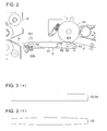
- Fig. 2 is a cross sectional view showing around the transfer apparatus 5.
- a transfer belt 51 is supported by rollers such as a separation roller 52 of stainless steel (SUS), a driven roller 53 of aluminum alloy, a transfer roller 54 of foamed urethane, and a transfer bias roller 55 of stainless steel (SUS).
- the separation roller 52 serves as a drive roller, and is connected with a drive motor through a coupling gear (not illustrated), whereby the drive of the drive motor is transmitted to the transfer belt.
- the transfer belt is driven (moved) at a speed of 200 through 500 mm/sec, for example.
- the surface of the separation roller 52 is coated with rubber to increase friction coefficient.
- transfer roller is also referred to as a "back-up roller”. It is a roller which supports a transfer belt, and is used to form a transfer nip between the transfer roller and an image carrier such as the photoreceptor.
- separation roller refers to the roller to which supports the transfer belt, and is a roller located around the separation position wherein the sheet having been adsorbed by the transfer belt is subjected to curvature separation or other separation.
- the transfer belt is made of such a resin material as polyimide (PI), polyvinylidene fluoride (PVDF) and ethylene copolymer (ETFE) or such a rubber material as polyurethane rubber wherein a conductive filler of carbon or the like is dispersed to adjust resistance, or wherein an ionic conductive material is included.
- PI polyimide
- PVDF polyvinylidene fluoride
- ETFE ethylene copolymer
- rubber material as polyurethane rubber wherein a conductive filler of carbon or the like is dispersed to adjust resistance, or wherein an ionic conductive material is included.
- the transfer voltage to form a transfer field having a polarity reverse to that of the toner is applied to the bias roller 55.
- the back-up roller 54 is formed of foamed urethane.
- a straight shaped roller is used as the bias roller 55. It is also possible to apply transfer voltage using a conductive brush instead of the bias roller 55.
- the separation/discharging electrode 501 is a discharging electrode for corona discharging, and is provided at a position facing to the separation roller 52.
- the separation/discharging electrode 501 is a needle-shaped electrode (also known as the saw-toothed electrode), and the vertexes as the peak portions are arranged at a predetermined pitch over the entire region across the width of the traveling sheet at an interval of about 1 through 5 mm, for example, by etching a 0.1 mm thick SUS plate.
- the DC voltage having the polarity reverse to that of the bias roller or the voltage formed by superimposing the AC voltage to this DC voltage is applied to the needle-shaped electrode. It is also possible to utilize the separation/discharging electrode using a discharge wire of tungsten or the like, instead of the needle-shaped electrode.
- Fig. 3 is a diagram representing the shape of the roller of the transfer apparatus.
- Fig. 3 (a) is a front view representing the transfer roller 54 and separation roller 52
- Fig. 3 (b) is a front view showing the driven rollers 53 (rollers other than transfer roller and separation roller);
- the transfer roller 54 and separation roller 52 has a straight shape wherein the diameter is substantially uniform in the longitudinal direction (axial direction).
- Such a straight shaped roller ensures that the width of the transfer nip N1 formed by the transfer roller 54 and photoreceptor 41 can be made uniform in the axial direction.
- This arrangement provides uniform transfer in the axial direction. Further, the discharging performance for the separation roller 52 using the separation/discharging electrode 501 and the sheet P being conveyed can be made uniform in the axial direction, with the result that the problem resulting from excessive or insufficiency of discharging can be solved.
- the "problem resulting from excessive or insufficiency of discharging" in the sense in which it is used here refers to (1) the case wherein, since toner is reversely charged by partial excessive discharge, the toner once transferred onto the transfer material is redeposited on the surface of the latent image carrier; and (2) the case wherein an image defect is caused by separation failure by partial insufficient discharge, or toner dispersion resulting from separation charge that occurs when the sheet P is separated from the transfer belt.
- the driven roller 53 has a crown shape in which a axially central portion thereof is larger in outer diameter than both end portions thereofs.
- the amount of crown is such that the diameter at the center is larger than the radius on ends by 100 ⁇ m through 2000 ⁇ m.
- the length of the driven roller 53 in the axial direction is about 310 mm through 370 mm.
- crown shaped roller avoids meandering which occurs when the transfer belt 51 is fed. It should be noted in passing that, in the description of the embodiment, reference has been made of an example of using a crown shaped roller as the rollers other than the transfer roller and separation roller. In this connection, it is also possible to use an inverted crown shaped roller as well as a crown shaped roller.
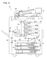
- Fig. 4 is an overall cross sectional view showing the image forming apparatus of another embodiment.
- the members having the same function as those of Fig. 1 are assigned with the same reference numbers, and will not be described to avoid duplication.
- the image forming apparatus of Fig. 4 is a full color type image forming apparatus.
- the developing devices for different colors each include a two-component developer made up of the toner particles of yellow (Y), magenta (M), cyan (C) and black (K) and carriers.
- the toner images of different colors formed by developing the photoreceptors 41 for different colors (reference symbols omitted for M, C and K) by the toners of different colors are transferred primarily onto the intermediate transfer apparatus 45 in the later step.
- the color toner image obtained by superimposing the toner images of different colors by primarily transferring onto the intermediate transfer belt 451 of the intermediate transfer apparatus 45 is secondarily transferred onto the sheet P by the transfer apparatus (secondary transfer apparatus) 5b.
- the sheet P with the color toner image transferred thereon is conveyed to the fixing apparatus 6 wherein the image is fixed thereon. After fixing, the sheet P is ejected out of the apparatus by the sheet ejection device 14.
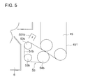
- Fig. 5 is a cross sectional view showing around the transfer apparatus 5b.
- the transfer apparatus 5b includes a straight shaped transfer roller 54b, a separation roller 52b, a drive roller 53b as a crown shaped roller, a transfer belt 51b supported by these rollers, and a separation/discharging electrode 501b.
- the transfer voltage for forming the transfer field having the polarity reverse to that of the toner is applied to the transfer roller 54.
- the amount of crown and the material of each member are equivalent to those of the transfer apparatus 5 shown in Figs. 2 and 3 .
- straight shaped rollers are used as the transfer roller and separation roller, and a crown shaped roller is used as the drive roller as another roller.
- This arrangement provides a transfer apparatus using a transfer belt capable of ensuring the transfer and separation performance as well as the traveling stability of the transfer belt.
- the present invention provides a transfer apparatus and image forming apparatus that ensures the transfer and separation performance as well as the traveling stability of the transfer belt.
Landscapes
- Physics & Mathematics (AREA)
- General Physics & Mathematics (AREA)
- Electrostatic Charge, Transfer And Separation In Electrography (AREA)
Applications Claiming Priority (1)
| Application Number | Priority Date | Filing Date | Title |
|---|---|---|---|
| JP2007177145A JP2009015043A (ja) | 2007-07-05 | 2007-07-05 | 転写装置及び該転写装置を備えた画像形成装置 |
Publications (2)
| Publication Number | Publication Date |
|---|---|
| EP2012518A2 true EP2012518A2 (de) | 2009-01-07 |
| EP2012518A3 EP2012518A3 (de) | 2010-05-05 |
Family
ID=39365617
Family Applications (1)
| Application Number | Title | Priority Date | Filing Date |
|---|---|---|---|
| EP07254523A Withdrawn EP2012518A3 (de) | 2007-07-05 | 2007-11-21 | Übertragungsvorrichtung und damit versehene Bildgebungsvorrichtung |
Country Status (4)
| Country | Link |
|---|---|
| US (1) | US20090010698A1 (de) |
| EP (1) | EP2012518A3 (de) |
| JP (1) | JP2009015043A (de) |
| CN (1) | CN101339393A (de) |
Cited By (1)
| Publication number | Priority date | Publication date | Assignee | Title |
|---|---|---|---|---|
| EP2940530A1 (de) * | 2014-04-02 | 2015-11-04 | Canon Kabushiki Kaisha | Bilderzeugungsvorrichtung |
Families Citing this family (3)
| Publication number | Priority date | Publication date | Assignee | Title |
|---|---|---|---|---|
| JP5472593B2 (ja) * | 2009-08-07 | 2014-04-16 | セイコーエプソン株式会社 | 転写装置および画像形成装置 |
| JP2011221230A (ja) * | 2010-04-08 | 2011-11-04 | Konica Minolta Business Technologies Inc | 画像形成装置 |
| US12339602B2 (en) | 2022-09-15 | 2025-06-24 | Canon Kabushiki Kaisha | Image forming apparatus |
Citations (3)
| Publication number | Priority date | Publication date | Assignee | Title |
|---|---|---|---|---|
| JPS63221345A (ja) | 1987-03-11 | 1988-09-14 | Fuji Photo Film Co Ltd | 加熱現像装置 |
| JPH1020716A (ja) | 1996-06-28 | 1998-01-23 | Konica Corp | 画像形成装置 |
| JP2007177145A (ja) | 2005-12-28 | 2007-07-12 | Kao Corp | 液体洗浄剤 |
Family Cites Families (5)
| Publication number | Priority date | Publication date | Assignee | Title |
|---|---|---|---|---|
| JP4218914B2 (ja) * | 1999-07-06 | 2009-02-04 | キヤノン株式会社 | 転写搬送ベルトおよびそれを有する画像形成装置 |
| JP3647709B2 (ja) * | 2000-02-17 | 2005-05-18 | シャープ株式会社 | 画像形成装置 |
| JP2003345142A (ja) * | 2002-05-27 | 2003-12-03 | Canon Inc | 画像形成装置 |
| US6785486B2 (en) * | 2002-11-07 | 2004-08-31 | Kabushiki Kaisha Toshiba | Image forming apparatus |
| JP4207893B2 (ja) * | 2004-12-28 | 2009-01-14 | ブラザー工業株式会社 | ベルトユニットおよび画像形成装置 |
-
2007
- 2007-07-05 JP JP2007177145A patent/JP2009015043A/ja active Pending
- 2007-11-21 EP EP07254523A patent/EP2012518A3/de not_active Withdrawn
- 2007-11-27 US US11/945,972 patent/US20090010698A1/en not_active Abandoned
-
2008
- 2008-07-04 CN CNA2008101330179A patent/CN101339393A/zh active Pending
Patent Citations (3)
| Publication number | Priority date | Publication date | Assignee | Title |
|---|---|---|---|---|
| JPS63221345A (ja) | 1987-03-11 | 1988-09-14 | Fuji Photo Film Co Ltd | 加熱現像装置 |
| JPH1020716A (ja) | 1996-06-28 | 1998-01-23 | Konica Corp | 画像形成装置 |
| JP2007177145A (ja) | 2005-12-28 | 2007-07-12 | Kao Corp | 液体洗浄剤 |
Cited By (2)
| Publication number | Priority date | Publication date | Assignee | Title |
|---|---|---|---|---|
| EP2940530A1 (de) * | 2014-04-02 | 2015-11-04 | Canon Kabushiki Kaisha | Bilderzeugungsvorrichtung |
| US9658577B2 (en) | 2014-04-02 | 2017-05-23 | Canon Kabushiki Kaisha | Image forming apparatus having transfer belt rollers of specific shapes |
Also Published As
| Publication number | Publication date |
|---|---|
| EP2012518A3 (de) | 2010-05-05 |
| CN101339393A (zh) | 2009-01-07 |
| JP2009015043A (ja) | 2009-01-22 |
| US20090010698A1 (en) | 2009-01-08 |
Similar Documents
| Publication | Publication Date | Title |
|---|---|---|
| US6697595B2 (en) | Method and apparatus for forming an image with no degradation | |
| US10353323B2 (en) | Image forming apparatus | |
| US8620171B2 (en) | Transfer device and image forming apparatus | |
| EP2012518A2 (de) | Übertragungsvorrichtung und damit versehene Bildgebungsvorrichtung | |
| JPH0915987A (ja) | 画像形成装置 | |
| JP2007193000A (ja) | 転写装置、画像形成装置 | |
| JPH05333725A (ja) | 画像形成装置 | |
| US6782227B2 (en) | Transfer device for setting a suitable recording medium adsorbing bias, and an image-forming apparatus including the transfer device | |
| US8824916B2 (en) | Belt conveyor member and image forming apparatus | |
| JP6473967B2 (ja) | 画像形成装置 | |
| JP2008225253A (ja) | 画像形成装置、画像形成装置の制御方法、プログラム及び記録媒体 | |
| JP4160542B2 (ja) | 画像形成装置 | |
| US7809314B2 (en) | Image forming apparatus capable of preventing generation of residual images and transfer failure | |
| JP4041483B2 (ja) | 画像形成装置および転写方法 | |
| JP6562292B2 (ja) | クリーニング装置および画像形成装置 | |
| JP6566295B2 (ja) | 画像形成装置 | |
| JP2005316257A (ja) | 画像形成装置及び無端状ベルト | |
| JP2008134393A (ja) | 画像形成装置 | |
| US9141042B2 (en) | Image forming apparatus having misregistration control | |
| JPH11249459A (ja) | 画像形成装置 | |
| JP2006259571A (ja) | 画像形成装置 | |
| JP7140553B2 (ja) | 画像形成装置 | |
| JP4040964B2 (ja) | 画像形成装置 | |
| US5249021A (en) | Image forming apparatus having recording material carrying means | |
| JP4680586B2 (ja) | 画像形成装置 |
Legal Events
| Date | Code | Title | Description |
|---|---|---|---|
| PUAI | Public reference made under article 153(3) epc to a published international application that has entered the european phase |
Free format text: ORIGINAL CODE: 0009012 |
|
| AK | Designated contracting states |
Kind code of ref document: A2 Designated state(s): AT BE BG CH CY CZ DE DK EE ES FI FR GB GR HU IE IS IT LI LT LU LV MC MT NL PL PT RO SE SI SK TR |
|
| AX | Request for extension of the european patent |
Extension state: AL BA HR MK RS |
|
| PUAL | Search report despatched |
Free format text: ORIGINAL CODE: 0009013 |
|
| AK | Designated contracting states |
Kind code of ref document: A3 Designated state(s): AT BE BG CH CY CZ DE DK EE ES FI FR GB GR HU IE IS IT LI LT LU LV MC MT NL PL PT RO SE SI SK TR |
|
| AX | Request for extension of the european patent |
Extension state: AL BA HR MK RS |
|
| RIC1 | Information provided on ipc code assigned before grant |
Ipc: G03G 15/02 20060101AFI20100329BHEP |
|
| AKY | No designation fees paid | ||
| REG | Reference to a national code |
Ref country code: DE Ref legal event code: 8566 |
|
| STAA | Information on the status of an ep patent application or granted ep patent |
Free format text: STATUS: THE APPLICATION IS DEEMED TO BE WITHDRAWN |
|
| 18D | Application deemed to be withdrawn |
Effective date: 20101106 |