EP2012286A2 - Vorrichtung, Verfahren und Programm zur Erkennung einer Abweichung der Blickrichtung - Google Patents
Vorrichtung, Verfahren und Programm zur Erkennung einer Abweichung der Blickrichtung Download PDFInfo
- Publication number
- EP2012286A2 EP2012286A2 EP08104627A EP08104627A EP2012286A2 EP 2012286 A2 EP2012286 A2 EP 2012286A2 EP 08104627 A EP08104627 A EP 08104627A EP 08104627 A EP08104627 A EP 08104627A EP 2012286 A2 EP2012286 A2 EP 2012286A2
- Authority
- EP
- European Patent Office
- Prior art keywords
- driver
- field
- view
- orientation
- range
- Prior art date
- Legal status (The legal status is an assumption and is not a legal conclusion. Google has not performed a legal analysis and makes no representation as to the accuracy of the status listed.)
- Withdrawn
Links
Images


Classifications
-
- G—PHYSICS
- G08—SIGNALLING
- G08B—SIGNALLING SYSTEMS, e.g. PERSONAL CALLING SYSTEMS; ORDER TELEGRAPHS; ALARM SYSTEMS
- G08B21/00—Alarms responsive to a single specified undesired or abnormal condition and not otherwise provided for
- G08B21/02—Alarms for ensuring the safety of persons
- G08B21/06—Alarms for ensuring the safety of persons indicating a condition of sleep, e.g. anti-dozing alarms
-
- B—PERFORMING OPERATIONS; TRANSPORTING
- B60—VEHICLES IN GENERAL
- B60W—CONJOINT CONTROL OF VEHICLE SUB-UNITS OF DIFFERENT TYPE OR DIFFERENT FUNCTION; CONTROL SYSTEMS SPECIALLY ADAPTED FOR HYBRID VEHICLES; ROAD VEHICLE DRIVE CONTROL SYSTEMS FOR PURPOSES NOT RELATED TO THE CONTROL OF A PARTICULAR SUB-UNIT
- B60W40/00—Estimation or calculation of non-directly measurable driving parameters for road vehicle drive control systems not related to the control of a particular sub unit, e.g. by using mathematical models
- B60W40/08—Estimation or calculation of non-directly measurable driving parameters for road vehicle drive control systems not related to the control of a particular sub unit, e.g. by using mathematical models related to drivers or passengers
- B60W40/09—Driving style or behaviour
Definitions
- the present invention relates to an apparatus, a method and a program for detecting an act of looking aside. Particularly, it relates to an apparatus, a method and a program for detecting an act of looking aside, which enable more accurate detection of the act of looking aside.
- Patent Document 1 when the face of a driver is not angled in the running direction even with the sight line angled in the running direction, an alarm is actuated, causing the driver to feel inconvenience.
- the invention was made in consideration of such circumstances, which aims to achieve more accurate detection of the act of looking aside.
- An apparatus for detecting an act of looking aside includes: a field-of-view detection means for detecting a first range as a field of view of a person with respect to an orientation of a sight line of the person; and a judging means for judging whether or not the person is looking aside, based on the detected field of view of the person.
- the first range with respect to the orientation of the sight line of the person is detected as the field of view of the person, and a judgment is made on whether or not the person is looking aside, based on the detected person's field of view.
- the field-of-view detection means and judging means are constituted by e.g. a CPU (Central Processing Unit).
- a CPU Central Processing Unit
- the field-of-view detection means can be arranged to adjust the breadth of the first range according to the extent of difference between the face orientation and the sight line orientation of the person.
- the field-of-view detection means can be arranged to adjust the breadth of the first range according to the speed of a vehicle which the person is driving.
- the judging means can be arranged to judge that the person is looking aside regardless of the sight line orientation and field of view of the person when the face orientation of the person with respect to a predetermined reference direction in a horizontal direction is beyond a second range.
- a method or program for detecting an act of looking aside includes: a field-of-view detection step for detecting a predetermined range as a field of view of a person with respect to an orientation of a sight line of the person; and a judging step for judging whether or not the person is looking aside, based on the detected field of view of the person.
- the first range with respect to the orientation of the sight line of the person is detected as the field of view of the person, and a judgment is made on whether or not the person is looking aside, based on the detected person's field of view.
- the field-of-view detection step is configured e.g. by a step of detecting a predetermined range with respect to the sight line orientation of a person as the field of view of the person by means of CPU.
- the judge step is configured e.g. by a step of judging whether or not the person is looking aside, based on e.g. the detected field of view of the person by means of CPU.
- the act of looking aside can be detected.
- the act of looking aside can be detected more accurately.
- Fig. 1 is a block diagram showing an embodiment of the driving-support apparatus to which the invention is applied.
- the driving-support apparatus 101 performs a process for detecting the act of looking aside by a driver driving a car (also hereinafter referred to as "automobile") equipped with the driving-support apparatus 101, and controls an onboard device provided on the automobile so that a process to cope with the act of looking aside is performed when the act of looking aside by a driver is detected.
- the driving-support apparatus 101 includes: a photographing unit 111; a speed-detection unit 112; an aside-looking detection unit 113; and a car control unit 114.
- the photographing unit 111 is composed of e.g. a camera, and photographs the face of a driver substantially from the front direction.
- the photographing unit 111 supplies an image including the photographed driver's face (hereinafter referred to "face image") to a direction-of-face detection unit 121 and a direction-of-sight line detection unit 122 in the aside-looking detection unit 113.
- the speed-detection unit 112 is composed of e.g. a speed sensor, and detects the speed of the automobile.
- the speed-detection unit 112 supplies an information piece showing the detected automobile speed to a field-of-view detection unit 123 and a judging unit 124 in the aside-looking detection unit 113.
- the aside-looking detection unit 113 performs a process for detecting the act of looking aside by the driver.
- the aside-looking detection unit 113 includes the direction-of-face detection unit 121, the direction-of-sight line detection unit 122, the field-of-view detection unit 123, and the judging unit 124.
- the direction-of-face detection unit 121 uses a predetermined technique to detect the orientation of face of the driver based on the face image.
- the direction-of-face detection unit 121 supplies an information piece showing the face orientation of the driver to the field-of-view detection unit 123 and the judging unit 124.
- the technique which the direction-of-face detection unit 121 uses to detect the orientation of face is not limited to a particular one. It is preferable to adopt a technique which enables quicker and more reliable detection of the orientation of face.
- the direction-of-sight line detection unit 122 uses a predetermined technique to detect the orientation of sight line of the driver based on the face image.
- the direction-of-sight line detection unit 122 supplies the field-of-view detection unit 123 with an information piece showing the orientation of sight line of the driver.
- the technique which the direction-of-sight line detection unit 122 uses to detect the orientation of sight line is not limited to a particular one. It is preferable to adopt a technique which enables quicker and more reliable detection of the orientation of sight line.
- the field-of-view detection unit 123 directs the direction-of-sight line detection unit 122 to detect the sight line orientation of the driver if required. Also, the field-of-view detection unit 123 detects the field of view of the driver based on the orientations of face and sight line of the driver and the speed of the automobile, as described later with reference to Fig. 2 . The field-of-view detection unit 123 supplies an information piece showing the detected driver's field of view to the judging unit 124.
- the judging unit 124 directs the field-of-view detection unit 123 to detect the field of view of the driver, if required.
- the judging unit 124 judges based on the face orientation of the driver, the field of view of the driver and the speed of the automobile: whether or not the driver is looking aside; and whether or not the condition is risky on condition that the driver is not looking aside as described later with reference to Fig. 2 .
- the judging unit 124 supplies an information piece showing the results of the judgments to the car control unit 114.
- the car control unit 114 is composed of e.g. an ECU (Electronic Control Unit). When the act of looking aside by the driver is detected, or a risky condition is detected, the car control unit 114 controls the onboard device provided on the automobile so that a process to cope with such situation is performed.
- ECU Electronic Control Unit
- the orientations of the face and sight line of the driver in a horizontal direction will be represented hereinafter by angles using the front of the automobile as a reference direction.
- the reference direction is set to zero degree; an angle of a left direction with respect to the reference direction is represented by a negative value, and an angle of a right direction with respect to the reference direction is represented by a positive value.
- the direction at 30 degrees on the left with respect to the reference direction is represented by -30 degrees
- the direction at 30 degrees on the right with respect to the reference direction is represented by +30 degrees.
- an angle of a left direction with respect to the direction making a reference is represented by a negative value
- an angle of a right direction with respect to the direction making the reference is represented by a positive value, hereinafter.
- the direction of 30 degrees on the left with respect to the face orientation of the driver is represented by -30 degrees
- the direction of 30 degrees on the right with respect to the reference direction is represented by +30 degrees.
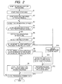
- driving-support processing executed by the driving-support apparatus 101 will be described with reference to the flowchart of Fig. 2 .
- the processing is started e.g. when the engine of the automobile is activated.
- Step S1 the photographing unit 111 starts photographing. Specifically, the photographing unit 111 starts to photograph the face of a driver, and starts supplying the photographed face image to the direction-of-face detection unit 121 and the direction-of-sight line detection unit 122.
- Step S2 the speed-detection unit 112 starts to detect the speed of the automobile, and starts to supply an information piece showing the detected speed to the field-of-view detection unit 123 and the judging unit 124.
- the direction-of-face detection unit 121 detects the orientation of face. Specifically, the direction-of-face detection unit 121 detects the face orientation of the driver based on the face image, and supplies an information piece showing the detected orientation of face to the field-of-view detection unit 123 and the judging unit 124.
- Step S4 the judging unit 124 judges whether or not the orientation of face is within a predetermined range (hereinafter referred to as "face orientation-judging range").
- the face orientation-judging range refers to a range of the orientation of face making a reference to judge whether or not the driver is looking aside.
- the judging unit 124 judges that the driver is looking aside.
- Step S4 When in Step S4 the orientation of face is judged to be within the face orientation-judging range, the processing proceeds to Step S5.
- Step S5 the direction-of-sight line detection unit 122 detects the orientation of sight line.
- the judging unit 124 directs the field-of-view detection unit 123 to detect the field of view of the driver.
- the field-of-view detection unit 123 directs the direction-of-sight line detection unit 122 to detect the sight line orientation of the driver.
- the direction-of-sight line detection unit 122 detects the sight line orientation of the driver based on the face image, and supplies an information piece showing the detected orientation of sight line to the field-of-view detection unit 123.
- the field-of-view detection unit 123 detects the field of view. Specifically, the field-of-view detection unit 123 detects, as a driver's field of view, a predetermined range with respect to the sight line orientation of the driver in a horizontal direction (hereinafter referred to as "field-of-view range").
- Cited Reference 1 (hereinafter referred to as Cited Reference 1) is reported the experimental result that the time required for a driver to recognize the emission light of an LED (Light Emitting Diode) shows no remarkable difference owing to the differences in display position, color and LED diameter when the LED display position is within a range between 20 degrees on the left and 20 degrees on the right with respect to the front direction of the driver, whereas when the display position is beyond the range, it shows a remarkable difference depending on the differences in display position, color and LED diameter.
- LED Light Emitting Diode
- the field-of-view range it is possible as an example of the field-of-view range to set a range of -20 to +20 degrees with respect to the sight line orientation of the driver as the center.
- the breadth of the field-of-view range may be adjusted according to the extent of the difference between the orientation of face and the orientation of sight line. For instance, when the extent of the difference between the face orientation and sight line orientation of the driver in the horizontal direction is 5 degrees or larger, the field-of-view range may be set to a range of -15 to +15 degrees with respect to the sight line orientation of the driver as the center.
- the field-of-view range may be set to a range of -20 to +10 degrees with respect to the sight line orientation of the driver when the driver's sight line strays off the orientation of the face in the left direction in the case where the extent of the difference between the face orientation and sight line orientation of the driver in the horizontal direction is 5 degrees or larger; when the driver's sight line strays off the orientation of the face in the right direction, the field-of-view range may be set to a range of -10 to +20 degrees with respect to the sight line orientation of the driver.
- the breadth of the field-of-view range may be adjusted more finely according to the difference between the orientations of the face and sight line.
- the breadth of the field-of-view range may be adjusted according to the speed of an automobile because the driver's field of view is narrowed with an increase in the speed of an automobile.
- the field-of-view range may be set to: a range of -50 to +50 degrees with respect to the sight line orientation of the driver as the center when the speed of the automobile is 40 km per hour or below; a range of -32 to +32 degrees with respect to the sight line orientation of the driver as the center in the case of 70 km per hour or below; a range of -20 to +20 degrees with respect to the sight line orientation of the driver as the center in the case of 100 km per hour or below; and a range of -10 to +10 degrees with respect to the reference direction as the center in the case of above 100 km per hour.
- the field-of-view detection unit 123 supplies the judging unit 124 with an information piece showing the detected driver's field of view.
- Step S7 the judging unit 124 judges whether or not a range to look carefully is included in the field of view.
- a predetermined range set as the range which the driver should look to carefully while driving is included in the driver's field of view detected by the field-of-view detection unit 123
- the judging unit 124 judges that the range to look carefully is included in the field of view, and the processing proceeds to Step S8.
- a range of -10 to +10 with respect to the reference direction shall be set as the range which the driver should look to carefully while driving.
- Step S8 the judging unit 124 judges whether or not the range to look carefully is located nearer to the vicinity of an end of the field of view. Specifically, when the range to look carefully falls in neither a predetermined range in the right direction with respect to the left end of the driver' s field of view (hereinafter referred to as "left end field-of-view range”), nor a predetermined range in the left direction with respect to the right end of the field of view (hereinafter referred to as "right end field-of-view range”), the judging unit 124 judges that the range to look carefully is not located nearer to the vicinities of the ends of the field of view, and the processing proceeds to Step S9.
- left end field-of-view range a predetermined range in the right direction with respect to the left end of the driver' s field of view
- right end field-of-view range a predetermined range in the left direction with respect to the right end of the field of view
- the left end field-of-view range is defined as a range extending from the left end of the driver' s field of view to 20 degrees in the right direction
- the right end field-of-view range is defined as a range extending from the right end of the driver' s field of view to 20 degrees in the left direction
- Fig. 3 shows examples of orientations of the face and sight line of the driver, in which the broken-line arrow represents a reference direction, i.e. the forward direction of the automobile, the solid-line arrow represents the orientation of the sight line. Also, in Figs. 4 to 7 , to which reference will be made later, the broken-line arrow represents the reference direction, and the solid-line arrow represents the orientation of the sight line.
- a range of -20 to +20 degrees makes the driver's field of view.
- the range to look carefully -10 to +10 degrees, falls in neither a range of -20 to 0 degrees, which is the left end field-of-view range, nor a range of 0 to +20 degrees, which is the right end field-of-view range. Therefore, it is judged that the range to look carefully is not located nearer to the vicinity of an end of the field of view, and the processing proceeds to Step S9.
- Step S9 the judging unit 124 judges that the driver is not looking aside, and the condition is safe.
- the judging unit 124 supplies the car control unit 114 with an information piece showing that the driver is not looking aside and the condition is safe. After that, the processing proceeds to Step S13.
- Step S8 when the range to look carefully falls in at least one of the left end field-of-view range and the right end field-of-view range, the judging unit 124 judges that the range to look carefully is located nearer to the vicinity of an end of the field of view, and the processing proceeds to Step S10.
- a range of -20 to +10 degrees makes the driver's field of view.
- the range to look carefully falls in a range of -10 to +10 degrees, which is the right end field-of-view range, and therefore it is judged that the range to look carefully is located nearer to the vicinity of the right end of the field of view, and the processing proceeds to Step S10.
- a range of -10 to +20 degrees makes the driver's field of view.
- the range to look carefully, -10 to +10 degrees falls in a range of -10 to +10 degrees, which is the left end field-of-view range, and therefore it is judged that the range to look carefully is located nearer to the vicinity of the left end of the driver' s field of view, and the processing proceeds to Step S10.
- Step S10 the judging unit 124 judges that the driver is not looking aside, but the condition is risky.
- the humans' eyesight becomes lower at a point nearer to an end of the field of view. Therefore, when the range to look carefully is located nearer to the vicinity of an end of the driver' s field of view, the judging unit 124 judges that the driver is not looking aside, however the condition is risky because there is a high probability that the range to look carefully is not in sight sufficiently.
- the judging unit 124 supplies the car control unit 114 with an information piece showing that the driver is not looking aside, however the condition is risky. After that, the processing proceeds to Step S12.
- Step S7 when it is judged that the range to look carefully does not fall in the field of view, the processing proceeds to Step S11.
- Step S11 when driver' s face is angled in a direction of 0 degree, and the sight line of the driver is angled in a direction of -20 degrees as shown in Fig. 6 , a range of -35 to -5 degrees makes the driver's field of view. In this case, it is judged that the range to look carefully, -10 to +10 degrees, does not fall in the driver' s field of view, and the processing proceeds to Step S11.
- Step S11 the judging unit 124 judges that the act of looking aside is going on.
- the judging unit 124 supplies the car control unit 114 with an information piece showing that the driver is looking aside.
- Step S4 when it is judged that the orientation of the face is out of the face orientation-judging range, the processing proceeds to Step S11.
- Step S11 regardless of the orientations of the sight line and field of view of the driver, it is judged that the act of looking aside is going on.
- Cited Reference 2 17-20 “ (hereinafter referred to as Cited Reference 2) is reported the experimental result that when the angle of an object that a driver is looking carefully exceeds 20 degrees on the right and left, the angle of the orientation of face is beyond the angle of the ocular movement, and therefore the driver shows a more remarkable tendency to move his or her face.
- the maximum value of the difference between the face orientation and sight line orientation of the driver is 20 degrees
- the sight line orientation of the driver represents a direction on the left of -5 degrees
- the driver's field of view is made a range in a direction on the left of +10 degrees.
- the sight line orientation of the driver represents a direction on the right of +5 degrees
- the driver's field of view is made a range in a direction on the right of -10 degrees.
- the face orientation-judging range it is possible to set a range of -25 to +25 degrees with respect to the reference direction.
- Step S12 the car control unit 114 performs a process to cope with the act of looking aside. For instance, when the driver remains looking aside for a predetermined first time or longer, or when the driver is not looking aside, however a risky condition continues for a second predetermined time or longer, which is longer than the first time, the car control unit 114 makes a display device provided in the automobile display a warning picture to alert the driver, and causes a speaker provided in the automobile to output an alarm to alert the driver.
- Step S13 the driving-support apparatus 101 judges whether or not to terminate the processing. When it is judged that the processing is not terminated, the processing is returned back to Step S3. Until it is judged that the processing is to be terminated in Step S13, the processes in Step S3 to S13 are executed repeatedly.
- Step S13 for instance, when the engine of the automobile is stopped, the driving-support apparatus 101 judges that the processing is to be terminated, and the driving-support processing is terminated.
- a related-art technique can be used as the technique to detect the orientation of face and the orientation of sight line, and the needs for additionally performing a complicated process is eliminated. Therefore, the accuracy of detecting the act of looking aside can be increased readily.
- the example of detecting the act of looking aside by the driver driving a car is shown.
- the invention is also applicable to e.g. detection of the act of looking aside by persons who need to carefully look to a predetermined direction, such as persons driving or operating various types of vehicles e.g. electric railcars, aircrafts and watercraft, persons operating machines including a working machine.
- the time during which the face is faced to outside the face orientation-judging range, or the time during which the condition that a range to look carefully is not included in the field of view continues may be considered.
- the time used for the judgment may be adjusted according to e.g. the speed of the automobile or the orientation of the face or sight line.
- the technique to detect the orientations of face and sight line are not limited to the one which uses an image, and it may be the one which uses e.g. a sensor attached to the head of a driver to detect the orientations.
- the above-described processes in a series may be executed by software as well as hardware.
- a program constituting the software is installed from a medium with the program recorded thereon to a computer incorporated in a dedicated piece of hardware, or a multipurpose personal computer, which can execute various kinds of functions when various kinds of programs are installed thereto, for example.
- Fig. 8 is a block diagram showing an example of the hardware configuration of a computer which executes the series of processes as described above according to the program.
- a CPU Central Processing Unit
- ROM Read Only Memory
- RAM Random Access Memory
- an input-output interface 305 is connected to the bus 304.
- an input unit 306 composed of a keyboard, a mouse, a microphone, etc.
- an output unit 307 composed of a display, a speaker, etc.
- a storage unit 308 composed of a hard disc, a nonvolatile memory, etc.
- a communication unit 309 composed of a network interface, etc.
- a drive 310 for driving a removable medium 311 such as a magnetic disc, an optical disc, a magneto-optical disc or a semiconductor memory.
- the CPU 301 loads the program stored in e.g. the storage unit 308 into the RAM 303 through the input-output interface 305 and the bus 304 and runs the program, whereby the series of processes as described above is performed.
- the program which the computer (CPU 301) runs is recorded on and offered by the removable medium 311, which is a package medium composed of e.g. a magnetic disc (including a flexible disc), an optical disc (CD-ROM (Compact Disc-Read Only Memory), DVD(Digital Versatile Disc), etc.), a magneto-optical disc, or a semiconductor memory, otherwise offered through a wired or wireless transmission medium such as a local area network, the Internet or digital satellite broadcasting.
- a package medium composed of e.g. a magnetic disc (including a flexible disc), an optical disc (CD-ROM (Compact Disc-Read Only Memory), DVD(Digital Versatile Disc), etc.), a magneto-optical disc, or a semiconductor memory, otherwise offered through a wired or wireless transmission medium such as a local area network, the Internet or digital satellite broadcasting.
- the program can be installed to the storage unit 308 through the input-output interface 305 by setting the removable medium 311 in the drive 310. Also, the program can be received with the communication unit 309 through a wired or wireless transmission medium, and installed to the storage unit 308. Otherwise, the program may be previously installed to the ROM 302 or the storage unit 308.
- the program which the computer runs may be a program that processes thereof are performed in time sequence following the order described herein, or a program that the processes are performed in parallel or at a required time such as the time when a call is made.
Landscapes
- Engineering & Computer Science (AREA)
- Physics & Mathematics (AREA)
- Mathematical Physics (AREA)
- General Physics & Mathematics (AREA)
- Emergency Management (AREA)
- Automation & Control Theory (AREA)
- Business, Economics & Management (AREA)
- Transportation (AREA)
- Mechanical Engineering (AREA)
- Traffic Control Systems (AREA)
- Image Processing (AREA)
- Image Analysis (AREA)
- Fittings On The Vehicle Exterior For Carrying Loads, And Devices For Holding Or Mounting Articles (AREA)
Applications Claiming Priority (1)
| Application Number | Priority Date | Filing Date | Title |
|---|---|---|---|
| JP2007175780A JP4946672B2 (ja) | 2007-07-04 | 2007-07-04 | 脇見検出装置および方法、並びに、プログラム |
Publications (2)
| Publication Number | Publication Date |
|---|---|
| EP2012286A2 true EP2012286A2 (de) | 2009-01-07 |
| EP2012286A3 EP2012286A3 (de) | 2010-06-09 |
Family
ID=39884023
Family Applications (1)
| Application Number | Title | Priority Date | Filing Date |
|---|---|---|---|
| EP08104627A Withdrawn EP2012286A3 (de) | 2007-07-04 | 2008-07-03 | Vorrichtung, Verfahren und Programm zur Erkennung einer Abweichung der Blickrichtung |
Country Status (4)
| Country | Link |
|---|---|
| US (1) | US20090009309A1 (de) |
| EP (1) | EP2012286A3 (de) |
| JP (1) | JP4946672B2 (de) |
| CN (1) | CN101336827A (de) |
Cited By (2)
| Publication number | Priority date | Publication date | Assignee | Title |
|---|---|---|---|---|
| EP2357626A1 (de) * | 2010-02-17 | 2011-08-17 | Honeywell International Inc. | Nah-am-Auge-Verfolgung für eine adaptive Operation |
| US10486600B1 (en) * | 2015-09-28 | 2019-11-26 | Apple Inc. | Systems for improving side-mirror functionality of a vehicle |
Families Citing this family (15)
| Publication number | Priority date | Publication date | Assignee | Title |
|---|---|---|---|---|
| JP4760999B1 (ja) * | 2010-10-29 | 2011-08-31 | オムロン株式会社 | 画像処理装置、画像処理方法、および制御プログラム |
| JP4862955B1 (ja) * | 2010-10-29 | 2012-01-25 | オムロン株式会社 | 画像処理装置、画像処理方法、および制御プログラム |
| WO2013051307A1 (ja) * | 2011-10-06 | 2013-04-11 | 本田技研工業株式会社 | 警報装置 |
| TW201501044A (zh) * | 2013-06-24 | 2015-01-01 | Utechzone Co Ltd | 偵測臉部動作以產生訊號的裝置、方法以及電腦可讀取紀錄媒體 |
| TWI510953B (zh) * | 2013-12-20 | 2015-12-01 | Wistron Corp | 身份驗證防僞方法與應用此方法的身份驗證裝置 |
| DE102014008687A1 (de) * | 2014-06-12 | 2015-12-17 | GM Global Technology Operations LLC (n. d. Ges. d. Staates Delaware) | Verfahren zur Darstellung von Fahrzeugumfeldinformationen eines Kraftfahrzeuges |
| JP6372388B2 (ja) * | 2014-06-23 | 2018-08-15 | 株式会社デンソー | ドライバの運転不能状態検出装置 |
| JP6365438B2 (ja) * | 2015-06-25 | 2018-08-01 | マツダ株式会社 | 運転者状態判定方法及びその判定装置 |
| JP2017151606A (ja) * | 2016-02-23 | 2017-08-31 | 株式会社デンソー | 脇見見落とし注意システム及びコンピュータプログラム |
| JP6485405B2 (ja) * | 2016-05-25 | 2019-03-20 | 株式会社デンソー | 安全運転支援装置及び安全運転支援プログラム |
| CN106618580B (zh) * | 2016-12-23 | 2020-09-15 | 北京大学第一医院 | 一种斜视与眼球震颤头位检测方法、装置及系统 |
| US10311726B2 (en) * | 2017-07-21 | 2019-06-04 | Toyota Research Institute, Inc. | Systems and methods for a parallel autonomy interface |
| JP7180067B2 (ja) | 2017-11-06 | 2022-11-30 | 日本電気株式会社 | 運転支援装置 |
| JP6777060B2 (ja) * | 2017-11-15 | 2020-10-28 | オムロン株式会社 | 脇見判定装置、運転支援システム、脇見判定方法及び脇見判定のためのプログラム |
| DE102018127756A1 (de) * | 2017-11-15 | 2019-05-16 | Omron Corporation | Fahrerüberwachungsvorrichtung, verfahren und programm |
Citations (1)
| Publication number | Priority date | Publication date | Assignee | Title |
|---|---|---|---|---|
| JP2003317197A (ja) | 2002-04-26 | 2003-11-07 | Aisin Aw Co Ltd | 警報システム |
Family Cites Families (20)
| Publication number | Priority date | Publication date | Assignee | Title |
|---|---|---|---|---|
| US4953111A (en) * | 1987-02-12 | 1990-08-28 | Omron Tateisi Electronics Co. | Doze detector |
| JPS63222940A (ja) * | 1987-03-11 | 1988-09-16 | Hitachi Ltd | 自動車安全走行支援方式 |
| JPH06150199A (ja) * | 1992-11-13 | 1994-05-31 | Mitsubishi Electric Corp | 車両予防安全装置 |
| JPH06243398A (ja) * | 1993-02-15 | 1994-09-02 | Mitsubishi Electric Corp | 車両予防安全装置 |
| JP3316725B2 (ja) * | 1995-07-06 | 2002-08-19 | 三菱電機株式会社 | 顔画像撮像装置 |
| US6144755A (en) * | 1996-10-11 | 2000-11-07 | Mitsubishi Electric Information Technology Center America, Inc. (Ita) | Method and apparatus for determining poses |
| US5916181A (en) * | 1997-10-24 | 1999-06-29 | Creative Sports Designs, Inc. | Head gear for detecting head motion and providing an indication of head movement |
| US7523956B2 (en) * | 1999-12-23 | 2009-04-28 | Zumpano Bernard J | Inflatable restraint assembly for vehicles |
| US6879969B2 (en) * | 2001-01-21 | 2005-04-12 | Volvo Technological Development Corporation | System and method for real-time recognition of driving patterns |
| JP4882153B2 (ja) * | 2001-02-19 | 2012-02-22 | 日産自動車株式会社 | 車輌用情報出力装置 |
| US6496117B2 (en) * | 2001-03-30 | 2002-12-17 | Koninklijke Philips Electronics N.V. | System for monitoring a driver's attention to driving |
| US6927694B1 (en) * | 2001-08-20 | 2005-08-09 | Research Foundation Of The University Of Central Florida | Algorithm for monitoring head/eye motion for driver alertness with one camera |
| ATE454849T1 (de) * | 2002-10-15 | 2010-01-15 | Volvo Technology Corp | Verfahren für die auswertung der kopf- und augenaktivität einer person |
| JP4300818B2 (ja) * | 2002-11-25 | 2009-07-22 | 日産自動車株式会社 | 車載表示装置および携帯表示装置 |
| JP4204336B2 (ja) * | 2003-01-30 | 2009-01-07 | 富士通株式会社 | 顔の向き検出装置、顔の向き検出方法及びコンピュータプログラム |
| JP4123077B2 (ja) * | 2003-06-27 | 2008-07-23 | 日産自動車株式会社 | 運転者状態検出装置 |
| JP4370915B2 (ja) * | 2004-01-14 | 2009-11-25 | オムロン株式会社 | 車載アプリケーション選択システム及び車載アプリケーション選択装置 |
| US8179435B2 (en) * | 2005-09-28 | 2012-05-15 | Nissan Motor Co., Ltd. | Vehicle surroundings image providing system and method |
| JP4926437B2 (ja) * | 2005-09-28 | 2012-05-09 | 富士重工業株式会社 | 車両の運転支援装置 |
| WO2007145566A1 (en) * | 2006-06-11 | 2007-12-21 | Volvo Technology Corporation | Method and apparatus for determining and analyzing a location of visual interest |
-
2007
- 2007-07-04 JP JP2007175780A patent/JP4946672B2/ja not_active Expired - Fee Related
-
2008
- 2008-07-01 CN CNA2008101284626A patent/CN101336827A/zh active Pending
- 2008-07-02 US US12/167,022 patent/US20090009309A1/en not_active Abandoned
- 2008-07-03 EP EP08104627A patent/EP2012286A3/de not_active Withdrawn
Patent Citations (1)
| Publication number | Priority date | Publication date | Assignee | Title |
|---|---|---|---|---|
| JP2003317197A (ja) | 2002-04-26 | 2003-11-07 | Aisin Aw Co Ltd | 警報システム |
Non-Patent Citations (2)
| Title |
|---|
| HAJIME TAKADA ET AL.: "Collection No. 4-06 of proceedings of Academic lecture meeting in Japan", May 2006, SOCIETY OF AUTOMOTIVE ENGINEERS OF JAPAN, INC., pages: 11 - 16 |
| SATOSHI NAKAGOSHI ET AL.: "Collection No. 58-06 of proceedings of Academic lecture meeting in Japan", May 2006, SOCIETY OF AUTOMOTIVE ENGINEERS OF JAPAN, INC., pages: 17 - 20 |
Cited By (3)
| Publication number | Priority date | Publication date | Assignee | Title |
|---|---|---|---|---|
| EP2357626A1 (de) * | 2010-02-17 | 2011-08-17 | Honeywell International Inc. | Nah-am-Auge-Verfolgung für eine adaptive Operation |
| US8552850B2 (en) | 2010-02-17 | 2013-10-08 | Honeywell International Inc. | Near-to-eye tracking for adaptive operation |
| US10486600B1 (en) * | 2015-09-28 | 2019-11-26 | Apple Inc. | Systems for improving side-mirror functionality of a vehicle |
Also Published As
| Publication number | Publication date |
|---|---|
| JP4946672B2 (ja) | 2012-06-06 |
| US20090009309A1 (en) | 2009-01-08 |
| EP2012286A3 (de) | 2010-06-09 |
| CN101336827A (zh) | 2009-01-07 |
| JP2009015550A (ja) | 2009-01-22 |
Similar Documents
| Publication | Publication Date | Title |
|---|---|---|
| EP2012286A2 (de) | Vorrichtung, Verfahren und Programm zur Erkennung einer Abweichung der Blickrichtung | |
| EP2012285A2 (de) | Vorrichtung, Verfahren und Programm zur Erkennung einer Abweichung der Blickrichtung | |
| US11295143B2 (en) | Information processing apparatus, information processing method, and program | |
| US9888875B2 (en) | Driver monitoring apparatus | |
| US10882536B2 (en) | Autonomous driving control apparatus and method for notifying departure of front vehicle | |
| US20090167516A1 (en) | Look-away detecting device, method and program | |
| CN111699680A (zh) | 行车记录仪、显示控制方法以及程序 | |
| US20190248374A1 (en) | Concentration degree determination device, concentration degree determination method, and program for determining concentration degree | |
| US20210291837A1 (en) | Concentration degree determination device, concentration degree determination method, and program for determining concentration degree | |
| CN115179955A (zh) | 清醒状态判断系统及自动驾驶装置 | |
| JP2021160577A (ja) | 車両制御装置および車両制御方法 | |
| JP2017019419A (ja) | 車輛用ドア開閉制御装置およびドア開閉制御システム、ドア開閉予告システム | |
| US10726728B2 (en) | System and method for controlling movable body | |
| US12272075B2 (en) | Information processing apparatus, information processing method, and storage medium for estimating movement amount of moving object | |
| US20200023863A1 (en) | Concentration degree determination device, concentration degree determination method, and program for determining concentration degree | |
| JP4534789B2 (ja) | 車両用警報装置 | |
| KR20130029985A (ko) | 차선유지 제어장치 및 그 방법 | |
| JP6570302B2 (ja) | 運転支援装置 | |
| CN119343283A (zh) | 用于车辆的驾驶员辅助系统和驾驶员辅助方法 | |
| US9428221B2 (en) | Drive assist control device | |
| JP2018149942A (ja) | 集中度判定装置、集中度判定方法及び集中度判定のためのプログラム | |
| US20240400113A1 (en) | Vehicle control device, vehicle control method and vehicle control computer program | |
| US20230334878A1 (en) | Condition monitoring apparatus and storage medium | |
| JP6722409B2 (ja) | 運転支援装置 | |
| US12340599B2 (en) | Image processing device and image processing method |
Legal Events
| Date | Code | Title | Description |
|---|---|---|---|
| PUAI | Public reference made under article 153(3) epc to a published international application that has entered the european phase |
Free format text: ORIGINAL CODE: 0009012 |
|
| AK | Designated contracting states |
Kind code of ref document: A2 Designated state(s): AT BE BG CH CY CZ DE DK EE ES FI FR GB GR HR HU IE IS IT LI LT LU LV MC MT NL NO PL PT RO SE SI SK TR |
|
| AX | Request for extension of the european patent |
Extension state: AL BA MK RS |
|
| PUAL | Search report despatched |
Free format text: ORIGINAL CODE: 0009013 |
|
| AK | Designated contracting states |
Kind code of ref document: A3 Designated state(s): AT BE BG CH CY CZ DE DK EE ES FI FR GB GR HR HU IE IS IT LI LT LU LV MC MT NL NO PL PT RO SE SI SK TR |
|
| AX | Request for extension of the european patent |
Extension state: AL BA MK RS |
|
| RIC1 | Information provided on ipc code assigned before grant |
Ipc: A61B 5/18 20060101ALI20100503BHEP Ipc: B60K 28/06 20060101ALI20100503BHEP Ipc: G08B 21/06 20060101AFI20081107BHEP |
|
| AKY | No designation fees paid | ||
| REG | Reference to a national code |
Ref country code: DE Ref legal event code: 8566 |
|
| STAA | Information on the status of an ep patent application or granted ep patent |
Free format text: STATUS: THE APPLICATION IS DEEMED TO BE WITHDRAWN |
|
| 18D | Application deemed to be withdrawn |
Effective date: 20101209 |