EP2012163A2 - Objectif de projection avec méchanisme de tilt pour la correction de la courbure de champ - Google Patents
Objectif de projection avec méchanisme de tilt pour la correction de la courbure de champ Download PDFInfo
- Publication number
- EP2012163A2 EP2012163A2 EP08011507A EP08011507A EP2012163A2 EP 2012163 A2 EP2012163 A2 EP 2012163A2 EP 08011507 A EP08011507 A EP 08011507A EP 08011507 A EP08011507 A EP 08011507A EP 2012163 A2 EP2012163 A2 EP 2012163A2
- Authority
- EP
- European Patent Office
- Prior art keywords
- projection
- lens unit
- optical axis
- projection lens
- image
- Prior art date
- Legal status (The legal status is an assumption and is not a legal conclusion. Google has not performed a legal analysis and makes no representation as to the accuracy of the status listed.)
- Granted
Links
- 238000012937 correction Methods 0.000 title claims abstract description 17
- 230000007246 mechanism Effects 0.000 title claims abstract description 17
- 230000003287 optical effect Effects 0.000 claims abstract description 58
- 230000004907 flux Effects 0.000 claims abstract description 14
- 238000013459 approach Methods 0.000 claims description 2
- 238000006243 chemical reaction Methods 0.000 claims 1
- 238000000034 method Methods 0.000 description 9
- 239000013256 coordination polymer Substances 0.000 description 4
- 230000006866 deterioration Effects 0.000 description 3
- 230000000694 effects Effects 0.000 description 3
- 239000004973 liquid crystal related substance Substances 0.000 description 3
- 230000002093 peripheral effect Effects 0.000 description 3
- 230000009467 reduction Effects 0.000 description 3
- 230000004075 alteration Effects 0.000 description 2
- 230000009471 action Effects 0.000 description 1
- 230000015572 biosynthetic process Effects 0.000 description 1
- 230000008859 change Effects 0.000 description 1
- 238000011161 development Methods 0.000 description 1
- 238000006073 displacement reaction Methods 0.000 description 1
- 238000004519 manufacturing process Methods 0.000 description 1
- 238000012986 modification Methods 0.000 description 1
- 230000004048 modification Effects 0.000 description 1
Images



Classifications
-
- G—PHYSICS
- G02—OPTICS
- G02B—OPTICAL ELEMENTS, SYSTEMS OR APPARATUS
- G02B13/00—Optical objectives specially designed for the purposes specified below
- G02B13/16—Optical objectives specially designed for the purposes specified below for use in conjunction with image converters or intensifiers, or for use with projectors, e.g. objectives for projection TV
-
- G—PHYSICS
- G02—OPTICS
- G02B—OPTICAL ELEMENTS, SYSTEMS OR APPARATUS
- G02B27/00—Optical systems or apparatus not provided for by any of the groups G02B1/00 - G02B26/00, G02B30/00
- G02B27/0025—Optical systems or apparatus not provided for by any of the groups G02B1/00 - G02B26/00, G02B30/00 for optical correction, e.g. distorsion, aberration
- G02B27/0068—Optical systems or apparatus not provided for by any of the groups G02B1/00 - G02B26/00, G02B30/00 for optical correction, e.g. distorsion, aberration having means for controlling the degree of correction, e.g. using phase modulators, movable elements
Definitions
- the present invention relates to a projection lens used in optical apparatuses such as an image projection apparatus.
- a projection lens used in an image projection apparatus such as a projector requires a long back focus to avoid interference of the projection lens with a color separating/combining optical system.
- the projection lens for the projector therefore often adopts a so-called retrofocus type lens configuration including a stronger negative refractive power at a position closer to a screen than an aperture stop.
- the retrofocus type lens is characterized in that, mainly from its asymmetry, field curvature is easily caused due to distance variations, in other words image quality is easily changed due to variation of its projection distance.
- the field angle of the projection lens is increased and thereby the characteristic described above becomes more notable.
- there is less tolerance for influences of variation of the field curvature due to the distance variation because of a higher resolution of an image-forming element such as a liquid-crystal panel.
- the present invention in its first aspect provides a projection lens as specified in claims 1 to 5 and 8.
- the present invention in its second aspect provides a projection lens as specified in claims 6 to 8.
- the present invention in its third aspect provides an image projection apparatus as specified in claim 9.
- the present invention in its fourth aspect provides an optical apparatus as specified in claim 10.
- FIG. 1 is a schematic view showing the configuration of a projection lens that is an embodiment of the present invention.
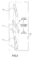
- FIG. 2 is a development view showing the configuration of a cam mechanism in the embodiment.
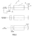
- FIG. 3 is an explanatory view of focusing and variations of field curvature.
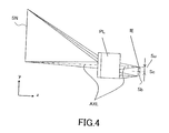
- FIG. 4 is a schematic view showing the configuration of a projector including the projection lens of the embodiment.
- FIG. 5 is an enlarged view of the field curvature.
- FIG. 6 is an explanatory view showing tilt of an image plane caused by tilting a first lens unit in the embodiment.
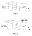
- FIG. 7A shows field curvatures caused at projection surfaces whose distances are different from each other when there is no field curvature correction mechanism.
- FIG. 7B shows field curvatures caused at projection surfaces whose distances are different from each other when there is a field curvature correction mechanism in the embodiment.
- FIG. 1 schematically shows a projection lens for projectors, which is an embodiment of the present invention.
- the embodiment will be explained using a so-called inverse projection method in which light fluxes emitted from respective points on a projection surface such as a flat screen form images on an image-forming element such as a liquid-crystal panel through the projection lens.
- a screen side (a magnification side or a magnification conjugate side) is defined as an object side
- an image-forming element side (a reduction side or a reduction conjugate side) is defined as an image plane side
- a surface formed by image formation of the light fluxes emitted from the respective points on the projection surface is referred to as an image plane.
- a surface where a flat image plane is to be formed under normal conditions is referred to as a predetermined image plane.
- the projection lens causes the image-forming element and the projection surface (screen) to have a conjugate relationship to form an image of the image-forming element on the projection surface.
- the image-forming element side corresponds to an object side.
- the light fluxes emitted from the respective points on the image-forming element form the image plane on the projection surface (hereinafter referred to as the screen) that is the predetermined image plane.
- the screen side has the same meaning as that of the projection surface side.
- reference character I denotes a first lens unit that is movable in an optical axis direction and constitutes a part of the projection lens PL.
- the first lens unit I is a negative lens unit (optical unit) having a negative refractive power (negative optical power).
- Reference character II denotes a second lens unit that constitutes another part of the projection lens PL and is disposed closer to the image plane (side) (actually disposed closer to the screen (side)) than the first lens unit I.
- the second lens unit II is constituted by at least one lens unit (more preferably, by plural lens units).
- Reference character IE denotes an image-forming element such as a liquid-crystal panel that is disposed at the predetermined image plane.
- the image-forming element forms an original image corresponding to image signals from an image supply apparatus such as a personal computer, a DVD player or a television tuner, not shown.
- Reference character AXL denotes an optical axis of the projection lens PL.
- the horizontal direction in the drawing is defined as a z-axis direction, and a direction from the left toward the right that is a direction of the inverse projection is defined as a positive direction in the z-axis direction.
- the vertical direction in the drawing is defined as a y-axis direction, and a direction from the bottom toward the top is a positive direction in the y-axis direction.
- the projection lens PL of this embodiment in which the first lens unit I closest to the screen (disposed at the most screen side) having a negative refractive power is a retrofocus type projection lens.
- focusing is performed by moving the first lens unit I in the optical axis direction. Specifically, when projecting an image onto a screen whose distance is shorter than a reference projection distance (shown as REFERENCE DISTANCE in the drawing), the first lens unit I is moved to the screen side (moved outward). When projecting an image onto a screen whose distance is longer than the reference projection distance, the first lens unit I is moved to the image-forming element side (moved inward).
- FIG. 3 shows this schematically. Also, FIG. 3 schematically shows field curvature FC generated in the focusing.
- a peripheral part of the image plane in the direction orthogonal to the optical axis AXL is called merely a "peripheral image part”
- a shift of the peripheral image part to the positive (+) direction is referred to as “field curvature generated in an over direction”
- a shift thereof to a negative (-) direction is referred to as "field curvature generated in an under direction”.
- the field curvature FC is generated in the over direction when the first lens unit I having a negative refractive power is moved outward, and the field curvature FC is generated in the under direction when the first lens unit I is moved inward.
- the first lens unit I is moved outward for focusing to a closer position to generate the field curvature in the over direction and moved inward for focusing to a farther position to generate the field curvature in the under direction.
- the y coordinates of an upper edge and a lower edge of the image-forming element IE are denoted by Su and Sb, respectively.
- the projection lens PL projects a light flux from the image-forming element (object) IE located at one side (lower side) in the direction orthogonal to the optical axis AXL onto a screen SN located at another side (upper side) in that direction.
- the projection lens PL projects the light flux from the image-forming element IE located at the lower side with respect to the optical axis AXL onto the screen SN located at the upper side with respect to the optical axis AXL.
- FIG. 5 schematically shows a state where the field curvature FC is generated on the image-forming element IE, in the inverse projection method.
- the amount of the field curvature at an arbitrary y coordinate on the image plane is defined as ⁇ W(y).
- the over direction is shown by ⁇ W > 0, and the under direction is shown by ⁇ W ⁇ 0.
- a sign of the tilt amount ⁇ of the image plane is positive in the over direction, and shown by an arrow in FIG. 5 .
- the projection lens PL of this embodiment causes the first lens unit I serving as a focusing lens to tilt with respect to the optical axis AXL (in other words with respect to the second lens unit II) to generate field tilt according to the tilt direction of the first lens unit I.
- the tilt direction of the first lens unit I is a direction in which the field tilt is generated (an image plane is tilted) in a direction opposite to that of the field curvature on the screen SN.
- tilting the first lens unit I in a state for example, where the field curvature is generated in the over direction as shown in FIG. 5 makes it possible to cause a straight line tilted by an angle of ⁇ with respect to a y-axis to be parallel (includes a case that can be regarded as parallel) or near parallel to the y-axis.
- This makes it possible to cause an approximately flat object surface and an approximately flat image plane to have a substantially conjugate relationship even when the field curvature is generated, thereby enabling projection of an in-focus image onto the screen SN.
- FIG. 6 schematically shows the field tilt generated by tilting the first lens unit I. While the field curvature FC is generated symmetrically with respect to the optical axis AXL in the vertical direction as shown in FIG.3 , the field tilt FT is generated asymmetrically in the vertical direction.
- the explanation for the field tilt FT in this embodiment is related to the lower half area of the effective image circle which is used in actually image projection.
- a direction of rotation (tilt) shown with reference character CW in FIG. 6 is called a clockwise direction, and a direction of rotation shown with reference character CCW is called a counterclockwise direction.
- the rotation directions CW and CCW are defined for the case where the right side is the reduction conjugate side (image-forming element side) and the left side is the magnification conjugate side (projection surface side). Said another way, the rotation directions CW and CCW are directions when the lower half area of the effective image circle is used in a conjugate plane on the right side and an upper half area thereof is used in a conjugate plane of the left side. Therefore, if the left and right sides are reversed, the rotation directions CW and CCW are also reversed.
- the first lens unit I disposed closest to the screen (at the most-screen side) has a negative refractive power. Tilting the first lens unit I in the clockwise (CW) direction generates the field tilt FT in the over direction, and tilting it in the counterclockwise (CCW) direction generates the field tilt FT in the under direction.
- the tilt amount D of the first lens unit I in the clockwise direction is a positive amount
- the angle ⁇ of the field tilt in the over direction is a positive angle, similarly to the tilt amount ⁇ of the image plane.
- A represents an arbitrary fine adjustment coefficient and is a positive value for adequate fine adjustment depending on the shape of the field curvature for individual projection lenses.
- an adequate tilt amount D of the first lens unit I can be obtained by adjusting the coefficient A in the range of: 0.5 ⁇ A ⁇ 2.
- the tilt amount D of the first lens unit I satisfy the following condition: ⁇ / 2 ⁇ ⁇ ⁇ D ⁇ 2 ⁇ ⁇ / ⁇
- condition (2) is preferred to be satisfied, but the condition (2) is not necessarily a condition that must be satisfied.
- the direction of the field curvature is changed by the inward and outward movements of the first lens unit I from a position corresponding to the reference projection distance as described above. However, the amount of the field curvature is changed depending on the inward and outward movement amounts of the first lens unit I.
- this embodiment changes the tilt amount and the tilt direction of the first lens unit I with respect to the optical axis AXL depending on the position of the first lens unit I in the optical axis direction.
- the embodiment employs a cam mechanism, for example.
- FIG. 2 shows a cam barrel CB that constitutes a cam mechanism and is developed in a circumferential direction of the projection lens.
- Three cams (cam grooves) C1, C2, and C3 are formed at three locations on the cam barrel CB in its circumferential direction that corresponds to the top, lower right and lower left of the actual projection lens.
- Cam pins CP provided to a lens holding member, not shown, which holds the first lens unit I engage with the cams C1, C2, and C3.
- an inclination angle of the top cam C1 is set to be larger than those of the other cams C2 and C3. Therefore, an entire lift amount L1 in the optical axis direction obtained by the movement of the cam pin CP between both ends of the cam C1 is larger than an entire lift amount L2 obtained by the movement of the cam pins CP between both ends of the other cams C2 and C3.
- the entire lift amount can also be a movement amount of the cam pin CP in the optical axis direction when a focus state is changed from an infinity (farthest distance) in-focus state to a closest distance in-focus state (when the first lens unit I is moved). In further other words, this also is a length of the cam groove in the optical axis direction.
- the entire lift amount of one of the cams C1, C2, and C3 may be smaller than that of the other two cams.
- This configuration can tilt the first lens unit I in the counterclockwise (CCW) direction when the first lens unit I is moved outward (when the projection lens is focused to a closer distance).
- This configuration also can tilt the first lens unit I in the clockwise (CW) direction when the first lens unit I is moved inward (when the projection lens is focused to a farther distance).
- the inclination angle of the cam C1 can be calculated using the above expression (1).
- this embodiment sets the entire lift amount of at least one of the plural cams formed at the plural locations in the circumference direction of the first lens unit I to be different from the entire lift amounts of the other cams. This enables control of the tilt direction and tilt amount of the first lens unit I according to the position of the first lens unit I in the optical axis direction, that is, according to the projection distance, with a simple configuration.
- the number of the cams can be other than three.
- FIG. 2 shows a case where each cam is formed as a straight cam.
- each cam may be formed as a nonlinear cam to enable fine adjustment of the tilt amount of the first lens unit I according to the inward and outward movement amounts thereof.
- FIGS. 7A and 7B show a correction effect of the field curvature attained on an actual screen using the configuration described above.
- the same reference characters are applied to the elements identical to those shown in FIGS. 1 to 6 .
- reference character V denotes projection surfaces orthogonal to the optical axis AXL of the projection lens PL which are disposed at positions of different projection distances.
- FIG. 7A shows field curvature generated at each projection surface V when the projection lens PL does not use the correction mechanism for the field curvature (tilt mechanism for the first lens unit I) described in this embodiment.
- FIG. 7B shows field curvature generated at each projection surface V when the projection lens PL uses the correction mechanism.
- the projection lens PL projects the light flux from the image-forming element IE located at the lower side with respect to the optical axis AXL onto the projection surface V located at the upper side with respect to the optical axis AXL.
- An image plane (actual projection image plane on which an actual projected image is formed) on the upper side with respect to the optical axis AXL is shown with a solid line, and an image plane, which is not actually formed, on the lower side with respect to the optical axis AXL is shown with a dotted line.
- this embodiment can achieve a good correction effect for the field curvature shown in FIG. 7B by tilting the first lens unit I as described below, with respect to the optical axis AXL (the second lens unit II).
- This embodiment tilts the first lens unit I with respect to the optical axis AXL so that the field tilt is generated in a direction shown by an arrow B opposite to the direction of the field curvature at the projection surface V.
- this embodiment tilts the first lens unit I in a direction in which a part P of the actual projection image plane approaches a plane (projection surface V) orthogonal to the optical axis AXL, the part P being a part where the amount of the field curvature is largest in the actual projection image plane when the first lens unit I is not tilted with respect to the optical axis AXL.
- the width (amount) of the field curvature in the optical axis direction is smaller in the case shown in FIG. 7B where the first lens unit I is tilted.
- the projection lens (and the projector) of this embodiment can project images with reducing image quality deterioration caused due to the field curvature and image quality variation due to change of the projection distance.
- the projection lens of the present embodiment includes a negative lens unit that has a negative refractive power and is constituted by at least one lens, the negative lens unit being disposed closest to the projection surface (disposed at the most projection surface side, most screen side or most magnification side). Further, when the focusing (adjusting the focal length) is performed, the negative lens unit is moved in the optical axis direction. To reduce deterioration of image quality such as defocusing caused by variation of aberrations (mainly variation of field curvature) generated during the focusing, the negative lens unit is moved in the optical axis direction and the tilt of the negative lens unit with respect to the optical axis is changed. Specifically, the tilt of the negative lens unit is changed in a direction that can reduce negative influences caused by the variation of aberrations.
- the tilt angle of the negative lens unit with respect to the optical axis be gradually changed in one direction. Furthermore, it is also preferred that the tilt direction of the negative lens unit with respect to the optical axis in the farthest distance in-focus state be opposite to that in the closest distance in-focus state. It is also acceptable that only the tilt angle of the negative lens unit is changed in the same tilt direction.
- the projection lens is realized which can reduce variation of image quality associated with variations of the field curvature and projection distance with a simple configuration that causes the negative lens unit to tilt independently. Therefore, an image projection apparatus is realized which can project good quality images regardless of the projection distance.
- the above embodiment described the case where the projection lens is shifted upward with respect to the image-forming element.
- the above embodiment described the case where the projection lens is shifted upward and fixed with respect to the image-forming element.
- a field curvature correction method similar to that in the above embodiment can be used for a projector in which a projection lens is movable to be shifted with respected to the image-forming element.
- a lens unit to be tilted may be a negative lens unit disposed at a position other than that closest to the screen.
- the above embodiment described a projector.
- an image-pickup element that photoelectrically converts a light flux from a subject (object) is placed at a predetermined image plane instead of the image-forming element, a field curvature correction effect similar to that described in the above embodiment can be obtained in optical apparatuses other than the projector, such as an image-pickup apparatus (camera) and an interchangeable lens.
- the image-pickup element includes a CCD sensor and a CMOS sensor.
Landscapes
- Physics & Mathematics (AREA)
- General Physics & Mathematics (AREA)
- Optics & Photonics (AREA)
- Lenses (AREA)
- Projection Apparatus (AREA)
Applications Claiming Priority (1)
| Application Number | Priority Date | Filing Date | Title |
|---|---|---|---|
| JP2007175065A JP5063224B2 (ja) | 2007-07-03 | 2007-07-03 | 投射レンズ及び画像投射装置 |
Publications (3)
| Publication Number | Publication Date |
|---|---|
| EP2012163A2 true EP2012163A2 (fr) | 2009-01-07 |
| EP2012163A3 EP2012163A3 (fr) | 2009-03-04 |
| EP2012163B1 EP2012163B1 (fr) | 2011-10-19 |
Family
ID=39719826
Family Applications (1)
| Application Number | Title | Priority Date | Filing Date |
|---|---|---|---|
| EP08011507A Not-in-force EP2012163B1 (fr) | 2007-07-03 | 2008-06-25 | Objectif de projection avec méchanisme de tilt pour la correction de la courbure de champ |
Country Status (4)
| Country | Link |
|---|---|
| US (1) | US7830604B2 (fr) |
| EP (1) | EP2012163B1 (fr) |
| JP (1) | JP5063224B2 (fr) |
| CN (2) | CN101339286B (fr) |
Cited By (1)
| Publication number | Priority date | Publication date | Assignee | Title |
|---|---|---|---|---|
| US11513307B2 (en) | 2018-01-29 | 2022-11-29 | Canon Kabushiki Kaisha | Projection lens and projection display apparatus using the same |
Families Citing this family (7)
| Publication number | Priority date | Publication date | Assignee | Title |
|---|---|---|---|---|
| CN101688341A (zh) * | 2007-06-26 | 2010-03-31 | 出光兴产株式会社 | 弹性无纺布、其制造方法和使用了该弹性无纺布的纤维制品 |
| JP5428885B2 (ja) * | 2010-01-18 | 2014-02-26 | セイコーエプソン株式会社 | プロジェクター |
| WO2013080953A1 (fr) * | 2011-12-01 | 2013-06-06 | 三菱電機株式会社 | Système optique de projection et dispositif d'affichage d'image à projection |
| WO2014133455A1 (fr) | 2013-02-28 | 2014-09-04 | Heptagon Micro Optics Pte. Ltd. | Mesure de points focaux et d'autres caractéristiques dans des systèmes optiques |
| CN103257511B (zh) * | 2013-04-27 | 2016-01-20 | 宁波舜宇光电信息有限公司 | 一种基于镜头场曲的自动对焦方法 |
| JP6991797B2 (ja) * | 2016-10-11 | 2022-01-13 | キヤノン株式会社 | レンズ装置およびこれを用いた画像投射装置 |
| JP7080701B2 (ja) * | 2018-04-10 | 2022-06-06 | キヤノン株式会社 | 画像投射装置およびプログラム |
Citations (4)
| Publication number | Priority date | Publication date | Assignee | Title |
|---|---|---|---|---|
| JPH0235406A (ja) | 1988-07-26 | 1990-02-06 | Canon Inc | 防振機能を有した変倍光学系 |
| US5592331A (en) | 1995-01-18 | 1997-01-07 | Eastcott; John | Optical adapter for controlling the angle of the plane of focus |
| US5617159A (en) | 1994-12-05 | 1997-04-01 | Nikon Corporation | Image blur suppression device with inertial pendulum system for a camera |
| US20030103266A1 (en) | 2001-11-05 | 2003-06-05 | Ken Wada | Projection optical system and projection apparatus using the same |
Family Cites Families (12)
| Publication number | Priority date | Publication date | Assignee | Title |
|---|---|---|---|---|
| DE2905928A1 (de) * | 1979-02-16 | 1980-08-28 | Fichtel & Sachs Ag | Hydropneumatischer zweirohrschwingungsdaempfer mit entlueftungsventil |
| US5270857A (en) * | 1987-10-30 | 1993-12-14 | Canon Kabushiki Kaisha | Optical system for stabilizing an image |
| US5583694A (en) * | 1992-07-14 | 1996-12-10 | Nippon Telegraph And Telephone Corporation | Optical element and optical axis displacement device using the same |
| US5659424A (en) * | 1993-05-25 | 1997-08-19 | Hitachi, Ltd. | Projecting lens and image display device |
| KR100220674B1 (ko) * | 1994-01-18 | 1999-09-15 | 전주범 | 투사형 화상표시장치 |
| JP3495860B2 (ja) * | 1996-11-01 | 2004-02-09 | キヤノン株式会社 | 偏心光学系及びそれを用いた投影装置 |
| EP1075150A3 (fr) * | 1999-07-31 | 2005-04-27 | Lg Electronics Inc. | Système de lentilles de projection |
| JP3755525B2 (ja) * | 2003-09-11 | 2006-03-15 | コニカミノルタオプト株式会社 | 投影光学系および映像投影装置 |
| US7265917B2 (en) * | 2003-12-23 | 2007-09-04 | Carl Zeiss Smt Ag | Replacement apparatus for an optical element |
| JP2005283672A (ja) * | 2004-03-26 | 2005-10-13 | Canon Inc | レンズ装置および画像投射装置 |
| JP2005352407A (ja) | 2004-06-14 | 2005-12-22 | Fujinon Corp | 投映レンズ鏡筒 |
| JP2007121611A (ja) * | 2005-10-27 | 2007-05-17 | Sony Corp | ズームレンズ及び撮像装置 |
-
2007
- 2007-07-03 JP JP2007175065A patent/JP5063224B2/ja not_active Expired - Fee Related
-
2008
- 2008-06-25 EP EP08011507A patent/EP2012163B1/fr not_active Not-in-force
- 2008-06-27 US US12/147,626 patent/US7830604B2/en not_active Expired - Fee Related
- 2008-07-03 CN CN2008101357307A patent/CN101339286B/zh not_active Expired - Fee Related
- 2008-07-03 CN CN201210028219.3A patent/CN102565998B/zh not_active Expired - Fee Related
Patent Citations (4)
| Publication number | Priority date | Publication date | Assignee | Title |
|---|---|---|---|---|
| JPH0235406A (ja) | 1988-07-26 | 1990-02-06 | Canon Inc | 防振機能を有した変倍光学系 |
| US5617159A (en) | 1994-12-05 | 1997-04-01 | Nikon Corporation | Image blur suppression device with inertial pendulum system for a camera |
| US5592331A (en) | 1995-01-18 | 1997-01-07 | Eastcott; John | Optical adapter for controlling the angle of the plane of focus |
| US20030103266A1 (en) | 2001-11-05 | 2003-06-05 | Ken Wada | Projection optical system and projection apparatus using the same |
Cited By (1)
| Publication number | Priority date | Publication date | Assignee | Title |
|---|---|---|---|---|
| US11513307B2 (en) | 2018-01-29 | 2022-11-29 | Canon Kabushiki Kaisha | Projection lens and projection display apparatus using the same |
Also Published As
| Publication number | Publication date |
|---|---|
| US20090009878A1 (en) | 2009-01-08 |
| CN102565998B (zh) | 2016-03-16 |
| US7830604B2 (en) | 2010-11-09 |
| JP5063224B2 (ja) | 2012-10-31 |
| EP2012163A3 (fr) | 2009-03-04 |
| JP2009014905A (ja) | 2009-01-22 |
| CN102565998A (zh) | 2012-07-11 |
| CN101339286A (zh) | 2009-01-07 |
| EP2012163B1 (fr) | 2011-10-19 |
| CN101339286B (zh) | 2012-10-10 |
Similar Documents
| Publication | Publication Date | Title |
|---|---|---|
| EP2012163B1 (fr) | Objectif de projection avec méchanisme de tilt pour la correction de la courbure de champ | |
| US7009779B2 (en) | Macro lens | |
| TWI678587B (zh) | 雙攝像設備 | |
| CN101165532B (zh) | 投射型显示装置 | |
| US10012815B2 (en) | Projection optical system and projection type display apparatus using the same | |
| US9201227B2 (en) | Optical system and image projecting apparatus using the same | |
| US20100053737A1 (en) | Variable magnification optical system and projector | |
| JP5571512B2 (ja) | 投射結像光学系およびプロジェクタ装置 | |
| JP2018109755A (ja) | 固定焦点レンズ | |
| JP6221266B2 (ja) | 投射光学系と画像表示装置 | |
| JP2007304290A (ja) | 投影用ズームレンズおよび投写型表示装置 | |
| JP2979844B2 (ja) | 調整機構を有した撮像装置 | |
| JP2005004041A (ja) | 撮影レンズ | |
| JP4822005B2 (ja) | 不連続な面を有する光学素子を含む結像光学系 | |
| TW201642047A (zh) | 曝光裝置 | |
| JP2012215746A5 (fr) | ||
| JP2015132723A (ja) | 投射光学系および画像表示装置 | |
| CN115980968B (zh) | 光学镜头模组及投影系统 | |
| JP7779722B2 (ja) | 光学系 | |
| JP2008249871A (ja) | 広角プロジェクタ | |
| JP2006276656A (ja) | プロジェクタ | |
| CN118671984A (zh) | 一种光学调整系统及靶标 | |
| JPH04253042A (ja) | シフトズームレンズ系 | |
| WO2025018307A1 (fr) | Système optique de formation d'image, dispositif d'affichage de type à projection et dispositif d'imagerie | |
| JPH0694972A (ja) | トリミングに連動した焦点調節方式 |
Legal Events
| Date | Code | Title | Description |
|---|---|---|---|
| PUAI | Public reference made under article 153(3) epc to a published international application that has entered the european phase |
Free format text: ORIGINAL CODE: 0009012 |
|
| AK | Designated contracting states |
Kind code of ref document: A2 Designated state(s): AT BE BG CH CY CZ DE DK EE ES FI FR GB GR HR HU IE IS IT LI LT LU LV MC MT NL NO PL PT RO SE SI SK TR |
|
| AX | Request for extension of the european patent |
Extension state: AL BA MK RS |
|
| PUAL | Search report despatched |
Free format text: ORIGINAL CODE: 0009013 |
|
| AK | Designated contracting states |
Kind code of ref document: A3 Designated state(s): AT BE BG CH CY CZ DE DK EE ES FI FR GB GR HR HU IE IS IT LI LT LU LV MC MT NL NO PL PT RO SE SI SK TR |
|
| AX | Request for extension of the european patent |
Extension state: AL BA MK RS |
|
| 17Q | First examination report despatched |
Effective date: 20090921 |
|
| 17P | Request for examination filed |
Effective date: 20090904 |
|
| AKX | Designation fees paid |
Designated state(s): DE ES FR GB IT NL |
|
| GRAP | Despatch of communication of intention to grant a patent |
Free format text: ORIGINAL CODE: EPIDOSNIGR1 |
|
| GRAS | Grant fee paid |
Free format text: ORIGINAL CODE: EPIDOSNIGR3 |
|
| GRAA | (expected) grant |
Free format text: ORIGINAL CODE: 0009210 |
|
| RIN1 | Information on inventor provided before grant (corrected) |
Inventor name: INOKO, KAZUHIROC/O CANON KABUSHIKI KAISHA |
|
| AK | Designated contracting states |
Kind code of ref document: B1 Designated state(s): DE ES FR GB IT NL |
|
| REG | Reference to a national code |
Ref country code: GB Ref legal event code: FG4D |
|
| REG | Reference to a national code |
Ref country code: DE Ref legal event code: R096 Ref document number: 602008010531 Country of ref document: DE Effective date: 20111215 |
|
| REG | Reference to a national code |
Ref country code: NL Ref legal event code: VDEP Effective date: 20111019 |
|
| PG25 | Lapsed in a contracting state [announced via postgrant information from national office to epo] |
Ref country code: NL Free format text: LAPSE BECAUSE OF FAILURE TO SUBMIT A TRANSLATION OF THE DESCRIPTION OR TO PAY THE FEE WITHIN THE PRESCRIBED TIME-LIMIT Effective date: 20111019 |
|
| PLBE | No opposition filed within time limit |
Free format text: ORIGINAL CODE: 0009261 |
|
| STAA | Information on the status of an ep patent application or granted ep patent |
Free format text: STATUS: NO OPPOSITION FILED WITHIN TIME LIMIT |
|
| PG25 | Lapsed in a contracting state [announced via postgrant information from national office to epo] |
Ref country code: IT Free format text: LAPSE BECAUSE OF FAILURE TO SUBMIT A TRANSLATION OF THE DESCRIPTION OR TO PAY THE FEE WITHIN THE PRESCRIBED TIME-LIMIT Effective date: 20111019 |
|
| 26N | No opposition filed |
Effective date: 20120720 |
|
| REG | Reference to a national code |
Ref country code: DE Ref legal event code: R097 Ref document number: 602008010531 Country of ref document: DE Effective date: 20120720 |
|
| REG | Reference to a national code |
Ref country code: FR Ref legal event code: ST Effective date: 20130228 |
|
| PG25 | Lapsed in a contracting state [announced via postgrant information from national office to epo] |
Ref country code: FR Free format text: LAPSE BECAUSE OF NON-PAYMENT OF DUE FEES Effective date: 20120702 |
|
| PG25 | Lapsed in a contracting state [announced via postgrant information from national office to epo] |
Ref country code: ES Free format text: LAPSE BECAUSE OF FAILURE TO SUBMIT A TRANSLATION OF THE DESCRIPTION OR TO PAY THE FEE WITHIN THE PRESCRIBED TIME-LIMIT Effective date: 20120130 |
|
| PGFP | Annual fee paid to national office [announced via postgrant information from national office to epo] |
Ref country code: GB Payment date: 20170614 Year of fee payment: 10 |
|
| PGFP | Annual fee paid to national office [announced via postgrant information from national office to epo] |
Ref country code: DE Payment date: 20170630 Year of fee payment: 10 |
|
| REG | Reference to a national code |
Ref country code: DE Ref legal event code: R119 Ref document number: 602008010531 Country of ref document: DE |
|
| GBPC | Gb: european patent ceased through non-payment of renewal fee |
Effective date: 20180625 |
|
| PG25 | Lapsed in a contracting state [announced via postgrant information from national office to epo] |
Ref country code: GB Free format text: LAPSE BECAUSE OF NON-PAYMENT OF DUE FEES Effective date: 20180625 Ref country code: DE Free format text: LAPSE BECAUSE OF NON-PAYMENT OF DUE FEES Effective date: 20190101 |