EP2011973B1 - Kipphebel - Google Patents
Kipphebel Download PDFInfo
- Publication number
- EP2011973B1 EP2011973B1 EP08011527A EP08011527A EP2011973B1 EP 2011973 B1 EP2011973 B1 EP 2011973B1 EP 08011527 A EP08011527 A EP 08011527A EP 08011527 A EP08011527 A EP 08011527A EP 2011973 B1 EP2011973 B1 EP 2011973B1
- Authority
- EP
- European Patent Office
- Prior art keywords
- rocker arm
- cam
- roller
- washers
- sidewalls
- Prior art date
- Legal status (The legal status is an assumption and is not a legal conclusion. Google has not performed a legal analysis and makes no representation as to the accuracy of the status listed.)
- Not-in-force
Links
- 239000002184 metal Substances 0.000 claims description 5
- 230000002093 peripheral effect Effects 0.000 description 5
- 238000010276 construction Methods 0.000 description 1
- 230000000994 depressogenic effect Effects 0.000 description 1
- 238000004080 punching Methods 0.000 description 1
- 238000000926 separation method Methods 0.000 description 1
Images


Classifications
-
- F—MECHANICAL ENGINEERING; LIGHTING; HEATING; WEAPONS; BLASTING
- F01—MACHINES OR ENGINES IN GENERAL; ENGINE PLANTS IN GENERAL; STEAM ENGINES
- F01L—CYCLICALLY OPERATING VALVES FOR MACHINES OR ENGINES
- F01L1/00—Valve-gear or valve arrangements, e.g. lift-valve gear
- F01L1/12—Transmitting gear between valve drive and valve
- F01L1/18—Rocking arms or levers
- F01L1/181—Centre pivot rocking arms
-
- F—MECHANICAL ENGINEERING; LIGHTING; HEATING; WEAPONS; BLASTING
- F01—MACHINES OR ENGINES IN GENERAL; ENGINE PLANTS IN GENERAL; STEAM ENGINES
- F01L—CYCLICALLY OPERATING VALVES FOR MACHINES OR ENGINES
- F01L1/00—Valve-gear or valve arrangements, e.g. lift-valve gear
- F01L1/02—Valve drive
- F01L1/04—Valve drive by means of cams, camshafts, cam discs, eccentrics or the like
- F01L1/047—Camshafts
-
- F—MECHANICAL ENGINEERING; LIGHTING; HEATING; WEAPONS; BLASTING
- F01—MACHINES OR ENGINES IN GENERAL; ENGINE PLANTS IN GENERAL; STEAM ENGINES
- F01L—CYCLICALLY OPERATING VALVES FOR MACHINES OR ENGINES
- F01L1/00—Valve-gear or valve arrangements, e.g. lift-valve gear
- F01L1/12—Transmitting gear between valve drive and valve
- F01L1/18—Rocking arms or levers
- F01L1/185—Overhead end-pivot rocking arms
Definitions
- the present invention relates to a rocker arm that transmits driving force for opening and closing an engine valve.
- rocker arm is disclosed in Japanese Unexamined Patent Application Publication 2001-205378 .
- the rocker arm is formed by punching a metal plate into a predetermined shape and folding the plate.
- Such a rocker arm includes a stem guide at one of the ends thereof.
- the stem guide contacts on an upper end of a stem of an engine valve from above and guides the stem, thereby reducing a wobbling motion of the rocker arm when the engine runs.
- it is difficult in some cases to form a sufficient height of sidewalls of the stem guide and in this case, a problem occurs in that wobbling motion of the rocker arm (when the engine runs) cannot be sufficiently reduced.
- DE 101 36 392 A1 discloses a valve train comprising a rocker arm with rollers which is driven by a cam, wherein a channel is provided in the cam into which the rocker arm can immerge to be stabilized.
- a rocker arm comprises two lateral bars wherein a one-piece cam can immerge in between the bars to stabilize the rocker arm.
- JP 60 159318 A discloses a valve train comprising a rocker arm and a cam, wherein a flange is provided at the side surfaces of the cam to prevent separation of the rocker arm and the cam.
- This invention has been completed based on the above situation, and its purpose is to effectively reduce wobbling motion of a rocker arm when an engine runs.
- One aspect of the present invention includes a rocker arm driven by a cam, including a roller configured to rotate and receive a load applied from the cam in accordance with a rotation of the cam, two sidewalls configured to support the roller, the two sidewalls being a folded metal plate, and a guiding mechanism configured to reduce a wobbling motion of the roller with respect to the cam.
- the rocker arm in accordance with this aspect includes the guiding mechanism that allows the rocking movement of the rocker arm to be guided in a constant path, and when the engine runs, the wobbling motion of the rocker arm can be reduced.
- the known rocker arm has the stem guide which reduce the wobbling motion.
- the stem guide is difficult to provide with a rocker arm manufactured as the folded metal plate. Therefore, the inventor provides a guiding mechanism configured to reduce the wobbling motion of the roller with respect to the cam instead of the stem guide that reduces the wobbling motion of rocker arm with respect to the engine valve.
- the guiding mechanism of the rocker arm includes two washers.
- a first one of the two washers is disposed between a first one of the two sidewalls and the roller.
- a second one of the two washers is disposed between a second one of the two sidewalls and the roller. Outside diameters of the two washers are larger than an outside diameter of the roller.
- the cam is disposed between the two washers.
- the two washers are disposed between the roller and respective ones of the two sidewalls, and the cam is disposed therebetween.
- This simple structure guides the rocking movement of the rocker arm in the constant path, and therefore, wobbling motion of the rocker arm can be reduced without using the stem guide.
- An aspect not covered by the invention invention is a cam shaft for driving a rocker arm having a roller, including a shaft, and a cam configured to apply a load to the roller of the rocker arm in accordance with a rotation of the cam shaft.
- the camshaft includes two flanges. The roller is disposed between the two flanges.
- the cam has the two flanges around the peripheries thereof.
- the flanges hold the roller therebetween.
- valve operating device including a rocker arm having a roller as a cam follower, and a cam shaft having a cam. At least one of the rocker arm and the camshaft includes a guiding mechanism configured to reduce a wobbling motion of the rocker arm with respect to the cam.
- the guiding mechanism of the valve operating device includes two washers.
- a first one of the two washers is disposed between a first one of the two sidewalls and the roller.
- a second one of the two washers is disposed between a second one of the two sidewalls and the roller. Outside diameters of the two washers are larger than an outside diameter of the roller.
- the cam is disposed between the two washers.
- the guiding mechanism of the valve operating device includes two flanges positioned adjacent the cam.
- the roller is disposed between the two flanges.
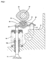
- Fig. 1 shows an upper portion of a cylinder head 10 of an engine.
- the upper portion of the cylinder head 10 is provided with a valve mechanism including a pivot 12, a camshaft 14, an engine valve 16, a valve spring 18, and a rocker arm 20.
- the rocker arm 20 is a roller rocker arm including a roller 22 therein.
- the roller 22 is in contact with a peripheral surface of a cam 24.
- the cam 24 is integrally formed with the camshaft 14.
- One of the ends of the rocker arm 20 includes an abutment 26 to contact an upper end of a stem 16A of the engine valve 16.
- Another end of the rocker arm 20 includes an engaging portion 28 contacting with the pivot 12 of a lash adjuster.
- the rocker arm 20 When the roller 22 is pressed by the cam 24, the rocker arm 20 is rocked about the pivot 12. This causes the upper end of the stem 16A of the engine valve 16 to be depressed by the abutment 26.
- the engine valve 16 thus opens and closes an inlet, or outlet, port of an engine cylinder in a predetermined timing.
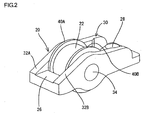
- Fig. 2 is a perspective view of the rocker arm.
- the rocker arm 20 includes a body 30 and the roller 22.
- the roller 22 is mounted in the body 30.
- the body 30 includes two sidewalls 32A, 32B formed by folding a metal plate upwardly into a substantially U-shape.
- the sidewalls 32A, 32B supports a roller shaft 34.
- the roller 22 is rotatably mounted on the roller shaft 34.
- washers 40A, 40B Disposed between the sidewalls 32A, 32B each and the roller 22 are washers 40A, 40B, respectively.
- the washers 40A, 40B in this embodiment correspond to a guiding mechanism.
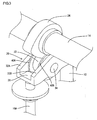
- Fig. 3 is a perspective view showing a state where the rocker arm 20 is installed on the cam 24.
- Fig. 4 is a front view showing the state where the rocker arm 20 is installed on the cam 24.
- the roller shaft 34 forms a rotational axis of the washers 40A, 40B and of the roller 22. Furthermore, the outside diameter D1 of each of the washers 40A, 40B is larger than the outside diameter D2 of the roller 22.
- the rocker arm 20 of this embodiment includes the washers 40A, 40B each between the roller 22 and the respective sidewalls 32A, 32B, and the outside diameter D1 of each of the washers 40A, 40B is larger than the outside diameter D2 of the roller 22.
- the cam 24, which rotates in a constant path, thus guides the rocker arm 20 in an up-and-down direction (in the vertical direction in Fig. 4 ). As this result, when the engine runs the wobbling motion of the rocker arm 20 can be effectively reduced.
- FIG. 5 through 7 A second embodiment which is not covered by the invention invention will be now described with reference to Figs. 5 through 7 .
- This embodiment is different from the first embodiment in that the guiding mechanism is constituted by two flanges 70A, 70B. Constructions similar to the first embodiment are designated by the same numerals, therefore the explanations are omitted.
- Fig. 5 is a perspective view of a rocker arm 50.
- the rocker arm 50 includes a body 60 and a roller 52.
- the roller 52 is mounted in the body 60.
- the body 60 includes two sidewalls 62A, 62B.
- the sidewalls 62A, 62B support a roller shaft 64.
- the roller 52 is rotatably mounted on the roller shaft 64.
- Fig. 6 is a perspective view showing a state where the rocker arm 50 is installed on a cam 70.
- Fig. 7 is a front view showing the state where the rocker arm 50 is installed on the cam 70.
- the cam 70 includes the two flanges 70A, 70B along both edges of the peripheral surface thereof.
- the flanges 70A, 70B in this embodiment which is not covered by the invention correspond to a guiding mechanism.
- Each of the flanges 70A, 70B protrudes from the peripheral surface of the cam 70.
- the rocker arm 50 of this embodiment not covered by the invention includes the two flanges 70A, 70B along the both edges of the peripheral surface of the cam 70, and the roller 52 is held between the two flanges 70A, 70B. Therefore, the flanges 70A, 70B, that are formed with the cam 70 that rotates in a constant path, restricts the roller 52 in movement in the axial direction (the right and left direction in Fig. 7 ). Thus, the flanges 70A, 70B guides the rocker arm 50 having the roller 52 in its vertical movement (the movement in up and down direction in Fig. 7 ). As this result, when the engine runs the wobbling motion of the rocker arm 20 can be effectively reduced.
Landscapes
- Engineering & Computer Science (AREA)
- Mechanical Engineering (AREA)
- General Engineering & Computer Science (AREA)
- Valve-Gear Or Valve Arrangements (AREA)
Claims (1)
- Kipphebel (20), der von einer Nocke (24) angetrieben wird, der umfasst:eine Rolle (22), die aufgebaut ist, um sich zu drehen und eine Last, die von der Nocke (24) gemäß der Drehung der Nocke (24) angewendet wird, aufzunehmen;zwei Seitenwände (32A, 32B), die aufgebaut sind, um die Rolle (22) zu halten; undeinen Führungsmechanismus, der aufgebaut ist, um eine Taumelbewegung der Rolle (22) in Bezug auf die Nocke (24) zu verringern, gekennzeichnet durchdie zwei Seitenwände (32A, 32B), die eine gefaltete Metallplatte sind,den Führungsmechanismus, der zwei Unterlagscheiben (40A, 40B) umfasst, wobei eine erste der zwei Unterlagscheiben (40A, 40B) zwischen einer ersten der zwei Seitenwände (32A, 32B) und der Rolle (22) angeordnet ist, wobei eine zweite der zwei Unterlagscheiben (40A, 40B) zwischen einer zweiten der zwei Seitenwände (32A, 32B) und der Rolle (22) angeordnet ist,Außendurchmesser der zwei Unterlagscheiben (40A, 40B), die größer als ein Außendurchmesser der Rolle (22) sind, unddie Nocke (24), die zwischen den zwei Unterlagscheiben (40A, 40B) angeordnet ist.
Applications Claiming Priority (1)
| Application Number | Priority Date | Filing Date | Title |
|---|---|---|---|
| JP2007175193A JP5069958B2 (ja) | 2007-07-03 | 2007-07-03 | ロッカアーム |
Publications (2)
| Publication Number | Publication Date |
|---|---|
| EP2011973A1 EP2011973A1 (de) | 2009-01-07 |
| EP2011973B1 true EP2011973B1 (de) | 2013-03-20 |
Family
ID=39831608
Family Applications (1)
| Application Number | Title | Priority Date | Filing Date |
|---|---|---|---|
| EP08011527A Not-in-force EP2011973B1 (de) | 2007-07-03 | 2008-06-25 | Kipphebel |
Country Status (3)
| Country | Link |
|---|---|
| US (1) | US8240284B2 (de) |
| EP (1) | EP2011973B1 (de) |
| JP (1) | JP5069958B2 (de) |
Families Citing this family (2)
| Publication number | Priority date | Publication date | Assignee | Title |
|---|---|---|---|---|
| JP5024554B2 (ja) * | 2008-08-26 | 2012-09-12 | 三菱自動車工業株式会社 | 内燃機関の可変動弁装置 |
| JP5519712B2 (ja) | 2012-01-20 | 2014-06-11 | レノボ・シンガポール・プライベート・リミテッド | コンピュータをブートする方法およびコンピュータ |
Family Cites Families (18)
| Publication number | Priority date | Publication date | Assignee | Title |
|---|---|---|---|---|
| JPS60159318A (ja) * | 1984-01-27 | 1985-08-20 | Kawasaki Heavy Ind Ltd | ピボツト式ロツカア−ムの脱落防止装置 |
| JPH0623686Y2 (ja) * | 1986-09-05 | 1994-06-22 | 日本精工株式会社 | カムフオロア装置 |
| JPS63119802U (de) * | 1987-01-29 | 1988-08-03 | ||
| JPH0199906A (ja) | 1987-10-09 | 1989-04-18 | Taisho Pharmaceut Co Ltd | 定形シート片の包装紙への連続挟み込み方法及びその装置 |
| DE4305759A1 (de) * | 1992-09-26 | 1994-03-31 | Volkswagen Ag | Ventiltrieb für ein Hubventil mit einem nockenbetätigten Rollenschlepphebel |
| JP4248111B2 (ja) | 2000-01-20 | 2009-04-02 | 株式会社オティックス | ロッカアームの製造方法 |
| DE10136392A1 (de) * | 2001-07-26 | 2003-02-13 | Volkswagen Ag | Ventiltrieb für ein Hubventil mit einem nockenbetätigten Rollenschlepphebel |
| JP3846250B2 (ja) * | 2001-10-04 | 2006-11-15 | 日本精工株式会社 | ロッカーアーム |
| US6758180B2 (en) | 2001-12-04 | 2004-07-06 | Delphi Technologies, Inc. | Pinless roller finger follower |
| JP4161658B2 (ja) * | 2002-09-18 | 2008-10-08 | 株式会社ジェイテクト | カムフォロアの製造方法 |
| AT6651U1 (de) * | 2003-06-24 | 2004-01-26 | Avl List Gmbh | Variable ventiltriebsvorrichtung für eine brennkraftmaschine |
| WO2005033562A2 (en) * | 2003-10-02 | 2005-04-14 | Jesel, Inc. | Double roller cam follower |
| US7093572B2 (en) * | 2003-12-19 | 2006-08-22 | Delphi Technologies, Inc. | Roller finger follower assembly for valve deactivation |
| JP2005351190A (ja) * | 2004-06-11 | 2005-12-22 | Honda Motor Co Ltd | ローラ付きカムフォロア |
| US20060196459A1 (en) * | 2005-03-01 | 2006-09-07 | Manousos Pattakos | Discrete mode variable valve gear |
| JP4453624B2 (ja) * | 2005-07-21 | 2010-04-21 | 株式会社ジェイテクト | カムフォロア |
| JP4227125B2 (ja) * | 2005-07-28 | 2009-02-18 | 株式会社オティックス | ロッカアームおよび動弁機構 |
| JP2008075555A (ja) * | 2006-09-21 | 2008-04-03 | Otics Corp | ロッカアーム |
-
2007
- 2007-07-03 JP JP2007175193A patent/JP5069958B2/ja not_active Expired - Fee Related
-
2008
- 2008-06-25 EP EP08011527A patent/EP2011973B1/de not_active Not-in-force
- 2008-06-27 US US12/216,030 patent/US8240284B2/en not_active Expired - Fee Related
Also Published As
| Publication number | Publication date |
|---|---|
| JP5069958B2 (ja) | 2012-11-07 |
| EP2011973A1 (de) | 2009-01-07 |
| US8240284B2 (en) | 2012-08-14 |
| US20090007869A1 (en) | 2009-01-08 |
| JP2009013831A (ja) | 2009-01-22 |
Similar Documents
| Publication | Publication Date | Title |
|---|---|---|
| US8047168B2 (en) | Continuously variable valve lift system for engine | |
| EP3196431B1 (de) | Ventiltriebanordnung mit kipphebel | |
| US7363895B2 (en) | Lift-variable valve-operating system for internal combustion engine | |
| JPH04231610A (ja) | ロッカー腕 | |
| EP1666701A1 (de) | Ventiltrieb für verbrennungsmotor | |
| US20130042830A1 (en) | Valve operating apparatus for internal combustion engine | |
| CN107956527A (zh) | 可变气门驱动装置的中间推杆 | |
| US7640900B2 (en) | Variable valve operating device | |
| US8240284B2 (en) | Rocker arm | |
| WO2005068794A1 (ja) | エンジンの動弁装置 | |
| JP4227125B2 (ja) | ロッカアームおよび動弁機構 | |
| CN100436760C (zh) | 内燃机的可变气门传动装置 | |
| JP2006170188A (ja) | 可変カムシステム | |
| CN100427728C (zh) | 发动机的气门传动装置 | |
| WO2005068790A1 (ja) | エンジンの動弁装置 | |
| JP4328966B2 (ja) | 内燃機関の可変動弁装置 | |
| JP4474075B2 (ja) | リフト可変動弁装置 | |
| EP1783332B1 (de) | Oszillierender nocken und dynamischer ventilmechanismus für verbrennungsmotor | |
| JP5197399B2 (ja) | 内燃機関の可変動弁装置 | |
| JP4278607B2 (ja) | 揺動カム装置 | |
| JP2007077982A (ja) | 内燃機関の可変動弁装置 | |
| JP2009150232A (ja) | 内燃機関におけるバルブリフト可変式動弁装置 | |
| JP2006348787A (ja) | 内燃機関の可変動弁装置 | |
| JP2005226541A (ja) | 可変動弁機構 | |
| JP2009133223A (ja) | 内燃機関のバルブリフト可変式動弁装置 |
Legal Events
| Date | Code | Title | Description |
|---|---|---|---|
| PUAI | Public reference made under article 153(3) epc to a published international application that has entered the european phase |
Free format text: ORIGINAL CODE: 0009012 |
|
| AK | Designated contracting states |
Kind code of ref document: A1 Designated state(s): AT BE BG CH CY CZ DE DK EE ES FI FR GB GR HR HU IE IS IT LI LT LU LV MC MT NL NO PL PT RO SE SI SK TR |
|
| AX | Request for extension of the european patent |
Extension state: AL BA MK RS |
|
| 17P | Request for examination filed |
Effective date: 20090702 |
|
| AKX | Designation fees paid |
Designated state(s): AT BE BG CH CY CZ DE DK EE ES FI FR GB GR HR HU IE IS IT LI LT LU LV MC MT NL NO PL PT RO SE SI SK TR |
|
| 17Q | First examination report despatched |
Effective date: 20090814 |
|
| GRAP | Despatch of communication of intention to grant a patent |
Free format text: ORIGINAL CODE: EPIDOSNIGR1 |
|
| GRAJ | Information related to disapproval of communication of intention to grant by the applicant or resumption of examination proceedings by the epo deleted |
Free format text: ORIGINAL CODE: EPIDOSDIGR1 |
|
| GRAP | Despatch of communication of intention to grant a patent |
Free format text: ORIGINAL CODE: EPIDOSNIGR1 |
|
| GRAS | Grant fee paid |
Free format text: ORIGINAL CODE: EPIDOSNIGR3 |
|
| GRAA | (expected) grant |
Free format text: ORIGINAL CODE: 0009210 |
|
| RIN1 | Information on inventor provided before grant (corrected) |
Inventor name: SAKURAI, MASAHIDE Inventor name: HIRAMATSU, NAOKI |
|
| AK | Designated contracting states |
Kind code of ref document: B1 Designated state(s): AT BE BG CH CY CZ DE DK EE ES FI FR GB GR HR HU IE IS IT LI LT LU LV MC MT NL NO PL PT RO SE SI SK TR |
|
| REG | Reference to a national code |
Ref country code: GB Ref legal event code: FG4D |
|
| REG | Reference to a national code |
Ref country code: CH Ref legal event code: EP |
|
| REG | Reference to a national code |
Ref country code: IE Ref legal event code: FG4D |
|
| REG | Reference to a national code |
Ref country code: AT Ref legal event code: REF Ref document number: 602217 Country of ref document: AT Kind code of ref document: T Effective date: 20130415 |
|
| REG | Reference to a national code |
Ref country code: DE Ref legal event code: R096 Ref document number: 602008022971 Country of ref document: DE Effective date: 20130508 |
|
| PG25 | Lapsed in a contracting state [announced via postgrant information from national office to epo] |
Ref country code: SE Free format text: LAPSE BECAUSE OF FAILURE TO SUBMIT A TRANSLATION OF THE DESCRIPTION OR TO PAY THE FEE WITHIN THE PRESCRIBED TIME-LIMIT Effective date: 20130320 Ref country code: BG Free format text: LAPSE BECAUSE OF FAILURE TO SUBMIT A TRANSLATION OF THE DESCRIPTION OR TO PAY THE FEE WITHIN THE PRESCRIBED TIME-LIMIT Effective date: 20130620 Ref country code: LT Free format text: LAPSE BECAUSE OF FAILURE TO SUBMIT A TRANSLATION OF THE DESCRIPTION OR TO PAY THE FEE WITHIN THE PRESCRIBED TIME-LIMIT Effective date: 20130320 Ref country code: ES Free format text: LAPSE BECAUSE OF FAILURE TO SUBMIT A TRANSLATION OF THE DESCRIPTION OR TO PAY THE FEE WITHIN THE PRESCRIBED TIME-LIMIT Effective date: 20130701 Ref country code: NO Free format text: LAPSE BECAUSE OF FAILURE TO SUBMIT A TRANSLATION OF THE DESCRIPTION OR TO PAY THE FEE WITHIN THE PRESCRIBED TIME-LIMIT Effective date: 20130620 |
|
| REG | Reference to a national code |
Ref country code: AT Ref legal event code: MK05 Ref document number: 602217 Country of ref document: AT Kind code of ref document: T Effective date: 20130320 |
|
| REG | Reference to a national code |
Ref country code: LT Ref legal event code: MG4D |
|
| PG25 | Lapsed in a contracting state [announced via postgrant information from national office to epo] |
Ref country code: LV Free format text: LAPSE BECAUSE OF FAILURE TO SUBMIT A TRANSLATION OF THE DESCRIPTION OR TO PAY THE FEE WITHIN THE PRESCRIBED TIME-LIMIT Effective date: 20130320 Ref country code: FI Free format text: LAPSE BECAUSE OF FAILURE TO SUBMIT A TRANSLATION OF THE DESCRIPTION OR TO PAY THE FEE WITHIN THE PRESCRIBED TIME-LIMIT Effective date: 20130320 Ref country code: GR Free format text: LAPSE BECAUSE OF FAILURE TO SUBMIT A TRANSLATION OF THE DESCRIPTION OR TO PAY THE FEE WITHIN THE PRESCRIBED TIME-LIMIT Effective date: 20130621 Ref country code: SI Free format text: LAPSE BECAUSE OF FAILURE TO SUBMIT A TRANSLATION OF THE DESCRIPTION OR TO PAY THE FEE WITHIN THE PRESCRIBED TIME-LIMIT Effective date: 20130320 |
|
| REG | Reference to a national code |
Ref country code: NL Ref legal event code: VDEP Effective date: 20130320 |
|
| PG25 | Lapsed in a contracting state [announced via postgrant information from national office to epo] |
Ref country code: HR Free format text: LAPSE BECAUSE OF FAILURE TO SUBMIT A TRANSLATION OF THE DESCRIPTION OR TO PAY THE FEE WITHIN THE PRESCRIBED TIME-LIMIT Effective date: 20130320 Ref country code: BE Free format text: LAPSE BECAUSE OF FAILURE TO SUBMIT A TRANSLATION OF THE DESCRIPTION OR TO PAY THE FEE WITHIN THE PRESCRIBED TIME-LIMIT Effective date: 20130320 |
|
| PG25 | Lapsed in a contracting state [announced via postgrant information from national office to epo] |
Ref country code: IS Free format text: LAPSE BECAUSE OF FAILURE TO SUBMIT A TRANSLATION OF THE DESCRIPTION OR TO PAY THE FEE WITHIN THE PRESCRIBED TIME-LIMIT Effective date: 20130720 Ref country code: SK Free format text: LAPSE BECAUSE OF FAILURE TO SUBMIT A TRANSLATION OF THE DESCRIPTION OR TO PAY THE FEE WITHIN THE PRESCRIBED TIME-LIMIT Effective date: 20130320 Ref country code: AT Free format text: LAPSE BECAUSE OF FAILURE TO SUBMIT A TRANSLATION OF THE DESCRIPTION OR TO PAY THE FEE WITHIN THE PRESCRIBED TIME-LIMIT Effective date: 20130320 Ref country code: EE Free format text: LAPSE BECAUSE OF FAILURE TO SUBMIT A TRANSLATION OF THE DESCRIPTION OR TO PAY THE FEE WITHIN THE PRESCRIBED TIME-LIMIT Effective date: 20130320 Ref country code: NL Free format text: LAPSE BECAUSE OF FAILURE TO SUBMIT A TRANSLATION OF THE DESCRIPTION OR TO PAY THE FEE WITHIN THE PRESCRIBED TIME-LIMIT Effective date: 20130320 Ref country code: RO Free format text: LAPSE BECAUSE OF FAILURE TO SUBMIT A TRANSLATION OF THE DESCRIPTION OR TO PAY THE FEE WITHIN THE PRESCRIBED TIME-LIMIT Effective date: 20130320 Ref country code: PT Free format text: LAPSE BECAUSE OF FAILURE TO SUBMIT A TRANSLATION OF THE DESCRIPTION OR TO PAY THE FEE WITHIN THE PRESCRIBED TIME-LIMIT Effective date: 20130722 Ref country code: CZ Free format text: LAPSE BECAUSE OF FAILURE TO SUBMIT A TRANSLATION OF THE DESCRIPTION OR TO PAY THE FEE WITHIN THE PRESCRIBED TIME-LIMIT Effective date: 20130320 |
|
| PG25 | Lapsed in a contracting state [announced via postgrant information from national office to epo] |
Ref country code: CY Free format text: LAPSE BECAUSE OF FAILURE TO SUBMIT A TRANSLATION OF THE DESCRIPTION OR TO PAY THE FEE WITHIN THE PRESCRIBED TIME-LIMIT Effective date: 20130320 Ref country code: PL Free format text: LAPSE BECAUSE OF FAILURE TO SUBMIT A TRANSLATION OF THE DESCRIPTION OR TO PAY THE FEE WITHIN THE PRESCRIBED TIME-LIMIT Effective date: 20130320 |
|
| PLBE | No opposition filed within time limit |
Free format text: ORIGINAL CODE: 0009261 |
|
| STAA | Information on the status of an ep patent application or granted ep patent |
Free format text: STATUS: NO OPPOSITION FILED WITHIN TIME LIMIT |
|
| PG25 | Lapsed in a contracting state [announced via postgrant information from national office to epo] |
Ref country code: MC Free format text: LAPSE BECAUSE OF FAILURE TO SUBMIT A TRANSLATION OF THE DESCRIPTION OR TO PAY THE FEE WITHIN THE PRESCRIBED TIME-LIMIT Effective date: 20130320 Ref country code: DK Free format text: LAPSE BECAUSE OF FAILURE TO SUBMIT A TRANSLATION OF THE DESCRIPTION OR TO PAY THE FEE WITHIN THE PRESCRIBED TIME-LIMIT Effective date: 20130320 |
|
| REG | Reference to a national code |
Ref country code: CH Ref legal event code: PL |
|
| 26N | No opposition filed |
Effective date: 20140102 |
|
| GBPC | Gb: european patent ceased through non-payment of renewal fee |
Effective date: 20130625 |
|
| PG25 | Lapsed in a contracting state [announced via postgrant information from national office to epo] |
Ref country code: IT Free format text: LAPSE BECAUSE OF FAILURE TO SUBMIT A TRANSLATION OF THE DESCRIPTION OR TO PAY THE FEE WITHIN THE PRESCRIBED TIME-LIMIT Effective date: 20130320 |
|
| REG | Reference to a national code |
Ref country code: IE Ref legal event code: MM4A |
|
| REG | Reference to a national code |
Ref country code: DE Ref legal event code: R119 Ref document number: 602008022971 Country of ref document: DE Effective date: 20140101 |
|
| REG | Reference to a national code |
Ref country code: FR Ref legal event code: ST Effective date: 20140228 |
|
| PG25 | Lapsed in a contracting state [announced via postgrant information from national office to epo] |
Ref country code: GB Free format text: LAPSE BECAUSE OF NON-PAYMENT OF DUE FEES Effective date: 20130625 Ref country code: CH Free format text: LAPSE BECAUSE OF NON-PAYMENT OF DUE FEES Effective date: 20130630 Ref country code: IE Free format text: LAPSE BECAUSE OF NON-PAYMENT OF DUE FEES Effective date: 20130625 Ref country code: DE Free format text: LAPSE BECAUSE OF NON-PAYMENT OF DUE FEES Effective date: 20140101 Ref country code: LI Free format text: LAPSE BECAUSE OF NON-PAYMENT OF DUE FEES Effective date: 20130630 |
|
| PG25 | Lapsed in a contracting state [announced via postgrant information from national office to epo] |
Ref country code: FR Free format text: LAPSE BECAUSE OF NON-PAYMENT OF DUE FEES Effective date: 20130701 |
|
| PG25 | Lapsed in a contracting state [announced via postgrant information from national office to epo] |
Ref country code: MT Free format text: LAPSE BECAUSE OF FAILURE TO SUBMIT A TRANSLATION OF THE DESCRIPTION OR TO PAY THE FEE WITHIN THE PRESCRIBED TIME-LIMIT Effective date: 20130320 |
|
| PG25 | Lapsed in a contracting state [announced via postgrant information from national office to epo] |
Ref country code: TR Free format text: LAPSE BECAUSE OF FAILURE TO SUBMIT A TRANSLATION OF THE DESCRIPTION OR TO PAY THE FEE WITHIN THE PRESCRIBED TIME-LIMIT Effective date: 20130320 |
|
| PG25 | Lapsed in a contracting state [announced via postgrant information from national office to epo] |
Ref country code: LU Free format text: LAPSE BECAUSE OF NON-PAYMENT OF DUE FEES Effective date: 20130625 Ref country code: HU Free format text: LAPSE BECAUSE OF FAILURE TO SUBMIT A TRANSLATION OF THE DESCRIPTION OR TO PAY THE FEE WITHIN THE PRESCRIBED TIME-LIMIT; INVALID AB INITIO Effective date: 20080625 |