EP2011661A1 - Optical recording medium, visible information recording method and use of dye compound - Google Patents
Optical recording medium, visible information recording method and use of dye compound Download PDFInfo
- Publication number
- EP2011661A1 EP2011661A1 EP07740987A EP07740987A EP2011661A1 EP 2011661 A1 EP2011661 A1 EP 2011661A1 EP 07740987 A EP07740987 A EP 07740987A EP 07740987 A EP07740987 A EP 07740987A EP 2011661 A1 EP2011661 A1 EP 2011661A1
- Authority
- EP
- European Patent Office
- Prior art keywords
- group
- recording medium
- substituted
- optical recording
- information recording
- Prior art date
- Legal status (The legal status is an assumption and is not a legal conclusion. Google has not performed a legal analysis and makes no representation as to the accuracy of the status listed.)
- Withdrawn
Links
- 230000003287 optical effect Effects 0.000 title claims abstract description 119
- 150000001875 compounds Chemical class 0.000 title claims abstract description 70
- 238000000034 method Methods 0.000 title claims description 35
- 239000000758 substrate Substances 0.000 claims abstract description 97
- 125000001931 aliphatic group Chemical group 0.000 claims abstract description 56
- 125000003118 aryl group Chemical group 0.000 claims abstract description 39
- 125000000623 heterocyclic group Chemical group 0.000 claims abstract description 39
- 125000001424 substituent group Chemical group 0.000 claims abstract description 36
- 125000004435 hydrogen atom Chemical group [H]* 0.000 claims abstract description 35
- 125000003341 7 membered heterocyclic group Chemical group 0.000 claims abstract description 17
- 125000004432 carbon atom Chemical group C* 0.000 claims description 37
- 239000000463 material Substances 0.000 claims description 29
- 125000000217 alkyl group Chemical group 0.000 claims description 25
- 229910052799 carbon Inorganic materials 0.000 claims description 6
- 229910052757 nitrogen Inorganic materials 0.000 claims description 6
- 125000004433 nitrogen atom Chemical group N* 0.000 claims description 6
- 229910052755 nonmetal Inorganic materials 0.000 claims description 2
- 125000002755 pyrazolinyl group Chemical group 0.000 claims description 2
- KAESVJOAVNADME-UHFFFAOYSA-N Pyrrole Chemical group C=1C=CNC=1 KAESVJOAVNADME-UHFFFAOYSA-N 0.000 claims 3
- 239000010410 layer Substances 0.000 description 260
- 239000000975 dye Substances 0.000 description 99
- -1 sulfonyloxy group Chemical group 0.000 description 33
- 238000000576 coating method Methods 0.000 description 27
- 239000011248 coating agent Substances 0.000 description 23
- 239000012790 adhesive layer Substances 0.000 description 22
- 239000011347 resin Substances 0.000 description 19
- 229920005989 resin Polymers 0.000 description 19
- 239000011241 protective layer Substances 0.000 description 17
- 239000002904 solvent Substances 0.000 description 16
- 238000001454 recorded image Methods 0.000 description 13
- 230000008859 change Effects 0.000 description 11
- 239000000126 substance Substances 0.000 description 11
- 238000011156 evaluation Methods 0.000 description 10
- KLSJWNVTNUYHDU-UHFFFAOYSA-N Amitrole Chemical group NC1=NC=NN1 KLSJWNVTNUYHDU-UHFFFAOYSA-N 0.000 description 9
- 238000005562 fading Methods 0.000 description 9
- 239000007788 liquid Substances 0.000 description 9
- 239000011230 binding agent Substances 0.000 description 8
- ANRHNWWPFJCPAZ-UHFFFAOYSA-M thionine Chemical compound [Cl-].C1=CC(N)=CC2=[S+]C3=CC(N)=CC=C3N=C21 ANRHNWWPFJCPAZ-UHFFFAOYSA-M 0.000 description 8
- 125000003277 amino group Chemical group 0.000 description 7
- 239000000987 azo dye Substances 0.000 description 7
- 239000003795 chemical substances by application Substances 0.000 description 7
- 230000001678 irradiating effect Effects 0.000 description 7
- 125000001820 oxy group Chemical group [*:1]O[*:2] 0.000 description 7
- 238000004528 spin coating Methods 0.000 description 7
- MYMOFIZGZYHOMD-UHFFFAOYSA-N Dioxygen Chemical compound O=O MYMOFIZGZYHOMD-UHFFFAOYSA-N 0.000 description 6
- 230000001965 increasing effect Effects 0.000 description 6
- PXHVJJICTQNCMI-UHFFFAOYSA-N nickel Substances [Ni] PXHVJJICTQNCMI-UHFFFAOYSA-N 0.000 description 6
- 125000000565 sulfonamide group Chemical group 0.000 description 6
- 239000000654 additive Substances 0.000 description 5
- 150000001721 carbon Chemical group 0.000 description 5
- 230000000052 comparative effect Effects 0.000 description 5
- 239000000470 constituent Substances 0.000 description 5
- 229920001577 copolymer Polymers 0.000 description 5
- 238000010030 laminating Methods 0.000 description 5
- 229910052759 nickel Inorganic materials 0.000 description 5
- 125000005740 oxycarbonyl group Chemical group [*:1]OC([*:2])=O 0.000 description 5
- 239000001007 phthalocyanine dye Substances 0.000 description 5
- 239000004417 polycarbonate Substances 0.000 description 5
- 229920000515 polycarbonate Polymers 0.000 description 5
- 239000000243 solution Substances 0.000 description 5
- 125000004442 acylamino group Chemical group 0.000 description 4
- 125000004421 aryl sulphonamide group Chemical group 0.000 description 4
- 125000004093 cyano group Chemical group *C#N 0.000 description 4
- 125000002887 hydroxy group Chemical group [H]O* 0.000 description 4
- 239000000314 lubricant Substances 0.000 description 4
- 239000004014 plasticizer Substances 0.000 description 4
- 239000004800 polyvinyl chloride Substances 0.000 description 4
- 230000008569 process Effects 0.000 description 4
- 238000004544 sputter deposition Methods 0.000 description 4
- 125000000547 substituted alkyl group Chemical group 0.000 description 4
- 125000000472 sulfonyl group Chemical group *S(*)(=O)=O 0.000 description 4
- 239000006097 ultraviolet radiation absorber Substances 0.000 description 4
- 230000000007 visual effect Effects 0.000 description 4
- 125000001376 1,2,4-triazolyl group Chemical group N1N=C(N=C1)* 0.000 description 3
- NBUKAOOFKZFCGD-UHFFFAOYSA-N 2,2,3,3-tetrafluoropropan-1-ol Chemical compound OCC(F)(F)C(F)F NBUKAOOFKZFCGD-UHFFFAOYSA-N 0.000 description 3
- ZWEHNKRNPOVVGH-UHFFFAOYSA-N 2-Butanone Chemical compound CCC(C)=O ZWEHNKRNPOVVGH-UHFFFAOYSA-N 0.000 description 3
- MCGBIXXDQFWVDW-UHFFFAOYSA-N 4,5-dihydro-1h-pyrazole Chemical group C1CC=NN1 MCGBIXXDQFWVDW-UHFFFAOYSA-N 0.000 description 3
- YMWUJEATGCHHMB-UHFFFAOYSA-N Dichloromethane Chemical compound ClCCl YMWUJEATGCHHMB-UHFFFAOYSA-N 0.000 description 3
- RTZKZFJDLAIYFH-UHFFFAOYSA-N Diethyl ether Chemical compound CCOCC RTZKZFJDLAIYFH-UHFFFAOYSA-N 0.000 description 3
- LFQSCWFLJHTTHZ-UHFFFAOYSA-N Ethanol Chemical compound CCO LFQSCWFLJHTTHZ-UHFFFAOYSA-N 0.000 description 3
- WSFSSNUMVMOOMR-UHFFFAOYSA-N Formaldehyde Chemical compound O=C WSFSSNUMVMOOMR-UHFFFAOYSA-N 0.000 description 3
- 125000002252 acyl group Chemical group 0.000 description 3
- 125000004423 acyloxy group Chemical group 0.000 description 3
- 239000002313 adhesive film Substances 0.000 description 3
- 229910052782 aluminium Inorganic materials 0.000 description 3
- 125000004397 aminosulfonyl group Chemical group NS(=O)(=O)* 0.000 description 3
- 239000003963 antioxidant agent Substances 0.000 description 3
- 125000005162 aryl oxy carbonyl amino group Chemical group 0.000 description 3
- 125000005279 aryl sulfonyloxy group Chemical group 0.000 description 3
- 125000003917 carbamoyl group Chemical group [H]N([H])C(*)=O 0.000 description 3
- 125000003178 carboxy group Chemical group [H]OC(*)=O 0.000 description 3
- 229910052802 copper Inorganic materials 0.000 description 3
- 230000000694 effects Effects 0.000 description 3
- 230000002708 enhancing effect Effects 0.000 description 3
- 239000003822 epoxy resin Substances 0.000 description 3
- 239000011521 glass Substances 0.000 description 3
- 150000002430 hydrocarbons Chemical group 0.000 description 3
- 238000004519 manufacturing process Methods 0.000 description 3
- 230000007246 mechanism Effects 0.000 description 3
- 239000002184 metal Substances 0.000 description 3
- 229910052751 metal Inorganic materials 0.000 description 3
- 229920003229 poly(methyl methacrylate) Polymers 0.000 description 3
- 229920000647 polyepoxide Polymers 0.000 description 3
- 239000004926 polymethyl methacrylate Substances 0.000 description 3
- 229920000915 polyvinyl chloride Polymers 0.000 description 3
- JEXVQSWXXUJEMA-UHFFFAOYSA-N pyrazol-3-one Chemical compound O=C1C=CN=N1 JEXVQSWXXUJEMA-UHFFFAOYSA-N 0.000 description 3
- DNXIASIHZYFFRO-UHFFFAOYSA-N pyrazoline Chemical group C1CN=NC1 DNXIASIHZYFFRO-UHFFFAOYSA-N 0.000 description 3
- 239000004065 semiconductor Substances 0.000 description 3
- 229910052709 silver Inorganic materials 0.000 description 3
- 239000002356 single layer Substances 0.000 description 3
- 125000000020 sulfo group Chemical group O=S(=O)([*])O[H] 0.000 description 3
- XJDDLMJULQGRLU-UHFFFAOYSA-N 1,3-dioxane-4,6-dione Chemical compound O=C1CC(=O)OCO1 XJDDLMJULQGRLU-UHFFFAOYSA-N 0.000 description 2
- RVBUGGBMJDPOST-UHFFFAOYSA-N 2-thiobarbituric acid Chemical compound O=C1CC(=O)NC(=S)N1 RVBUGGBMJDPOST-UHFFFAOYSA-N 0.000 description 2
- NIXOWILDQLNWCW-UHFFFAOYSA-M Acrylate Chemical compound [O-]C(=O)C=C NIXOWILDQLNWCW-UHFFFAOYSA-M 0.000 description 2
- 239000004925 Acrylic resin Substances 0.000 description 2
- 229920000178 Acrylic resin Polymers 0.000 description 2
- 229920002284 Cellulose triacetate Polymers 0.000 description 2
- HEDRZPFGACZZDS-UHFFFAOYSA-N Chloroform Chemical compound ClC(Cl)Cl HEDRZPFGACZZDS-UHFFFAOYSA-N 0.000 description 2
- KFZMGEQAYNKOFK-UHFFFAOYSA-N Isopropanol Chemical compound CC(C)O KFZMGEQAYNKOFK-UHFFFAOYSA-N 0.000 description 2
- 239000004698 Polyethylene Substances 0.000 description 2
- 239000004743 Polypropylene Substances 0.000 description 2
- 239000004372 Polyvinyl alcohol Substances 0.000 description 2
- VYPSYNLAJGMNEJ-UHFFFAOYSA-N Silicium dioxide Chemical compound O=[Si]=O VYPSYNLAJGMNEJ-UHFFFAOYSA-N 0.000 description 2
- PPBRXRYQALVLMV-UHFFFAOYSA-N Styrene Chemical compound C=CC1=CC=CC=C1 PPBRXRYQALVLMV-UHFFFAOYSA-N 0.000 description 2
- WYURNTSHIVDZCO-UHFFFAOYSA-N Tetrahydrofuran Chemical compound C1CCOC1 WYURNTSHIVDZCO-UHFFFAOYSA-N 0.000 description 2
- NNLVGZFZQQXQNW-ADJNRHBOSA-N [(2r,3r,4s,5r,6s)-4,5-diacetyloxy-3-[(2s,3r,4s,5r,6r)-3,4,5-triacetyloxy-6-(acetyloxymethyl)oxan-2-yl]oxy-6-[(2r,3r,4s,5r,6s)-4,5,6-triacetyloxy-2-(acetyloxymethyl)oxan-3-yl]oxyoxan-2-yl]methyl acetate Chemical compound O([C@@H]1O[C@@H]([C@H]([C@H](OC(C)=O)[C@H]1OC(C)=O)O[C@H]1[C@@H]([C@@H](OC(C)=O)[C@H](OC(C)=O)[C@@H](COC(C)=O)O1)OC(C)=O)COC(=O)C)[C@@H]1[C@@H](COC(C)=O)O[C@@H](OC(C)=O)[C@H](OC(C)=O)[C@H]1OC(C)=O NNLVGZFZQQXQNW-ADJNRHBOSA-N 0.000 description 2
- 230000002378 acidificating effect Effects 0.000 description 2
- 230000032683 aging Effects 0.000 description 2
- 125000003342 alkenyl group Chemical group 0.000 description 2
- 229910045601 alloy Inorganic materials 0.000 description 2
- 239000000956 alloy Substances 0.000 description 2
- 230000003078 antioxidant effect Effects 0.000 description 2
- 125000001769 aryl amino group Chemical group 0.000 description 2
- 125000005161 aryl oxy carbonyl group Chemical group 0.000 description 2
- 125000005135 aryl sulfinyl group Chemical group 0.000 description 2
- 125000004391 aryl sulfonyl group Chemical group 0.000 description 2
- 125000004104 aryloxy group Chemical group 0.000 description 2
- HNYOPLTXPVRDBG-UHFFFAOYSA-N barbituric acid Chemical compound O=C1CC(=O)NC(=O)N1 HNYOPLTXPVRDBG-UHFFFAOYSA-N 0.000 description 2
- 125000001951 carbamoylamino group Chemical group C(N)(=O)N* 0.000 description 2
- 229910052804 chromium Inorganic materials 0.000 description 2
- JHIVVAPYMSGYDF-UHFFFAOYSA-N cyclohexanone Chemical compound O=C1CCCCC1 JHIVVAPYMSGYDF-UHFFFAOYSA-N 0.000 description 2
- SWXVUIWOUIDPGS-UHFFFAOYSA-N diacetone alcohol Chemical compound CC(=O)CC(C)(C)O SWXVUIWOUIDPGS-UHFFFAOYSA-N 0.000 description 2
- 229920001971 elastomer Polymers 0.000 description 2
- LZCLXQDLBQLTDK-UHFFFAOYSA-N ethyl 2-hydroxypropanoate Chemical compound CCOC(=O)C(C)O LZCLXQDLBQLTDK-UHFFFAOYSA-N 0.000 description 2
- 230000006870 function Effects 0.000 description 2
- 229910052737 gold Inorganic materials 0.000 description 2
- 125000005843 halogen group Chemical group 0.000 description 2
- 229930195733 hydrocarbon Natural products 0.000 description 2
- 229910052738 indium Inorganic materials 0.000 description 2
- 238000001746 injection moulding Methods 0.000 description 2
- 125000001449 isopropyl group Chemical group [H]C([H])([H])C([H])(*)C([H])([H])[H] 0.000 description 2
- 239000000178 monomer Substances 0.000 description 2
- 229920002120 photoresistant polymer Polymers 0.000 description 2
- 229910052697 platinum Inorganic materials 0.000 description 2
- 229920000728 polyester Polymers 0.000 description 2
- 229920000573 polyethylene Polymers 0.000 description 2
- 229920000098 polyolefin Polymers 0.000 description 2
- 229920002451 polyvinyl alcohol Polymers 0.000 description 2
- BDERNNFJNOPAEC-UHFFFAOYSA-N propan-1-ol Chemical compound CCCO BDERNNFJNOPAEC-UHFFFAOYSA-N 0.000 description 2
- 230000001681 protective effect Effects 0.000 description 2
- MCSKRVKAXABJLX-UHFFFAOYSA-N pyrazolo[3,4-d]triazole Chemical group N1=NN=C2N=NC=C21 MCSKRVKAXABJLX-UHFFFAOYSA-N 0.000 description 2
- 125000003226 pyrazolyl group Chemical group 0.000 description 2
- 238000007650 screen-printing Methods 0.000 description 2
- 239000007787 solid Substances 0.000 description 2
- 229910001220 stainless steel Inorganic materials 0.000 description 2
- 239000010935 stainless steel Substances 0.000 description 2
- 125000000475 sulfinyl group Chemical group [*:2]S([*:1])=O 0.000 description 2
- 229920001187 thermosetting polymer Polymers 0.000 description 2
- 150000003918 triazines Chemical class 0.000 description 2
- BUNYBPVXEKRSGY-ONEGZZNKSA-N (1e)-buta-1,3-dien-1-amine Chemical class N\C=C\C=C BUNYBPVXEKRSGY-ONEGZZNKSA-N 0.000 description 1
- CHGIHNHFMQGPDX-UHFFFAOYSA-N 1,1-dioxothiophen-3-one Chemical compound O=C1CS(=O)(=O)C=C1 CHGIHNHFMQGPDX-UHFFFAOYSA-N 0.000 description 1
- FYADHXFMURLYQI-UHFFFAOYSA-N 1,2,4-triazine Chemical group C1=CN=NC=N1 FYADHXFMURLYQI-UHFFFAOYSA-N 0.000 description 1
- WSLDOOZREJYCGB-UHFFFAOYSA-N 1,2-Dichloroethane Chemical compound ClCCCl WSLDOOZREJYCGB-UHFFFAOYSA-N 0.000 description 1
- ZBOWKDHBOFMERX-UHFFFAOYSA-N 1,3-diazepane Chemical compound C1CCNCNC1 ZBOWKDHBOFMERX-UHFFFAOYSA-N 0.000 description 1
- DKYBVKMIZODYKL-UHFFFAOYSA-N 1,3-diazinane Chemical group C1CNCNC1 DKYBVKMIZODYKL-UHFFFAOYSA-N 0.000 description 1
- UHKAJLSKXBADFT-UHFFFAOYSA-N 1,3-indandione Chemical compound C1=CC=C2C(=O)CC(=O)C2=C1 UHKAJLSKXBADFT-UHFFFAOYSA-N 0.000 description 1
- RYHBNJHYFVUHQT-UHFFFAOYSA-N 1,4-Dioxane Chemical compound C1COCCO1 RYHBNJHYFVUHQT-UHFFFAOYSA-N 0.000 description 1
- QLCJOAMJPCOIDI-UHFFFAOYSA-N 1-(butoxymethoxy)butane Chemical compound CCCCOCOCCCC QLCJOAMJPCOIDI-UHFFFAOYSA-N 0.000 description 1
- DURPTKYDGMDSBL-UHFFFAOYSA-N 1-butoxybutane Chemical compound CCCCOCCCC DURPTKYDGMDSBL-UHFFFAOYSA-N 0.000 description 1
- ARXJGSRGQADJSQ-UHFFFAOYSA-N 1-methoxypropan-2-ol Chemical compound COCC(C)O ARXJGSRGQADJSQ-UHFFFAOYSA-N 0.000 description 1
- SMZOUWXMTYCWNB-UHFFFAOYSA-N 2-(2-methoxy-5-methylphenyl)ethanamine Chemical compound COC1=CC=C(C)C=C1CCN SMZOUWXMTYCWNB-UHFFFAOYSA-N 0.000 description 1
- XNWFRZJHXBZDAG-UHFFFAOYSA-N 2-METHOXYETHANOL Chemical compound COCCO XNWFRZJHXBZDAG-UHFFFAOYSA-N 0.000 description 1
- NIXOWILDQLNWCW-UHFFFAOYSA-N 2-Propenoic acid Natural products OC(=O)C=C NIXOWILDQLNWCW-UHFFFAOYSA-N 0.000 description 1
- KVUPQEKUVSNRCD-UHFFFAOYSA-N 2-amino-1,3-oxazol-4-one Chemical compound NC1=NC(=O)CO1 KVUPQEKUVSNRCD-UHFFFAOYSA-N 0.000 description 1
- ZNQVEEAIQZEUHB-UHFFFAOYSA-N 2-ethoxyethanol Chemical compound CCOCCO ZNQVEEAIQZEUHB-UHFFFAOYSA-N 0.000 description 1
- SVONRAPFKPVNKG-UHFFFAOYSA-N 2-ethoxyethyl acetate Chemical compound CCOCCOC(C)=O SVONRAPFKPVNKG-UHFFFAOYSA-N 0.000 description 1
- UGWULZWUXSCWPX-UHFFFAOYSA-N 2-sulfanylideneimidazolidin-4-one Chemical compound O=C1CNC(=S)N1 UGWULZWUXSCWPX-UHFFFAOYSA-N 0.000 description 1
- CAAMSDWKXXPUJR-UHFFFAOYSA-N 3,5-dihydro-4H-imidazol-4-one Chemical compound O=C1CNC=N1 CAAMSDWKXXPUJR-UHFFFAOYSA-N 0.000 description 1
- PVLKSJIUOKAUMV-UHFFFAOYSA-N 3-oxohexanal Chemical compound CCCC(=O)CC=O PVLKSJIUOKAUMV-UHFFFAOYSA-N 0.000 description 1
- ZNNXJRURXWWGLN-UHFFFAOYSA-N 3-oxopentanal Chemical compound CCC(=O)CC=O ZNNXJRURXWWGLN-UHFFFAOYSA-N 0.000 description 1
- DZOKENUNRMDZCS-UHFFFAOYSA-N 3h-isoquinolin-4-one Chemical compound C1=CC=C2C(=O)CN=CC2=C1 DZOKENUNRMDZCS-UHFFFAOYSA-N 0.000 description 1
- 125000004172 4-methoxyphenyl group Chemical group [H]C1=C([H])C(OC([H])([H])[H])=C([H])C([H])=C1* 0.000 description 1
- XTSVDOIDJDJMDS-UHFFFAOYSA-N 4-sulfanylidene-1,3-thiazolidin-2-one Chemical compound O=C1NC(=S)CS1 XTSVDOIDJDJMDS-UHFFFAOYSA-N 0.000 description 1
- DNPNXLYNSXZPGM-UHFFFAOYSA-N 4-sulfanylideneimidazolidin-2-one Chemical compound O=C1NCC(=S)N1 DNPNXLYNSXZPGM-UHFFFAOYSA-N 0.000 description 1
- DANDTMGGYNCQLG-UHFFFAOYSA-N 4h-1,3-oxazol-5-one Chemical compound O=C1CN=CO1 DANDTMGGYNCQLG-UHFFFAOYSA-N 0.000 description 1
- 125000002373 5 membered heterocyclic group Chemical group 0.000 description 1
- RSWGJHLUYNHPMX-UHFFFAOYSA-N Abietic-Saeure Natural products C12CCC(C(C)C)=CC2=CCC2C1(C)CCCC2(C)C(O)=O RSWGJHLUYNHPMX-UHFFFAOYSA-N 0.000 description 1
- 229920002126 Acrylic acid copolymer Polymers 0.000 description 1
- 229910001316 Ag alloy Inorganic materials 0.000 description 1
- DKPFZGUDAPQIHT-UHFFFAOYSA-N Butyl acetate Natural products CCCCOC(C)=O DKPFZGUDAPQIHT-UHFFFAOYSA-N 0.000 description 1
- OKTJSMMVPCPJKN-UHFFFAOYSA-N Carbon Chemical group [C] OKTJSMMVPCPJKN-UHFFFAOYSA-N 0.000 description 1
- 239000004215 Carbon black (E152) Substances 0.000 description 1
- 239000004709 Chlorinated polyethylene Substances 0.000 description 1
- 229920002307 Dextran Polymers 0.000 description 1
- VGGSQFUCUMXWEO-UHFFFAOYSA-N Ethene Chemical compound C=C VGGSQFUCUMXWEO-UHFFFAOYSA-N 0.000 description 1
- 239000005977 Ethylene Substances 0.000 description 1
- 108010010803 Gelatin Proteins 0.000 description 1
- NTIZESTWPVYFNL-UHFFFAOYSA-N Methyl isobutyl ketone Chemical compound CC(C)CC(C)=O NTIZESTWPVYFNL-UHFFFAOYSA-N 0.000 description 1
- UIHCLUNTQKBZGK-UHFFFAOYSA-N Methyl isobutyl ketone Natural products CCC(C)C(C)=O UIHCLUNTQKBZGK-UHFFFAOYSA-N 0.000 description 1
- ZMXDDKWLCZADIW-UHFFFAOYSA-N N,N-Dimethylformamide Chemical compound CN(C)C=O ZMXDDKWLCZADIW-UHFFFAOYSA-N 0.000 description 1
- CNCOEDDPFOAUMB-UHFFFAOYSA-N N-Methylolacrylamide Chemical compound OCNC(=O)C=C CNCOEDDPFOAUMB-UHFFFAOYSA-N 0.000 description 1
- SPMVOOSTCPEXEO-UHFFFAOYSA-N N1C=CN2N=CC=C21 Chemical class N1C=CN2N=CC=C21 SPMVOOSTCPEXEO-UHFFFAOYSA-N 0.000 description 1
- BXUURYQQDJGIGA-UHFFFAOYSA-N N1C=NN2N=CC=C21 Chemical class N1C=NN2N=CC=C21 BXUURYQQDJGIGA-UHFFFAOYSA-N 0.000 description 1
- 239000000020 Nitrocellulose Substances 0.000 description 1
- 229910002668 Pd-Cu Inorganic materials 0.000 description 1
- ISWSIDIOOBJBQZ-UHFFFAOYSA-N Phenol Chemical compound OC1=CC=CC=C1 ISWSIDIOOBJBQZ-UHFFFAOYSA-N 0.000 description 1
- 229920002319 Poly(methyl acrylate) Polymers 0.000 description 1
- 239000004642 Polyimide Substances 0.000 description 1
- 229920002367 Polyisobutene Polymers 0.000 description 1
- 239000004793 Polystyrene Substances 0.000 description 1
- 229920001756 Polyvinyl chloride acetate Polymers 0.000 description 1
- 229920001328 Polyvinylidene chloride Polymers 0.000 description 1
- KHPCPRHQVVSZAH-HUOMCSJISA-N Rosin Natural products O(C/C=C/c1ccccc1)[C@H]1[C@H](O)[C@@H](O)[C@@H](O)[C@@H](CO)O1 KHPCPRHQVVSZAH-HUOMCSJISA-N 0.000 description 1
- 239000006087 Silane Coupling Agent Substances 0.000 description 1
- XTXRWKRVRITETP-UHFFFAOYSA-N Vinyl acetate Chemical compound CC(=O)OC=C XTXRWKRVRITETP-UHFFFAOYSA-N 0.000 description 1
- BZHJMEDXRYGGRV-UHFFFAOYSA-N Vinyl chloride Chemical compound ClC=C BZHJMEDXRYGGRV-UHFFFAOYSA-N 0.000 description 1
- LGYIZEAWJWWGFE-UHFFFAOYSA-N [1,3]thiazolo[3,2-a]pyrimidine-5,7-dione Chemical compound O=C1CC(=O)N2C=CSC2=N1 LGYIZEAWJWWGFE-UHFFFAOYSA-N 0.000 description 1
- 239000006096 absorbing agent Substances 0.000 description 1
- 239000000853 adhesive Substances 0.000 description 1
- 230000001070 adhesive effect Effects 0.000 description 1
- 150000001298 alcohols Chemical class 0.000 description 1
- 125000000304 alkynyl group Chemical group 0.000 description 1
- 150000001408 amides Chemical class 0.000 description 1
- 229940051880 analgesics and antipyretics pyrazolones Drugs 0.000 description 1
- 150000001450 anions Chemical class 0.000 description 1
- 229910052787 antimony Inorganic materials 0.000 description 1
- 125000003710 aryl alkyl group Chemical group 0.000 description 1
- 125000005110 aryl thio group Chemical group 0.000 description 1
- 125000004429 atom Chemical group 0.000 description 1
- 239000012964 benzotriazole Substances 0.000 description 1
- 150000001565 benzotriazoles Chemical class 0.000 description 1
- 230000015572 biosynthetic process Effects 0.000 description 1
- 229910052797 bismuth Inorganic materials 0.000 description 1
- 229910052793 cadmium Inorganic materials 0.000 description 1
- 125000002091 cationic group Chemical group 0.000 description 1
- 150000001768 cations Chemical class 0.000 description 1
- 229920002678 cellulose Polymers 0.000 description 1
- 239000001913 cellulose Substances 0.000 description 1
- 150000008280 chlorinated hydrocarbons Chemical class 0.000 description 1
- 150000001851 cinnamic acid derivatives Chemical class 0.000 description 1
- 230000008602 contraction Effects 0.000 description 1
- 239000013078 crystal Substances 0.000 description 1
- 125000000113 cyclohexyl group Chemical group [H]C1([H])C([H])([H])C([H])([H])C([H])(*)C([H])([H])C1([H])[H] 0.000 description 1
- 238000000151 deposition Methods 0.000 description 1
- 230000006866 deterioration Effects 0.000 description 1
- 230000018109 developmental process Effects 0.000 description 1
- 238000009792 diffusion process Methods 0.000 description 1
- 238000003618 dip coating Methods 0.000 description 1
- 125000003438 dodecyl group Chemical group [H]C([H])([H])C([H])([H])C([H])([H])C([H])([H])C([H])([H])C([H])([H])C([H])([H])C([H])([H])C([H])([H])C([H])([H])C([H])([H])C([H])([H])* 0.000 description 1
- 238000005323 electroforming Methods 0.000 description 1
- 238000005516 engineering process Methods 0.000 description 1
- 150000002148 esters Chemical class 0.000 description 1
- 150000002170 ethers Chemical class 0.000 description 1
- 125000001495 ethyl group Chemical group [H]C([H])([H])C([H])([H])* 0.000 description 1
- 229940116333 ethyl lactate Drugs 0.000 description 1
- LYCAIKOWRPUZTN-UHFFFAOYSA-N ethylene glycol Natural products OCCO LYCAIKOWRPUZTN-UHFFFAOYSA-N 0.000 description 1
- 238000001125 extrusion Methods 0.000 description 1
- 238000007765 extrusion coating Methods 0.000 description 1
- 229910052733 gallium Inorganic materials 0.000 description 1
- 229920000159 gelatin Polymers 0.000 description 1
- 239000008273 gelatin Substances 0.000 description 1
- 235000019322 gelatine Nutrition 0.000 description 1
- 235000011852 gelatine desserts Nutrition 0.000 description 1
- 229910052732 germanium Inorganic materials 0.000 description 1
- 229910052735 hafnium Inorganic materials 0.000 description 1
- LNEPOXFFQSENCJ-UHFFFAOYSA-N haloperidol Chemical compound C1CC(O)(C=2C=CC(Cl)=CC=2)CCN1CCCC(=O)C1=CC=C(F)C=C1 LNEPOXFFQSENCJ-UHFFFAOYSA-N 0.000 description 1
- FUZZWVXGSFPDMH-UHFFFAOYSA-N hexanoic acid Chemical compound CCCCCC(O)=O FUZZWVXGSFPDMH-UHFFFAOYSA-N 0.000 description 1
- WJRBRSLFGCUECM-UHFFFAOYSA-N hydantoin Chemical compound O=C1CNC(=O)N1 WJRBRSLFGCUECM-UHFFFAOYSA-N 0.000 description 1
- 229940091173 hydantoin Drugs 0.000 description 1
- WGCNASOHLSPBMP-UHFFFAOYSA-N hydroxyacetaldehyde Natural products OCC=O WGCNASOHLSPBMP-UHFFFAOYSA-N 0.000 description 1
- 229920002681 hypalon Polymers 0.000 description 1
- 125000002883 imidazolyl group Chemical group 0.000 description 1
- JYGFTBXVXVMTGB-UHFFFAOYSA-N indolin-2-one Chemical compound C1=CC=C2NC(=O)CC2=C1 JYGFTBXVXVMTGB-UHFFFAOYSA-N 0.000 description 1
- LIRDJALZRPAZOR-UHFFFAOYSA-N indolin-3-one Chemical compound C1=CC=C2C(=O)CNC2=C1 LIRDJALZRPAZOR-UHFFFAOYSA-N 0.000 description 1
- 238000007733 ion plating Methods 0.000 description 1
- 150000002500 ions Chemical class 0.000 description 1
- 229910052741 iridium Inorganic materials 0.000 description 1
- 229910052742 iron Inorganic materials 0.000 description 1
- 150000002576 ketones Chemical class 0.000 description 1
- 229910052748 manganese Inorganic materials 0.000 description 1
- 239000003550 marker Substances 0.000 description 1
- 238000005259 measurement Methods 0.000 description 1
- GXHFUVWIGNLZSC-UHFFFAOYSA-N meldrum's acid Chemical compound CC1(C)OC(=O)CC(=O)O1 GXHFUVWIGNLZSC-UHFFFAOYSA-N 0.000 description 1
- 230000008018 melting Effects 0.000 description 1
- 238000002844 melting Methods 0.000 description 1
- DZVCFNFOPIZQKX-LTHRDKTGSA-M merocyanine Chemical class [Na+].O=C1N(CCCC)C(=O)N(CCCC)C(=O)C1=C\C=C\C=C/1N(CCCS([O-])(=O)=O)C2=CC=CC=C2O\1 DZVCFNFOPIZQKX-LTHRDKTGSA-M 0.000 description 1
- 229910001092 metal group alloy Inorganic materials 0.000 description 1
- 150000002739 metals Chemical class 0.000 description 1
- 229920003145 methacrylic acid copolymer Polymers 0.000 description 1
- 125000001434 methanylylidene group Chemical group [H]C#[*] 0.000 description 1
- 125000002496 methyl group Chemical group [H]C([H])([H])* 0.000 description 1
- UAEPNZWRGJTJPN-UHFFFAOYSA-N methylcyclohexane Chemical compound CC1CCCCC1 UAEPNZWRGJTJPN-UHFFFAOYSA-N 0.000 description 1
- 239000003607 modifier Substances 0.000 description 1
- 229910052750 molybdenum Inorganic materials 0.000 description 1
- YCWSUKQGVSGXJO-NTUHNPAUSA-N nifuroxazide Chemical group C1=CC(O)=CC=C1C(=O)N\N=C\C1=CC=C([N+]([O-])=O)O1 YCWSUKQGVSGXJO-NTUHNPAUSA-N 0.000 description 1
- 229910052758 niobium Inorganic materials 0.000 description 1
- 229920001220 nitrocellulos Polymers 0.000 description 1
- 229920000620 organic polymer Polymers 0.000 description 1
- 125000000636 p-nitrophenyl group Chemical group [H]C1=C([H])C(=C([H])C([H])=C1*)[N+]([O-])=O 0.000 description 1
- 229910052763 palladium Inorganic materials 0.000 description 1
- 125000001997 phenyl group Chemical group [H]C1=C([H])C([H])=C(*)C([H])=C1[H] 0.000 description 1
- 229920003023 plastic Polymers 0.000 description 1
- 239000004033 plastic Substances 0.000 description 1
- 229920003217 poly(methylsilsesquioxane) Polymers 0.000 description 1
- 229920005668 polycarbonate resin Polymers 0.000 description 1
- 239000004431 polycarbonate resin Substances 0.000 description 1
- 229920001721 polyimide Polymers 0.000 description 1
- 239000002861 polymer material Substances 0.000 description 1
- 229920001155 polypropylene Polymers 0.000 description 1
- 229920000379 polypropylene carbonate Polymers 0.000 description 1
- 229920002223 polystyrene Polymers 0.000 description 1
- 239000011118 polyvinyl acetate Substances 0.000 description 1
- 229920002689 polyvinyl acetate Polymers 0.000 description 1
- 239000005033 polyvinylidene chloride Substances 0.000 description 1
- 238000002360 preparation method Methods 0.000 description 1
- TUPZMLLDXCWVKH-UHFFFAOYSA-N pyrazolo[4,3-b]pyridin-3-one Chemical compound C1=CN=C2C(=O)N=NC2=C1 TUPZMLLDXCWVKH-UHFFFAOYSA-N 0.000 description 1
- 125000000714 pyrimidinyl group Chemical group 0.000 description 1
- 239000002994 raw material Substances 0.000 description 1
- 238000002310 reflectometry Methods 0.000 description 1
- 229910052702 rhenium Inorganic materials 0.000 description 1
- KIWUVOGUEXMXSV-UHFFFAOYSA-N rhodanine Chemical compound O=C1CSC(=S)N1 KIWUVOGUEXMXSV-UHFFFAOYSA-N 0.000 description 1
- 229910052703 rhodium Inorganic materials 0.000 description 1
- 238000005096 rolling process Methods 0.000 description 1
- 229910052707 ruthenium Inorganic materials 0.000 description 1
- 230000035939 shock Effects 0.000 description 1
- 229910052710 silicon Inorganic materials 0.000 description 1
- 239000000377 silicon dioxide Substances 0.000 description 1
- 235000012239 silicon dioxide Nutrition 0.000 description 1
- GGCZERPQGJTIQP-UHFFFAOYSA-N sodium;9,10-dioxoanthracene-2-sulfonic acid Chemical compound [Na+].C1=CC=C2C(=O)C3=CC(S(=O)(=O)O)=CC=C3C(=O)C2=C1 GGCZERPQGJTIQP-UHFFFAOYSA-N 0.000 description 1
- 239000007921 spray Substances 0.000 description 1
- 238000003860 storage Methods 0.000 description 1
- 125000005017 substituted alkenyl group Chemical group 0.000 description 1
- 238000003786 synthesis reaction Methods 0.000 description 1
- 229920005613 synthetic organic polymer Polymers 0.000 description 1
- 229910052715 tantalum Inorganic materials 0.000 description 1
- 229910052714 tellurium Inorganic materials 0.000 description 1
- 125000000999 tert-butyl group Chemical group [H]C([H])([H])C(*)(C([H])([H])[H])C([H])([H])[H] 0.000 description 1
- YLQBMQCUIZJEEH-UHFFFAOYSA-N tetrahydrofuran Natural products C=1C=COC=1 YLQBMQCUIZJEEH-UHFFFAOYSA-N 0.000 description 1
- 125000004149 thio group Chemical group *S* 0.000 description 1
- VOBWLFNYOWWARN-UHFFFAOYSA-N thiophen-3-one Chemical compound O=C1CSC=C1 VOBWLFNYOWWARN-UHFFFAOYSA-N 0.000 description 1
- 229910052719 titanium Inorganic materials 0.000 description 1
- KHPCPRHQVVSZAH-UHFFFAOYSA-N trans-cinnamyl beta-D-glucopyranoside Natural products OC1C(O)C(O)C(CO)OC1OCC=CC1=CC=CC=C1 KHPCPRHQVVSZAH-UHFFFAOYSA-N 0.000 description 1
- 238000002834 transmittance Methods 0.000 description 1
- 150000003852 triazoles Chemical class 0.000 description 1
- 229910052721 tungsten Inorganic materials 0.000 description 1
- 229910052720 vanadium Inorganic materials 0.000 description 1
- 238000007740 vapor deposition Methods 0.000 description 1
- 125000000391 vinyl group Chemical group [H]C([*])=C([H])[H] 0.000 description 1
- 229920002554 vinyl polymer Polymers 0.000 description 1
- 229910052724 xenon Inorganic materials 0.000 description 1
- FHNFHKCVQCLJFQ-UHFFFAOYSA-N xenon atom Chemical compound [Xe] FHNFHKCVQCLJFQ-UHFFFAOYSA-N 0.000 description 1
- 229910052727 yttrium Inorganic materials 0.000 description 1
- 229910052725 zinc Inorganic materials 0.000 description 1
- 229910052726 zirconium Inorganic materials 0.000 description 1
Images

Classifications
-
- G—PHYSICS
- G11—INFORMATION STORAGE
- G11B—INFORMATION STORAGE BASED ON RELATIVE MOVEMENT BETWEEN RECORD CARRIER AND TRANSDUCER
- G11B7/00—Recording or reproducing by optical means, e.g. recording using a thermal beam of optical radiation by modifying optical properties or the physical structure, reproducing using an optical beam at lower power by sensing optical properties; Record carriers therefor
- G11B7/24—Record carriers characterised by shape, structure or physical properties, or by the selection of the material
- G11B7/241—Record carriers characterised by shape, structure or physical properties, or by the selection of the material characterised by the selection of the material
- G11B7/242—Record carriers characterised by shape, structure or physical properties, or by the selection of the material characterised by the selection of the material of recording layers
- G11B7/244—Record carriers characterised by shape, structure or physical properties, or by the selection of the material characterised by the selection of the material of recording layers comprising organic materials only
- G11B7/246—Record carriers characterised by shape, structure or physical properties, or by the selection of the material characterised by the selection of the material of recording layers comprising organic materials only containing dyes
- G11B7/247—Record carriers characterised by shape, structure or physical properties, or by the selection of the material characterised by the selection of the material of recording layers comprising organic materials only containing dyes methine or polymethine dyes
-
- B—PERFORMING OPERATIONS; TRANSPORTING
- B41—PRINTING; LINING MACHINES; TYPEWRITERS; STAMPS
- B41M—PRINTING, DUPLICATING, MARKING, OR COPYING PROCESSES; COLOUR PRINTING
- B41M5/00—Duplicating or marking methods; Sheet materials for use therein
- B41M5/26—Thermography ; Marking by high energetic means, e.g. laser otherwise than by burning, and characterised by the material used
-
- G—PHYSICS
- G11—INFORMATION STORAGE
- G11B—INFORMATION STORAGE BASED ON RELATIVE MOVEMENT BETWEEN RECORD CARRIER AND TRANSDUCER
- G11B7/00—Recording or reproducing by optical means, e.g. recording using a thermal beam of optical radiation by modifying optical properties or the physical structure, reproducing using an optical beam at lower power by sensing optical properties; Record carriers therefor
- G11B7/002—Recording, reproducing or erasing systems characterised by the shape or form of the carrier
- G11B7/0037—Recording, reproducing or erasing systems characterised by the shape or form of the carrier with discs
-
- G—PHYSICS
- G11—INFORMATION STORAGE
- G11B—INFORMATION STORAGE BASED ON RELATIVE MOVEMENT BETWEEN RECORD CARRIER AND TRANSDUCER
- G11B7/00—Recording or reproducing by optical means, e.g. recording using a thermal beam of optical radiation by modifying optical properties or the physical structure, reproducing using an optical beam at lower power by sensing optical properties; Record carriers therefor
- G11B7/24—Record carriers characterised by shape, structure or physical properties, or by the selection of the material
- G11B7/241—Record carriers characterised by shape, structure or physical properties, or by the selection of the material characterised by the selection of the material
- G11B7/242—Record carriers characterised by shape, structure or physical properties, or by the selection of the material characterised by the selection of the material of recording layers
- G11B7/244—Record carriers characterised by shape, structure or physical properties, or by the selection of the material characterised by the selection of the material of recording layers comprising organic materials only
-
- G—PHYSICS
- G11—INFORMATION STORAGE
- G11B—INFORMATION STORAGE BASED ON RELATIVE MOVEMENT BETWEEN RECORD CARRIER AND TRANSDUCER
- G11B7/00—Recording or reproducing by optical means, e.g. recording using a thermal beam of optical radiation by modifying optical properties or the physical structure, reproducing using an optical beam at lower power by sensing optical properties; Record carriers therefor
- G11B7/24—Record carriers characterised by shape, structure or physical properties, or by the selection of the material
- G11B7/241—Record carriers characterised by shape, structure or physical properties, or by the selection of the material characterised by the selection of the material
- G11B7/242—Record carriers characterised by shape, structure or physical properties, or by the selection of the material characterised by the selection of the material of recording layers
- G11B7/244—Record carriers characterised by shape, structure or physical properties, or by the selection of the material characterised by the selection of the material of recording layers comprising organic materials only
- G11B7/246—Record carriers characterised by shape, structure or physical properties, or by the selection of the material characterised by the selection of the material of recording layers comprising organic materials only containing dyes
- G11B2007/24612—Record carriers characterised by shape, structure or physical properties, or by the selection of the material characterised by the selection of the material of recording layers comprising organic materials only containing dyes two or more dyes in one layer
-
- G—PHYSICS
- G11—INFORMATION STORAGE
- G11B—INFORMATION STORAGE BASED ON RELATIVE MOVEMENT BETWEEN RECORD CARRIER AND TRANSDUCER
- G11B7/00—Recording or reproducing by optical means, e.g. recording using a thermal beam of optical radiation by modifying optical properties or the physical structure, reproducing using an optical beam at lower power by sensing optical properties; Record carriers therefor
- G11B7/24—Record carriers characterised by shape, structure or physical properties, or by the selection of the material
- G11B7/241—Record carriers characterised by shape, structure or physical properties, or by the selection of the material characterised by the selection of the material
- G11B7/242—Record carriers characterised by shape, structure or physical properties, or by the selection of the material characterised by the selection of the material of recording layers
- G11B7/244—Record carriers characterised by shape, structure or physical properties, or by the selection of the material characterised by the selection of the material of recording layers comprising organic materials only
- G11B7/246—Record carriers characterised by shape, structure or physical properties, or by the selection of the material characterised by the selection of the material of recording layers comprising organic materials only containing dyes
- G11B7/248—Record carriers characterised by shape, structure or physical properties, or by the selection of the material characterised by the selection of the material of recording layers comprising organic materials only containing dyes porphines; azaporphines, e.g. phthalocyanines
Definitions
- the present invention relates to an optical recording medium, visible information recording method and method for using a dye compound, more particularly, to an optical recording medium having a visible information recording layer capable of recording visible information with light such as laser beam, visible information recording method, and a method for using a dye compound.
- an optical recording medium such as a CD-R and DVD-R, in which a label, on which visible information for contents of electronic data such as music titles of music data and titles identifying recorded electronic data in a recording layer is printed, is stuck on a surface opposite a recording surface for recording electronic data on a substrate.
- the titles or the like are printed on a circular label sheet by a printer or the like, and thereafter, the printed label sheet is stuck on the surface opposite the recording surface of the optical recording medium to manufacture the recording medium.
- an optical recording medium capable of displaying information by changing the contrast between a surface and background on the surface opposite the recording surface, on which information is recorded, by using a laser marker
- a desired image can be recorded on a label surface of the optical recording medium by means of an optical recording medium drive without providing a printer or the like, additionally.
- a recording surface capable of recording electronic information and an image display surface capable of recording and displaying a visual image via a reflection layer are formed.
- the image display surface is constituted such that a high contrast image can be recorded by using a dye.
- the invention was made in view of the above circumstances and provides an optical recording medium which is capable of recording an image with a high contrast and sharpness, and has a superior fastness of recorded image, a method for recording visible image information, and a method of using a dye compound.
- R a1 , R a2 , R a3 , R b1 , R b2 and R b3 each independently represent a hydrogen atom or a monovalent substituent; R a2 and R a3 may be bonded to each other to form a 5-membered to 7-membered heterocyclic ring; A represents a substituted or unsubstituted aliphatic group, a substituted or unsubstituted aryl group, or a substituted or unsubstituted heterocyclic ring group; n represents 0, 1, 2 or 3; and when n is 2 or more, plural occurrences of R b2 may be the same or different and plural occurrences of R b3 may be the same or different.
- the dye compound represented by Formula (1) is used and a visible image can be recorded with a high contrast, and the light fastness of the recorded image can effectively be increased.
- R a1 , R b1 , R b2 and R b3 each independently represent a hydrogen atom or a monovalent substituent;
- A represents a substituted or unsubstituted aliphatic group, a substituted or unsubstituted aryl group, or a substituted or unsubstituted heterocyclic ring group;
- Z represents a group forming a 5-membered to 7-membered heterocyclic ring together with a nitrogen atom and carbon atom;
- n represents 0, 1, 2 or 3; and when n is 2 or more, plural occurrences of R b2 may be the same or different and plural occurrences of R b3 may be the same or different.
- R a1 , R a4 , R b1 , R b2 and R b3 each independently represent a hydrogen atom or a monovalent substituent;
- A represents a substituted or unsubstituted aliphatic group, a substituted or unsubstituted aryl group, or a substituted or unsubstituted heterocyclic ring group;
- n represents 0, 1, 2 or 3; and when n is 2 or more, plural occurrences of R b2 may be the same or different and plural occurrences of R b3 may be the same or different.
- the optical recording medium is constituted such that the dye compound has a dye structure in which a 5-membered to 7-membered heterocyclic ring is condensed with a pyrazole ring, so that the contrast and light fastness of the recorded image can effectively be increased.
- the dye structure having a pyrazolotriazole ring represented by Formula (3) is particularly effective.
- R a4 in Formula (3) is an alkyl group or an aryl group.
- R a4 on the pyrazolotriazole ring is an alkyl group or aryl group, and therefore, the contrast and light fastness of recorded image can particularly effectively be increased.
- An optical recording medium comprising a visible information recording layer on a substrate, wherein the visible information recording layer is irradiated by a laser beam multiple times on substantially the same track to record visible information, and includes a dye compound represented by Formula (1):
- An optical recording medium comprising a visible information recording layer on a disk-shaped substrate, wherein the visible information recording layer is irradiated by a laser beam by oscillating the laser beam multiple times along substantially the same track in a radial direction to record visible information, and includes a dye compound represented by Formula (1):
- the characteristics required therefor are different from those required for common digital data recording as follows; namely, pits are formed by irradiation with laser beam once in the digital data recording. Accordingly, the characteristics required for the optical recording medium for common digital data recording are different from the characteristics required for the optical recording medium of the invention.
- pits are formed in a dye recording layer, it is important to form the pits which can provide a sufficient reflectivity and modulation factor for recognizing the pits by means of a disk drive.
- the optical recording medium of the invention is capable of recording an image with a high contrast and sharpness, and providing a superior light fastness of recorded image.
- the invention provides an optical recording medium and visible information recording method which are capable of recording an image with a high contrast and sharpness, and which provides a recorded image with an excellent light fastness, and method for using a dye compound.
- Fig. 1 is a schematic view showing an example of the layer configuration of an optical recording medium according to the invention.
- the optical recording medium according to the invention may be constituted such that the optical recording medium comprises at least one substrate and at least one visible information recording layer provided on the substrate.
- the optical recording medium according to the invention may preferably further comprise a digital information recording layer for recording invisible electronic information such as music data or the like.
- the optical recording medium according to the invention may be constituted such that the optical recording medium includes other layers such as a reflection layer for reflecting light when recording, an adhesive layer or the like.
- the visible information recording layer is a layer which contains a dye as a main component and is capable of recording visible images (visual information) such as characters, drawings pictures and the like.
- the visible image means visually recognizable images, which include all of visually recognizable information such as characters (strings), pictures, drawings and the like, for example, the title of a disk, information of contents, thumbnail of contents, related pictures, ornamental pictures, copyright information, recorded date and time, recording method, recording formats, barcodes and the like.
- “contain as a main component” means that the content of dye is 50% or more (preferably 80 % or more) relative to the total solid content in the visible information recording layer.
- the information of characters includes user license identifying information, use period identifying information, use times identifying information, rental information, resolution identifying information, layer designating information, user identifying information, copyright owner information, copyright number information, manufacturer information, manufactured date information, sales date information, sales store or sales person information, use set number information, regional designating information, language designating information, application designating information, product user information, use number information, and the like.
- the visible information recording layer of the invention is a layer for recording so as to visually recognize the visible image (visual information) by irradiating the layer with laser light, and contains at least one kind of dye compounds represented by the following Formula (1) (hereinafter may be referred to as "dye according to the invention". Since the dye according to the invention is used, a visible image with a high contrast and sharpness is obtained, and the light fastness of recorded image can effectively be increased.
- R a1 , R a2 , R a3 , R b1 , R b2 and R b3 each independently represent a hydrogen atom, or a monovalent substituent.
- the "monovalent substituent group" represented by R a1 , R a2 , R a3 , R b1 , R b2 or R b3 may be an substitutable group.
- the monovalent substituent group may include, for example, an aliphatic group, an aryl group, a heterocyclic group, an acyl group, an acyloxy group, an acylamino group, an aliphatic oxy group, an aryloxy group, a heterocyclic oxy group, an aliphatic oxycarbonyl group, aryloxycarbonyl group, a heterocyclic oxycarbonyl group, a carbamoyl group, an aliphatic sulfonyl group, an aryl sulfonyl group, a heterocyclic sulfonyl group, an aliphatic sulfonyloxy group, an arylsulfonyloxy group, a heterocyclic sulfonyloxy group, a sulfamoyl group, an aliphatic sulfonamide group, an aryl sulfonamide group, a heterocyclic sulfonamide group,
- R a1 , R a2 , R a3 , R b1 , R b2 and R b3 represent a hydrogen atom, an aliphatic group, an aryl group, an acyloxy group, an acylamino group, an aliphatic oxy group, an aliphatic sulfonyloxy group, an aryl sulfonyloxy group, an aliphatic sulfonamide group, an aryl sulfonamide group, an amino group, an aliphatic amino group, an aryl amino group, an aliphatic oxycarbonyl amino group, an aryloxycarbonyl amino group, a heterocyclic oxycarbonyl amino group, a hydroxyl group, a cyano group, a sulfo group, a carbamoyl amino group, or a sulfamoyl amino group, and,
- R a2 is preferably an aliphatic group or an aryl group
- R a3 is preferably a hydrogen atom or an aliphatic group, more preferably a hydrogen atom.
- R a2 and R a3 are bonded to each other to form a ring structure.
- the ring structure when a ring is formed is preferably 5-membered to 7-membered ring, and more preferably 5-membered ring.
- R b1 , R b2 and R b3 are preferably a hydrogen atom or an aliphatic group, and particularly preferable a hydrogen atom.
- A represents a substituted or unsubstituted aliphatic group, a substituted or unsubstituted aryl group, a substituted or unsubstituted heterocyclic group.
- A has a substituent, the substituents similar to the substituent listed for the "monovalent substituent" represented by R a1 - R a3 and R b1 - R b3 may be exemplified.
- Preferred examples thereof include a heterocyclic group, an acyl group, an acyloxy group, an acylamino group, an aliphatic oxy group, an aryloxy group, a heterocyclic oxy group, an aliphatic oxycarbonyl group, aryloxycarbonyl group, a heterocyclic oxycarbonyl group, a carbamoyl group, an aliphatic sulfonyl group, an aryl sulfonyl group, a heterocyclic sulfonyl group, an aliphatic sulfonyloxy group, an arylsulfonyloxy group, a heterocyclic sulfonyloxy group, a sulfamoyl group, an aliphatic sulfonamide group, an aryl sulfonamide group, a heterocyclic sulfonamide group, an aliphatic oxycarbonyl amino group, an aryloxycarbony
- an alkyl group having 1 to 20 carbon atoms in total an alkenyl group having 2 to 20 carbon atoms in total and an alkynyl group having 2 to 20 carbon atoms in total are preferably exemplified.
- an alkyl group having 1 to 15 carbon atoms in total is preferable, and an alkyl group having 1 to 10 carbon atoms in total is particularly preferable.
- a substituted alkyl group having 2 to 20 carbon atoms in total for example, a substituted alkenyl group having 3 to 20 carbon atoms in total and a substituted aralkyl group having 7 to 20 carbon atoms in total are preferably exemplified.
- a substituted alkyl group having 2 to 15 carbon atoms in total is preferable, and a substituted alkyl group having 2 to 10 carbon atoms in total is particularly preferable.
- An aryl group represented by A may be unsubstituted or substituted, or ring-condensed.
- phenyl group, 4-methoxy phenyl group, 4-dimethylamino group and the like are exemplified.
- an aryl group having 6 to 30 carbon atoms in total is preferable, an aryl group having 6 to 20 carbon atoms in total is more preferable, an aryl group having 6 to 15 carbon atoms in total is further preferable, and an aryl group having 6 to 12 carbon atoms in total is most preferable.
- a heterocyclic group represented by A may be unsubstituted or substituted, or ring-condensed.
- a 5-membered to 7-membered substituted or unsubstituted heterocyclic group having 2 to 30 carbon atoms in total is preferred.
- A is preferably heterocycles referred to as acidic nuclei in the technical area of cyanine dyes and oxonole dyes. The acidic nuclei are described in "The theory of the Photographic Process", edited by James, 4th Edition, pp.198, published by McMillan Co., 1977.
- Pyrazole-5-one, barbituric acid, 2-thiobarbituric acid, 1,3-dioxane-4,6-dione are preferred.
- moieties of compounds referred to as color couples in the area of the silver salt photographic technology are preferred.
- pyrazolones, 1H-imidazo[1,2-b]pyrazoles, 1H-pyrazolo[5-1-c][1,2,4]triazoles, 1H-pyrazolo[1,5-b][1,2,4]triazoles and the like are exemplified.
- A 5-membered or 7-membered heterocyclic groups having 2 to 20 carbon atoms in total are more preferable.
- A is preferably a group represented by the following formulae (A-1) to (A14).
- R 6 to R 49 each independently represent a hydrogen atom or a substituent.
- the substituent is the group recited in the paragraph "monovalent substituent" as described in the above, and may be any substitutable group.
- Preferred substituents include an aliphatic group, an aryl group, a heterocyclic group, an acyl group, an acylamino group, an aliphatic oxy group, an aliphatic oxycarbonyl group, a carbamoyl group, a sulfamoyl group, an aliphatic sulfonamide group, an aryl sulfonamide group, an amino group, an aliphatic amino group, a hydroxyl group, a cyano group, a sulfo group and a carboxyl group.
- Adjacent two groups in R 6 to R 14 , R 15 to R 17 , R 42 to R 47 , and R 19 and R 20 , R 21 and R 22 , R 23 and R 24 , R 29 and R 30 , R 31 and R 32 , and R 35 and R 36 may be bonded to each other insofar as they can be bonded to each other to form a 5-membered to 7 membered hydrocarbon ring or heterocyclic ring.
- Q 1 in (A-9), Q 2 in (A-11) and Q 3 in (A-14) each represent a non-metal atomic group necessary for forming a 5-membered to 7-membered ring.
- A preferably represents (A-10), (A-11) or (A-14), and particularly preferably represents (A-11).
- n 0, 1, 2 or 3.
- n 2 or more, plural occurrences of R b2 may be the same or different and plural occurrences of R b3 may be the same or different.
- n is preferably0, 1 or 2, and more preferably 0 or 1.
- R a1 is an alkyl group having 1 to 4 carbon atoms
- R a2 and R a3 are bonded to each other to form a 5-membered to 7-membered ring
- R b1 is a hydrogen atom
- R b2 is a hydrogen atom
- R b3 is a hydrogen atom
- A is (A-10), (A-11) or (A-14)
- n is 0 or 1.
- the dye compound represented by Formula (1) may have either a symmetrical skeleton structure or asymmetrical skeleton structure with respect to a methine group at the center of the dye, but an azole ring represented by A has the same azole skeleton structure as the azole ring (pyrazoline ring) to which R a1 is bonded, is preferred in light of fastness.
- the dye compounds represented by Formula (1) are more preferable.
- R a1 , R b1 , R b2 and R b3 each independently represent a hydrogen atom, or a monovalent substituent.
- A represents a substituted or unsubstituted aliphatic group, a substituted or unsubstituted aryl group, or a substituted or unsubstituted heterocyclic ring group.
- n represents 0, 1, 2 or 3. When n is 2 or more, plural occurrences of R b2 may be the same or different and plural occurrences of R b3 may be the same or different.
- R a1 , R b1 , R b2 and R b3 , A and n are the same as R a1 , R b1 , R b2 and R b3 , A and n in Formula (1) as described above, and preferred embodiments thereof are the same as those.
- Z represents a group forming a 5-membered to 7-membered heterocyclic ring together with a nitrogen atom or carbon atom.
- the 5-membered to 7-membered heterocyclic ring is a heterocyclic ring formed by a nitrogen atom and carbon atom which constitute the 2-pyrazoline ring represented by Formula (2), and Z.
- a 5-membered ring such as 1, 2, 4-triazole ring and imidazole ring
- a 6-membered ring such as triazine ring, pyrimidine ring and 1, 3-diazacyclohexane ring
- a 7-membered ring such as 1,3-diazacycloheptane are preferable, and 1, 2, 4-triazole ring is more preferable.
- the 5-membered to 7-membered heterocyclic ring may be unsubstituted or substituted. When substituted, the ring may be substituted with substituents similar to those enumerated in the paragraph of "monovalent substituent" represented by R a1 to R a3 or the like in Formula (1).
- the hererocyclic ring formed together with Z, a nitrogen atom and carbon atom is a 5-membered ring
- R b1 , R b2 and R b3 are a hydrogen atom
- n is 0 or 1
- the hererocyclic ring formed together with Z, a nitrogen atom and carbon atom is 1,2,4-triazole ring
- R b1 , R b2 and R b3 are hydrogen atoms
- n is 0 or 1
- the azole ring represented by A has the same azole skeleton structure as the azole ring (pyrazoline ring) to which R a1
- the dye compounds represented by Formula (3) are most preferable.
- R a1 , R a4 , R b1 , R b2 and R b3 each independently represent a hydrogen atom, or a monovalent substituent.
- A represents a substituted or unsubstituted aliphatic group, a substituted or unsubstituted aryl group, or a substituted or unsubstituted heterocyclic ring group.
- n represents 0, 1, 2 or 3. When n is 2 or more, plural occurrences of R b2 may be the same or different and plural occurrences of R b3 may be the same or different.
- R a1 , R b1 , R b2 and R b3 , A and n are the same as R a1 , R b1 , R b2 and R b3 , A and n in Formula (1) as described above, and preferred embodiments thereof are the same as those.
- R a4 represents a hydrogen atom, or a monovalent substituent.
- the monovalent substituents represented by R a4 may be any substitutable groups, and substituents similar to those enumerated in the paragraphs of "monovalent substituent" represented by R a1 to R a3 and R b1 to R b3 as described above can be enumerated.
- the substituents may be unsubstituted, or further substituted with substituents enumerated in the paragraph of "monovalent substituent” represented by R a1 to R a3 or the like in Formula (1), preferably with an aliphatic group, aryl group, or heterocyclic group, more preferably, an alkyl group or aryl group.
- the aliphatic groups represented by R a4 may be unsubstituted or substituted, and include an alkyl group, alkenyl group and the like.
- the unsubstituted or substituted alkyl group is preferably an alkyl group having 1 to 25 carbon atoms, for example, i-propyl group, 2-methyl-2-acetylaminoehyl group, 2-propanoyl aminopropyl group and the like are exemplified.
- an alkyl group having 2 to 25 carbon atoms is preferable, and an alkyl group having 2 to 20 carbon atoms is particularly preferable.
- the aryl groups represented by R a4 may be unsubstituted or substituted, and are preferably an aryl group having 6 to 30 carbon atoms, and more preferably an aryl group having 6 to 20 carbon atoms, and for example, 4-butanoyl aminophenyl group, 4-butane sulfonamide phenyl group, 4-nitrophenyl group and the like are preferably exemplified.
- the heterocyclic group represented by R a4 may be unsubstituted or substituted, and for example, 5-pyrimidil group and the like are preferably exemplified.
- R a1 is an alkyl group having 1 to 8 carbon atoms
- R a4 is an alkyl group, or aryl group
- R b1 is a hydrogen atom
- R b2 is a hydrogen atom
- R b3 is a hydrogen atom
- n is 0 or 1
- R a1 is an alkyl group having 1 to 4 carbon atoms
- R a4 is an alkyl group having 1 to 20 carbon atoms, or an aryl group having 6 to 20 carbon atoms
- R b1 , R b2 and R b3 are hydrogen atoms
- n is 0 or 1
- the azole ring represented by A has the same azole skeleton structure as the azole ring (pyrazoline ring) to which R a1 is
- a cation which forms a pair therewith is preferably the cationic part in the compounds represented by the Formula (I), (II) or (III) as described in Japanese Patent Application Laid-Open (JP-A) No. 10-109475 .
- Exemplary Compound Structural Formula B Structural Formula A Exemplary Compound Structural Formula B Structural Formula A M - 1 B10 - 1 A11 - 7 M - 2 B10 - 2 A11 - 7 M - 3 B10 - 7 A11 - 7 M - 4 B11 - 1 A11 - 7 M - 5 B11 - 3 A11 - 7 M - 6 B11 - 5 A11 - 7 M - 7 B11 - 6 A11 - 7 M - 8 B11 - 7 A11 - 7 M - 9 B11 - 8 A11 - 7 M - 10 B11 - 15 A11 - 7 M - 11 B11 - 7 A1 - 1 M - 12 B11 - 7 A2 - 3 M - 13 B11 - 7 A3 - 1 M - 14 B11 - 7 A4 - 2 M - 15 B11 - 7 A5 - 2 M - 16 B11 - 7 A6
- Exemplary Compound Structural Formula B Structural Formula A Exemplary Compound Structural Formula B Structural Formula A T - 1 B10 - 1 A11 - 7 T - 2 B10 - 2 A11 - 7 T - 3 B10 - 7 A11 - 7 T - 4 B11 - 1 A11 - 7 T - 5 B11 - 3 A11 - 7 T - 6 B11 - 5 A11 - 7 T - 7 B11 - 6 A11 - 7 T - 8 B11 - 7 A11 - 7 T - 9 B11 - 8 A11 - 7 T - 10 B11 - 15 A11 - 7 T - 11 B11 - 7 A1 - 1 T - 12 B11 - 7 A2 - 3 T - 13 B11 - 7 A3 - 1 T - 14 B11 - 7 A4 - 2 T - 15 B11 - 7 A5 - 2 T - 16 B11 - 7 A6
- Exemplary Compound Structural Formula B Structural Formula A Exemplary Compound Structural Formula B Structural Formula A P - 1 B10 - 1 A11 - 7 P - 2 B10 - 2 A11 - 7 P - 3 B10 - 7 A11 - 7 P - 4 B11 - 1 A11 - 7 P - 5 B11 - 3 A11 - 7 P - 6 B11 - 5 A11 - 7 P - 7 B11 - 6 A11 - 7 P - 8 B11 - 7 A11 - 7 P - 9 B11 - 8 A11 - 7 P - 10 B11 - 15 A11 - 7 P - 11 B11 - 7 A1 - 1 P - 12 B11 - 7 A2 - 3 P - 13 B11 - 7 A3 - 1 P - 14 B11 - 7 A4 - 2 P - 15 B11 - 7 A5 - 2 P - 16 B11 - 7 A6
- the synthesis of the dye compounds represented by the Formulae (1) - (3) can be conducted by a method similar to that of Patent No. 3707759 .
- the content of the dye compounds represented by the Formulae (1) - (3) (dye according to the invention) in the visible information recording layer is preferably 5 to 100% by mass relative to the total solid content in the recording layer.
- the content of the dye according to the invention in the above range is effective in view of recording an image with high contrast and enhancing light fastness of a recorded image.
- a cyanine dye in light of increasing and controlling the contrast of a recorded image, other dyes such as a cyanine dye, phthalocyanine dye, an azo dye, an azo metal complex, an oxonol dye and a leuco type dye may be used in combination with the dye according to the invention.
- a binder and various kinds of additives such as an anti-fading agent, an ultraviolet absorber, a plasticizer, a lubricant and the like can be contained in the visible information recording layer, in accordance with the intended use.
- binder examples include natural organic polymer substances such as gelatin, cellulose derivatives, dextran, rosin, rubber and the like, synthetic organic polymers such as hydrocarbon type resins such as polyethylene, polypropylene, polystyrene, polyisobutylene and the like; vinyl type resin such as polyvinyl chloride, polyvinylidene chloride, polyvinyl chloride/polyvinyl acetate copolymer and the like; acrylic resins such as polymethyl acrylate, polymethyl methacrylate and the like; polyvinyl alcohol, chlorinated polyethylene, epoxy resin, butylal resins, rubber derivatives, initial condnsates of thermosetting resins such as phenol/formaldehyde resin, and the like.
- natural organic polymer substances such as gelatin, cellulose derivatives, dextran, rosin, rubber and the like
- synthetic organic polymers such as hydrocarbon type resins such as polyethylene, polypropylene, polystyrene, polyisobutylene
- the amount of the binder is preferably in the range of from 0.01 to 50 times, and more preferably in the range of from 0.1 to 5 times the total amount of a dye.
- a singlet oxygen quencher is generally used as the anti-fading agent.
- the singlet oxygen quencher may suitably be selected from known materials, and examples thereof include those described in JP-A Nos. 58-175693 , 59-31194 , 60-18387 , 60-19586 , 60-19587 , 60-305054 , 60-36190 , 60-36191 , 60-44554 , 60-44555 , 60-44389 , 60-44390 , 60-54892 , 60-47069 , 68-209995 , 4-25492 , Japanese Patent Publication (JP-B) Nos. 1-38680 , 6-26028 , German Patent No. 350399 , and the Journal of the Chemical Society of Japan, pp. 1141, 1992 (10 ).
- An amount of the anti-fading agent as the singlet oxygen quencher is generally in the range of 0.1% by mass to 100% by mass, preferably in the range of 0.5% by mass to 75% by mass, more preferably in the range of 3% by mass to 50% by mass, most preferably in the range of 5% by mass to 50% by mass relative to the total amount of the dye.
- the visible information recording layer can be formed by coating a coating liquid prepared by dissolving the dye according to the invention, and if necessary, other dyes and various kinds of additives (antioxidants, ultraviolet absorbers, plasticizers, lubricants and the like) in a solvent.
- a coating liquid prepared by dissolving the dye according to the invention, and if necessary, other dyes and various kinds of additives (antioxidants, ultraviolet absorbers, plasticizers, lubricants and the like) in a solvent.
- Examples of the solvent for the preparation include esters such as butyl acetate, ethyl lactate and cellosolve acetate; ketones such as methyl ethyl ketone, cyclohexanone and methyl isobutyl ketone; chlorinated hydrocarbons such as dichloromethane, 1,2-dichloroethane and chloroform; amides such as dimethyformamide; hydrocarbons such as methycyclohexane; ethers such as dibutyl ether, diethyl ether, tetrahydrofuran, dioxane; alcohols such as ethanol, n-propanol, isopropanol, n-buthanol and diacetone alcohol; fluorinated solvents such as 2,2,3,3-tetrafluoropropanol; and glycol ethers such as ethylene glycol monomethyl ether, ethylene glycol monoethyl ether and propylene glycol monomethyl
- Coating can be carried out by known coating methods such as a spray method, a spin coating method, a dip method, a roll coat method, a blade coat method, a doctor roll method and a screen printing method.
- the thickness of the visible information recording layer is preferably 0.01 to 50 ⁇ m, more preferably 0.02 to 20 ⁇ m, and further more preferably 0.03 to 5 ⁇ m.
- the visible information recording layer may be either a single layer or multi-layers.
- the dye according to the invention represented by Formula (1), as described hereinafter, is effective for the use of materials for forming the visible information recording layer in which visible information is recorded by irradiating the layer with laser beam which sways in a radial direction and on the substantially same tracks plural times.
- the substrate for forming the optical recording medium of the invention is a substrate (corresponding to the denotation 16, for example, in Fig. 1 , hereinafter, may be referred to as "first substrate") which is closer to a digital information recording layer, which will be described later, than the visible information recording layer.
- the substrate may be selected from various kinds of materials which are used as substrates for optical recording media.
- Materials for the substrate include, for example, glass, and acrylic resins such as polycarbonate and polymethyl methacrylate; vinylchloride type resins such as polyvinylchloride and vinylchloride copolymer; epoxy resins, amorphous polyolefin, polyester and the like. If necessary, the materials may be used in combination. These materials may be used as a film-like substrate or a rigid substrate. Among these materials, polycarbonate is preferred in view of the moisture resistance, dimension stability and cost thereof.
- the thickness of the first substrate is preferably 0.05 to 1.2 mm, and more preferably 0.1 to 1.1 mm. Guide grooves for tracking, or micro-asperities (pre-groove) for representing information such as address signals are formed on the first substrate.
- the track pitch of the pre-grooves is in the range of from 300 to 900nm, more preferably from 350 to 850nm and further preferably from 400 to 800nm.
- the depth of the pre-grooves preferably is in the range of from 100 to 160 nm, more preferably in the range of from 120 to 150 nm and further preferably in the range of from 130 to 140 nm.
- the groove width (i.e., half-value width) of the pre-grooves preferably is in the range of from 200 to 400 nm, more preferably in the range of 230 to 380 nm and further preferably in the range of from 250 to 350 nm.
- the track pitch of the grooves is preferably in the range of from 280 to 450 ⁇ m, more preferably in the range of from 300 to 420 nm and further preferably in the range of from 320 to 400 nm.
- the depth of the grooves is preferably in the range of from 15 to 150 nm and still more preferably in the range of from 25 to 100 nm.
- the groove width of the grooves is preferably in the range of from 50 to 250 nm and further preferably in the range of from 100 to 200 nm.
- the track pitch of the grooves is preferably in the range of from 1.2 to 2.0 ⁇ m, more preferably in the range of from 1.4 to 1.8 ⁇ m, and still more preferable in the range of from 1.55 to 1.65 ⁇ m.
- the depth of the grooves preferably is in the range of from 100 to 250 nm, more preferably in the range of from 150 to 230 nm and further preferably in the range of from 170 to 210 nm.
- the groove width of the pre-grooves preferably is in the range of from 400 to 650 nm, more preferably in the range of from 480 to 600 nm and still more preferably in the range of from 500 to 580 nm.
- the visible information recording layer containing the dye compound represented by Formula (1) is suitably constituted for a visible information recording layer wherein the visible information recording layer is irradiated by a laser beam multiple times along substantially same track to record the visible information.
- the visible information recording layer is preferably constituted such that when the visible information recording layer containing the dye compound represented by Formula (1) is irradiated by a laser beam multiple times overlappingly on the substantially same track to record the visible information, the laser beam is swayed in a radial direction to record the visible information.
- an undercoat layer may be provided at the side (the surface side on which the groove is formed) where the digital information recording layer is disposed on the first substrate.
- Examples of materials of the undercoat layer include polymer materials such as polymethyl methacrylate, acrylic acid/methacrylic acid copolymers, styrene/maleic anhydride copolymers, polyvinyl alcohol, N-methylol acrylamide, styrene/vinyltoluene copolymers, chlorosulfonated polyethylene, nitrocellulose, polyvinyl chloride, chlorinated polyolefin, polyester, polyimide, vinyl acetate/vinyl chloride copolymers, ethylene/vinyl acetate copolymers, polyethylene, polypropylene, and polycarbonate; and surface modifiers such as silane coupling agents.
- polymer materials such as polymethyl methacrylate, acrylic acid/methacrylic acid copolymers, styrene/maleic anhydride copolymers, polyvinyl alcohol, N-methylol acrylamide, styrene/vinyltoluene copolymers
- the undercoat layer may be formed by dissolving or dispersing the materials in an appropriate solvent to prepare a coating liquid, and then coating the coating liquid on the surface of the substrate by known coating methods such as spin coating, dip coating, or extrusion coating.
- the thickness of the undercoat layer is generally in the range of from 0.005 to 20 ⁇ m, preferably in the range of from 0.01 to 10 ⁇ m.
- the optical recording medium of the invention may be appropriately constituted by providing other layers such as a digital information recording layer, a reflection layer, and an adhesive layer, and further a second substrate, in addition to the visible information recoding layer and the substrate (the first substrate).
- the constituent components of the visible information recording layer may be the same as or different from the constituent components (dyes or phase change recording materials) of a digital information recording layer, which will be described later, but, the characteristics required for the visible information recording layer and the characteristics required for the digital information recording layer are different from each other, and accordingly, the constituent components for each layer are preferably different from each other. More specifically, it is preferable that the constituent components of the digital information recording layer impart a superior recording and reproducing characteristic, and the constituent components of the visible information recording layer impart a high image contrast.
- the optical recording medium of the invention may be provided with the digital information recording layer for recording signal information (coded information) such as digital information including music data and the like together with the visible information recording layer.
- the digital information recording layer may be provided, through a reflection layer which reflects light during recording, at the opposite side of the visible information recording layer.
- the digital information recording layer is a layer which records and reproduces electronic information by means of laser beam used for recording and reproducing, and may be either a dye recording layer or a phase change type recording layer. However, a dye type recording layer containing a dye as a recording material is preferable.
- the dyes contained in the dye type information recording layer include cyanine dyes, oxonol dyes, azo dyes, phthalocyanine dyes, triazole compounds (including benzotriazole compounds), triazine compounds, merocyanine compounds, aminobutadiene compounds, cinnamic acid compounds, benzoxazole compound, pyromethene compounds and squarylium compound. These compounds may have a metal atom at the coordinate center thereof.
- dyes (1) in the case where a CD-R or CD-RW (CD type) is formed by the optical recording medium of the invention, cyanine dyes, azo dyes and phthalocyanine dyes are preferably used; (2) in the case where a DVD-R or DVD-RW (DVD type) is formed, cyanine dyes, oxonol dyes, azo dyes (including Ni and Co complexes) and pyromethene compounds are preferably used, and (3) in the case where a Blu-ray disk is formed, cyanine dyes, oxonol dyes, azo dyes, phthalocyanine dyes, benzotriazole compounds and triazine compounds are preferably used.
- cyanine dyes, oxonol dyes or azo dyes are preferable, and (3) in the case where a Blu-ray disk is formed, cyanine dyes, oxonol dyes, azo dyes and phthalocyanine dyes are preferable.
- a binder and various kinds of additives such as an antioxidant, an ultraviolet absorber, a plasticizer, a lubricant and the like can be contained, in accordance with the intended use. Details of examples and amounts of the binder, and details of examples and amounts of the additives are the same as the descriptions in the visible information recording layer in the above.
- the digital information recording layer may be formed, for example, by vapor deposition, sputtering, CVD, or solvent coating, in particular, the solvent coating is preferable.
- a coating liquid is prepared by dissolving a recording material such as a dye, if necessary, together with a quencher, a binder, and the like, in a solvent, and the coating liquid is coated on a substrate, and the resultant coated layer is dried to form the digital recording layer.
- solvents similar to the solvents usable for preparing the coating liquid for forming the visible information recording layer may be used.
- the solvents may be used singly, or two or more kinds in combination.
- a binder and various kinds of additives such as an antioxidant, an ultraviolet absorber, a plasticizer, a lubricant and the like may be added to the coating solution in accordance with the intended use.
- the concentration of the recording material in the coating liquid is generally in the range of from 0.01 to 15 % by mass, preferably 0.1 to 10 % by mass, more preferably 0.5 to 5 % by mass, and most preferably 0.5 to 3 % by mass.
- the coating can be performed by the coating method similar to the coating method for forming the visible information recording layer.
- the digital information recording layer may be either a single layer or multiple layers.
- the thickness of the digital information recording layer is preferably in the range of from 10 to 500 nm, more preferably 15 to 300 nm and further more preferably 20 to 150 nm.
- a singlet oxygen quencher is generally used as the anti-fading agent. Details of the singlet oxygen quencher are described in the above.
- the preferable content range of the anti-fading agent such as the singlet oxygen quencher is the same as the descriptions in the visible information layer in the above.
- the layer contains preferably an optical recording material comprising at least Ag, Al, In, Te, and Sb which can assume at least two states of a crystal state and an amorphous state.
- an optical recording material comprising at least Ag, Al, In, Te, and Sb which can assume at least two states of a crystal state and an amorphous state.
- Such a layer may be formed by known methods.
- a known dielectric layer is preferably formed on this layer, if necessary.
- Light-reflective materials as the materials for the reflection layer are preferably materials having a high reflectance to laser beam. Examples thereof include metals and semimetals such as Mg, Se, Y, Ti, Zr, Hf, V, Nb, Ta, Cr, Mo, W, Mn, Re, Fe, Co, Ni, Ru, Rh, Pd, Ir, Pt, Cu, Ag, Au, Zn, Cd, Al, Ga, In, Si, Ge, Te, Pb, Po, Sn, and Bi; stainless steel, and semiconductor materials. These materials may be used alone, in combination of two or more, or as an alloy.
- the reflection layer can be prepared, for example, by depositing, sputtering or ion plating the light-reflective substance on the substrate, digital information recording layer or visible information recording layer.
- the thickness of the reflection layer is generally in the range of from 10 to 300 nm and preferably in the range of from 50 to 200 nm.
- an adhesive layer can be formed by the process of adhering laminated bodies to each other, or a laminated body including a first substrate and a second substrate to each other.
- Materials for constituting an adhesive layer are preferably photocurable resins, in particular, resins having a low cure contraction rate, in light of preventing the warp of the disk. Examples of such a photocurable resin include SD-640 and SD-661 manufactured by Dainippon Ink and Chemicals, Inc., and SK6100, SK6300, and SK6400 manufactured by Sony Chemicals Corp.
- the thickness of the adhesive layer is in the range of from 1 to 100 ⁇ m, more preferably range in the range of from 5 to 60 ⁇ m, and particularly preferably in the range of from 20 to 55 ⁇ m.
- a protective layer may be provided, if necessary, in the optical recording medium of the invention, in order to prevent permeation of moisture or occurrence of scratches.
- the materials used in the protective layer include preferably an ultraviolet ray curable resin, visible light curable resin, thermosetting resin, silicon dioxide and the like, and in particular, an ultraviolet ray curable resin is preferable.
- the ultraviolet ray curable resins include SD640 and the like manufactured by Dainippon Ink and Chemicals, Inc. SD-347 manufactured by Dainippon Ink and Chemicals, Inc., SD-694 manufactured by Dainippon Ink and Chemicals, Inc., SKCD1051 manufactured by SKC Co., and the like may also be used.
- the thickness of the protective layer is preferably in the range of from 1 to 200 ⁇ m, more preferably in the range of from 50 to 150 ⁇ m.
- a second substrate (may also be referred to as dummy substrate or protective substrate) is provided, through the visible information recording layer and the digital information recording layer and the like, in the face of the substrate (the first substrate) described in the above.
- the second substrate of the invention is mainly a substrate disposed at a closer position to the visible information recording layer than the position to the digital information recording layer.
- the materials the same materials as those for the first substrate in the above can be used. It is not necessary to provide groove on the surface side on which the visible information recording layer is formed.
- the thickness of the second substrate is preferably in the range of from 0.05 to 1.2 mm, more preferably in the range of from 0.05 to 1.1 mm, and still more preferably in the range of from 0.5 to 0.7 mm.
- a cover layer or a transparent sheet may be used as a second substrate in such a constitution that a digital information recording layer, a reflection layer, a visible information recording layer and a cover layer on the first substrate in this order from the substrate is used.
- the cover layer is formed to prevent an interior of an optical recording medium from shock, and is not limited to a specific material as long as the material is transparent, but preferably, polycarbonate, cellulose triacetate and the like, and more preferably, a material having a hygroscopic rate at 23°C and 50% RH.
- transparent means a degree of light transmittance of a material through which light for recording and reproducing can pass, preferably, 90% or higher.
- the cover layer may be formed by coating a coating liquid prepared by dissolving a photocurable resin for forming the adhesive layer in an appropriate solvent on a recording layer at a predetermined temperature to form an adhesive film, and on the adhesive film, laminating a cellulose triacetate film (TAC film) formed by, for example, a plastic extrusion process, and curing the adhesive film by irradiating with light from the above of the laminated TAC film.
- TAC film contains preferably an ultraviolet absorber.
- the thickness of the cover layer is preferably in the range of from 0.01 to 0.2 mm, more preferably in the range of from 0.03 to 0.1 mm, and particularly preferably in the range of from 0.05 to 0.095 mm.
- a transparent sheet may be provided, and a polycarbonate sheet and the like may be used as the transparent sheet.
- the thickness of the transparent sheet is also preferably in the range of from 0.01 to 0.2 mm, more preferably in the range of from 0.03 to 0.1 mm, and particularly preferably in the range of from 0.05 to 0.095 mm.
- the adhesive layer in the above is not required.
- a light transmittable layer containing an ultraviolet ray curable resin and the like may be formed as the cover layer.
- a hard coat layer may be formed on the cover layer.
- the hard coat layer may be formed on a cover layer by means of coating or the like after the cover layer is laminated on a layer such as a reflection layer or a recording layer (including a visible information recording layer and a digital information recording layer) formed on a substrate.
- a transparent sheet is used, before the transparent sheet is laminated on the recording layer, a hard coat layer is formed on the transparent sheet, and the transparent sheet is laminated on the recording layer such that the hard coat layer becomes the uppermost layer, so that the optical recording medium of the invention can be produced.
- the constitution of the optical recording medium of the invention is described in detail.
- the constitution of the optical recording medium of the invention firstly, a DVD type constitution (including a DVD-R, HD-DVD and the like) is exemplified.
- the second substrate in addition to the substrate formed on the opposite side of the first substrate via the digital information recording layer, the visible information recording layer and the like, includes the cover layer and the transparent sheet, as described above. Accordingly, as another constitution of the optical recording medium of the invention, a CD type constitution (including a CD-R) is exemplified. This is a constitution in which a digital information recording layer, a visible information recording layer and a cover layer on a substrate in this order from the substrate (first substrate) are formed on the substrate. Further, the optical recording medium of the invention may be a constitution of a Blu-ray disk.
- Fig. 1 shows an example a schematic cross-sectional view of a DVD type optical recording medium of the invention.
- the DVD type optical recording medium may have a constitution, for example, in which a first substrate 16, a digital information recording layer 18 formed on the first substrate 16, a first reflection layer 20 formed on the digital information recording layer 18, an adhesive layer 24 formed on the first reflection layer 20, a second reflection layer 24 formed on the adhesive layer 22, a visible information recording layer 14 formed on the second reflection layer 24, and a second substrate 26 formed on the visible information recording layer 14.
- the first substrate 16 having the digital information recording layer 18 and the first reflection layer 20 formed thereon, and the second substrate 26 having the visible information recording layer 14 and the second reflection layer 22 formed thereon are laminated together via the adhesive layer 22 so as to face the respective reflection layers each other.
- the optical recording medium When digital information is recorded on the DVD type optical recording medium of the invention, or when recorded digital information is reproduced, the optical recording medium is irradiated by a laser beam having a prescribed wavelength (in the case of a DVD-R, from 650 to 670 nm, and in the case of HD DVD, from 400 to 410 nm) from the first substrate 16 side.
- a laser beam having a prescribed wavelength in the case of a DVD-R, from 650 to 670 nm, and in the case of HD DVD, from 400 to 410 nm
- the optical recording medium When the optical recording medium is formed as a CD type, as the laminated structure shown in Fig. 1 , the optical recording medium can be constituted such that a digital information recording layer 18 and a first reflection layer 20 are formed on a first substrate 16 in this order from the substrate 16 side, a protective layer is formed on the reflection layer 20 in place of the adhesive layer 22, a second reflection layer 24 and a visible information recording layer 14 are formed on the protective layer in this order, and a cover layer is formed on the visible information recording layer 14 in place of the second substrate 26.
- an image having a high contrast and superior visual recognition can also be recorded, and the recorded image has a high light-fastness.
- the optical recording medium When digital information is optically recorded on the CD type optical recording medium, or when recorded digital information is reproduced, the optical recording medium is irradiated by a laser beam having a prescribed wavelength (for example, wavelength of about 600 nm) from the first substrate 16 side. Further, when a visible image is recorded on the visible information recording layer 14 of the CD type optical recording medium, the layer is irradiated with a prescribed laser beam as described above from the cover layer side to modify the irradiated portion with the irradiation to change the contrast so that a visually recognizable visible image can be formed.
- a laser beam having a prescribed wavelength for example, wavelength of about 600 nm
- the recorded image has a high contrast and an excellent visibility, and a high light-fastness with a high fading resistance even if exposed to light over a long period of time.
- the layer constitution shown in Fig. 1 is an example.
- the order of the layer constitution may be not only the illustrated order in the drawing, but also another order in which the order of some of the layers is changed, and may be provided with other known layers.
- the layer constitutions of the following (1) to (5) are exemplified:
- the optical recording medium of the invention may be any one of a read only type, a write once type or a rewritable type, but a write once type is preferable.
- the recording methods are not specifically limited to, but may be any one of a phase change type, magneto-optical type, dye type and the like, and the dye type is preferable as described above.
- the method of producing the optical recording medium of the invention is described taking a DVD type optical recording medium as an example (see Fig. 1 ). That is, the optical recording medium is produced by the process in which a first layer-forming step for laminating, on one side of a first substrate 16, a digital information recording layer 18 and a first reflection layer 20 in this order from the substrate 16 side, and a second layer-forming step for laminating, on one side of a second substrate 26, a visible information recording layer 14 and a second reflection layer 24 in this order from the substrate 26, and a step for adhering the first substrate 16 and the second substrate 26 to each other such that the digital information recording layer 18 and the visible information recording layer 14 are positioned as the inside layers.
- a step for forming a protective layer may be provided.
- the reflection layer may not necessarily be provided.
- the medium can be prepared, on the first substrate 16, by laminating a digital recording layer, a visible information recording layer and a cover layer in this order from the substrate 16 side.
- recording an image on the visible information recording layer, and recording a digital information on the digital information recording layer can be carried out by means of an optical medium recording drive (recording apparatus) having a recording function for the both layers.
- an optical medium recording drive recording apparatus
- the recording medium is turned over so that information can be recorded on the other recording layer.
- the optical recording medium drive having a function for recording a visible image on the visible information recording layer for example, one disclosed in JP-A Nos. 2003-203348 , 2003-242750 and the like can be used.
- the recording apparatus makes the optical recording medium and the laser pick up undergo relative movement with each other along the surface of the optical recording medium by tracking by a tracking groove formed in the visible information recording layer, and the laser beam is modulated in accordance with image data such as characters and pictures for forming an image in synchronization with the relative movement, and the visible information recording layer is irradiated with the laser beam to record an visible image.
- image data such as characters and pictures for forming an image in synchronization with the relative movement
- the visible information recording layer is irradiated with the laser beam to record an visible image.
- an optical recording medium having a visible image recording layer containing the dye compound represented by Formula (1) on a circular disk-shaped substrate is used, and the visible information recording layer is irradiated by a laser beam multiple times along substantially same track by oscillating the beam in a radial direction to record visible information on the visible information recording layer. Since the recording by oscillating laser beam multiple times along substantially same track is conducted by the use of the optical recording medium of the invention, a visible image having a high contrast and an excellent light fastness can be obtained.
- the recording apparatus for recording digital information on the visible information recording layer includes at least a laser pickup for emitting laser beam and a rotation mechanism for rotating an optical recording medium. Recording to and reproducing information from a digital information recording layer are carried out by irradiating laser beam from the laser pickup to the digital information recording layer in a state where the optical recoding medium is being rotated.
- the digital information recording layer is a dye type
- the laser beam is irradiated from the laser pickup to the digital information recording layer while an unrecorded optical recording medium is being rotated at a predetermined recording linear velocity.
- the dye in the recording layer absorbs the light of the irradiated beam to cause an increase in local temperature, so that desired pits are produced to change the optical property thereof, and information is recorded.
- Known objective lenses and laser devices can be used for the pickup.
- the digital information recording layer is a phase change type
- the layer is made of the above-described material, which can repeat the phase change between a crystalline phase and an amorphous phase due to irradiation of laser beam.
- condensed laser pulses are irradiated to a phase change recording layer for a short period to melt the layer partially.
- the melted portions are cooled rapidly by thermal diffusion to be solidified, and recorded marks in an amorphous state are formed.
- the recorded mark portions are irradiated by a laser beam, and are heated to the temperature of the melting point or lower of the recording layer and the temperature of the crystallizing temperature or higher, and cooled slowly, thereby crystallizing the recorded marks in the amorphous state and returning the original unrecorded state.
- a DVD-R is prepared by laminating two disks, as a sample of the optical recording medium.
- an polycarbonate resin is used as a raw material
- a substrate (first substrate) having a thickness of 0.6 mm and an outer diameter of 120 mm with a spiral (helical) groove (depth; 130 nm, width; 300 nm, track pitch; 0.74 ⁇ m) is formed by an injection molding.
- a coating solution was prepared by dissolving 1.0 g of the following dye (1) in 100 ml of 2, 2, 3, 3-tetrafluoro-1-propanol.
- the coating solution was coated on the surface having the groove of the substrate by a spin coating method to form a digital information recording layer having a layer thickness of 80 ⁇ m.
- a reflection layer having a layer thickness of 120 nm by sputtering Ag was formed on the digital information recording layer.
- an ultraviolet ray curable resin containing an acrylate-based monomer as a main component (SD318 manufactured by Dainippon Ink & Chemicals, Inc.) was coated on the reflection layer by a spin coating method, and cured by irradiating ultraviolet ray to form a protective layer having a layer thickness of 10 ⁇ m. In this way, a first laminated body was prepared.
- a base disk made of glass was prepared.
- a photoresist was layered by a spin coating method, and baked.
- the photoresist was irradiated with beam corresponding to signals generated by a formatter by using a laser beam recorder, only within the area of 24 mm in radius, and developed.
- nickel was sputtered thereon, and a stamper was formed by an electroforming method.
- the stamper has micro-asperity for forming prepits formed in the area of 21 mm to 24 mm in radius of the stamper, and a mirror surface state was in the area of the outside of 24 mm in radius.
- a substrate (second substrate) having a thickness of 0.6 mm was prepared by an injection molding.
- the depth, and the half width in the radial direction of the prepits formed by transferring the stamper were measured by using an atomic force microscope (AFM), and the values of 250 nm and 400 nm were obtained, respectively.
- AFM atomic force microscope
- the measurements were carried out three times, and the highest values and the lowest values obtained, respectively, were averaged to obtain these values as mean values.
- a coating solution was prepared by dissolving, as dyes, 1.5g of the exemplary compound M-40 (dye compound represented by Formula (1)), and 1,5 g of the following dye (2) in 100 ml of 2, 2, 3, 3-tetrafluoro-1-propanol.
- the coating solution was coated on the prepit forming surface of the second substrate in the above by a spin coating method to form a visible information recording layer having a thickness of 100 ⁇ m.
- a reflection layer having a layer thickness of 70 nm by sputtering Ag was formed on the visible information recording layer.
- an ultraviolet ray curable resin containing an acrylate-based monomer as a main component (SD318 manufactured by Dainippon Ink & Chemicals, Inc.) was coated on the reflection layer by a spin coating method, and cured by irradiating ultraviolet ray to form a protective layer having a layer thickness of 10 ⁇ m. In this way, a second laminated body was prepared.
- an ultraviolet ray curable resin containing an epoxy resin as a main component (SK7000 manufactured by Sony Chemicals Corp.) was coated by a screen printing method, and irradiated with ultraviolet ray. Thereafter, the protective layers were pressed in a state where the protective layers were faced to each other to obtain an optical recording medium of the invention.
- Optical recording media of the invention were prepared in the similar manner to Example 1 except that the exemplary compound M-40 used as the dye for manufacturing the second substrate was replaced with the compounds listed in the following Table 1.
- An comparative optical recording medium was prepared in the similar manner to Example 1 except that the exemplary compound M-40 used as the dye for manufacturing the second substrate was replaced with 1.5 g of Color Index Number SOLVENT RED 132.
- the semiconductor laser beam is modulated in accordance with a desired image data in synchronization with the relative movement
- the image information recording layer was irradiated with the laser beam in a focused state under the condition of a linear velocity of 3.5 m/s and a recording power of 8mW to record a visible image on the image information recording layer.
- Electronic information can be recorded on the digital information recording layer by being irradiated with the laser beam from the laser pickup in a state where the optical recording medium is rotated by the rotation mechanism.
- the density D° of an area where the visible information recording layer was not irradiated with the laser beam was measured by a spectrophotometer (manufactured by SHIMADZU CORPORATION).
- a spectrophotometer manufactured by SHIMADZU CORPORATION
- the density is the density at the maximum absorbing wavelength of each dye.
- the density D 2 of the laser irradiated area was measured in the similar manner of the evaluation of the light fastness in the above.
- the difference in densities (D° - D 2 ) from the thus obtained densities were determined as indices for evaluation of the contrast. The evaluation was made in accordance with the following criteria:
- JP-A 2006-107828 is incorporated herein into this specification as a whole by reference. All documents, patent applications and technical standards recited in this specification are incorporated herein by reference in this specification to the same extent as if each individual publication, patent application or technical standard was specifically and individually indicated to be incorporated by reference.
Landscapes
- Physics & Mathematics (AREA)
- Optics & Photonics (AREA)
- Optical Record Carriers And Manufacture Thereof (AREA)
- Thermal Transfer Or Thermal Recording In General (AREA)
Abstract
There is provided an optical recording medium having, on a substrate, a visible information recording layer including a dye compound represented by Formula (1).

In Formula (1), Ra1, Ra2, Ra3, Rb1, Rb2 and Rb3 each independently represent a hydrogen atom, or a monovalent substituent (Ra2 and Ra3 may bonded to each other to form a 5-membered to 7-membered heterocyclic ring), A represents a substituted or unsubstituted aliphatic group, a substituted or unsubstituted aryl group, a substituted or unsubstituted heterocyclic ring group, and n represents 0, 1, 2 or 3.
Description
- The present invention relates to an optical recording medium, visible information recording method and method for using a dye compound, more particularly, to an optical recording medium having a visible information recording layer capable of recording visible information with light such as laser beam, visible information recording method, and a method for using a dye compound.
- It has been known that an optical recording medium such as a CD-R and DVD-R, in which a label, on which visible information for contents of electronic data such as music titles of music data and titles identifying recorded electronic data in a recording layer is printed, is stuck on a surface opposite a recording surface for recording electronic data on a substrate. In such an optical recording medium, the titles or the like are printed on a circular label sheet by a printer or the like, and thereafter, the printed label sheet is stuck on the surface opposite the recording surface of the optical recording medium to manufacture the recording medium.
- However, when an optical recording medium, on which a desired visible image such as titles is recorded, is produced, a printer such as an inkjet printer is required in addition to a disk drive. Accordingly, after electronic information has been recorded on a recording surface of the optical recording medium by the disk drive, it is necessary to carry out a troublesome work such that the optical recording medium is taken out of the disk drive, and a label sheet printed by a printer separately prepared as described in the above is stuck on the optical recording medium.
- Therefore, an optical recording medium capable of displaying information by changing the contrast between a surface and background on the surface opposite the recording surface, on which information is recorded, by using a laser marker has been proposed (for example, Patent Literature 1). In this constitution, a desired image can be recorded on a label surface of the optical recording medium by means of an optical recording medium drive without providing a printer or the like, additionally. In general, in such an optical recording medium, a recording surface capable of recording electronic information and an image display surface capable of recording and displaying a visual image via a reflection layer are formed. The image display surface is constituted such that a high contrast image can be recorded by using a dye.
- Patent Literature 1: Japanese Patent Application Laid-Open (JP-A) No.
11-66617 - Patent Literature 2: Japanese Patent Application Laid-Open (JP-A) No.
2001-342364 - However, there is a problem that the dye used in the image display surface tends to color-fade during storage and exposure to light, so that the image contrast is gradually lowered over time, and the visibility cannot be maintained over a long period of time.
- The invention was made in view of the above circumstances and provides an optical recording medium which is capable of recording an image with a high contrast and sharpness, and has a superior fastness of recorded image, a method for recording visible image information, and a method of using a dye compound.
- The concrete means for solving the problems are as follows:
- <1> An optical recording medium comprising, on a substrate, a visible information recording layer including a dye compound represented by Formula (1):
-

- In Formula (1) above, Ra1, Ra2, Ra3, Rb1, Rb2 and Rb3 each independently represent a hydrogen atom or a monovalent substituent; Ra2 and Ra3 may be bonded to each other to form a 5-membered to 7-membered heterocyclic ring; A represents a substituted or unsubstituted aliphatic group, a substituted or unsubstituted aryl group, or a substituted or unsubstituted heterocyclic ring group; n represents 0, 1, 2 or 3; and when n is 2 or more, plural occurrences of Rb2 may be the same or different and plural occurrences of Rb3 may be the same or different.
- According to the optical recording medium recited in <1> above, the dye compound represented by Formula (1) is used and a visible image can be recorded with a high contrast, and the light fastness of the recorded image can effectively be increased.
- <2> The optical recording medium according to claim 1, wherein the dye compound is represented by Formula (2):
-

- <3> The optical recording medium according to claim 1 or 2, wherein the dye compound is represented by Formula (3):
-

- In Formula (3) above, Ra1, Ra4, Rb1, Rb2 and Rb3 each independently represent a hydrogen atom or a monovalent substituent; A represents a substituted or unsubstituted aliphatic group, a substituted or unsubstituted aryl group, or a substituted or unsubstituted heterocyclic ring group; n represents 0, 1, 2 or 3; and when n is 2 or more, plural occurrences of Rb2 may be the same or different and plural occurrences of Rb3 may be the same or different.
- According to the optical recording medium recited in <2> or <3> above, in particular, the optical recording medium is constituted such that the dye compound has a dye structure in which a 5-membered to 7-membered heterocyclic ring is condensed with a pyrazole ring, so that the contrast and light fastness of the recorded image can effectively be increased. Further, the dye structure having a pyrazolotriazole ring represented by Formula (3) is particularly effective.
- <4> The optical recording medium according to claim 3, wherein Ra4 in Formula (3) is an alkyl group or an aryl group.
According to the optical recording medium recited in <4> above, Ra4 on the pyrazolotriazole ring is an alkyl group or aryl group, and therefore, the contrast and light fastness of recorded image can particularly effectively be increased. - <5> An optical recording medium comprising a visible information recording layer on a substrate, wherein the visible information recording layer is irradiated by a laser beam multiple times on substantially the same track to record visible information, and includes a dye compound represented by Formula (1):
- <6> An optical recording medium comprising a visible information recording layer on a disk-shaped substrate, wherein the visible information recording layer is irradiated by a laser beam by oscillating the laser beam multiple times along substantially the same track in a radial direction to record visible information, and includes a dye compound represented by Formula (1):
- In the optical recording medium recited in <5> or <6> above, the characteristics required therefor are different from those required for common digital data recording as follows; namely, pits are formed by irradiation with laser beam once in the digital data recording. Accordingly, the characteristics required for the optical recording medium for common digital data recording are different from the characteristics required for the optical recording medium of the invention. In general, when pits are formed in a dye recording layer, it is important to form the pits which can provide a sufficient reflectivity and modulation factor for recognizing the pits by means of a disk drive. Accordingly, as described in the above, the use of the system in which irradiation with laser beam is performed multiple times along substantially same track, or a system in which irradiation with laser beam is performed multiple times along substantially same track by oscillating the beam in the radial direction of the optical disk, is not a usual type of usage. Further, in regular optical disks, the position for forming pits in the radial direction is fixed, and the laser beam can never sway in the radial direction of the optical disk. Furthermore, it is impossible to consider that the laser beam sways in the radial direction of the optical disk for forming pits. Thus, in the system quite different from the conventional drive system, the optical recording medium of the invention is capable of recording an image with a high contrast and sharpness, and providing a superior light fastness of recorded image.
- The invention provides an optical recording medium and visible information recording method which are capable of recording an image with a high contrast and sharpness, and which provides a recorded image with an excellent light fastness, and method for using a dye compound.
-
Fig. 1 is a schematic view showing an example of the layer configuration of an optical recording medium according to the invention. - The optical recording medium according to the invention may be constituted such that the optical recording medium comprises at least one substrate and at least one visible information recording layer provided on the substrate. The optical recording medium according to the invention may preferably further comprise a digital information recording layer for recording invisible electronic information such as music data or the like. Further, the optical recording medium according to the invention may be constituted such that the optical recording medium includes other layers such as a reflection layer for reflecting light when recording, an adhesive layer or the like.
- The visible information recording layer is a layer which contains a dye as a main component and is capable of recording visible images (visual information) such as characters, drawings pictures and the like. The visible image means visually recognizable images, which include all of visually recognizable information such as characters (strings), pictures, drawings and the like, for example, the title of a disk, information of contents, thumbnail of contents, related pictures, ornamental pictures, copyright information, recorded date and time, recording method, recording formats, barcodes and the like. Further, "contain as a main component" means that the content of dye is 50% or more (preferably 80 % or more) relative to the total solid content in the visible information recording layer.
- The information of characters includes user license identifying information, use period identifying information, use times identifying information, rental information, resolution identifying information, layer designating information, user identifying information, copyright owner information, copyright number information, manufacturer information, manufactured date information, sales date information, sales store or sales person information, use set number information, regional designating information, language designating information, application designating information, product user information, use number information, and the like.
- The visible information recording layer of the invention is a layer for recording so as to visually recognize the visible image (visual information) by irradiating the layer with laser light, and contains at least one kind of dye compounds represented by the following Formula (1) (hereinafter may be referred to as "dye according to the invention". Since the dye according to the invention is used, a visible image with a high contrast and sharpness is obtained, and the light fastness of recorded image can effectively be increased.
- - Dye compound represented by Formula (1) -
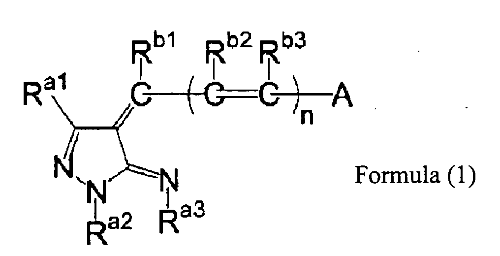
- In Formula (1) above, Ra1, Ra2, Ra3, Rb1, Rb2 and Rb3 each independently represent a hydrogen atom, or a monovalent substituent. The "monovalent substituent group" represented by Ra1, Ra2, Ra3, Rb1, Rb2 or Rb3 may be an substitutable group. The monovalent substituent group may include, for example, an aliphatic group, an aryl group, a heterocyclic group, an acyl group, an acyloxy group, an acylamino group, an aliphatic oxy group, an aryloxy group, a heterocyclic oxy group, an aliphatic oxycarbonyl group, aryloxycarbonyl group, a heterocyclic oxycarbonyl group, a carbamoyl group, an aliphatic sulfonyl group, an aryl sulfonyl group, a heterocyclic sulfonyl group, an aliphatic sulfonyloxy group, an arylsulfonyloxy group, a heterocyclic sulfonyloxy group, a sulfamoyl group, an aliphatic sulfonamide group, an aryl sulfonamide group, a heterocyclic sulfonamide group, an amino group, an aliphatic amino group, an aryl amino group, a heterocyclic amino group, an aliphatic oxycarbonyl amino group, an aryloxycarbonyl amino group, a heterocyclic oxycarbonyl amino group, an aliphatic sulfinyl group, an aryl sulfinyl group, an aliphatic thio group, an aryl thio group, a hydroxyl group, a cyano group, a sulfo group, a carboxyl group, an aliphatic oxyamino group, an aryl oxyamino group, a carbamoyl amino group, a sulfamoyl amino group, a halogen atom, a sulfamoyl carbamoyl group, a carbamoyl sulfamoyl group, a dialiphatic oxysulfinyl group, a diaryl oxyphosphinyl group, and the like. These substituents may further substituted with other monovalent substituents.
- Among the above, in light of the effect of the invention, it is preferable that Ra1, Ra2, Ra3, Rb1, Rb2 and Rb3 represent a hydrogen atom, an aliphatic group, an aryl group, an acyloxy group, an acylamino group, an aliphatic oxy group, an aliphatic sulfonyloxy group, an aryl sulfonyloxy group, an aliphatic sulfonamide group, an aryl sulfonamide group, an amino group, an aliphatic amino group, an aryl amino group, an aliphatic oxycarbonyl amino group, an aryloxycarbonyl amino group, a heterocyclic oxycarbonyl amino group, a hydroxyl group, a cyano group, a sulfo group, a carbamoyl amino group, or a sulfamoyl amino group, and, it is more preferable that these represent a hydrogen atom, an aliphatic group, an aryl group or an aliphatic oxy group. Ra2 and Ra3 may be bonded to each other to form a 5-membered to 7-membered ring structure.
- More preferable specific examples are as follows:
- Ra1 is preferably an alkyl group having 1 to 12 carbon atoms. For example, methyl group, ethyl group, i-propyl group, t-butyl group, cyclohexyl group, 2-ethylhexyl group, dodecyl group and the like. In particular, an alkyl group having 1 to 8 carbon atoms is preferable, and an alkyl group having 1 to 4 carbon atoms is more preferable.
- Ra2 is preferably an aliphatic group or an aryl group, and Ra3 is preferably a hydrogen atom or an aliphatic group, more preferably a hydrogen atom. Particularly preferably, Ra2 and Ra3 are bonded to each other to form a ring structure. The ring structure when a ring is formed is preferably 5-membered to 7-membered ring, and more preferably 5-membered ring.
- Rb1, Rb2 and Rb3 are preferably a hydrogen atom or an aliphatic group, and particularly preferable a hydrogen atom.
- In Formula (1), A represents a substituted or unsubstituted aliphatic group, a substituted or unsubstituted aryl group, a substituted or unsubstituted heterocyclic group. When A has a substituent, the substituents similar to the substituent listed for the "monovalent substituent" represented by Ra1- Ra3 and Rb1- Rb3 may be exemplified. Preferred examples thereof include a heterocyclic group, an acyl group, an acyloxy group, an acylamino group, an aliphatic oxy group, an aryloxy group, a heterocyclic oxy group, an aliphatic oxycarbonyl group, aryloxycarbonyl group, a heterocyclic oxycarbonyl group, a carbamoyl group, an aliphatic sulfonyl group, an aryl sulfonyl group, a heterocyclic sulfonyl group, an aliphatic sulfonyloxy group, an arylsulfonyloxy group, a heterocyclic sulfonyloxy group, a sulfamoyl group, an aliphatic sulfonamide group, an aryl sulfonamide group, a heterocyclic sulfonamide group, an aliphatic oxycarbonyl amino group, an aryloxycarbonyl amino group, a heterocyclic oxycarbonyl amino group, an aliphatic sulfinyl group, an aryl sulfinyl group, a hydroxyl group, a cyano group, a carboxyl group, a sulfamoyl amino group, a halogen atom, a sulfamoyl carbamoyl group, a carbamoyl sulfamoyl group and the like.
- As an unsbstituted aliphatic group, for example, an alkyl group having 1 to 20 carbon atoms in total, an alkenyl group having 2 to 20 carbon atoms in total and an alkynyl group having 2 to 20 carbon atoms in total are preferably exemplified. In particular, an alkyl group having 1 to 15 carbon atoms in total is preferable, and an alkyl group having 1 to 10 carbon atoms in total is particularly preferable.
As a sbstituted aliphatic group, for example, a substituted alkyl group having 2 to 20 carbon atoms in total, a substituted alkenyl group having 3 to 20 carbon atoms in total and a substituted aralkyl group having 7 to 20 carbon atoms in total are preferably exemplified. Among them, a substituted alkyl group having 2 to 15 carbon atoms in total is preferable, and a substituted alkyl group having 2 to 10 carbon atoms in total is particularly preferable. - An aryl group represented by A may be unsubstituted or substituted, or ring-condensed. For example, phenyl group, 4-methoxy phenyl group, 4-dimethylamino group and the like are exemplified. In particular, an aryl group having 6 to 30 carbon atoms in total is preferable, an aryl group having 6 to 20 carbon atoms in total is more preferable, an aryl group having 6 to 15 carbon atoms in total is further preferable, and an aryl group having 6 to 12 carbon atoms in total is most preferable.
- A heterocyclic group represented by A may be unsubstituted or substituted, or ring-condensed. A 5-membered to 7-membered substituted or unsubstituted heterocyclic group having 2 to 30 carbon atoms in total is preferred. Among them, A is preferably heterocycles referred to as acidic nuclei in the technical area of cyanine dyes and oxonole dyes. The acidic nuclei are described in "The theory of the Photographic Process", edited by James, 4th Edition, pp.198, published by McMillan Co., 1977. More specifically, pyrazole-5-one, prazolidine-3,5-dione, imidazoline-5-one, hydantoin, 2 or 4-thiohydantoin, 2-iminooxazolidine-4-one, 2-oxazoline-5-one, 2-thiooxazoline-2,4-dione, isorhodanine, rhodanine, thiophene-3-one, thiophene-3-one-1,1-dioxide, indoline-2-one, indoline-3-one, 2-oxoindazolium, 5,7-dioxo-6,7-dihydrothiazolo[3,2-a]pyrimidine, 3,4-dihydroisoquinoline-4-one, 1,3-dioxane-4,6-dione (for example, Meldrum's acid or the like), barbituric acid, 2-thiobarbituric acid, coumarin-2,4-dione, indazoline-2-one, pyrido[1,2-a]pyrimidine-1,3-dione, pyrazolo[1,5-b]quinazolone, pyrazolopyridone, nuclei such as 5-membered or 6-membered carbon rings (for example, hexane-1,3-dione, pentane-1,3-dione, indane-1,3-dione, or the like), each of which may be substituted, are exemplified. Pyrazole-5-one, barbituric acid, 2-thiobarbituric acid, 1,3-dioxane-4,6-dione are preferred. Further, moieties of compounds referred to as color couples in the area of the silver salt photographic technology are preferred.
For example, pyrazolones, 1H-imidazo[1,2-b]pyrazoles, 1H-pyrazolo[5-1-c][1,2,4]triazoles, 1H-pyrazolo[1,5-b][1,2,4]triazoles and the like are exemplified.
In particular, as A, 5-membered or 7-membered heterocyclic groups having 2 to 20 carbon atoms in total are more preferable. - Among the groups in the above, A is preferably a group represented by the following formulae (A-1) to (A14).


- In the above (A-1) to (A14), R6 to R49 each independently represent a hydrogen atom or a substituent. Here, the substituent is the group recited in the paragraph "monovalent substituent" as described in the above, and may be any substitutable group. Preferred substituents include an aliphatic group, an aryl group, a heterocyclic group, an acyl group, an acylamino group, an aliphatic oxy group, an aliphatic oxycarbonyl group, a carbamoyl group, a sulfamoyl group, an aliphatic sulfonamide group, an aryl sulfonamide group, an amino group, an aliphatic amino group, a hydroxyl group, a cyano group, a sulfo group and a carboxyl group.
- Adjacent two groups in R6 to R14, R15 to R17, R42 to R47, and R19 and R20, R21 and R22, R23 and R24, R29 and R30, R31 and R32, and R35 and R36 may be bonded to each other insofar as they can be bonded to each other to form a 5-membered to 7 membered hydrocarbon ring or heterocyclic ring.
- In addition, Q1 in (A-9), Q2 in (A-11) and Q3 in (A-14) each represent a non-metal atomic group necessary for forming a 5-membered to 7-membered ring.
- Among the above groups, in view of the effect of the invention, A preferably represents (A-10), (A-11) or (A-14), and particularly preferably represents (A-11).
- (A1-1 to A14-25) which are specific examples of A are shown below, but the invention is not limited to these examples:
-


-


-


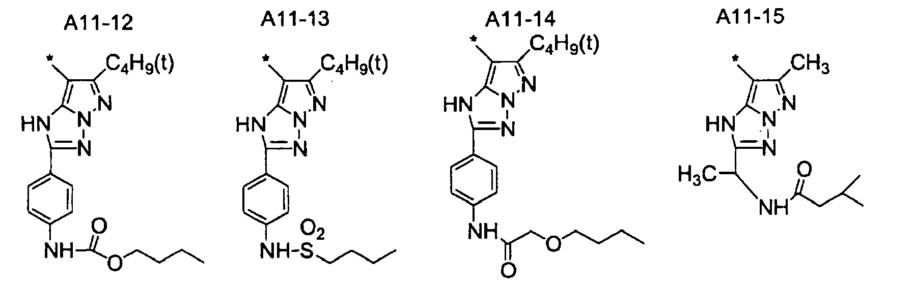
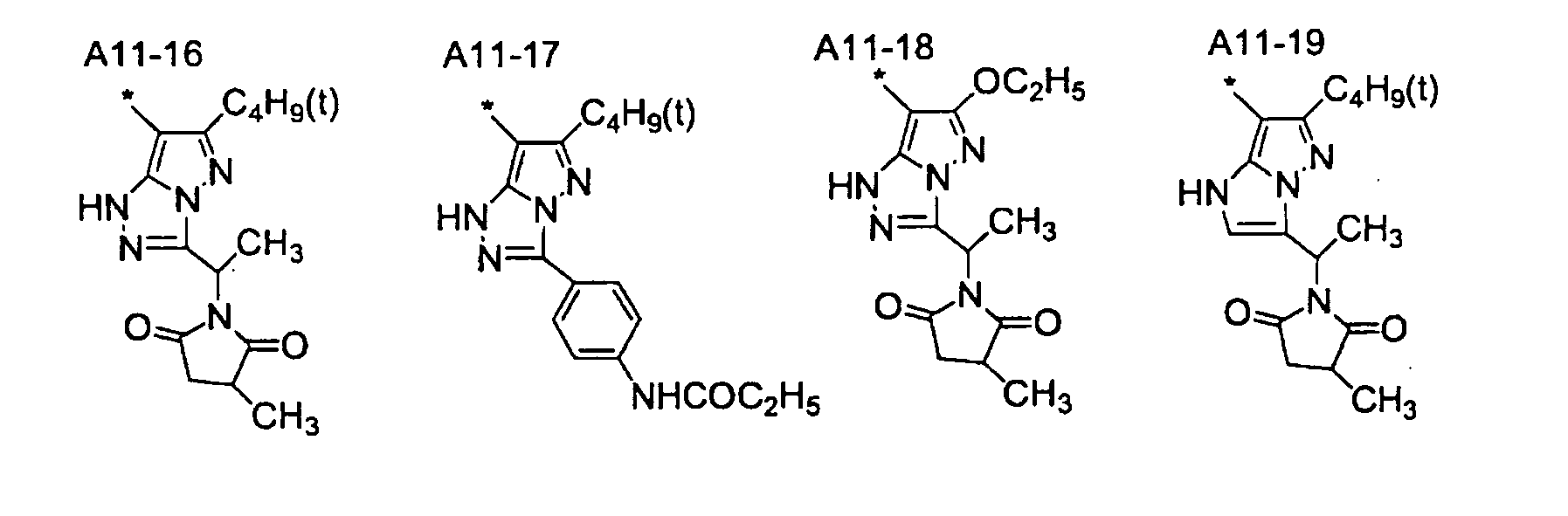
-
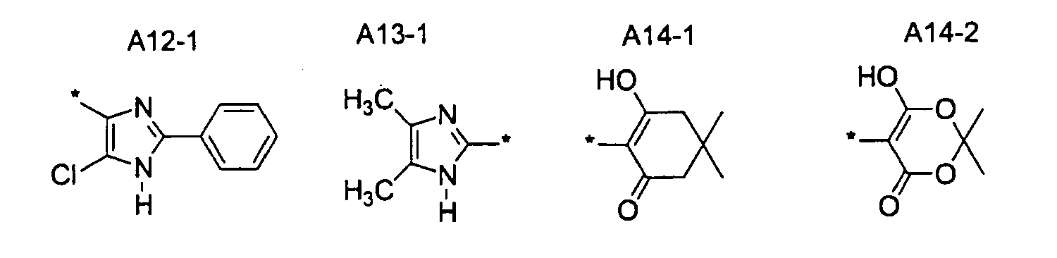


-

- In Formula (1), n represents 0, 1, 2 or 3. When n is 2 or more, plural occurrences of Rb2 may be the same or different and plural occurrences of Rb3 may be the same or different. In light of fastness, n is preferably0, 1 or 2, and more preferably 0 or 1.
- In Formula (1), specific examples (B10-1 to B10-8) of groups which have a pyrazoline ring as a basic structure to which Ra1 is bonded are shown. However, the invention is not limited to these examples.
-


- In Formula (1), it is particularly preferable that Ra1 is an alkyl group having 1 to 4 carbon atoms, Ra2 and Ra3 are bonded to each other to form a 5-membered to 7-membered ring, Rb1 is a hydrogen atom, Rb2 is a hydrogen atom, Rb3 is a hydrogen atom, A is (A-10), (A-11) or (A-14), and n is 0 or 1.
- The dye compound represented by Formula (1) may have either a symmetrical skeleton structure or asymmetrical skeleton structure with respect to a methine group at the center of the dye, but an azole ring represented by A has the same azole skeleton structure as the azole ring (pyrazoline ring) to which Ra1 is bonded, is preferred in light of fastness.
- Among the dye compounds represented by Formula (1), the dye compounds represented by Formula (2) below are more preferable.
-

- In Formula (2), Ra1, Rb1, Rb2 and Rb3 each independently represent a hydrogen atom, or a monovalent substituent. A represents a substituted or unsubstituted aliphatic group, a substituted or unsubstituted aryl group, or a substituted or unsubstituted heterocyclic ring group. n represents 0, 1, 2 or 3. When n is 2 or more, plural occurrences of Rb2 may be the same or different and plural occurrences of Rb3 may be the same or different. Here, in Formula (2), Ra1, Rb1, Rb2 and Rb3, A and n are the same as Ra1, Rb1, Rb2 and Rb3, A and n in Formula (1) as described above, and preferred embodiments thereof are the same as those.
- In Formula (2), Z represents a group forming a 5-membered to 7-membered heterocyclic ring together with a nitrogen atom or carbon atom.
- "The 5-membered to 7-membered heterocyclic ring" is a heterocyclic ring formed by a nitrogen atom and carbon atom which constitute the 2-pyrazoline ring represented by Formula (2), and Z. For example, a 5-membered ring such as 1, 2, 4-triazole ring and imidazole ring, a 6-membered ring such as triazine ring, pyrimidine ring and 1, 3-diazacyclohexane ring, and a 7-membered ring such as 1,3-diazacycloheptane are preferable, and 1, 2, 4-triazole ring is more preferable.
- "The 5-membered to 7-membered heterocyclic ring" may be unsubstituted or substituted. When substituted, the ring may be substituted with substituents similar to those enumerated in the paragraph of "monovalent substituent" represented by Ra1 to Ra3 or the like in Formula (1).
- Hereinafter, in Formula (2), specific examples (B11-1 - B11-19) of the groups which have a 5-membered to 7-membered heterocyclic ring including 2-pyrazoline ring, to which Ra1 is bonded, and Z, as a basic structure are enumerated. However, the invention is not limited to these examples.
-


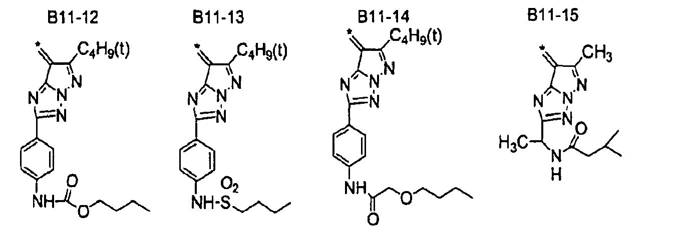

- Further, in the dye compounds represented by Formula (2), embodiments in which Ra1 is an alkyl group having 1 to 8 carbon atoms, the hererocyclic ring formed together with Z, a nitrogen atom and carbon atom is a 5-membered ring, Rb1, Rb2 and Rb3 are a hydrogen atom, and n is 0 or 1 are preferable, in particular, embodiments in which R a1 is an alkyl group having 1 to 4 carbon atoms, the hererocyclic ring formed together with Z, a nitrogen atom and carbon atom is 1,2,4-triazole ring, Rb1, Rb2 and Rb3 are hydrogen atoms, and n is 0 or 1, are more preferable
Furthermore, in light of improving fastness, it is particularly preferable that in the dye compound represented by Formula (2), the azole ring represented by A has the same azole skeleton structure as the azole ring (pyrazoline ring) to which Ra1 is bonded. - Among the dye compounds represented by Formula (2), the dye compounds represented by Formula (3) below are most preferable.
-

- In Formula (3), Ra1, Ra4, Rb1, Rb2 and Rb3 each independently represent a hydrogen atom, or a monovalent substituent. A represents a substituted or unsubstituted aliphatic group, a substituted or unsubstituted aryl group, or a substituted or unsubstituted heterocyclic ring group. n represents 0, 1, 2 or 3. When n is 2 or more, plural occurrences of Rb2 may be the same or different and plural occurrences of Rb3 may be the same or different. Here, in Formula (3), Ra1, Rb1, Rb2 and Rb3, A and n are the same as Ra1, Rb1, Rb2 and Rb3, A and n in Formula (1) as described above, and preferred embodiments thereof are the same as those.
- In Formula (3), Ra4 represents a hydrogen atom, or a monovalent substituent. The monovalent substituents represented by Ra4 may be any substitutable groups, and substituents similar to those enumerated in the paragraphs of "monovalent substituent" represented by Ra1 to Ra3 and Rb1 to Rb3 as described above can be enumerated.
The substituents may be unsubstituted, or further substituted with substituents enumerated in the paragraph of "monovalent substituent" represented by Ra1 to Ra3 or the like in Formula (1), preferably with an aliphatic group, aryl group, or heterocyclic group, more preferably, an alkyl group or aryl group. - The aliphatic groups represented by Ra4 may be unsubstituted or substituted, and include an alkyl group, alkenyl group and the like.
The unsubstituted or substituted alkyl group is preferably an alkyl group having 1 to 25 carbon atoms, for example, i-propyl group, 2-methyl-2-acetylaminoehyl group, 2-propanoyl aminopropyl group and the like are exemplified. In particular, an alkyl group having 2 to 25 carbon atoms is preferable, and an alkyl group having 2 to 20 carbon atoms is particularly preferable. - The aryl groups represented by Ra4 may be unsubstituted or substituted, and are preferably an aryl group having 6 to 30 carbon atoms, and more preferably an aryl group having 6 to 20 carbon atoms, and for example, 4-butanoyl aminophenyl group, 4-butane sulfonamide phenyl group, 4-nitrophenyl group and the like are preferably exemplified.
- The heterocyclic group represented by Ra4 may be unsubstituted or substituted, and for example, 5-pyrimidil group and the like are preferably exemplified.
- Further, in the dye compounds represented by Formula (3), embodiments in which Ra1 is an alkyl group having 1 to 8 carbon atoms, Ra4 is an alkyl group, or aryl group, Rb1 is a hydrogen atom, Rb2 is a hydrogen atom, Rb3 is a hydrogen atom, and n is 0 or 1 are preferable, and, in particular, embodiments in which Ra1 is an alkyl group having 1 to 4 carbon atoms, Ra4 is an alkyl group having 1 to 20 carbon atoms, or an aryl group having 6 to 20 carbon atoms, Rb1, Rb2 and Rb3 are hydrogen atoms, and n is 0 or 1, are more preferable
Furthermore, in light of improving fastness, it is particularly preferable that in the dye compound represented by Formula (3), the azole ring represented by A has the same azole skeleton structure as the azole ring (pyrazoline ring) to which Ra1 is bonded. - In the dye compounds represented by Formulae (1) to (3), when the dye compound contains an anion (when a proton is released from A), a cation which forms a pair therewith (counter ion) is preferably the cationic part in the compounds represented by the Formula (I), (II) or (III) as described in Japanese Patent Application Laid-Open (JP-A) No.
10-109475 - Hereinafter, specific examples of the dye compounds (exemplary compounds M-1 - M-52, T-1 - T-52, P-1 - P-52, and H-1 - H30) represented by Formulae (1) - (3) are shown. However, the invention is not limited thereto.
The numbers listed in the columns of the structural formula A and the structural formula B in the exemplary compounds show respectively, the number of the specific examples represented by A as described above, and the number of the specific examples of the groups which have a 5-membered to 7-membered heterocyclic ring having a pyrazole ring or 2-pyrazoline ring, which Ra1 is bonded, and Z, as a basic structure. -
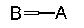
Exemplary Compound Structural Formula B Structural Formula A Exemplary Compound Structural Formula B Structural Formula A M - 1 B10 - 1 A11 - 7 M - 2 B10 - 2 A11 - 7 M - 3 B10 - 7 A11 - 7 M - 4 B11 - 1 A11 - 7 M - 5 B11 - 3 A11 - 7 M - 6 B11 - 5 A11 - 7 M - 7 B11 - 6 A11 - 7 M - 8 B11 - 7 A11 - 7 M - 9 B11 - 8 A11 - 7 M - 10 B11 - 15 A11 - 7 M - 11 B11 - 7 A1 - 1 M - 12 B11 - 7 A2 - 3 M - 13 B11 - 7 A3 - 1 M - 14 B11 - 7 A4 - 2 M - 15 B11 - 7 A5 - 2 M - 16 B11 - 7 A6 - 1 M - 17 B11 - 7 A7 - 1 M - 18 B11 - 7 A8 - 2 M - 19 B11 - 7 A9 - 1 M - 20 B11 - 7 A10 - 2 M - 21 B11 - 7 A10 - 9 M - 22 B11 - 7 A10 - 10 M - 23 B11 - 7 A10 - 12 M - 24 B11 - 7 A11 - 1 M - 25 B11 - 7 A11 - 8 M - 26 B11 - 7 A11 - 11 M - 27 B11 - 7 A11 - 15 M - 28 B11 - 7 A14 - 3 M - 29 B11 - 7 A14 - 7 M - 30 B11 - 7 A14 - 8 M - 31 B11 - 7 A14 - 9 M - 32 B11 - 7 A14 - 12 M - 33 B11 - 7 A14 - 14 M - 34 B11 - 7 A14 - 21 M - 35 B11 - 5 A10 - 9 M - 36 B11 - 5 A10 - 10 M - 37 B11 - 5 A10 - 12 M - 38 B11 - 5 A10 - 15 M - 39 B11 - 5 A11 - 3 M - 40 B11 - 5 A11 - 5 M - 41 B11 - 5 A14 - 4 M - 42 B11 - 5 A14 - 9 M - 43 B11 - 5 A14 - 10 M - 44 B11 - 5 A14 - 21 M - 45 B10 - 2 A10 - 2 M - 46 B11 - 8 A11 - 8 M - 47 B11 - 12 A11 - 12 M - 48 B11 - 6 A11 - 6 M - 49 B11 - 10 A11 - 10 M - 50 B11 - 11 A11 - 11 M - 51 B11 - 15 A11 - 15 M - 52 B11 - 13 A11 - 13 -

Exemplary Compound Structural Formula B Structural Formula A Exemplary Compound Structural Formula B Structural Formula A T - 1 B10 - 1 A11 - 7 T - 2 B10 - 2 A11 - 7 T - 3 B10 - 7 A11 - 7 T - 4 B11 - 1 A11 - 7 T - 5 B11 - 3 A11 - 7 T - 6 B11 - 5 A11 - 7 T - 7 B11 - 6 A11 - 7 T - 8 B11 - 7 A11 - 7 T - 9 B11 - 8 A11 - 7 T - 10 B11 - 15 A11 - 7 T - 11 B11 - 7 A1 - 1 T - 12 B11 - 7 A2 - 3 T - 13 B11 - 7 A3 - 1 T - 14 B11 - 7 A4 - 2 T - 15 B11 - 7 A5 - 2 T - 16 B11 - 7 A6 - 1 T - 17 B11 - 7 A7 - 1 T - 18 B11 - 7 A8 - 2 T - 19 B11 - 7 A9 - 1 T - 20 B11 - 7 A10 - 2 T - 21 B11 - 7 A10 - 9 T - 22 B11 - 7 A10 - 10 T - 23 B11 - 7 A10 - 12 T - 24 B11 - 7 A11 - 1 T - 25 B11 - 7 A11 - 8 T - 26 B11 - 7 A11 - 11 T - 27 B11 - 7 A11 - 15 T - 28 B11 - 7 A14 - 3 T - 29 B11 - 7 A14 - 7 T - 30 B11 - 7 A14 - 8 T - 31 B11 - 7 A14 - 9 T - 32 B11 - 7 A14 - 12 T - 33 B11 - 7 A14 - 14 T - 34 B11 - 7 A14 - 21 T - 35 B11 - 5 A10 - 9 T - 36 B11 - 5 A10 - 10 T - 37 B11 - 5 A10 - 12 T - 38 B11 - 5 A10 - 15 T - 39 B11 - 5 A11 - 3 T - 40 B11 - 5 A11 - 5 T - 41 B11 - 5 A14 - 4 T - 42 B11 - 5 A14 - 9 T - 43 B11 - 5 A14 - 11 T - 44 B11 - 5 A14 - 21 T - 45 B10 - 2 A10 - 2 T - 46 B11 - 8 A11 - 8 T - 47 B11 - 12 A11 - 12 T - 48 B11 - 6 A11 - 6 T - 49 B11 - 10 A11 - 10 T - 50 B11 - 11 A11 - 11 T - 51 B11 - 15 A11 - 15 T - 52 B11 - 13 A11 - 13 -

Exemplary Compound Structural Formula B Structural Formula A Exemplary Compound Structural Formula B Structural Formula A P - 1 B10 - 1 A11 - 7 P - 2 B10 - 2 A11 - 7 P - 3 B10 - 7 A11 - 7 P - 4 B11 - 1 A11 - 7 P - 5 B11 - 3 A11 - 7 P - 6 B11 - 5 A11 - 7 P - 7 B11 - 6 A11 - 7 P - 8 B11 - 7 A11 - 7 P - 9 B11 - 8 A11 - 7 P - 10 B11 - 15 A11 - 7 P - 11 B11 - 7 A1 - 1 P - 12 B11 - 7 A2 - 3 P - 13 B11 - 7 A3 - 1 P - 14 B11 - 7 A4 - 2 P - 15 B11 - 7 A5 - 2 P - 16 B11 - 7 A6 - 1 P - 17 B11 - 7 A7 - 1 P - 18 B11 - 7 A8 - 2 P - 19 B11 - 7 A9 - 1 P - 20 B11 - 7 A10 - 2 P - 21 B11 - 7 A10 - 9 P - 22 B11 - 7 A10 - 10 P - 23 B11 - 7 A10 - 12 P - 24 B11 - 7 A11 - 1 P - 25 B11 - 7 A11 - 8 P - 26 B11 - 7 A11 - 11 P - 27 B11 - 7 A11 - 15 P - 28 B11 - 7 A14 - 3 P - 29 B11 - 7 A14 - 7 P - 30 B11 - 7 A14 - 8 P - 31 B11 - 7 A14 - 9 P - 32 B11 - 7 A14 - 12 P - 33 B11 - 7 A14 - 14 P - 34 B11 - 7 A14 - 21 P - 35 B11 - 5 A10 - 9 P - 36 B11 - 5 A10 - 10 P - 37 B11 - 5 A10 - 12 P - 38 B11 - 5 A10 - 15 P - 39 B11 - 5 A11 - 3 P - 40 B11 - 5 A11 - 5 P - 41 B11 - 5 A14 - 4 P - 42 B11 - 5 A14 - 9 P - 43 B11 - 5 A14 - 11 P - 44 B11 - 5 A14 - 21 P - 45 B10 - 2 A10 - 2 P - 46 B11 - 8 A11 - 8 P - 47 B11 - 12 A11 - 12 P - 48 B11 - 6 A11 - 6 P - 49 B11 - 10 A11 - 10 P - 50 B11 - 11 A11 - 11 P - 51 B11 - 15 A11 - 15 P - 52 B11 - 13 B11 - 13 -


-


- The synthesis of the dye compounds represented by the Formulae (1) - (3) can be conducted by a method similar to that of Patent No.
3707759 - The content of the dye compounds represented by the Formulae (1) - (3) (dye according to the invention) in the visible information recording layer is preferably 5 to 100% by mass relative to the total solid content in the recording layer. The content of the dye according to the invention in the above range is effective in view of recording an image with high contrast and enhancing light fastness of a recorded image.
- In the visible information recording layer of the invention, in light of increasing and controlling the contrast of a recorded image, other dyes such as a cyanine dye, phthalocyanine dye, an azo dye, an azo metal complex, an oxonol dye and a leuco type dye may be used in combination with the dye according to the invention.
- In addition to the above, a binder and various kinds of additives such as an anti-fading agent, an ultraviolet absorber, a plasticizer, a lubricant and the like can be contained in the visible information recording layer, in accordance with the intended use.
- Examples of the binder, as the same as the above, include natural organic polymer substances such as gelatin, cellulose derivatives, dextran, rosin, rubber and the like, synthetic organic polymers such as hydrocarbon type resins such as polyethylene, polypropylene, polystyrene, polyisobutylene and the like; vinyl type resin such as polyvinyl chloride, polyvinylidene chloride, polyvinyl chloride/polyvinyl acetate copolymer and the like; acrylic resins such as polymethyl acrylate, polymethyl methacrylate and the like; polyvinyl alcohol, chlorinated polyethylene, epoxy resin, butylal resins, rubber derivatives, initial condnsates of thermosetting resins such as phenol/formaldehyde resin, and the like.
- When a binder is contained, in general, the amount of the binder is preferably in the range of from 0.01 to 50 times, and more preferably in the range of from 0.1 to 5 times the total amount of a dye.
- For the purpose of enhancing the light fastness, various kinds of ant-fading agents may be contained. A singlet oxygen quencher is generally used as the anti-fading agent. The singlet oxygen quencher may suitably be selected from known materials, and examples thereof include those described in
JP-A Nos. 58-175693 59-31194 60-18387 60-19586 60-19587 60-305054 60-36190 60-36191 60-44554 60-44555 60-44389 60-44390 60-54892 60-47069 68-209995 4-25492 1-38680 6-26028 350399 , and the Journal of the Chemical Society of Japan, pp. 1141, 1992 (10). - An amount of the anti-fading agent as the singlet oxygen quencher is generally in the range of 0.1% by mass to 100% by mass, preferably in the range of 0.5% by mass to 75% by mass, more preferably in the range of 3% by mass to 50% by mass, most preferably in the range of 5% by mass to 50% by mass relative to the total amount of the dye.
- The visible information recording layer can be formed by coating a coating liquid prepared by dissolving the dye according to the invention, and if necessary, other dyes and various kinds of additives (antioxidants, ultraviolet absorbers, plasticizers, lubricants and the like) in a solvent.
- Examples of the solvent for the preparation include esters such as butyl acetate, ethyl lactate and cellosolve acetate; ketones such as methyl ethyl ketone, cyclohexanone and methyl isobutyl ketone; chlorinated hydrocarbons such as dichloromethane, 1,2-dichloroethane and chloroform; amides such as dimethyformamide; hydrocarbons such as methycyclohexane; ethers such as dibutyl ether, diethyl ether, tetrahydrofuran, dioxane; alcohols such as ethanol, n-propanol, isopropanol, n-buthanol and diacetone alcohol; fluorinated solvents such as 2,2,3,3-tetrafluoropropanol; and glycol ethers such as ethylene glycol monomethyl ether, ethylene glycol monoethyl ether and propylene glycol monomethyl ether.
The solvent may be used by itself or in a combination of two or more thereof, in view of the solubility of the dye used. - Coating can be carried out by known coating methods such as a spray method, a spin coating method, a dip method, a roll coat method, a blade coat method, a doctor roll method and a screen printing method.
- The thickness of the visible information recording layer is preferably 0.01 to 50 µm, more preferably 0.02 to 20 µm, and further more preferably 0.03 to 5 µm. The visible information recording layer may be either a single layer or multi-layers.
- The dye according to the invention represented by Formula (1), as described hereinafter, is effective for the use of materials for forming the visible information recording layer in which visible information is recorded by irradiating the layer with laser beam which sways in a radial direction and on the substantially same tracks plural times.
- The substrate for forming the optical recording medium of the invention is a substrate (corresponding to the
denotation 16, for example, inFig. 1 , hereinafter, may be referred to as "first substrate") which is closer to a digital information recording layer, which will be described later, than the visible information recording layer. The substrate may be selected from various kinds of materials which are used as substrates for optical recording media. - Materials for the substrate include, for example, glass, and acrylic resins such as polycarbonate and polymethyl methacrylate; vinylchloride type resins such as polyvinylchloride and vinylchloride copolymer; epoxy resins, amorphous polyolefin, polyester and the like. If necessary, the materials may be used in combination. These materials may be used as a film-like substrate or a rigid substrate. Among these materials, polycarbonate is preferred in view of the moisture resistance, dimension stability and cost thereof.
The thickness of the first substrate is preferably 0.05 to 1.2 mm, and more preferably 0.1 to 1.1 mm.
Guide grooves for tracking, or micro-asperities (pre-groove) for representing information such as address signals are formed on the first substrate. - In the case of DVD-R or DVD-RW, it is preferable that the track pitch of the pre-grooves is in the range of from 300 to 900nm, more preferably from 350 to 850nm and further preferably from 400 to 800nm.
- The depth of the pre-grooves (i.e., the groove depth) preferably is in the range of from 100 to 160 nm, more preferably in the range of from 120 to 150 nm and further preferably in the range of from 130 to 140 nm. Further, the groove width (i.e., half-value width) of the pre-grooves preferably is in the range of from 200 to 400 nm, more preferably in the range of 230 to 380 nm and further preferably in the range of from 250 to 350 nm.
- Meanwhile, a substrate with grooves having a narrower track pitch as compared to those of conventional DVD-Rs and the like can be used in order to achieve even higher recording density. In this case, the track pitch of the grooves is preferably in the range of from 280 to 450 µm, more preferably in the range of from 300 to 420 nm and further preferably in the range of from 320 to 400 nm. Further, the depth of the grooves (i.e., groove depth) is preferably in the range of from 15 to 150 nm and still more preferably in the range of from 25 to 100 nm. Further, the groove width of the grooves is preferably in the range of from 50 to 250 nm and further preferably in the range of from 100 to 200 nm.
- In the case of CD-Rs and the like, the track pitch of the grooves is preferably in the range of from 1.2 to 2.0 µm, more preferably in the range of from 1.4 to 1.8 µm, and still more preferable in the range of from 1.55 to 1.65 µm. The depth of the grooves (i.e., the groove depth) preferably is in the range of from 100 to 250 nm, more preferably in the range of from 150 to 230 nm and further preferably in the range of from 170 to 210 nm. The groove width of the pre-grooves preferably is in the range of from 400 to 650 nm, more preferably in the range of from 480 to 600 nm and still more preferably in the range of from 500 to 580 nm.
- As described in the above, the visible information recording layer containing the dye compound represented by Formula (1) is suitably constituted for a visible information recording layer wherein the visible information recording layer is irradiated by a laser beam multiple times along substantially same track to record the visible information. Further, the visible information recording layer is preferably constituted such that when the visible information recording layer containing the dye compound represented by Formula (1) is irradiated by a laser beam multiple times overlappingly on the substantially same track to record the visible information, the laser beam is swayed in a radial direction to record the visible information. When a record is performed by irradiating a recording layer with laser beam multiple times overlappingly on the substantially same track to record the visible information, or when laser beam is swayed in a radial direction multiple times overlappingly on the substantially same track to record the visible information, an image with a high contrast and sharpness can be obtained, and an image light fastness is increased.
- For the purpose of improving flatness, enhancing adhesiveness and preventing deterioration of the recording layer, an undercoat layer may be provided at the side (the surface side on which the groove is formed) where the digital information recording layer is disposed on the first substrate.
- Examples of materials of the undercoat layer include polymer materials such as polymethyl methacrylate, acrylic acid/methacrylic acid copolymers, styrene/maleic anhydride copolymers, polyvinyl alcohol, N-methylol acrylamide, styrene/vinyltoluene copolymers, chlorosulfonated polyethylene, nitrocellulose, polyvinyl chloride, chlorinated polyolefin, polyester, polyimide, vinyl acetate/vinyl chloride copolymers, ethylene/vinyl acetate copolymers, polyethylene, polypropylene, and polycarbonate; and surface modifiers such as silane coupling agents.
The undercoat layer may be formed by dissolving or dispersing the materials in an appropriate solvent to prepare a coating liquid, and then coating the coating liquid on the surface of the substrate by known coating methods such as spin coating, dip coating, or extrusion coating.
The thickness of the undercoat layer is generally in the range of from 0.005 to 20 µm, preferably in the range of from 0.01 to 10 µm. - The optical recording medium of the invention may be appropriately constituted by providing other layers such as a digital information recording layer, a reflection layer, and an adhesive layer, and further a second substrate, in addition to the visible information recoding layer and the substrate (the first substrate).
- In the optical recording medium of the invention, the constituent components of the visible information recording layer may be the same as or different from the constituent components (dyes or phase change recording materials) of a digital information recording layer, which will be described later, but, the characteristics required for the visible information recording layer and the characteristics required for the digital information recording layer are different from each other, and accordingly, the constituent components for each layer are preferably different from each other. More specifically, it is preferable that the constituent components of the digital information recording layer impart a superior recording and reproducing characteristic, and the constituent components of the visible information recording layer impart a high image contrast.
- The optical recording medium of the invention may be provided with the digital information recording layer for recording signal information (coded information) such as digital information including music data and the like together with the visible information recording layer. For example, the digital information recording layer may be provided, through a reflection layer which reflects light during recording, at the opposite side of the visible information recording layer.
- The digital information recording layer is a layer which records and reproduces electronic information by means of laser beam used for recording and reproducing, and may be either a dye recording layer or a phase change type recording layer. However, a dye type recording layer containing a dye as a recording material is preferable.
- Specific examples of the dyes contained in the dye type information recording layer include cyanine dyes, oxonol dyes, azo dyes, phthalocyanine dyes, triazole compounds (including benzotriazole compounds), triazine compounds, merocyanine compounds, aminobutadiene compounds, cinnamic acid compounds, benzoxazole compound, pyromethene compounds and squarylium compound. These compounds may have a metal atom at the coordinate center thereof. The dyes described in
JP-A Nos. 4-74690 8-127174 11-53758 11-334204 11-334205 11-334206 11-334207 2000-43423 2000-108513 2000-158818 - Among these dyes, (1) in the case where a CD-R or CD-RW (CD type) is formed by the optical recording medium of the invention, cyanine dyes, azo dyes and phthalocyanine dyes are preferably used; (2) in the case where a DVD-R or DVD-RW (DVD type) is formed, cyanine dyes, oxonol dyes, azo dyes (including Ni and Co complexes) and pyromethene compounds are preferably used, and (3) in the case where a Blu-ray disk is formed, cyanine dyes, oxonol dyes, azo dyes, phthalocyanine dyes, benzotriazole compounds and triazine compounds are preferably used. Furthermore, among the above, in particular, (2) in the case where a DVD type is formed, cyanine dyes, oxonol dyes or azo dyes (including Ni and Co complexes) are preferable, and (3) in the case where a Blu-ray disk is formed, cyanine dyes, oxonol dyes, azo dyes and phthalocyanine dyes are preferable.
- In addition to the above, in the digital information recording layer, a binder and various kinds of additives such as an antioxidant, an ultraviolet absorber, a plasticizer, a lubricant and the like can be contained, in accordance with the intended use. Details of examples and amounts of the binder, and details of examples and amounts of the additives are the same as the descriptions in the visible information recording layer in the above.
- The digital information recording layer may be formed, for example, by vapor deposition, sputtering, CVD, or solvent coating, in particular, the solvent coating is preferable. When the solvent coating is used, a coating liquid is prepared by dissolving a recording material such as a dye, if necessary, together with a quencher, a binder, and the like, in a solvent, and the coating liquid is coated on a substrate, and the resultant coated layer is dried to form the digital recording layer.
- As the solvent for preparing the coating liquid, solvents similar to the solvents usable for preparing the coating liquid for forming the visible information recording layer, may be used. In this case, in view of the solubility of the dye, the solvents may be used singly, or two or more kinds in combination. Further, a binder and various kinds of additives such as an antioxidant, an ultraviolet absorber, a plasticizer, a lubricant and the like may be added to the coating solution in accordance with the intended use.
- The concentration of the recording material in the coating liquid is generally in the range of from 0.01 to 15 % by mass, preferably 0.1 to 10 % by mass, more preferably 0.5 to 5 % by mass, and most preferably 0.5 to 3 % by mass.
- The coating can be performed by the coating method similar to the coating method for forming the visible information recording layer. The digital information recording layer may be either a single layer or multiple layers. The thickness of the digital information recording layer is preferably in the range of from 10 to 500 nm, more preferably 15 to 300 nm and further more preferably 20 to 150 nm.
- In the digital information recording layer, various kinds of anti-fading agents may be contained in order to enhance the light fastness. A singlet oxygen quencher is generally used as the anti-fading agent. Details of the singlet oxygen quencher are described in the above. The preferable content range of the anti-fading agent such as the singlet oxygen quencher is the same as the descriptions in the visible information layer in the above.
- In the case where the digital information recording layer is a phase change type, the layer contains preferably an optical recording material comprising at least Ag, Al, In, Te, and Sb which can assume at least two states of a crystal state and an amorphous state. Such a layer may be formed by known methods. A known dielectric layer is preferably formed on this layer, if necessary.
- It is preferred that the reflection layer is formed for the purpose of improving reflectance during information reproduction at the inside adjacent to the digital information recording layer and/or the visible information recording layer.
Light-reflective materials as the materials for the reflection layer are preferably materials having a high reflectance to laser beam. Examples thereof include metals and semimetals such as Mg, Se, Y, Ti, Zr, Hf, V, Nb, Ta, Cr, Mo, W, Mn, Re, Fe, Co, Ni, Ru, Rh, Pd, Ir, Pt, Cu, Ag, Au, Zn, Cd, Al, Ga, In, Si, Ge, Te, Pb, Po, Sn, and Bi; stainless steel, and semiconductor materials. These materials may be used alone, in combination of two or more, or as an alloy. Among them, Cr, Ni, Pt, Cu, Ag, Au, Al and stainless steel are preferable. Metal Au, metal Ag, metal Al or alloys thereof are still more preferable, and Ag alloys (particularly Ag-Nd-Cu and Ag-Pd-Cu) are most preferable.
The reflection layer can be prepared, for example, by depositing, sputtering or ion plating the light-reflective substance on the substrate, digital information recording layer or visible information recording layer. The thickness of the reflection layer is generally in the range of from 10 to 300 nm and preferably in the range of from 50 to 200 nm. - When a laminated-type optical recording medium such as a DVD or the like is prepared, an adhesive layer can be formed by the process of adhering laminated bodies to each other, or a laminated body including a first substrate and a second substrate to each other. Materials for constituting an adhesive layer are preferably photocurable resins, in particular, resins having a low cure contraction rate, in light of preventing the warp of the disk.
Examples of such a photocurable resin include SD-640 and SD-661 manufactured by Dainippon Ink and Chemicals, Inc., and SK6100, SK6300, and SK6400 manufactured by Sony Chemicals Corp.
In order to impart the adhesive layer to elasticity, the thickness of the adhesive layer is in the range of from 1 to 100 µm, more preferably range in the range of from 5 to 60 µm, and particularly preferably in the range of from 20 to 55µm. - A protective layer may be provided, if necessary, in the optical recording medium of the invention, in order to prevent permeation of moisture or occurrence of scratches.
Examples of the materials used in the protective layer include preferably an ultraviolet ray curable resin, visible light curable resin, thermosetting resin, silicon dioxide and the like, and in particular, an ultraviolet ray curable resin is preferable. Examples of the ultraviolet ray curable resins include SD640 and the like manufactured by Dainippon Ink and Chemicals, Inc. SD-347 manufactured by Dainippon Ink and Chemicals, Inc., SD-694 manufactured by Dainippon Ink and Chemicals, Inc., SKCD1051 manufactured by SKC Co., and the like may also be used.
The thickness of the protective layer is preferably in the range of from 1 to 200 µm, more preferably in the range of from 50 to 150 µm. - In the laminated-type optical recording medium, a second substrate (may also be referred to as dummy substrate or protective substrate) is provided, through the visible information recording layer and the digital information recording layer and the like, in the face of the substrate (the first substrate) described in the above.
- The second substrate of the invention is mainly a substrate disposed at a closer position to the visible information recording layer than the position to the digital information recording layer. As the materials, the same materials as those for the first substrate in the above can be used. It is not necessary to provide groove on the surface side on which the visible information recording layer is formed.
- The thickness of the second substrate is preferably in the range of from 0.05 to 1.2 mm, more preferably in the range of from 0.05 to 1.1 mm, and still more preferably in the range of from 0.5 to 0.7 mm.
- As described hereinafter, for example, a cover layer or a transparent sheet may be used as a second substrate in such a constitution that a digital information recording layer, a reflection layer, a visible information recording layer and a cover layer on the first substrate in this order from the substrate is used.
- The cover layer is formed to prevent an interior of an optical recording medium from shock, and is not limited to a specific material as long as the material is transparent, but preferably, polycarbonate, cellulose triacetate and the like, and more preferably, a material having a hygroscopic rate at 23°C and 50% RH. Here, "transparent" means a degree of light transmittance of a material through which light for recording and reproducing can pass, preferably, 90% or higher.
- The cover layer may be formed by coating a coating liquid prepared by dissolving a photocurable resin for forming the adhesive layer in an appropriate solvent on a recording layer at a predetermined temperature to form an adhesive film, and on the adhesive film, laminating a cellulose triacetate film (TAC film) formed by, for example, a plastic extrusion process, and curing the adhesive film by irradiating with light from the above of the laminated TAC film. The TAC film contains preferably an ultraviolet absorber.
The thickness of the cover layer is preferably in the range of from 0.01 to 0.2 mm, more preferably in the range of from 0.03 to 0.1 mm, and particularly preferably in the range of from 0.05 to 0.095 mm. - A transparent sheet may be provided, and a polycarbonate sheet and the like may be used as the transparent sheet. The thickness of the transparent sheet is also preferably in the range of from 0.01 to 0.2 mm, more preferably in the range of from 0.03 to 0.1 mm, and particularly preferably in the range of from 0.05 to 0.095 mm. In the case that an adhesive is applied on the surface on which the transparent sheet is laminated, the adhesive layer in the above is not required. In addition to the above, a light transmittable layer containing an ultraviolet ray curable resin and the like may be formed as the cover layer.
- Further, a hard coat layer may be formed on the cover layer. The hard coat layer may be formed on a cover layer by means of coating or the like after the cover layer is laminated on a layer such as a reflection layer or a recording layer (including a visible information recording layer and a digital information recording layer) formed on a substrate. When a transparent sheet is used, before the transparent sheet is laminated on the recording layer, a hard coat layer is formed on the transparent sheet, and the transparent sheet is laminated on the recording layer such that the hard coat layer becomes the uppermost layer, so that the optical recording medium of the invention can be produced.
- Next, the constitution of the optical recording medium of the invention is described in detail.
The constitution of the optical recording medium of the invention, firstly, a DVD type constitution (including a DVD-R, HD-DVD and the like) is exemplified. For example, a constitution, in which a first substrate formed a digital information recording layer thereon and a second substrate formed a visible information recording layer thereon are laminated to each other via an adhesive layer, is exemplified. - The second substrate, in addition to the substrate formed on the opposite side of the first substrate via the digital information recording layer, the visible information recording layer and the like, includes the cover layer and the transparent sheet, as described above. Accordingly, as another constitution of the optical recording medium of the invention, a CD type constitution (including a CD-R) is exemplified. This is a constitution in which a digital information recording layer, a visible information recording layer and a cover layer on a substrate in this order from the substrate (first substrate) are formed on the substrate. Further, the optical recording medium of the invention may be a constitution of a Blu-ray disk.
-
Fig. 1 shows an example a schematic cross-sectional view of a DVD type optical recording medium of the invention.
As shown inFig. 1 , the DVD type optical recording medium may have a constitution, for example, in which afirst substrate 16, a digitalinformation recording layer 18 formed on thefirst substrate 16, a first reflection layer 20 formed on the digitalinformation recording layer 18, an adhesive layer 24 formed on the first reflection layer 20, a second reflection layer 24 formed on the adhesive layer 22, a visibleinformation recording layer 14 formed on the second reflection layer 24, and asecond substrate 26 formed on the visibleinformation recording layer 14. In this case, for example, thefirst substrate 16 having the digitalinformation recording layer 18 and the first reflection layer 20 formed thereon, and thesecond substrate 26 having the visibleinformation recording layer 14 and the second reflection layer 22 formed thereon are laminated together via the adhesive layer 22 so as to face the respective reflection layers each other. - When digital information is recorded on the DVD type optical recording medium of the invention, or when recorded digital information is reproduced, the optical recording medium is irradiated by a laser beam having a prescribed wavelength (in the case of a DVD-R, from 650 to 670 nm, and in the case of HD DVD, from 400 to 410 nm) from the
first substrate 16 side. - Further, when a visible image is recorded on the visible
information recording layer 14, the layer is irradiated with a prescribed laser beam (for example, laser beam having a linear velocity of 3.5 m/s, wavelength of 660 nm, NA = 0.6, and 10 mW at the disk surface) from thesecond substrate 26 side to modify the irradiated portion with the irradiation to change the contrast so that a visually recognizable visible image can be formed. In this way, since an image can be formed by using laser beam, a desired image recording can easily performed on a label surface (visible information recording layer) of the optical recording medium by means of an optical recording medium drive without providing with a printer or the like, separately. Further, the recorded image has a high contrast and an excellent visibility, and a high light-fastness with a high fading resistance even if exposed to light over a long period of time. - When the optical recording medium is formed as a CD type, as the laminated structure shown in
Fig. 1 , the optical recording medium can be constituted such that a digitalinformation recording layer 18 and a first reflection layer 20 are formed on afirst substrate 16 in this order from thesubstrate 16 side, a protective layer is formed on the reflection layer 20 in place of the adhesive layer 22, a second reflection layer 24 and a visibleinformation recording layer 14 are formed on the protective layer in this order, and a cover layer is formed on the visibleinformation recording layer 14 in place of thesecond substrate 26. In this constitution, an image having a high contrast and superior visual recognition can also be recorded, and the recorded image has a high light-fastness. - When digital information is optically recorded on the CD type optical recording medium, or when recorded digital information is reproduced, the optical recording medium is irradiated by a laser beam having a prescribed wavelength (for example, wavelength of about 600 nm) from the
first substrate 16 side.
Further, when a visible image is recorded on the visibleinformation recording layer 14 of the CD type optical recording medium, the layer is irradiated with a prescribed laser beam as described above from the cover layer side to modify the irradiated portion with the irradiation to change the contrast so that a visually recognizable visible image can be formed. In this way, since an image can be formed by using laser beam, a desired image recording can easily performed on a label surface (visible information recording layer) of the optical recording medium by means of an optical recording medium drive without providing with a printer or the like, separately. Further, the recorded image has a high contrast and an excellent visibility, and a high light-fastness with a high fading resistance even if exposed to light over a long period of time. - Moreover, the layer constitution shown in
Fig. 1 is an example. The order of the layer constitution may be not only the illustrated order in the drawing, but also another order in which the order of some of the layers is changed, and may be provided with other known layers. For example, the layer constitutions of the following (1) to (5) are exemplified: - (1) a first layer constitution is, for example, as shown in
Fig. 1 , a constitution such that a digitalinformation recording layer 18, a first reflection layer 20, an adhesive layer 22 and a second reflection layer 24 are formed on afirst substrate 16 in this order, and a visibleinformation recording layer 14 and asecond substrate 26 are formed on the second reflection layer 24; - (2) a second layer constitution is, not illustrated, a constitution such that a digital
information recording layer 18, a first reflection layer 20 and an adhesive layer 22 are formed on afirst substrate 16 in this order, and a visibleinformation recording layer 14 and asecond substrate 26 are formed on the adhesive layer 22; - (3) a third layer constitution is, not illustrated, a constitution such that a digital
information recording layer 18, a first reflection layer 20, a protective layer and an adhesive layer 22 are formed on afirst substrate 16 in this order, and a visibleinformation recording layer 14 and asecond substrate 26 are formed on the adhesive layer 22; - (4) a fourth layer constitution is, not illustrated, a constitution such that a digital
information recording layer 18, a first reflection layer 20, a first protective layer, an adhesive layer 22 and a second protective layer are formed on afirst substrate 16 in this order, and a visibleinformation recording layer 14 and asecond substrate 26 are formed on the second protective layer; and - (5) a fifth layer constitution is constitution such that a digital
information recording layer 18, a first reflection layer 20, a first protective layer, layer an adhesive layer 22, a second protective and a second reflection layer 24 are formed on afirst substrate 16 in this order, and a visibleinformation recording layer 14 and asecond substrate 26 are formed on the second reflection layer 24. - The optical recording medium of the invention may be any one of a read only type, a write once type or a rewritable type, but a write once type is preferable. In the case of a write once type, the recording methods are not specifically limited to, but may be any one of a phase change type, magneto-optical type, dye type and the like, and the dye type is preferable as described above.
- The method of producing the optical recording medium of the invention is described taking a DVD type optical recording medium as an example (see
Fig. 1 ). That is, the optical recording medium is produced by the process in which a first layer-forming step for laminating, on one side of afirst substrate 16, a digitalinformation recording layer 18 and a first reflection layer 20 in this order from thesubstrate 16 side, and a second layer-forming step for laminating, on one side of asecond substrate 26, a visibleinformation recording layer 14 and a second reflection layer 24 in this order from thesubstrate 26, and a step for adhering thefirst substrate 16 and thesecond substrate 26 to each other such that the digitalinformation recording layer 18 and the visibleinformation recording layer 14 are positioned as the inside layers. In the first and second layer-forming steps, if necessary, a step for forming a protective layer may be provided. The reflection layer may not necessarily be provided. In the case of forming the optical recording medium in a form of a CD type, the medium can be prepared, on thefirst substrate 16, by laminating a digital recording layer, a visible information recording layer and a cover layer in this order from thesubstrate 16 side. - In the optical recording medium of the invention, recording an image on the visible information recording layer, and recording a digital information on the digital information recording layer can be carried out by means of an optical medium recording drive (recording apparatus) having a recording function for the both layers. In this manner, when a single optical recording medium drive is used, after recording on either one layer of the visible information recording layer or the digital information recording layer has been made, the recording medium is turned over so that information can be recorded on the other recording layer. As the optical recording medium drive having a function for recording a visible image on the visible information recording layer, for example, one disclosed in
JP-A Nos. 2003-203348 2003-242750 - Further, when a visible image is recorded on the visible information recording layer, the recording apparatus makes the optical recording medium and the laser pick up undergo relative movement with each other along the surface of the optical recording medium by tracking by a tracking groove formed in the visible information recording layer, and the laser beam is modulated in accordance with image data such as characters and pictures for forming an image in synchronization with the relative movement, and the visible information recording layer is irradiated with the laser beam to record an visible image. Such a constitution is described in
JP-A No. 2002-203321 - In the invention, it is preferable recording method that an optical recording medium having a visible image recording layer containing the dye compound represented by Formula (1) on a circular disk-shaped substrate is used, and the visible information recording layer is irradiated by a laser beam multiple times along substantially same track by oscillating the beam in a radial direction to record visible information on the visible information recording layer. Since the recording by oscillating laser beam multiple times along substantially same track is conducted by the use of the optical recording medium of the invention, a visible image having a high contrast and an excellent light fastness can be obtained.
- The recording apparatus for recording digital information on the visible information recording layer includes at least a laser pickup for emitting laser beam and a rotation mechanism for rotating an optical recording medium. Recording to and reproducing information from a digital information recording layer are carried out by irradiating laser beam from the laser pickup to the digital information recording layer in a state where the optical recoding medium is being rotated.
- Next, the recording of information (digital information) to the digital information recording layer will be explained.
In the case that the digital information recording layer is a dye type, first, the laser beam is irradiated from the laser pickup to the digital information recording layer while an unrecorded optical recording medium is being rotated at a predetermined recording linear velocity. The dye in the recording layer absorbs the light of the irradiated beam to cause an increase in local temperature, so that desired pits are produced to change the optical property thereof, and information is recorded. Known objective lenses and laser devices can be used for the pickup. - In the meantime, the case where the digital information recording layer is a phase change type will be explained.
In the case of the phase change type, the layer is made of the above-described material, which can repeat the phase change between a crystalline phase and an amorphous phase due to irradiation of laser beam. When digital information is recorded, condensed laser pulses are irradiated to a phase change recording layer for a short period to melt the layer partially. The melted portions are cooled rapidly by thermal diffusion to be solidified, and recorded marks in an amorphous state are formed. Further, when being erased, the recorded mark portions are irradiated by a laser beam, and are heated to the temperature of the melting point or lower of the recording layer and the temperature of the crystallizing temperature or higher, and cooled slowly, thereby crystallizing the recorded marks in the amorphous state and returning the original unrecorded state. - Hereinafter, the invention will be explained with reference to examples in further detail, but the invention is not limited to the following examples unless the invention exceeds its spirit. Further, in the examples, a DVD-R is prepared by laminating two disks, as a sample of the optical recording medium.
- First, an polycarbonate resin is used as a raw material, a substrate (first substrate) having a thickness of 0.6 mm and an outer diameter of 120 mm with a spiral (helical) groove (depth; 130 nm, width; 300 nm, track pitch; 0.74µm) is formed by an injection molding.
- Next, a coating solution was prepared by dissolving 1.0 g of the following dye (1) in 100 ml of 2, 2, 3, 3-tetrafluoro-1-propanol. The coating solution was coated on the surface having the groove of the substrate by a spin coating method to form a digital information recording layer having a layer thickness of 80 µm. Subsequently, a reflection layer having a layer thickness of 120 nm by sputtering Ag was formed on the digital information recording layer. Thereafter, on the reflection layer, an ultraviolet ray curable resin containing an acrylate-based monomer as a main component (SD318 manufactured by Dainippon Ink & Chemicals, Inc.) was coated on the reflection layer by a spin coating method, and cured by irradiating ultraviolet ray to form a protective layer having a layer thickness of 10 µm. In this way, a first laminated body was prepared.
-

- Next, a base disk made of glass was prepared. On the base disk made of glass, a photoresist was layered by a spin coating method, and baked. The photoresist was irradiated with beam corresponding to signals generated by a formatter by using a laser beam recorder, only within the area of 24 mm in radius, and developed. After development, nickel was sputtered thereon, and a stamper was formed by an electroforming method. The stamper has micro-asperity for forming prepits formed in the area of 21 mm to 24 mm in radius of the stamper, and a mirror surface state was in the area of the outside of 24 mm in radius.
- And, using the stamper thus obtained, a substrate (second substrate) having a thickness of 0.6 mm was prepared by an injection molding. The depth, and the half width in the radial direction of the prepits formed by transferring the stamper were measured by using an atomic force microscope (AFM), and the values of 250 nm and 400 nm were obtained, respectively. In this case, the measurements were carried out three times, and the highest values and the lowest values obtained, respectively, were averaged to obtain these values as mean values.
- Next, in order to obtain a visible information recording layer, a coating solution was prepared by dissolving, as dyes, 1.5g of the exemplary compound M-40 (dye compound represented by Formula (1)), and 1,5 g of the following dye (2) in 100 ml of 2, 2, 3, 3-tetrafluoro-1-propanol. The coating solution was coated on the prepit forming surface of the second substrate in the above by a spin coating method to form a visible information recording layer having a thickness of 100 µm. Subsequently, a reflection layer having a layer thickness of 70 nm by sputtering Ag was formed on the visible information recording layer. Thereafter, on the reflection layer, an ultraviolet ray curable resin containing an acrylate-based monomer as a main component (SD318 manufactured by Dainippon Ink & Chemicals, Inc.) was coated on the reflection layer by a spin coating method, and cured by irradiating ultraviolet ray to form a protective layer having a layer thickness of 10 µm. In this way, a second laminated body was prepared.
-

- Next, on each of the protective layers of the first laminated body and the second laminated body thus obtained, an ultraviolet ray curable resin containing an epoxy resin as a main component (SK7000 manufactured by Sony Chemicals Corp.) was coated by a screen printing method, and irradiated with ultraviolet ray. Thereafter, the protective layers were pressed in a state where the protective layers were faced to each other to obtain an optical recording medium of the invention.
- Optical recording media of the invention were prepared in the similar manner to Example 1 except that the exemplary compound M-40 used as the dye for manufacturing the second substrate was replaced with the compounds listed in the following Table 1.
- An comparative optical recording medium was prepared in the similar manner to Example 1 except that the exemplary compound M-40 used as the dye for manufacturing the second substrate was replaced with 1.5 g of Color Index Number SOLVENT RED 132.
- Recording was carried out for the optical recording media prepared in Examples and Comparative Example in the above, and evaluations were performed. The evaluation result is shown below.
As described inJP-A No. 2002-203321
While the optical recording medium and the laser pickup were relatively moved along the surface of the optical recording medium, the semiconductor laser beam is modulated in accordance with a desired image data in synchronization with the relative movement, the image information recording layer was irradiated with the laser beam in a focused state under the condition of a linear velocity of 3.5 m/s and a recording power of 8mW to record a visible image on the image information recording layer. Electronic information can be recorded on the digital information recording layer by being irradiated with the laser beam from the laser pickup in a state where the optical recording medium is rotated by the rotation mechanism. - Using each of the optical recording media on which visible image was recorded, the density D° of an area where the visible information recording layer was not irradiated with the laser beam (non-image area) was measured by a spectrophotometer (manufactured by SHIMADZU CORPORATION). Subsequently, after the visible information recording layer side of each optical recording medium was irradiated with light using a xenon light irradiation apparatus (manufactured by Suga Tester Co., Ltd.), to be subjected to an aging treatment, the density D1 after the aging treatment was measured in a similar manner to the above. From the densities thus obtained, remaining rates (%: = D1/D0 x 100) were determined as indices for evaluation of the light fastness. The density is the density at the maximum absorbing wavelength of each dye.
- Using each optical recording medium on which the visible image was recorded, the density D2 of the laser irradiated area was measured in the similar manner of the evaluation of the light fastness in the above. The difference in densities (D° - D2) from the thus obtained densities were determined as indices for evaluation of the contrast. The evaluation was made in accordance with the following criteria:
- (Evaluation Criteria)
- A: 0.35 or higher;
- B: 0.34 to 0.25; and
- C: 0.24 or lower.
- Using each optical recording medium on which the visible image was recorded, the density D3 of the area was not irradiated with the laser beam was measured after the optical recording medium was allowed to stand for 5 days in an incubator at 80°C in the similar manner of the evaluation of the light fastness in the above. From the densities thus obtained, remaining rates (%: = D3/D0 x 100) were determined as indices for evaluation of the heat resistance.
-
(TABLE-1) Dye Light Fastness (%) Contrast Heat Resistance (%) Example 1 Exemplary Compound M-40 + Dye (2) 92 A 95 Example 2 Exemplary Compound M-50 + Dye (2) 88 A 94 Example 3 Exemplary Compound M-20 + Dye (2) 82 A 93 Example 4 Exemplary Compound T-8 + Dye (2) 90 A 90 Example 5 Exemplary Compound T-52 + Dye (2) 85 A 88 Comparative Example 1 Solvent Red 132 + Dye (2) 50 C 45 * The exemplary compounds in the column of dye in the Examples are the dye compounds represented by Formula (1) in the above. - As shown in Table 1, in the Examples, images with a high contrast and sharpness were obtained and the light fastness and heat resistance of the recorded images were excellent. In contrast, in the Comparative Example, the contrast was insufficient, and the light fastness and heat resistance were inferior, and the image cannot be maintained in a good condition over a long period of time.
- In the invention, in the cases where visible information recording layers are formed by the use of the other dye compounds represented by Formulae (1) - (3) other than the exemplary compounds in the Example, images with a high contrast, and excellent light fastness and heat resistance can be recorded.
-
- 14: Visible information recording layer;
- 16: First substrate;
- 18: Digital information recording layer;
- 20: First reflection layer;
- 22: Adhesive layer;
- 24: Second reflection layer; and
- 26: Second substrate.
- The disclosure of
JP-A 2006-107828
All documents, patent applications and technical standards recited in this specification are incorporated herein by reference in this specification to the same extent as if each individual publication, patent application or technical standard was specifically and individually indicated to be incorporated by reference.
Claims (17)
- An optical recording medium comprising, on a substrate, a visible information recording layer including a dye compound represented by Formula (1):

- The optical recording medium according to claim 1, wherein the dye compound is represented by Formula (2):
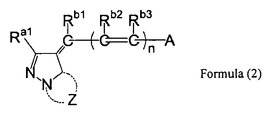
- The optical recording medium according to claim 1 or 2, wherein the dye compound is represented by Formula (3):

- The optical recording medium according to claim 3, wherein Ra4 in Formula (3) is an alkyl group or an aryl group.
- An optical recording medium comprising a visible information recording layer on a substrate, wherein the visible information recording layer is irradiated by a laser beam multiple times on substantially the same track to record visible information, and includes a dye compound represented by Formula (1):

- An optical recording medium comprising a visible information recording layer on a disk-shaped substrate, wherein the visible information recording layer is irradiated by a laser beam by oscillating the laser beam multiple times along substantially the same track in a radial direction to record visible information, and includes a dye compound represented by Formula (1):

- A method of using a dye compound represented by the following Formula (1) in an optical recording medium comprising a visible information recording layer on a disk-shaped substrate, wherein the dye compound is used as a material for the visible information recording layer which is irradiated by a laser beam by oscillating the laser beam multiple times along substantially the same track in a radial direction to record visible information:

- A visible information recording method for recording visible information at a visible information recording layer using an optical recording medium having the visible information recording layer including a dye compound represented by the following Formula (1) on a disk-shaped substrate, wherein the visible information recording layer is irradiated by a laser beam by oscillating the laser beam in a radial direction multiple times along substantially the same track:

- The optical recording medium according to claim 1, wherein Ra1 is an alkyl group having 1 to 12 carbon atoms.
- The optical recording medium according to claim 1, wherein Ra2 is an aliphatic group or an aryl group and Ra3 is a hydrogen atom or an aliphatic group.
- The optical recording medium according to claim 1, wherein Rb1, Rb2 and Rb3 each independently represent a hydrogen atom or an aliphatic group.
- The optical recording medium according to claim 1, wherein A represents an alkyl group having 1 to 15 carbon atoms in total, an aryl group having 6 to 30 carbon atoms in total, or a 5-membered to 7-membered heterocyclic ring group having 2 to 20 carbon atoms in total.
- The optical recording medium according to claim 3, wherein Ra4 represents an aliphatic group, an aryl group, or a heterocyclic ring group.
- The optical recording medium according to claim 3, wherein Ra1 is an alkyl group having 1 to 8 carbon atoms, Ra4 is an alkyl group or an aryl group, Rb1, Rb2 and Rb3 are hydrogen atoms, and n is 0 or 1.
- The optical recording medium according to claim 3, wherein A is selected from groups represented by the following (A-1) to (A-14);


- The optical recording medium according to claim 3, wherein A is an azole ring and the azole ring represented by A has the same azole skeleton structure as a pyrazoline ring to which Ra1 is bonded.
- The optical recording medium according to claim 1, wherein the optical recording medium comprises the visible information recording layer, a digital information recording layer for recording coded information, and two substrates sandwiching both the visible information recording layer and the digital information recording layer therebetween.
Applications Claiming Priority (2)
| Application Number | Priority Date | Filing Date | Title |
|---|---|---|---|
| JP2006107828A JP2007276343A (en) | 2006-04-10 | 2006-04-10 | Optical recording medium, visible information recording method, and method of using dye compound |
| PCT/JP2007/057551 WO2007119672A1 (en) | 2006-04-10 | 2007-04-04 | Optical recording medium, visible information recording method and use of dye compound |
Publications (1)
| Publication Number | Publication Date |
|---|---|
| EP2011661A1 true EP2011661A1 (en) | 2009-01-07 |
Family
ID=38609431
Family Applications (1)
| Application Number | Title | Priority Date | Filing Date |
|---|---|---|---|
| EP07740987A Withdrawn EP2011661A1 (en) | 2006-04-10 | 2007-04-04 | Optical recording medium, visible information recording method and use of dye compound |
Country Status (7)
| Country | Link |
|---|---|
| US (1) | US20090274034A1 (en) |
| EP (1) | EP2011661A1 (en) |
| JP (1) | JP2007276343A (en) |
| KR (1) | KR20090025195A (en) |
| CN (1) | CN101421115A (en) |
| TW (1) | TW200802353A (en) |
| WO (1) | WO2007119672A1 (en) |
Families Citing this family (1)
| Publication number | Priority date | Publication date | Assignee | Title |
|---|---|---|---|---|
| JP5834029B2 (en) * | 2012-03-30 | 2015-12-16 | 富士フイルム株式会社 | Pigment, pigment composition using the same, coloring composition, and color filter |
Family Cites Families (42)
| Publication number | Priority date | Publication date | Assignee | Title |
|---|---|---|---|---|
| JPS58175693A (en) | 1982-04-08 | 1983-10-14 | Ricoh Co Ltd | High-density optical information recording medium |
| JPS5955795A (en) | 1982-09-27 | 1984-03-30 | Tdk Corp | Optical recording medium |
| JPS5931194A (en) | 1982-08-17 | 1984-02-20 | 凸版印刷株式会社 | Bookbinding machine which can select collation |
| JPS6018387A (en) | 1983-07-11 | 1985-01-30 | Tdk Corp | Optical recording medium |
| JPS6019586A (en) | 1983-07-13 | 1985-01-31 | Tdk Corp | Optical recording medium |
| JPS6019587A (en) | 1983-07-13 | 1985-01-31 | Tdk Corp | Optical recording medium |
| JPS6035054A (en) | 1983-08-05 | 1985-02-22 | Tdk Corp | Optical recording medium |
| JPS6036190A (en) | 1983-08-09 | 1985-02-25 | Tdk Corp | Optical recording medium |
| JPS6036191A (en) | 1983-08-09 | 1985-02-25 | Tdk Corp | Optical recording medium |
| JPS6044554A (en) | 1983-08-20 | 1985-03-09 | Tdk Corp | Light recording medium |
| JPS6044555A (en) | 1983-08-20 | 1985-03-09 | Tdk Corp | Light recording medium |
| JPS6044390A (en) | 1983-08-23 | 1985-03-09 | Tdk Corp | Optical recording medium |
| JPS6044389A (en) | 1983-08-23 | 1985-03-09 | Tdk Corp | Optical recording medium |
| JPS6047069A (en) | 1983-08-24 | 1985-03-14 | Tdk Corp | Optical recording medium |
| JPS6054892A (en) | 1983-09-05 | 1985-03-29 | Tdk Corp | optical recording medium |
| DE3503995A1 (en) | 1984-02-06 | 1985-08-08 | Ricoh Co., Ltd., Tokio/Tokyo | OPTICAL INFORMATION RECORD CARRIER |
| JPH0626028B2 (en) | 1984-02-06 | 1994-04-06 | 株式会社リコー | Optical information recording medium |
| JPS63209995A (en) | 1987-02-27 | 1988-08-31 | Fuji Photo Film Co Ltd | Optical data recording medium |
| JP3009909B2 (en) | 1990-05-21 | 2000-02-14 | ティーディーケイ株式会社 | Optical recording medium |
| JPH0474690A (en) | 1990-07-17 | 1992-03-10 | Ricoh Co Ltd | Optical information recording medium |
| JP3451752B2 (en) | 1994-10-31 | 2003-09-29 | ソニー株式会社 | Optical recording medium |
| JP3707759B2 (en) | 1996-09-30 | 2005-10-19 | 富士写真フイルム株式会社 | Information recording medium and oxonol compound |
| JP3666702B2 (en) | 1996-10-08 | 2005-06-29 | 富士写真フイルム株式会社 | Information recording medium |
| JPH1153758A (en) | 1997-07-30 | 1999-02-26 | Mitsubishi Chem Corp | Recording / playback method |
| JP3431464B2 (en) | 1997-08-25 | 2003-07-28 | 太陽誘電株式会社 | Optical information media |
| JP3633279B2 (en) | 1998-05-27 | 2005-03-30 | 三菱化学株式会社 | Optical recording medium |
| JPH11334206A (en) | 1998-05-27 | 1999-12-07 | Mitsubishi Chemical Corp | Optical recording medium |
| JP3438587B2 (en) | 1998-05-27 | 2003-08-18 | 三菱化学株式会社 | Optical recording medium |
| JP3286249B2 (en) * | 1998-05-27 | 2002-05-27 | ティーディーケイ株式会社 | Manufacturing method of optical recording medium |
| JP3646563B2 (en) | 1998-05-27 | 2005-05-11 | 三菱化学株式会社 | Optical recording medium |
| JPH11334204A (en) | 1998-05-27 | 1999-12-07 | Mitsubishi Chemical Corp | Optical recording medium |
| JP2000057579A (en) * | 1998-08-10 | 2000-02-25 | Sony Corp | Optical disc, recording method of optical disc, and apparatus for manufacturing master disc of optical disc |
| JP2000108513A (en) | 1998-10-05 | 2000-04-18 | Mitsui Chemicals Inc | Photorecording medium |
| JP2000113516A (en) * | 1998-10-05 | 2000-04-21 | Nippon Columbia Co Ltd | Optical information recording medium |
| JP2000158818A (en) | 1998-12-01 | 2000-06-13 | Mitsui Chemicals Inc | Optical recording medium |
| JP2001342364A (en) | 2000-06-02 | 2001-12-14 | Konica Corp | Material and process for heat-sensitive transfer recording, mixture of pigment and metal ion containing compound, color toner, organic electroluminescence element, ink, optical recording medium and color filter |
| JP3846265B2 (en) | 2000-10-30 | 2006-11-15 | ヤマハ株式会社 | optical disk |
| US7268794B2 (en) * | 2000-10-30 | 2007-09-11 | Yamaha Corporation | Method of printing label on optical disk, optical disk unit, and optical disk |
| JP3956756B2 (en) | 2001-10-31 | 2007-08-08 | ヤマハ株式会社 | Optical disk recording device |
| JP2003242750A (en) | 2002-02-15 | 2003-08-29 | Yamaha Corp | Disk and thermosensitive layer member |
| JP2005219326A (en) * | 2004-02-05 | 2005-08-18 | Fuji Photo Film Co Ltd | Optical recording medium and image recording method |
| JP2006107828A (en) | 2004-10-01 | 2006-04-20 | Kawaguchi Denki Seisakusho:Kk | Slit terminal connector |
-
2006
- 2006-04-10 JP JP2006107828A patent/JP2007276343A/en not_active Withdrawn
-
2007
- 2007-04-04 EP EP07740987A patent/EP2011661A1/en not_active Withdrawn
- 2007-04-04 CN CNA2007800128183A patent/CN101421115A/en active Pending
- 2007-04-04 US US12/296,595 patent/US20090274034A1/en not_active Abandoned
- 2007-04-04 WO PCT/JP2007/057551 patent/WO2007119672A1/en not_active Ceased
- 2007-04-04 KR KR1020087026691A patent/KR20090025195A/en not_active Withdrawn
- 2007-04-09 TW TW096112284A patent/TW200802353A/en unknown
Non-Patent Citations (1)
| Title |
|---|
| See references of WO2007119672A1 * |
Also Published As
| Publication number | Publication date |
|---|---|
| WO2007119672A1 (en) | 2007-10-25 |
| CN101421115A (en) | 2009-04-29 |
| KR20090025195A (en) | 2009-03-10 |
| TW200802353A (en) | 2008-01-01 |
| US20090274034A1 (en) | 2009-11-05 |
| JP2007276343A (en) | 2007-10-25 |
Similar Documents
| Publication | Publication Date | Title |
|---|---|---|
| JP2005219326A (en) | Optical recording medium and image recording method | |
| US20090058982A1 (en) | Optical recording medium and method of recording visible information | |
| EP2011661A1 (en) | Optical recording medium, visible information recording method and use of dye compound | |
| JP4213568B2 (en) | Information recording method | |
| CN100405486C (en) | Optical information recording medium, manufacturing method thereof, and optical information recording method | |
| US20050123711A1 (en) | Optical information recording medium and information recording method | |
| EP1193699A1 (en) | Optical information recording medium and information recording method | |
| US20070237051A1 (en) | Optical Recording Medium and Recording Method | |
| US20080130475A1 (en) | Optical Disk | |
| JP2006196035A (en) | Optical disk | |
| US20080080361A1 (en) | Optical Recording Medium | |
| JP2005129108A (en) | Optical information recording medium | |
| JP2006260730A (en) | Optical disk and optical recording method | |
| JP2006196039A (en) | Optical disk | |
| JP2006155751A (en) | Optical disk | |
| JP2005174406A (en) | Optical information recording medium, optical information recording medium manufacturing method, and optical information recording method | |
| JP2006196038A (en) | Optical disk | |
| JP2006196036A (en) | Optical disk | |
| JP2005285167A (en) | Optical recording medium | |
| JP2006040440A (en) | Image recording method to optical disk | |
| JP2006228278A (en) | Optical disk | |
| JP2006031899A (en) | Optical disk | |
| JP2008146726A (en) | Optical information recording medium, substrate, stamper, mold, and method of manufacturing optical information recording medium | |
| JP2006155692A (en) | Optical disk | |
| JP2006260729A (en) | Optical disk |
Legal Events
| Date | Code | Title | Description |
|---|---|---|---|
| PUAI | Public reference made under article 153(3) epc to a published international application that has entered the european phase |
Free format text: ORIGINAL CODE: 0009012 |
|
| 17P | Request for examination filed |
Effective date: 20081106 |
|
| AK | Designated contracting states |
Kind code of ref document: A1 Designated state(s): AT BE BG CH CY CZ DE DK EE ES FI FR GB GR HU IE IS IT LI LT LU LV MC MT NL PL PT RO SE SI SK TR |
|
| AX | Request for extension of the european patent |
Extension state: AL BA HR MK RS |
|
| STAA | Information on the status of an ep patent application or granted ep patent |
Free format text: STATUS: THE APPLICATION HAS BEEN WITHDRAWN |
|
| 18W | Application withdrawn |
Effective date: 20090319 |