JP2006155751A - Optical disk - Google Patents
Optical disk Download PDFInfo
- Publication number
- JP2006155751A JP2006155751A JP2004344790A JP2004344790A JP2006155751A JP 2006155751 A JP2006155751 A JP 2006155751A JP 2004344790 A JP2004344790 A JP 2004344790A JP 2004344790 A JP2004344790 A JP 2004344790A JP 2006155751 A JP2006155751 A JP 2006155751A
- Authority
- JP
- Japan
- Prior art keywords
- layer
- recording
- range
- recording layer
- image
- Prior art date
- Legal status (The legal status is an assumption and is not a legal conclusion. Google has not performed a legal analysis and makes no representation as to the accuracy of the status listed.)
- Pending
Links
Images
Abstract
Description
本発明は、光ディスクに関し、特に、レーベル面(記録面とは反対側の面)に可視画像を記録することができる光ディスクに関する。 The present invention relates to an optical disc, and more particularly, to an optical disc capable of recording a visible image on a label surface (a surface opposite to a recording surface).
従来から、レーザー光により一回限りの情報の記録が可能な光ディスク(光ディスク)が知られている。この光ディスクは、追記型CD(所謂CD−R)とも称され、その代表的な構造は、透明な円盤状基板上に有機色素からなる記録層、金等の金属からなる光反射層、更に樹脂製の保護層がこの順に積層状態で設けられている。そしてこのCD−Rへの情報の記録は、近赤外域のレーザー光(通常は780nm付近の波長のレーザー光)をCD−Rに照射することにより行われ、記録層の照射部分がその光を吸収して局所的に温度上昇し、物理的或いは化学的変化(例えば、ピットの生成)が生じてその光学的特性を変えることにより、情報が記録される。一方、情報の読み取り(再生)もまた記録用のレーザー光と同じ波長のレーザー光を照射することにより行われ、記録層の光学的特性が変化した部位(記録部分)と変化しない部位(未記録部分)との反射率の違いを検出することにより情報が再生される。 Conventionally, an optical disc (optical disc) capable of recording information only once by laser light is known. This optical disk is also called a recordable CD (so-called CD-R), and its typical structure is a recording layer made of an organic dye on a transparent disk-shaped substrate, a light reflecting layer made of a metal such as gold, and a resin. A protective layer made of a metal is provided in this order in a laminated state. Information recording on this CD-R is performed by irradiating the CD-R with a near-infrared laser beam (usually a laser beam having a wavelength near 780 nm), and the irradiated portion of the recording layer emits the light. Information is recorded by absorbing and locally raising the temperature, causing a physical or chemical change (eg, pit generation) and changing its optical properties. On the other hand, reading (reproduction) of information is also performed by irradiating a laser beam having the same wavelength as that of the recording laser beam. Information is reproduced by detecting the difference in reflectance from (part).
近年、記録密度のより高い光ディスクが求められている。このような要望に対して、追記型デジタル・ヴァサタイル・ディスク(所謂DVD−R)と称される光ディスクが提案されている。このDVD−Rは、照射されるレーザー光のトラッキングのための案内溝(プレグルーブ)がCD−Rに比べて半分以下(0.74〜0.8μm)と狭く形成された透明な円盤状基板上に、色素からなる記録層、そして通常は該記録層の上に光反射層、そして更に必要により保護層を設けてなるディスクを二枚、或いは該ディスクと同じ形状の円盤状保護基板とを該記録層を内側にして接着剤で貼り合わせた構造を有している。DVD−Rへの情報の記録再生は、可視レーザー光(通常は、630nm〜680nmの範囲の波長のレーザー光)を照射することにより行われ、CD−Rより高密度の記録が可能であるとされている。 In recent years, optical discs with higher recording density have been demanded. In response to such a demand, an optical disk called a recordable digital vasatile disk (so-called DVD-R) has been proposed. This DVD-R is a transparent disk-shaped substrate in which the guide groove (pre-groove) for tracking the irradiated laser beam is narrower than half of the CD-R (0.74-0.8 μm). On top of that, a recording layer made of a dye, and usually two light reflecting layers on the recording layer, and further a protective layer provided if necessary, or a disk-shaped protective substrate having the same shape as the disk The recording layer has a structure in which the recording layer is bonded inside with an adhesive. Information recording / reproduction on a DVD-R is performed by irradiating visible laser light (usually laser light having a wavelength in the range of 630 nm to 680 nm), and recording at a higher density than CD-R is possible. Has been.
ところで、前記の種々の光ディスクとしては、音楽データ等が記録される記録面とは反対側の面(レーベル面)に、記録面に記録した音楽データの楽曲タイトルや、記録したデータを識別するためのタイトル等の可視情報を印刷したラベルを貼付したものが知られている。このような光ディスクは、プリンター等によって円形のラベルシート上にタイトル等を予め印刷し、当該ラベルシートを光ディスクのレーベル面に貼付することにより作製される。 By the way, in the various optical discs described above, the music title of the music data recorded on the recording surface and the recorded data are identified on the surface (label surface) opposite to the recording surface on which the music data is recorded. There is known a label on which visible information such as a title is attached. Such an optical disc is produced by printing a title or the like on a circular label sheet in advance by a printer or the like and sticking the label sheet on the label surface of the optical disc.
上述のようにタイトル等の所望の可視画像をレーベル面に記録した光ディスクを作製する場合には、光ディスクドライブとは別にプリンターが必要となる。従って、光ディスクドライブを用いて、ある光ディスクの記録面に記録を行った後、該光ディスクを光ディスクドライブから取り出して、上記のように別に用意したプリンターによって印刷されたラベルシートを貼付するなどといった煩雑な作業を行う必要がある。また、ラベルシートを貼付する方法では、接着剤等の耐久性の問題から使用中に剥離したり、張り合わせの際の芯ズレから光ディスクの回転時のアンバランスが大きくなり、その結果、記録、再生が不可能となることもある。 As described above, when an optical disc in which a desired visible image such as a title is recorded on the label surface is manufactured, a printer is required separately from the optical disc drive. Therefore, after recording on a recording surface of an optical disk using an optical disk drive, the optical disk is taken out from the optical disk drive, and a label sheet printed by a separately prepared printer as described above is attached. Need to do work. In addition, the method of applying a label sheet peels off during use due to durability problems such as adhesives, and the unbalance during rotation of the optical disk increases due to misalignment during lamination, resulting in recording and playback. May not be possible.
そこで、レーザー光で可視情報を記録可能な可視画像形成層を有する記録媒体が提案されている(例えば、特許文献1、2参照。)。この記録媒体は、プリンター等を別途用意することなく、光ディスクドライブによって光ディスクのレーベル面に所望の画像記録を行うことができる。しかしながら、このような光ディスクには、可視画像形成層表面に、樹脂層が隣接して設けられているが、その樹脂層に映り込みが生じ、形成された可視画像の視認性が低下してしまうことが問題となっていた。
本発明は、以上の従来の問題点に鑑みなされたものであり、以下の目的を達成することを課題とする。即ち、
本発明の目的は、レーベル面側にある画像記録層(可視画像形成層)に対し、レーザー光を使用して視認性の高い可視画像を記録可能な光ディスクを提供することにある。
This invention is made | formed in view of the above conventional trouble, and makes it a subject to achieve the following objectives. That is,
An object of the present invention is to provide an optical disc capable of recording a visible image with high visibility using a laser beam on an image recording layer (visible image forming layer) on the label surface side.
前記課題を解決する手段は以下の通りである。即ち、
本発明の光ディスクは、レーベル面側に、レーザー光の照射により可視画像が記録される画像記録層と、屈折率が1.4〜1.6である樹脂層と、屈折率が1.2〜1.4であると共に、最表面層となる反射防止層と、をこの順に有してなることを特徴とする。
また、前記樹脂層と、前記反射防止層と、の間にプライマー層を有してなることが好ましい態様である。
Means for solving the problems are as follows. That is,
The optical disc of the present invention has, on the label surface side, an image recording layer on which a visible image is recorded by laser light irradiation, a resin layer having a refractive index of 1.4 to 1.6, and a refractive index of 1.2 to 1.4 and an antireflection layer which is the outermost surface layer in this order.
Moreover, it is a preferable aspect that a primer layer is provided between the resin layer and the antireflection layer.
本発明によれば、レーベル面側にある画像記録層に対し、レーザー光を使用して視認性の高い可視画像を記録可能な光ディスクを提供することができる。 ADVANTAGE OF THE INVENTION According to this invention, the optical disk which can record a visible image with high visibility using a laser beam with respect to the image recording layer in the label surface side can be provided.
以下、本発明の光ディスクについて説明する。
本発明の光ディスクは、レーベル面側に、レーザー光の照射により可視画像が記録される画像記録層と、屈折率が1.4〜1.6である樹脂層と、屈折率が1.2〜1.4であると共に、最表面層となる反射防止層と、をこの順に有してなることを特徴とする。
The optical disk of the present invention will be described below.
The optical disc of the present invention has, on the label surface side, an image recording layer on which a visible image is recorded by laser light irradiation, a resin layer having a refractive index of 1.4 to 1.6, and a refractive index of 1.2 to 1.4 and an antireflection layer which is the outermost surface layer in this order.
本発明の光ディスクの種類としては、読出し専用型、追記型、書換え可能型等のいずれでもよいが、追記型であることが好ましい。また、情報の記録形式としては、相変化型、光磁気型、色素型等、特に制限されないが、色素型であることが好ましい。 The type of the optical disk of the present invention may be any of a read-only type, a write-once type, a rewritable type, etc., but is preferably a write-once type. The information recording format is not particularly limited, such as a phase change type, a magneto-optical type, and a dye type, but is preferably a dye type.
本発明の光ディスクの層構成としては、例えば、以下の構成が挙げられる。なお、下記の構成例におけるダミー基板は、本発明における樹脂層に相当する。
(1)基板上に、記録層、反射層、保護層を順次形成し、該保護層上に画像記録層、ダミー基板、及び(プライマー層を介して)反射防止層を順次設ける構成である。
(2)基板上に、記録層、反射層、接着層を順次形成し、該接着層上に画像記録層、ダミー基板、及び(プライマー層を介して)反射防止層を順次設ける構成である。
(3)基板上に、記録層、反射層、保護層、接着層を順次形成し、該接着層上に画像記録層、ダミー基板、及び(プライマー層を介して)反射防止層を順次設ける構成である。
(4)基板上に、記録層、反射層、保護層、接着層、保護層を順次形成し、該保護層上に画像記録層、ダミー基板、及び(プライマー層を介して)反射防止層を順次設ける構成である。
(5)基板上に、記録層、反射層、保護層、接着層、保護層、反射層を順次形成し、該反射層上に画像記録層、ダミー基板、及び(プライマー層を介して)反射防止層を順次設ける構成である。
(6)基板上に、記録層、反射層、接着層、反射層を順次形成し、該反射層上に画像記録層、ダミー基板、及び(プライマー層を介して)反射防止層を順次設ける構成である。
なお、上記(1)〜(6)の層構成は単なる例示であり、当該層構成は上述の順番のみでなく、一部を入れ替えてもよいし、また、一部を省略してもかまわない。例えば、更に、各層は1層で構成されても複数層で構成されてもよい。
以下、各構成要素について説明する。
Examples of the layer configuration of the optical disc of the present invention include the following configurations. The dummy substrate in the following configuration example corresponds to the resin layer in the present invention.
(1) The recording layer, the reflective layer, and the protective layer are sequentially formed on the substrate, and the image recording layer, the dummy substrate, and the antireflection layer (via the primer layer) are sequentially provided on the protective layer.
(2) The recording layer, the reflective layer, and the adhesive layer are sequentially formed on the substrate, and the image recording layer, the dummy substrate, and the antireflection layer (via the primer layer) are sequentially provided on the adhesive layer.
(3) A configuration in which a recording layer, a reflective layer, a protective layer, and an adhesive layer are sequentially formed on a substrate, and an image recording layer, a dummy substrate, and an antireflection layer (via a primer layer) are sequentially provided on the adhesive layer. It is.
(4) A recording layer, a reflective layer, a protective layer, an adhesive layer, and a protective layer are sequentially formed on the substrate, and an image recording layer, a dummy substrate, and an antireflection layer (via a primer layer) are formed on the protective layer. It is the structure provided sequentially.
(5) A recording layer, a reflective layer, a protective layer, an adhesive layer, a protective layer, and a reflective layer are sequentially formed on the substrate, and an image recording layer, a dummy substrate, and a reflection (through a primer layer) are formed on the reflective layer. In this configuration, the prevention layer is sequentially provided.
(6) A configuration in which a recording layer, a reflective layer, an adhesive layer, and a reflective layer are sequentially formed on a substrate, and an image recording layer, a dummy substrate, and an antireflection layer (via a primer layer) are sequentially provided on the reflective layer. It is.
The layer configurations of (1) to (6) are merely examples, and the layer configuration is not limited to the order described above, and a part of the layer configuration may be replaced or a part of the layer configuration may be omitted. . For example, each layer may be composed of one layer or a plurality of layers.
Hereinafter, each component will be described.
まず、本発明の光ディスクにおいてレーベル面側に形成される、画像記録層、樹脂層、及び反射防止層について説明する。
なお、樹脂層及び反射防止層における屈折率とは、人間の視感度の高い領域である波長500〜600nmの光に対する屈折率である。
また、各層の屈折率の測定方法としては、アッベ屈折計によるもの、光吸収スペクトルからクラマース・クローニッヒの関係式を用いて求めるものなどが挙げられるが、光ディスクについては、その構造上、特に、多入射角分光エリプソメトリーなどを用いることがで好ましい。
First, the image recording layer, the resin layer, and the antireflection layer formed on the label surface side in the optical disk of the present invention will be described.
The refractive index in the resin layer and the antireflection layer is a refractive index with respect to light having a wavelength of 500 to 600 nm, which is a region having high human visibility.
In addition, examples of the method for measuring the refractive index of each layer include an Abbe refractometer and a method using a Kramers-Kronig relational expression from an optical absorption spectrum. It is preferable to use incident angle spectroscopic ellipsometry or the like.
[画像記録層]
本発明の光ディスクは、前述のように、レーベル面側に、画像記録層を有する。
画像記録層には、レーザー光により、文字、図形、絵柄など、ユーザーが所望する可視画像(可視情報)が記録される。可視画像としては、例えば、ディスクのタイトル、内容情報、内容のサムネール、関連した絵柄、デザイン的な絵柄、著作権情報、記録日時、記録方法、記録フォーマット等が挙げられる。
[Image recording layer]
As described above, the optical disc of the present invention has an image recording layer on the label surface side.
Visible images (visible information) desired by the user, such as characters, graphics, and patterns, are recorded on the image recording layer by laser light. Examples of visible images include disc titles, content information, content thumbnails, related patterns, design patterns, copyright information, recording date, recording method, recording format, and the like.
ここで、画像記録層に記録される可視画像とは、視覚的に認識可能な画像を意味し、文字(列)、絵柄、図形などあらゆる視認可能な情報を含む。また、文字情報としては、使用可能者指定情報、使用期間指定情報、使用可能回数指定情報、レンタル情報、分解能指定情報、レイヤー指定情報、ユーザ指定情報、著作権者情報、著作権番号情報、製造者情報、製造日情報、販売日情報、販売店又は販売者情報、使用セット番号情報、地域指定情報、言語指定情報、用途指定情報、製品使用者情報、使用番号情報等が挙げられる。 Here, the visible image recorded in the image recording layer means a visually recognizable image, and includes all visually recognizable information such as characters (columns), designs, and figures. Also, as character information, usable person designation information, use period designation information, usable number designation information, rental information, resolution designation information, layer designation information, user designation information, copyright holder information, copyright number information, manufacturing Information, manufacturer date information, sale date information, dealer or seller information, use set number information, region designation information, language designation information, application designation information, product user information, use number information, and the like.
画像記録層は、レーザー光の照射により、文字、画像、絵柄などの画像情報を視認可能に記録できればよく、その構成材料としては、後述の記録層において説明する記録物質(色素や相変化記録材料)を好適に用いることができる。 The image recording layer only needs to be able to record image information such as characters, images, and patterns by laser irradiation so that the recording material is a recording material (pigment or phase change recording material) described later in the recording layer. ) Can be suitably used.
また、本発明の光ディスクにおいては、後述する記録層の構成成分(記録物質:色素又は相変化記録材料)と画像記録層の構成成分とを同じとしても異ならせてもよいが、記録層と画像記録層とでそれぞれ要求される特性が相違するため、構成成分は異ならせることが好ましい。具体的には、記録層の構成成分は、記録・再生特性に優れるものとし、画像記録層の構成成分は、記録される可視画像のコントラストが高くなるものとすることが好ましい。
特に、画像記録層の構成成分として色素を用いる場合には、画像記録層の屈折率と記録画像のコントラスト向上との観点から、後述する色素の中でも特に、シアニン色素、フタロシアニン色素、アゾ色素、アゾ金属錯体、オキソノール色素を用いることが好ましい。
また、記録層と画像記録層のうちのいずれか一方が相変化型で、他方が色素型としてもよい。この場合、記録層が相変化型で、画像記録層が色素型であることが好ましい。
In the optical disc of the present invention, the constituent components of the recording layer (recording substance: dye or phase change recording material) to be described later and the constituent components of the image recording layer may be the same or different. Since the required characteristics differ between the recording layers, it is preferable that the constituent components are different. Specifically, the constituent components of the recording layer are preferably excellent in recording / reproducing characteristics, and the constituent components of the image recording layer are preferably those in which the contrast of the recorded visible image is high.
In particular, when a dye is used as a component of the image recording layer, a cyanine dye, a phthalocyanine dye, an azo dye, an azo dye, among the dyes described later, are particularly preferred from the viewpoint of improving the refractive index of the image recording layer and the contrast of the recorded image. It is preferable to use a metal complex or an oxonol dye.
Further, one of the recording layer and the image recording layer may be a phase change type and the other may be a dye type. In this case, the recording layer is preferably a phase change type and the image recording layer is preferably a dye type.
画像記録層は、後述の色素を溶剤に溶解して塗布液を調製し、該塗布液を樹脂層上に塗布することによって形成することができる。溶剤としては後述する記録層の塗布液の調製に使用する溶剤と同じ溶剤を使用することができる。その他の添加剤、塗布方法など、後述の記録層と同様にして行うことができる。 The image recording layer can be formed by preparing a coating solution by dissolving a dye described later in a solvent and coating the coating solution on the resin layer. As the solvent, the same solvents as those used for preparing the recording layer coating liquid described later can be used. Other additives and coating methods can be carried out in the same manner as the recording layer described later.
画像記録層の層厚としては、0.01〜200μmとすることが好ましく、0.05〜100μmとすることがより好ましく、0.1〜50μmとすることが更に好ましい。 The thickness of the image recording layer is preferably 0.01 to 200 μm, more preferably 0.05 to 100 μm, and still more preferably 0.1 to 50 μm.
本発明の光ディスクにおいては、画像記録層にトラッキング用の溝を設けてもよい。上述の層構成例においては、画像記録層は、ダミー基板(樹脂層)に隣接して形成されるから、ダミー基板に所望の溝を設けることにより、画像記録層に容易に溝を設けることができる。このようにトラッキング用の溝が形成された画像記録層を有することから、本発明の光ディスクは、溝でレーザーピックアップをトラッキングした状態で画像記録を行うことができ、ピックアップを精密に位置制御することができるため、緻密な画像を記録することができる。また、画像記録層に溝を設けることにより、光が干渉して表面がきれいな虹色に見える効果もある。 In the optical disk of the present invention, a tracking groove may be provided in the image recording layer. In the above layer configuration example, the image recording layer is formed adjacent to the dummy substrate (resin layer). Therefore, by providing a desired groove in the dummy substrate, the image recording layer can be easily provided with a groove. it can. Since it has an image recording layer in which a tracking groove is formed in this way, the optical disc of the present invention can perform image recording in a state where the laser pickup is tracked by the groove, and precisely controls the position of the pickup. Therefore, a precise image can be recorded. Further, by providing grooves in the image recording layer, there is an effect that light interferes and the surface looks like a beautiful rainbow color.
[樹脂層(ダミー基板)]
本発明における樹脂層は、記述の層構成例においては、ダミー基板とも呼ばれ、屈折率が1.4〜1.6となるものであれば、後述の基板と同じ樹脂材料を使用することができる。
また、本発明の樹脂層は、層構成に応じて、上記の画像記録層を保護するための層として設けられることもある。
[Resin layer (dummy substrate)]
The resin layer in the present invention is also referred to as a dummy substrate in the described layer configuration example, and if the refractive index is 1.4 to 1.6, the same resin material as that of the substrate described later can be used. it can.
The resin layer of the present invention may be provided as a layer for protecting the image recording layer according to the layer structure.
また、樹脂層の厚さは、光ディスクの層構成に応じて決定すればよく、一般的には、0.05〜1.1mmとすることが好ましく、0.1〜0.7mmとすることがより好ましい。
本発明における樹脂層にはグルーブが形成されていてもよい。このグルーブの存在により、上述のように、結果的に、画像記録層にトラッキング用の溝(グルーブ)を設けることができる。
この際、樹脂層(ダミー基板)に形成されるグルーブのトラックピッチは、0.25〜2.0nmの範囲にとすることが好ましく、0.3〜1.6nmの範囲とすることがより好ましい。
また、グルーブの深さ(溝深さ)は、20〜300nmの範囲とすることが好ましく、30〜200nmの範囲とすることがより好ましい。
更に、グルーブの溝幅は、80〜1000nmの範囲とすることが好ましく、100〜500nmの範囲とすることがより好ましい。
グルーブの溝傾斜角度は、20〜80°の範囲とすることが好ましく、30〜70°の範囲とすることがより好ましい。
The thickness of the resin layer may be determined according to the layer structure of the optical disk, and is generally preferably 0.05 to 1.1 mm, and preferably 0.1 to 0.7 mm. More preferred.
A groove may be formed in the resin layer in the present invention. Due to the presence of the groove, as described above, a tracking groove can be provided in the image recording layer.
At this time, the track pitch of the grooves formed on the resin layer (dummy substrate) is preferably in the range of 0.25 to 2.0 nm, and more preferably in the range of 0.3 to 1.6 nm. .
Moreover, it is preferable to make the depth (groove depth) of a groove into the range of 20-300 nm, and it is more preferable to set it as the range of 30-200 nm.
Furthermore, the groove width of the groove is preferably in the range of 80 to 1000 nm, and more preferably in the range of 100 to 500 nm.
The groove inclination angle of the groove is preferably in the range of 20 to 80 °, and more preferably in the range of 30 to 70 °.
[反射防止層]
本発明における反射防止層は、上記樹脂層(ダミー層)の表面に形成される層であって、屈折率が1.2〜1.4であると共に、最表面層となる。
このように、画像記録層上に形成される樹脂層と同等若しくは小さな屈折率の反射防止層を当該樹脂層上に設けることで、この樹脂層への映り込みを防止することでき、コントラストの優れた可視画像を得ることができる。
[Antireflection layer]
The antireflection layer in the present invention is a layer formed on the surface of the resin layer (dummy layer) and has a refractive index of 1.2 to 1.4 and is the outermost surface layer.
In this way, by providing an antireflection layer having a refractive index equal to or smaller than that of the resin layer formed on the image recording layer on the resin layer, reflection on the resin layer can be prevented, and the contrast is excellent. A visible image can be obtained.
反射防止層を構成する材料としては、形成された層の屈折率が上記の範囲に入るようなものであれば制限無く用いることができるが、具体的には、フッ化マグネシウム、フッ化カルシウム、フルオロシリコーン、ポリフルオロテトラエチレン等が挙げられる。
また、フッ素含有樹脂を用いる場合には、樹脂自体に溶媒への溶解性等の特性を付与するために、官能基を導入することができる。このような官能基としては、カルボキシル基、ヒドロキシル基、スルホ基などがある。
As a material constituting the antireflection layer, any material can be used without limitation as long as the refractive index of the formed layer falls within the above range. Specifically, magnesium fluoride, calcium fluoride, Examples include fluorosilicone and polyfluorotetraethylene.
When a fluorine-containing resin is used, a functional group can be introduced in order to impart properties such as solubility in a solvent to the resin itself. Examples of such a functional group include a carboxyl group, a hydroxyl group, and a sulfo group.
これらのフッ素含有化合物からなる層は、隣接する樹脂層との密着力が低いため、反射防止層及び樹脂層の両方に対して密着性の高いプライマー層を、反射防止層と樹脂層との間に介在させることにより、両層の密着性及び接着性を高めることができる。 Since the layer made of these fluorine-containing compounds has low adhesion to the adjacent resin layer, a primer layer having high adhesion to both the antireflection layer and the resin layer is provided between the antireflection layer and the resin layer. By interposing in, adhesion and adhesiveness of both layers can be improved.
ここで、反射防止層及び樹脂層の両方に対して高い密着性を有するプライマー層としては、粘着性を有する各種ポリマーのほか、架橋剤として寄与するような、エポキシ基、イソシアネート基、アルコキシシリル基等の官能を有するオリゴマーなども用いることができる。
なお、このプライマー層は、反射防止層の機能を低下させない範囲の厚さで設けられることが好ましい。
Here, as a primer layer having high adhesion to both the antireflection layer and the resin layer, in addition to various polymers having adhesiveness, an epoxy group, an isocyanate group, an alkoxysilyl group that contributes as a crosslinking agent An oligomer having a function such as can also be used.
In addition, it is preferable that this primer layer is provided with the thickness of the range which does not reduce the function of an antireflection layer.
反射防止層の厚さは、反射防止層としての機能の発現性、摩擦などに対する耐久性、及び反りなどの変形防止の観点から、0.1〜100μmの範囲であることが好ましく、0.5〜50μmの範囲であることがより好ましく、1〜30μmの範囲であることが更に好ましい。 The thickness of the antireflection layer is preferably in the range of 0.1 to 100 μm from the viewpoint of the development of functions as the antireflection layer, durability against friction, and deformation prevention such as warpage. More preferably, it is in the range of ˜50 μm, and further preferably in the range of 1-30 μm.
[基板]
本発明の光ディスクの基板は、従来の光ディスクの基板として用いられている各種の材料から任意に選択することができる。
基板材料としては、例えば、ガラス、ポリカーボネート、ポリメチルメタクリレート等のアクリル樹脂、ポリ塩化ビニル、塩化ビニル共重合体等の塩化ビニル系樹脂、エポキシ樹脂、アモルファスポリオレフィン及びポリエステルなどを挙げることができ、所望によりそれらを併用してもよい。
なお、これらの材料はフィルム状として又は剛性のある基板として使うことができる。上記材料の中では、耐湿性、寸法安定性及び価格などの点からポリカーボネートが好ましい。
[substrate]
The substrate of the optical disk of the present invention can be arbitrarily selected from various materials used as a substrate of a conventional optical disk.
Examples of substrate materials include acrylic resins such as glass, polycarbonate, and polymethyl methacrylate, vinyl chloride resins such as polyvinyl chloride and vinyl chloride copolymers, epoxy resins, amorphous polyolefins, and polyesters. You may use them together.
These materials can be used as a film or as a rigid substrate. Among the above materials, polycarbonate is preferable from the viewpoint of moisture resistance, dimensional stability, price, and the like.
基板の厚さは、光ディスクの層構成に応じて決定すればよく、一般的には、0.1〜1.2mmとすることが好ましく、0.2〜1.1mmとすることがより好ましい。 The thickness of the substrate may be determined according to the layer structure of the optical disc, and is generally preferably 0.1 to 1.2 mm, and more preferably 0.2 to 1.1 mm.
基板には、トラッキング用の案内溝又はアドレス信号等の情報を表わす凹凸(グルーブ)が形成されている。
本発明の光ディスクがCD−RやCD−RWの構成の場合、グルーブのトラックピッチは、1.2〜2.0μmの範囲とすること好ましく、1.4〜1.8μmの範囲とすることがより好ましく、1.55〜1.65μmの範囲とすることが更に好ましい。
グルーブの深さ(溝深さ)は、100〜250nmの範囲とすることが好ましく、150〜230nmの範囲とすることがより好ましく、170〜210nmの範囲とすることが更に好ましい。
グルーブの半値幅は、400〜650nmの範囲とすることが好ましく、480〜600nmの範囲とすることがより好ましく、500〜580nmの範囲とすることが更に好ましい。
The substrate is provided with unevenness (grooves) representing information such as tracking guide grooves or address signals.
When the optical disk of the present invention has a CD-R or CD-RW configuration, the groove track pitch is preferably in the range of 1.2 to 2.0 μm, and preferably in the range of 1.4 to 1.8 μm. More preferably, the range of 1.55 to 1.65 μm is even more preferable.
The groove depth (groove depth) is preferably in the range of 100 to 250 nm, more preferably in the range of 150 to 230 nm, and still more preferably in the range of 170 to 210 nm.
The half width of the groove is preferably in the range of 400 to 650 nm, more preferably in the range of 480 to 600 nm, and still more preferably in the range of 500 to 580 nm.
本発明の光ディスクがDVD−R又はDVD−RWの構成の場合は、グルーブのトラックピッチは、300〜900nmの範囲とすること好ましく、350〜850nmの範囲とすることがより好ましく、400〜800nmの範囲とすることが更に好ましい。
また、グルーブの深さ(溝深さ)は、100〜160nmの範囲とすることが好ましく、120〜150nmの範囲とすることがより好ましく、130〜140nmの範囲とすることが更に好ましい。
更に、グルーブの溝幅(半値幅)は、200〜400nmの範囲とすることが好ましく、230〜380nmの範囲とすることがより好ましく、250〜350nmの範囲とすることが更に好ましい。
When the optical disc of the present invention has a DVD-R or DVD-RW configuration, the groove track pitch is preferably in the range of 300 to 900 nm, more preferably in the range of 350 to 850 nm, and more preferably in the range of 400 to 800 nm. More preferably, it is within the range.
The groove depth (groove depth) is preferably in the range of 100 to 160 nm, more preferably in the range of 120 to 150 nm, and still more preferably in the range of 130 to 140 nm.
Further, the groove width (half width) of the groove is preferably in the range of 200 to 400 nm, more preferably in the range of 230 to 380 nm, and still more preferably in the range of 250 to 350 nm.
より高い記録密度を達成するために、従来のCD−RやDVD−Rに比べて、より狭いトラックピッチのグルーブが形成された基板を用いてもよい。
この場合、グルーブのトラックピッチは、200〜400nmの範囲にとすることが好ましく、250〜350nmの範囲とすることがより好ましい。
また、グルーブの深さ(溝深さ)は、20〜150nmの範囲とすることが好ましく、50〜100nmの範囲とすることがより好ましい。
更に、グルーブの溝幅(半値幅)は、50〜250nmの範囲とすることが好ましく、100〜200nmの範囲とすることがより好ましい。
加えて、グルーブの溝傾斜角度は、20〜80°の範囲とすることが好ましく、30〜70°の範囲とすることがより好ましい。
In order to achieve a higher recording density, a substrate on which a groove having a narrower track pitch than that of a conventional CD-R or DVD-R may be used.
In this case, the groove track pitch is preferably in the range of 200 to 400 nm, and more preferably in the range of 250 to 350 nm.
Further, the depth of the groove (groove depth) is preferably in the range of 20 to 150 nm, and more preferably in the range of 50 to 100 nm.
Furthermore, the groove width (half width) of the groove is preferably in the range of 50 to 250 nm, and more preferably in the range of 100 to 200 nm.
In addition, the groove inclination angle of the groove is preferably in the range of 20 to 80 °, and more preferably in the range of 30 to 70 °.
更に、記録層が設けられる側の基板表面(グルーブが形成された面側)には、平面性の改善、接着力の向上及び記録層の変質防止の目的で、下塗層が設けられてもよい。
下塗層の材料としては、例えば、ポリメチルメタクリレート、アクリル酸・メタクリル酸共重合体、スチレン・無水マレイン酸共重合体、ポリビニルアルコール、N−メチロールアクリルアミド、スチレン・ビニルトルエン共重合体、クロルスルホン化ポリエチレン、ニトロセルロース、ポリ塩化ビニル、塩素化ポリオレフィン、ポリエステル、ポリイミド、酢酸ビニル・塩化ビニル共重合体、エチレン・酢酸ビニル共重合体、ポリエチレン、ポリプロピレン、ポリカーボネート等の高分子物質;及びシランカップリング剤などの表面改質剤などを挙げることができる。下塗層は、上記物質を適当な溶剤に溶解又は分散して塗布液を調製した後、この塗布液をスピンコート、ディップコート、エクストルージョンコートなどの塗布法により基板表面に塗布することにより形成することができる。
下塗層の層厚は一般に0.005〜20μmの範囲にあり、好ましくは0.01〜10μmの範囲である。
Furthermore, an undercoat layer may be provided on the substrate surface on the side on which the recording layer is provided (the side on which the groove is formed) for the purpose of improving flatness, improving adhesive force, and preventing alteration of the recording layer. Good.
Examples of the material for the undercoat layer include polymethyl methacrylate, acrylic acid / methacrylic acid copolymer, styrene / maleic anhydride copolymer, polyvinyl alcohol, N-methylol acrylamide, styrene / vinyl toluene copolymer, chlorosulfone. Polymer materials such as chlorinated polyethylene, nitrocellulose, polyvinyl chloride, chlorinated polyolefin, polyester, polyimide, vinyl acetate / vinyl chloride copolymer, ethylene / vinyl acetate copolymer, polyethylene, polypropylene, polycarbonate; and silane coupling And a surface modifier such as an agent. The undercoat layer is formed by dissolving or dispersing the above substances in a suitable solvent to prepare a coating solution, and then applying this coating solution to the substrate surface by a coating method such as spin coating, dip coating, or extrusion coating. can do.
The thickness of the undercoat layer is generally in the range of 0.005 to 20 μm, preferably in the range of 0.01 to 10 μm.
[記録層]
記録層は、デジタル情報などの符号情報(コード化情報)が記録される層であり、色素型、追記型、相変化型、光磁気型等が挙げられ、特に制限はないが、色素型であることが好ましい。
[Recording layer]
The recording layer is a layer on which code information (encoded information) such as digital information is recorded, and examples thereof include a dye type, a write-once type, a phase change type, and a magneto-optical type. Preferably there is.
色素型の記録層に含有される色素の具体例としては、シアニン色素、オキソノール色素、金属錯体系色素、アゾ色素、フタロシアニン色素等が挙げられる。
また、特開平4−74690号公報、特開平8−127174号公報、同11−53758号公報、同11−334204号公報、同11−334205号公報、同11−334206号公報、同11−334207号公報、特開2000−43423号公報、同2000−108513号公報、及び同2000−158818号公報等に記載されている色素が好適に用いられる。
更に、記録物質としては、トリアゾール化合物、トリアジン化合物、シアニン化合物、メロシアニン化合物、アミノブタジエン化合物、フタロシアニン化合物、桂皮酸化合物、ビオロゲン化合物、アゾ化合物、オキソノールベンゾオキサゾール化合物、ベンゾトリアゾール化合物等の有機化合物も好適に用いられる。これらの化合物の中では、シアニン化合物、アミノブタジエン化合物、ベンゾトリアゾール化合物、フタロシアニン化合物が特に好ましい。
Specific examples of the dye contained in the dye-type recording layer include a cyanine dye, an oxonol dye, a metal complex dye, an azo dye, and a phthalocyanine dye.
JP-A-4-74690, JP-A-8-127174, 11-53758, 11-334204, 11-334205, 11-334206, 11-334207 No. 2000, 43423, 2000-108513, 2000-158818, and the like are preferably used.
Further, as recording materials, organic compounds such as triazole compounds, triazine compounds, cyanine compounds, merocyanine compounds, aminobutadiene compounds, phthalocyanine compounds, cinnamic acid compounds, viologen compounds, azo compounds, oxonol benzoxazole compounds, and benzotriazole compounds are also included. Preferably used. Among these compounds, cyanine compounds, aminobutadiene compounds, benzotriazole compounds, and phthalocyanine compounds are particularly preferable.
記録層の形成は、蒸着、スパッタリング、CVD、又は溶剤塗布等の方法によって行うことができるが、溶剤塗布が好ましい。
溶剤塗布を用いた場合、記録層は、色素等の記録物質を、クエンチャー、結合剤などと共に溶剤に溶解して塗布液を調製し、次いで、この塗布液を基板上に塗布して塗膜を形成した後、乾燥することにより形成される。塗布液中の記録物質の濃度は、一般に0.01〜15質量%の範囲であり、好ましくは0.1〜10質量%の範囲、より好ましくは0.5〜5質量%の範囲、最も好ましくは0.5〜3質量%の範囲である。
The recording layer can be formed by a method such as vapor deposition, sputtering, CVD, or solvent coating, but solvent coating is preferred.
When solvent coating is used, the recording layer is prepared by dissolving a recording substance such as a dye in a solvent together with a quencher, a binder and the like to prepare a coating solution. After forming, it is formed by drying. The concentration of the recording substance in the coating solution is generally in the range of 0.01 to 15% by mass, preferably in the range of 0.1 to 10% by mass, more preferably in the range of 0.5 to 5% by mass, and most preferably. Is in the range of 0.5-3 mass%.
塗布液の溶剤としては、酢酸ブチル、乳酸エチル、セロソルブアセテートなどのエステル;メチルエチルケトン、シクロヘキサノン、メチルイソブチルケトンなどのケトン;ジクロルメタン、1,2−ジクロルエタン、クロロホルムなどの塩素化炭化水素;ジメチルホルムアミドなどのアミド;メチルシクロヘキサンなどの炭化水素;ジブチルエーテル、ジエチルエーテル、テトラヒドロフラン、ジオキサンなどのエーテル;エタノール、n−プロパノール、イソプロパノール、n−ブタノール、ジアセトンアルコールなどのアルコール;2,2,3,3−テトラフルオロプロパノールなどのフッ素系溶剤;エチレングリコールモノメチルエーテル、エチレングリコールモノエチルエーテル、プロピレングリコールモノメチルエーテルなどのグリコールエーテル類などを挙げることができる。
上記溶剤は使用する色素の溶解性を考慮して単独で、或いは二種以上を組み合わせて使用することができる。塗布液中には更に酸化防止剤、UV吸収剤、可塑剤、潤滑剤など各種の添加剤を目的に応じて添加してもよい。
Examples of the solvent of the coating solution include esters such as butyl acetate, ethyl lactate and cellosolve acetate; ketones such as methyl ethyl ketone, cyclohexanone and methyl isobutyl ketone; chlorinated hydrocarbons such as dichloromethane, 1,2-dichloroethane and chloroform; dimethylformamide and the like Amides; Hydrocarbons such as methylcyclohexane; Ethers such as dibutyl ether, diethyl ether, tetrahydrofuran, dioxane; Alcohols such as ethanol, n-propanol, isopropanol, n-butanol, diacetone alcohol; 2,2,3,3-tetra Fluorinated solvents such as fluoropropanol; ethylene glycol monomethyl ether, ethylene glycol monoethyl ether, propylene glycol monomethyl ether, etc. And the like can be mentioned recall ethers.
The said solvent can be used individually or in combination of 2 or more types in consideration of the solubility of the pigment | dye to be used. Various additives such as an antioxidant, a UV absorber, a plasticizer, and a lubricant may be further added to the coating solution depending on the purpose.
結合剤を使用する場合、その例としては、ゼラチン、セルロース誘導体、デキストラン、ロジン、ゴムなどの天然有機高分子物質;及びポリエチレン、ポリプロピレン、ポリスチレン、ポリイソブチレン等の炭化水素系樹脂;ポリ塩化ビニル、ポリ塩化ビニリデン、ポリ塩化ビニル・ポリ酢酸ビニル共重合体等のビニル系樹脂;ポリアクリル酸メチル、ポリメタクリル酸メチル等のアクリル樹脂;ポリビニルアルコール、塩素化ポリエチレン、エポキシ樹脂、ブチラール樹脂、ゴム誘導体、フェノール・ホルムアルデヒド樹脂等の熱硬化性樹脂の初期縮合物などの合成有機高分子を挙げることができる。 When a binder is used, examples include natural organic polymer materials such as gelatin, cellulose derivatives, dextran, rosin and rubber; and hydrocarbon resins such as polyethylene, polypropylene, polystyrene and polyisobutylene; polyvinyl chloride, Vinyl resins such as polyvinylidene chloride and polyvinyl chloride / polyvinyl acetate copolymers; acrylic resins such as polymethyl acrylate and polymethyl methacrylate; polyvinyl alcohol, chlorinated polyethylene, epoxy resins, butyral resins, rubber derivatives, Examples thereof include synthetic organic polymers such as initial condensates of thermosetting resins such as phenol / formaldehyde resins.
記録層の材料として結合剤を併用する場合、結合剤の使用量は、一般に色素の質量の0.01倍量〜50倍量の範囲にあり、好ましくは0.1倍量〜5倍量の範囲にある。 When a binder is used in combination as a material for the recording layer, the amount of the binder used is generally in the range of 0.01 to 50 times the mass of the dye, preferably 0.1 to 5 times the amount. Is in range.
前記溶剤塗布の塗布方法としては、スプレー法、スピンコート法、ディップ法、ロールコート法、ブレードコート法、ドクターロール法、スクリーン印刷法などを挙げることができる。記録層は単層でも重層でもよい。記録層の層厚は一般に10〜500nmの範囲にあり、好ましくは15〜300nmの範囲にあり、より好ましくは20〜150nmの範囲にある。 Examples of the solvent application method include a spray method, a spin coating method, a dip method, a roll coating method, a blade coating method, a doctor roll method, and a screen printing method. The recording layer may be a single layer or a multilayer. The thickness of the recording layer is generally in the range of 10 to 500 nm, preferably in the range of 15 to 300 nm, and more preferably in the range of 20 to 150 nm.
記録層には、該記録層の耐光性を向上させるために、種々の褪色防止剤を含有させることができる。褪色防止剤としては、一般的に、一重項酸素クエンチャーが用いられる。一重項酸素クエンチャーとしては、既に公知の特許明細書等の刊行物に記載のものを利用することができる。その具体例としては、特開昭58−175693号、同59−31194号、同60−18387号、同60−19586号、同60−19587号、同60−35054号、同60−36190号、同60−36191号、同60−44554号、同60−44555号、同60−44389号、同60−44390号、同60−54892号、同60−47069号、同68−209995号、特開平4−25492号、特公平1−38680号、及び同6−26028号等の各公報、ドイツ特許350399号明細書、そして日本化学会誌1992年10月号第1141頁などに記載のものを挙げることができる。 The recording layer can contain various anti-fading agents in order to improve the light resistance of the recording layer. As the anti-fading agent, a singlet oxygen quencher is generally used. As the singlet oxygen quencher, those described in publications such as known patent specifications can be used. Specific examples thereof include JP-A Nos. 58-175893, 59-31194, 60-18387, 60-19586, 60-19588, 60-35054, 60-36190, 60-36191, 60-44554, 60-44555, 60-44389, 60-44390, 60-54892, 60-47069, 68-209995, JP Listed in publications such as Nos. 4-25492, 1-38680, and 6-26028, German Patent No. 350399, and the Chemical Society of Japan, October 1992, page 1141 Can do.
前記一重項酸素クエンチャーなどの褪色防止剤の使用量は、通常、色素の質量の0.1〜50質量%の範囲であり、好ましくは、0.5〜45質量%の範囲、更に好ましくは、3〜40質量%の範囲、特に好ましくは5〜25質量%の範囲である。 The amount of the anti-fading agent such as the singlet oxygen quencher used is usually in the range of 0.1 to 50% by mass, preferably in the range of 0.5 to 45% by mass, more preferably , In the range of 3 to 40% by mass, particularly preferably in the range of 5 to 25% by mass.
相変化型の記録層を構成する材料の具体例としては、Sb−Te合金、Ge−Sb−Te合金、Pd−Ge−Sb−Te合金、Nb−Ge−Sb−Te合金、Pd−Nb−Ge−Sb−Te合金、Pt−Ge−Sb−Te合金、Co−Ge−Sb−Te合金、In−Sb−Te合金、Ag−In−Sb−Te合金、Ag−V−In−Sb−Te合金、Ag−Ge−In−Sb−Te合金、等が挙げられる。中でも、多数回の書き換えが可能であることから、Ge−Sb−Te合金、Ag−In−Sb−Te合金が好ましい。
相変化型の記録層の層厚としては、10〜50nmとすることが好ましく、15〜30nmとすることがより好ましい。
このような相変化型の記録層は、スパッタ法、真空蒸着法などの気相薄膜堆積法等によって形成することができる。
Specific examples of the material constituting the phase change recording layer include Sb—Te alloy, Ge—Sb—Te alloy, Pd—Ge—Sb—Te alloy, Nb—Ge—Sb—Te alloy, Pd—Nb—. Ge—Sb—Te alloy, Pt—Ge—Sb—Te alloy, Co—Ge—Sb—Te alloy, In—Sb—Te alloy, Ag—In—Sb—Te alloy, Ag—V—In—Sb—Te Alloys, Ag-Ge-In-Sb-Te alloys, and the like. Among these, Ge—Sb—Te alloy and Ag—In—Sb—Te alloy are preferable because they can be rewritten many times.
The layer thickness of the phase change recording layer is preferably 10 to 50 nm, and more preferably 15 to 30 nm.
Such a phase change recording layer can be formed by vapor phase thin film deposition methods such as sputtering and vacuum deposition.
[反射層]
情報の再生時における反射率向上の目的で、記録層に隣接して反射層が設けられることがある。また、可視画像の視認性向上の目的で、画像記録層に隣接して反射層が設けられることもある。
反射層の材料である光反射性物質はレーザー光に対する反射率が高い物質であり、その例としては、Mg、Se、Y、Ti、Zr、Hf、V、Nb、Ta、Cr、Mo、W、Mn、Re、Fe、Co、Ni、Ru、Rh、Pd、Ir、Pt、Cu、Ag、Au、Zn、Cd、Al、Ga、In、Si、Ge、Te、Pb、Po、Sn、Biなどの金属及び半金属或いはステンレス鋼を挙げることができる。これらの物質は単独で用いてもよいし、或いは二種以上の組合せで、又は合金として用いてもよい。これらのうちで好ましいものは、Cr、Ni、Pt、Cu、Ag、Au、Al及びステンレス鋼である。特に好ましくは、Au、Ag、Al或いはこれらの合金であり、最も好ましくは、Ag、Al或いはそれらの合金である。反射層は、例えば、上記光反射性物質を蒸着、スパッタリング又はイオンプレーティングすることにより基板若しくは記録層の上に形成することができる。反射層の層厚は、一般的には10〜300nmの範囲にあり、50〜200nmの範囲にあることが好ましい。
[Reflective layer]
A reflective layer may be provided adjacent to the recording layer for the purpose of improving reflectivity during information reproduction. Further, for the purpose of improving the visibility of a visible image, a reflective layer may be provided adjacent to the image recording layer.
The light-reflective substance that is the material of the reflective layer is a substance having a high reflectivity with respect to laser light. Examples thereof include Mg, Se, Y, Ti, Zr, Hf, V, Nb, Ta, Cr, Mo, and W. , Mn, Re, Fe, Co, Ni, Ru, Rh, Pd, Ir, Pt, Cu, Ag, Au, Zn, Cd, Al, Ga, In, Si, Ge, Te, Pb, Po, Sn, Bi Mention may be made of metals such as metals and metalloids or stainless steel. These substances may be used alone or in combination of two or more or as an alloy. Among these, Cr, Ni, Pt, Cu, Ag, Au, Al, and stainless steel are preferable. Particularly preferred are Au, Ag, Al or alloys thereof, and most preferred is Ag, Al or alloys thereof. The reflective layer can be formed on the substrate or the recording layer, for example, by vapor deposition, sputtering or ion plating of the light reflective material. The thickness of the reflective layer is generally in the range of 10 to 300 nm, and preferably in the range of 50 to 200 nm.
[接着層]
接着層は、上記反射層と、ダミー基板との密着性を向上させるために形成される任意の層である。
接着層を構成する材料としては、光硬化性樹脂が好ましく、なかでもディスクの反りを防止するため、硬化収縮率の小さいものが好ましい。このような光硬化性樹脂としては、例えば、大日本インキ化学工業(株)製の「SD−640」、「SD−347」等のUV硬化性樹脂(UV硬化性接着剤)を挙げることができる。また、接着層の厚さは、弾力性を持たせるため、1〜1000μmの範囲が好ましく、5〜500μmの範囲がより好ましく、10〜100μmの範囲が特に好ましい。
[Adhesive layer]
The adhesive layer is an arbitrary layer formed in order to improve the adhesion between the reflective layer and the dummy substrate.
As a material constituting the adhesive layer, a photo-curing resin is preferable, and in particular, a material having a small curing shrinkage rate is preferable in order to prevent the disk from warping. Examples of such a photocurable resin include UV curable resins (UV curable adhesive) such as “SD-640” and “SD-347” manufactured by Dainippon Ink and Chemicals, Inc. it can. The thickness of the adhesive layer is preferably in the range of 1 to 1000 μm, more preferably in the range of 5 to 500 μm, and particularly preferably in the range of 10 to 100 μm in order to give elasticity.
[保護層]
本発明の光ディスクには、反射層、記録層、及び画像記録層などを物理的及び化学的に保護する目的で保護層が設けられることある。
なお、DVD−R型の光ディスクの製造の場合と同様の形態、すなわち二枚の基板(一方がダミー基板の場合を含む)を記録層を内側にして貼り合わせる構成をとる場合は、必ずしも保護層の付設は必要ではない。
[Protective layer]
The optical disk of the present invention may be provided with a protective layer for the purpose of physically and chemically protecting the reflective layer, the recording layer, the image recording layer, and the like.
In the case of adopting the same form as that for the manufacture of the DVD-R type optical disk, that is, a structure in which two substrates (including one of which is a dummy substrate) are bonded with the recording layer inside, the protective layer is not necessarily provided. This is not necessary.
保護層に用いられる材料の例としては、ZnS、ZnS−SiO2、SiO、SiO2、MgF2、SnO2、Si3N4等の無機物質、熱可塑性樹脂、熱硬化性樹脂、UV硬化性樹脂等の有機物質を挙げることができる。保護層は、例えば、プラスチックの押出加工で得られたフィルムを接着剤を介して反射層上にラミネートすることにより形成することができる。また、真空蒸着、スパッタリング、塗布等の方法により設けられてもよい。 Examples of materials used for the protective layer include inorganic substances such as ZnS, ZnS—SiO 2 , SiO, SiO 2 , MgF 2 , SnO 2 , and Si 3 N 4 , thermoplastic resins, thermosetting resins, and UV curable materials. Organic substances such as resins can be mentioned. The protective layer can be formed, for example, by laminating a film obtained by extrusion of plastic on the reflective layer via an adhesive. Moreover, you may provide by methods, such as vacuum evaporation, sputtering, and application | coating.
また、熱可塑性樹脂、熱硬化性樹脂の場合には、これらを適当な溶剤に溶解して塗布液を調製した後、この塗布液を塗布し、乾燥することによっても形成することができる。UV硬化性樹脂の場合には、この塗布液を塗布し、UV光を照射して硬化させることによっても形成することができる。これらの塗布液中には、更に、帯電防止剤、酸化防止剤、UV吸収剤等の各種添加剤を目的に応じて添加してもよい。保護層の層厚は一般には0.1μm〜1mmの範囲にある。 In the case of a thermoplastic resin or a thermosetting resin, it can also be formed by dissolving these in a suitable solvent to prepare a coating solution, and then applying and drying the coating solution. In the case of a UV curable resin, it can also be formed by applying this coating solution and curing it by irradiation with UV light. In these coating liquids, various additives such as an antistatic agent, an antioxidant and a UV absorber may be further added according to the purpose. The thickness of the protective layer is generally in the range of 0.1 μm to 1 mm.
また、本発明の光ディスクのその他の層構成として、例えば、基板上に、反射層、記録層、カバー層が順次形成され、また、基板の裏面に、画像記録層、樹脂層、及び(プライマー層を介して)反射防止層を順次設ける構成としてもよい。この構成の場合には、樹脂層は、画像記録層を保護する層として機能する。
なお、この構成における、カバー層以外の構成要素については、既述の通りである。
Further, as another layer configuration of the optical disc of the present invention, for example, a reflective layer, a recording layer, and a cover layer are sequentially formed on a substrate, and an image recording layer, a resin layer, and a (primer layer) are formed on the back surface of the substrate. The antireflection layer may be provided in sequence. In the case of this configuration, the resin layer functions as a layer that protects the image recording layer.
In this configuration, the components other than the cover layer are as described above.
[カバー層]
カバー層は、光ディスク内部を衝撃などから防ぐために形成され、接着層を介して記録層上に設けられることが好ましい。また、カバー層を構成する材料としては、透明な材質であれば特に限定されないが、好ましくはポリカーボネート、三酢酸セルロース等であり、より好ましくは、23℃50%RHでの吸湿率が5%以下の材料である。
なお、「透明」とは、記録光及び再生光の光に対して、該光を透過する(透過率:90%以上)ほどに透明であることを意味する。
[Cover layer]
The cover layer is formed in order to prevent the inside of the optical disk from impact and the like, and is preferably provided on the recording layer via an adhesive layer. The material constituting the cover layer is not particularly limited as long as it is a transparent material, but is preferably polycarbonate, cellulose triacetate, or the like, and more preferably has a moisture absorption rate of 5% or less at 23 ° C. and 50% RH. It is a material.
“Transparent” means that the recording light and the reproduction light are so transparent that the light is transmitted (transmittance: 90% or more).
カバー層は、例えば以下のようにして設けることができる。光硬化性樹脂を適当な溶剤に溶解して塗布液を調製した後、この塗布液を所定温度で記録層上に塗布して塗膜を形成し、該塗膜上に、透明シート(例えば、プラスチックの押出加工で得られた三酢酸セルロースフィルム(TACフィルム))をラミネートし、ラミネートしたTACフィルムの上から光を照射して塗膜を硬化させて形成される。前記TACフィルムとしては、紫外線吸収剤を含むものが好ましい。透明シートの厚さは、0.01〜0.2mmの範囲であり、好ましくは0.03〜0.1mmの範囲、より好ましくは0.05〜0.095mmの範囲である。 The cover layer can be provided as follows, for example. After preparing a coating solution by dissolving the photocurable resin in a suitable solvent, the coating solution is applied onto the recording layer at a predetermined temperature to form a coating film. On the coating film, a transparent sheet (for example, It is formed by laminating a cellulose triacetate film (TAC film) obtained by plastic extrusion and irradiating light on the laminated TAC film to cure the coating film. The TAC film preferably contains an ultraviolet absorber. The thickness of the transparent sheet is in the range of 0.01 to 0.2 mm, preferably in the range of 0.03 to 0.1 mm, and more preferably in the range of 0.05 to 0.095 mm.
なお、上記の透明シートとして、ポリカーボネートシート等を使用することもできる。ここで、透明シートの貼り合わせ面に粘着剤が付与されているものを用いる場合には、上記接着層は必要ない。
また、カバー層の代わりに、紫外線硬化樹脂等からなる光透過層を形成してもよい。
In addition, a polycarbonate sheet etc. can also be used as said transparent sheet. Here, the above-mentioned adhesive layer is not necessary in the case where an adhesive is applied to the bonding surface of the transparent sheet.
Moreover, you may form the light transmissive layer which consists of ultraviolet curable resin etc. instead of a cover layer.
更に、カバー層の上にハードコート層を形成してもよい。ハードコート層は、基板上に、反射層、記録層等を形成し、その上にカバー層を形成した後、当該カバー層上に塗布などの手段により形成することができる。また、カバー層が透明シートの場合、透明シートを記録層上に貼り合わせる前に、当該透明シート上にハードコート層を形成し、ハードコート層が最表面になるようにして、透明シー卜を記録層上に貼り合わせて、本発明の光ディスクを作製してもよい。 Further, a hard coat layer may be formed on the cover layer. The hard coat layer can be formed on the substrate by forming a reflective layer, a recording layer, or the like, forming a cover layer thereon, and then applying the cover layer on the cover layer. When the cover layer is a transparent sheet, before the transparent sheet is laminated on the recording layer, a hard coat layer is formed on the transparent sheet so that the hard coat layer is the outermost surface, and a transparent sheet is formed. The optical disk of the present invention may be produced by laminating on the recording layer.
以上説明したように、本発明の光ディスクは、レーザー光により記録/再生可能な記録層を有するものであってもよいし、既述の通り、レーザー光により再生可能な情報が記録された記録部(ピット)を有する、いわゆる再生専用型の光ディスクであってもよい。 As described above, the optical disc of the present invention may have a recording layer that can be recorded / reproduced by laser light, and as described above, a recording unit in which information that can be reproduced by laser light is recorded. A so-called read-only optical disk having (pits) may be used.
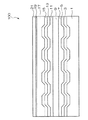
以下に、図1を参照して、本発明の光ディスクの例示的一態様を示す。ここで、図1は、本発明の光ディスクの一態様を示す概略断面図である。なお、当該図面は、理解を容易にするため、誇張して表現している。
図1に示すように、光ディスク100は、基板1、記録層3、反射層5、保護層7、接着層9、保護層11、反射層13、画像記録層15、樹脂層(ダミー基板)17、プライマー層19、及び反射防止層21がこの順に設けられてなる。
このような光ディスク100は、以下ようにして作製される。
まず、基板1上に、記録層3、反射層5、及び保護層7を順次形成し、第1の積層体を形成する。
また、ダミー基板17の一方の面に、画像記録層15、反射層13、及び保護層11を順次形成する。そして、ダミー基板17の他方の面に、予めプライマー層19が設けられている反射防止層21を貼り合せて、第2の積層体を形成する。なお、第2の積層体の形成においては、ダミー基板17に反射防止層21を貼り合せる工程と、ダミー基板17に画像記録層15等を形成する工程と、はどちらを先に行ってもよい。
そして、第1の積層体と第2の積層体とを、保護層7及び保護層11を貼り合わせ面として、接着層9にて貼り合せる。
このようにして、本発明の光ディスク100は作製される。
Hereinafter, an exemplary embodiment of the optical disk of the present invention will be described with reference to FIG. Here, FIG. 1 is a schematic sectional view showing an embodiment of the optical disk of the present invention. Note that the drawings are exaggerated for easy understanding.
As shown in FIG. 1, an
Such an
First, the recording layer 3, the reflective layer 5, and the protective layer 7 are sequentially formed on the substrate 1 to form a first laminate.
Further, the image recording layer 15, the reflective layer 13, and the
And the 1st laminated body and the 2nd laminated body are bonded by the contact bonding layer 9 by using the protective layer 7 and the
In this way, the
本発明の光ディスクは、レーベル面側に、画像記録層上に形成される樹脂層(ダミー基板等)表面に、低屈折率の反射防止層が形成されている。この構成により、樹脂層への映り込みが防止され、その結果、画像記録層に形成された可視画像のコントラストが向上するものである。 In the optical disk of the present invention, a low-refractive index antireflection layer is formed on the surface of a resin layer (such as a dummy substrate) formed on the image recording layer on the label surface side. With this configuration, reflection on the resin layer is prevented, and as a result, the contrast of the visible image formed on the image recording layer is improved.
(画像記録方法)
本発明の光ディスクの画像記録層への画像記録は、本発明の光ディスクと、少なくとも該光ディスクの画像記録層への画像情報の記録が可能な記録装置と、を用いて行う。
以下、先ず、本発明の光ディスクへの記録に用いられる記録装置について説明する。
(Image recording method)
Image recording on the image recording layer of the optical disc of the present invention is performed using the optical disc of the present invention and a recording apparatus capable of recording image information on at least the image recording layer of the optical disc.
First, a recording apparatus used for recording on an optical disk according to the present invention will be described.
本発明の光ディスクにおいて、画像記録層への画像の記録、及び記録層への光情報の記録は、両層への記録機能を有する1つの光ディスクドライブ(記録装置)で行うことができる。このように1つの光ディスクドライブを使用する場合、画像記録層及び記録層のいずれか一方の層への記録を行った後、裏返して他方の層に記録を行うことができる。画像記録層への可視画像の記録をする機能を有する光ディスクドライブとしては、例えば、特開2003−203348号公報、特開2003−242750号公報等に記載されている。 In the optical disc of the present invention, recording of an image on the image recording layer and recording of optical information on the recording layer can be performed by one optical disc drive (recording apparatus) having a recording function on both layers. When one optical disk drive is used as described above, after recording on one of the image recording layer and the recording layer, it can be turned over and recording can be performed on the other layer. Examples of the optical disc drive having a function of recording a visible image on the image recording layer are described in JP2003-203348A, JP2003-242750A, and the like.
記録層に光情報を記録する、及び、画像記録層に可視画像を記録する記録装置は、レーザー光を照射するレーザーピックアップと、光ディスクを回転させる回転機構とを少なくとも有する。このような記録装置の構成自体は周知である。 A recording apparatus that records optical information on a recording layer and records a visible image on an image recording layer includes at least a laser pickup that emits laser light and a rotation mechanism that rotates an optical disc. The configuration of such a recording apparatus itself is well known.
このような構成の記録装置を用いた画像記録層への可視画像の記録に際し、記録装置は、前記レーザーピックアップを、前記光ディスクの画像記録層に形成されたトラッキング用の溝によりトラッキングして、光ディスクの面に沿って相対移動させ、該相対移動に同期してレーザー光を、画像形成しようとする文字、絵等の画像データに応じて変調して画像記録層に向けて照射して可視画像を記録する。このような構成は、例えば、特開2002−203321号公報等に記載されている。 When recording a visible image on the image recording layer using the recording apparatus having such a configuration, the recording apparatus tracks the laser pickup by a tracking groove formed in the image recording layer of the optical disk, and The laser beam is modulated in accordance with image data such as characters and pictures to be imaged and irradiated to the image recording layer in synchronization with the relative movement, and a visible image is irradiated. Record. Such a configuration is described in, for example, Japanese Patent Application Laid-Open No. 2002-203321.
(情報記録方法)
次いで、記録層への情報(デジタル情報)の記録について説明する。記録層が色素型の場合、まず、未記録の前述の光ディスクを所定の記録線速度にて回転させながら、レーザーピックアップからレーザー光を照射する。この照射光により、記録層の色素がその光を吸収して局所的に温度上昇し、所望の空隙(ピット)が生成してその光学特性が変わることにより情報が記録される。
(Information recording method)
Next, recording of information (digital information) on the recording layer will be described. When the recording layer is a dye type, first, laser light is irradiated from a laser pickup while rotating the above-mentioned unrecorded optical disk at a predetermined recording linear velocity. By this irradiation light, the dye in the recording layer absorbs the light and the temperature rises locally, and a desired void (pit) is generated and its optical characteristics are changed to record information.
レーザー光の記録波形は、1つのピットの形成する際には、パルス列でも1パルスでもかまわない。実際に記録しようとする長さ(ピットの長さ)に対する割合が重要である。
レーザー光のパルス幅としては、実際に記録しようとする長さに対して20〜95%の範囲が好ましく、30〜90%の範囲がより好ましく、35〜85%の範囲が更に好ましい。ここで、記録波形がパルス列の場合には、その和が上記の範囲にあることを指す。
The recording waveform of the laser beam may be a pulse train or one pulse when one pit is formed. The ratio to the actual recording length (pit length) is important.
The pulse width of the laser beam is preferably in the range of 20 to 95%, more preferably in the range of 30 to 90%, and still more preferably in the range of 35 to 85% with respect to the length to be actually recorded. Here, when the recording waveform is a pulse train, the sum is in the above range.
レーザー光のパワーとしては、記録線速度によって異なるが、記録線速度が3.5m/sの場合、1〜100mWの範囲が好ましく、3〜50mWの範囲がより好ましく、5〜20mWの範囲が更に好ましい。また、記録線速度が2倍になった場合には、レーザー光のパワーの好ましい範囲は、それぞれ21/2倍となる。 The power of the laser beam varies depending on the recording linear velocity, but when the recording linear velocity is 3.5 m / s, the range of 1 to 100 mW is preferable, the range of 3 to 50 mW is more preferable, and the range of 5 to 20 mW is further increased. preferable. When the recording linear velocity is doubled, the preferable range of the laser beam power is 21/2 times, respectively.
また、記録密度を高めるために、ピックアップに使用される対物レンズのNAは0.55以上が好ましく、0.60以上がより好ましい。 In order to increase the recording density, the NA of the objective lens used for the pickup is preferably 0.55 or more, and more preferably 0.60 or more.
本発明においては、記録光として350〜850nmの範囲の発振波長を有する半導体レーザーを用いることができる。 In the present invention, a semiconductor laser having an oscillation wavelength in the range of 350 to 850 nm can be used as the recording light.
一方、記録層が相変化型の場合について説明する。相変化型の場合は、記録層は前述の材質から構成され、レーザー光の照射によって結晶相と非晶相との相変化を繰り返すことができる。
情報記録時は、集中したレーザー光パルスを短時間照射し、相変化記録層を部分的に溶融する。溶融した部分は熱拡散により急冷され、固化し、非晶状態の記録マークが形成される。また、消去時には、記録マーク部分にレーザー光を照射し、記録層の融点以下、結晶化温度以上の温度に加熱し、かつ、除冷することによって、非晶状態の記録マークを結晶化し、もとの未記録状態に戻す。
On the other hand, a case where the recording layer is a phase change type will be described. In the case of the phase change type, the recording layer is made of the above-described material, and the phase change between the crystalline phase and the amorphous phase can be repeated by irradiation with laser light.
At the time of information recording, a concentrated laser light pulse is irradiated for a short time to partially melt the phase change recording layer. The melted portion is rapidly cooled by heat diffusion and solidified to form an amorphous recording mark. During erasing, the recording mark portion is irradiated with laser light, heated to a temperature below the melting point of the recording layer and above the crystallization temperature, and then cooled to crystallize the amorphous recording mark. Return to the unrecorded state.
1・・・基板
3・・・記録層
5・・・反射層
7・・・保護層
9・・・接着層
11・・・保護層
13・・・反射層
15・・・画像記録層
17・・・樹脂層(ダミー基板)
19・・・プライマー層
21・・・反射防止層
100・・・光ディスク
DESCRIPTION OF SYMBOLS 1 ... Substrate 3 ... Recording layer 5 ... Reflective layer 7 ... Protective layer 9 ...
19 ...
Claims (2)
Priority Applications (1)
| Application Number | Priority Date | Filing Date | Title |
|---|---|---|---|
| JP2004344790A JP2006155751A (en) | 2004-11-29 | 2004-11-29 | Optical disk |
Applications Claiming Priority (1)
| Application Number | Priority Date | Filing Date | Title |
|---|---|---|---|
| JP2004344790A JP2006155751A (en) | 2004-11-29 | 2004-11-29 | Optical disk |
Publications (1)
| Publication Number | Publication Date |
|---|---|
| JP2006155751A true JP2006155751A (en) | 2006-06-15 |
Family
ID=36633860
Family Applications (1)
| Application Number | Title | Priority Date | Filing Date |
|---|---|---|---|
| JP2004344790A Pending JP2006155751A (en) | 2004-11-29 | 2004-11-29 | Optical disk |
Country Status (1)
| Country | Link |
|---|---|
| JP (1) | JP2006155751A (en) |
Cited By (2)
| Publication number | Priority date | Publication date | Assignee | Title |
|---|---|---|---|---|
| EP1950745A1 (en) * | 2005-09-30 | 2008-07-30 | Yamaha Corporation | Optical disc image formation device, optical disc image formation method, and optical disc |
| WO2019069984A1 (en) * | 2017-10-06 | 2019-04-11 | 三菱ケミカル株式会社 | Optical disc and method for manufacturing same |
-
2004
- 2004-11-29 JP JP2004344790A patent/JP2006155751A/en active Pending
Cited By (6)
| Publication number | Priority date | Publication date | Assignee | Title |
|---|---|---|---|---|
| EP1950745A1 (en) * | 2005-09-30 | 2008-07-30 | Yamaha Corporation | Optical disc image formation device, optical disc image formation method, and optical disc |
| EP1950745A4 (en) * | 2005-09-30 | 2009-01-21 | Yamaha Corp | Optical disc image formation device, optical disc image formation method, and optical disc |
| US7813245B2 (en) | 2005-09-30 | 2010-10-12 | Yamaha Corporation | Optical disk image forming device, optical disk image forming method and optical disk |
| WO2019069984A1 (en) * | 2017-10-06 | 2019-04-11 | 三菱ケミカル株式会社 | Optical disc and method for manufacturing same |
| JPWO2019069984A1 (en) * | 2017-10-06 | 2020-09-17 | シーエムシー マグネティクス コーポレーション | Optical discs and methods for manufacturing optical discs |
| JP7183171B2 (en) | 2017-10-06 | 2022-12-05 | シーエムシー マグネティクス コーポレーション | Optical disc and optical disc manufacturing method |
Similar Documents
| Publication | Publication Date | Title |
|---|---|---|
| TWI302930B (en) | ||
| US20070237051A1 (en) | Optical Recording Medium and Recording Method | |
| JP2006260728A (en) | Optical disk | |
| JP4213568B2 (en) | Information recording method | |
| JP4077781B2 (en) | Visible information recording method and recording apparatus for optical information recording medium | |
| US20070269652A1 (en) | Optical Disk | |
| JP2005116126A (en) | Optical information recording medium | |
| JP2006155751A (en) | Optical disk | |
| JP2006260730A (en) | Optical disk and optical recording method | |
| JP2006120188A (en) | Optical information recording medium and its manufacturing method | |
| JP2006107620A (en) | Optical disk | |
| JP2006031899A (en) | Optical disk | |
| JP2006040440A (en) | Image recording method to optical disk | |
| JP2005285167A (en) | Optical recording medium | |
| JP2006228278A (en) | Optical disk | |
| JP2006031883A (en) | Optical disk | |
| JP2006155692A (en) | Optical disk | |
| JP2006107670A (en) | Optical disk | |
| JP2006107618A (en) | Optical disk | |
| JP2006031882A (en) | Optical disk and image forming method | |
| JP2008041164A (en) | Optical information recording medium and manufacturing method therefor | |
| JP2008084458A (en) | Optical recording medium | |
| JP2006107619A (en) | Optical disk | |
| JP2006260729A (en) | Optical disk | |
| JP2008507794A (en) | Optical recording medium |
Legal Events
| Date | Code | Title | Description |
|---|---|---|---|
| A621 | Written request for application examination |
Free format text: JAPANESE INTERMEDIATE CODE: A621 Effective date: 20070216 |
|
| A711 | Notification of change in applicant |
Free format text: JAPANESE INTERMEDIATE CODE: A712 Effective date: 20070216 |
|
| A977 | Report on retrieval |
Free format text: JAPANESE INTERMEDIATE CODE: A971007 Effective date: 20080609 |
|
| A131 | Notification of reasons for refusal |
Free format text: JAPANESE INTERMEDIATE CODE: A131 Effective date: 20080617 |
|
| A02 | Decision of refusal |
Free format text: JAPANESE INTERMEDIATE CODE: A02 Effective date: 20081021 |