EP2011128B1 - Verfahren zur dimensionierung einer abtrennvorrichtung für überspannungsableiter - Google Patents
Verfahren zur dimensionierung einer abtrennvorrichtung für überspannungsableiter Download PDFInfo
- Publication number
- EP2011128B1 EP2011128B1 EP07727670.7A EP07727670A EP2011128B1 EP 2011128 B1 EP2011128 B1 EP 2011128B1 EP 07727670 A EP07727670 A EP 07727670A EP 2011128 B1 EP2011128 B1 EP 2011128B1
- Authority
- EP
- European Patent Office
- Prior art keywords
- switching
- force
- tongue
- movement
- point
- Prior art date
- Legal status (The legal status is an assumption and is not a legal conclusion. Google has not performed a legal analysis and makes no representation as to the accuracy of the status listed.)
- Active
Links
- 238000000034 method Methods 0.000 title claims description 10
- 230000008569 process Effects 0.000 title claims description 10
- 229910000679 solder Inorganic materials 0.000 claims description 19
- 230000005540 biological transmission Effects 0.000 claims description 6
- 239000000463 material Substances 0.000 claims description 6
- 230000009471 action Effects 0.000 claims description 5
- 238000009826 distribution Methods 0.000 claims description 5
- 238000006073 displacement reaction Methods 0.000 claims description 4
- 230000015572 biosynthetic process Effects 0.000 claims description 2
- 230000001681 protective effect Effects 0.000 claims 1
- 238000000926 separation method Methods 0.000 description 34
- 230000000694 effects Effects 0.000 description 16
- 229910052751 metal Inorganic materials 0.000 description 11
- 239000002184 metal Substances 0.000 description 11
- 238000005476 soldering Methods 0.000 description 10
- 150000002739 metals Chemical class 0.000 description 7
- 230000036316 preload Effects 0.000 description 7
- 230000006870 function Effects 0.000 description 6
- 238000010438 heat treatment Methods 0.000 description 6
- 238000005219 brazing Methods 0.000 description 5
- 238000001816 cooling Methods 0.000 description 4
- 230000007423 decrease Effects 0.000 description 4
- 230000003247 decreasing effect Effects 0.000 description 4
- 230000008901 benefit Effects 0.000 description 3
- 230000001419 dependent effect Effects 0.000 description 3
- 238000013461 design Methods 0.000 description 3
- 238000010791 quenching Methods 0.000 description 3
- 230000000171 quenching effect Effects 0.000 description 3
- 230000001960 triggered effect Effects 0.000 description 3
- PXHVJJICTQNCMI-UHFFFAOYSA-N Nickel Chemical compound [Ni] PXHVJJICTQNCMI-UHFFFAOYSA-N 0.000 description 2
- 235000014676 Phragmites communis Nutrition 0.000 description 2
- 230000000295 complement effect Effects 0.000 description 2
- 239000004020 conductor Substances 0.000 description 2
- 230000002950 deficient Effects 0.000 description 2
- 238000009413 insulation Methods 0.000 description 2
- 239000002655 kraft paper Substances 0.000 description 2
- 230000013011 mating Effects 0.000 description 2
- 239000000155 melt Substances 0.000 description 2
- 229910001092 metal group alloy Inorganic materials 0.000 description 2
- 230000004048 modification Effects 0.000 description 2
- 238000012986 modification Methods 0.000 description 2
- 238000013021 overheating Methods 0.000 description 2
- 230000003068 static effect Effects 0.000 description 2
- RTAQQCXQSZGOHL-UHFFFAOYSA-N Titanium Chemical compound [Ti] RTAQQCXQSZGOHL-UHFFFAOYSA-N 0.000 description 1
- 230000001133 acceleration Effects 0.000 description 1
- 238000013459 approach Methods 0.000 description 1
- 230000008859 change Effects 0.000 description 1
- 238000000576 coating method Methods 0.000 description 1
- 230000006835 compression Effects 0.000 description 1
- 238000007906 compression Methods 0.000 description 1
- 238000010276 construction Methods 0.000 description 1
- 230000006378 damage Effects 0.000 description 1
- 238000012217 deletion Methods 0.000 description 1
- 230000037430 deletion Effects 0.000 description 1
- 238000010586 diagram Methods 0.000 description 1
- 210000003746 feather Anatomy 0.000 description 1
- 230000000977 initiatory effect Effects 0.000 description 1
- 230000003993 interaction Effects 0.000 description 1
- 238000002955 isolation Methods 0.000 description 1
- 230000014759 maintenance of location Effects 0.000 description 1
- 238000004519 manufacturing process Methods 0.000 description 1
- 238000002844 melting Methods 0.000 description 1
- 230000008018 melting Effects 0.000 description 1
- 239000000203 mixture Substances 0.000 description 1
- 229910052759 nickel Inorganic materials 0.000 description 1
- 230000009467 reduction Effects 0.000 description 1
- 230000003716 rejuvenation Effects 0.000 description 1
- 239000012858 resilient material Substances 0.000 description 1
- 230000035939 shock Effects 0.000 description 1
- 239000000725 suspension Substances 0.000 description 1
- 230000003685 thermal hair damage Effects 0.000 description 1
- 239000010936 titanium Substances 0.000 description 1
- 229910052719 titanium Inorganic materials 0.000 description 1
- 238000012546 transfer Methods 0.000 description 1
Images


Classifications
-
- H—ELECTRICITY
- H01—ELECTRIC ELEMENTS
- H01H—ELECTRIC SWITCHES; RELAYS; SELECTORS; EMERGENCY PROTECTIVE DEVICES
- H01H37/00—Thermally-actuated switches
- H01H37/74—Switches in which only the opening movement or only the closing movement of a contact is effected by heating or cooling
- H01H37/76—Contact member actuated by melting of fusible material, actuated due to burning of combustible material or due to explosion of explosive material
- H01H37/761—Contact member actuated by melting of fusible material, actuated due to burning of combustible material or due to explosion of explosive material with a fusible element forming part of the switched circuit
-
- H—ELECTRICITY
- H01—ELECTRIC ELEMENTS
- H01C—RESISTORS
- H01C7/00—Non-adjustable resistors formed as one or more layers or coatings; Non-adjustable resistors made from powdered conducting material or powdered semi-conducting material with or without insulating material
- H01C7/10—Non-adjustable resistors formed as one or more layers or coatings; Non-adjustable resistors made from powdered conducting material or powdered semi-conducting material with or without insulating material voltage responsive, i.e. varistors
- H01C7/12—Overvoltage protection resistors
- H01C7/126—Means for protecting against excessive pressure or for disconnecting in case of failure
-
- H—ELECTRICITY
- H01—ELECTRIC ELEMENTS
- H01H—ELECTRIC SWITCHES; RELAYS; SELECTORS; EMERGENCY PROTECTIVE DEVICES
- H01H37/00—Thermally-actuated switches
- H01H37/74—Switches in which only the opening movement or only the closing movement of a contact is effected by heating or cooling
- H01H37/76—Contact member actuated by melting of fusible material, actuated due to burning of combustible material or due to explosion of explosive material
- H01H37/761—Contact member actuated by melting of fusible material, actuated due to burning of combustible material or due to explosion of explosive material with a fusible element forming part of the switched circuit
- H01H2037/762—Contact member actuated by melting of fusible material, actuated due to burning of combustible material or due to explosion of explosive material with a fusible element forming part of the switched circuit using a spring for opening the circuit when the fusible element melts
- H01H2037/763—Contact member actuated by melting of fusible material, actuated due to burning of combustible material or due to explosion of explosive material with a fusible element forming part of the switched circuit using a spring for opening the circuit when the fusible element melts the spring being a blade spring
Definitions
- the invention relates to a disconnecting device for a surge arrester whose switching movement is performed by a switching tongue, according to claim 1.
- the solder Under the influence of a heating, whose heat source preferably forms a surge protection component to be monitored, the solder is liquefied and separated as a result of thereby triggered switching movement of a specially designed part of the separation device, an electrical connection.
- the part of the separating device, which performs the switching movement is, for example after DE 295 19 313 U1 biased by a spring force oriented in the switching direction. The switching movement reaches its absolute end point as soon as the preload force of this spring is used up.
- Disconnecting devices according to the prior art are known as a disadvantage that the biasing force, if it acts permanently on the Lotstelle, already without thermal influence can cause a purely mechanical, unintentional triggering.
- a certain biasing force is necessary to achieve a correspondingly effective switching movement, i. that a sufficient switching path (separation distance) and a sufficient switching speed can be achieved.
- Both the switching path and the switching speed are parameters that determine the performance (switching capacity) of the separating device. Since with increasing switching path, a purely mechanical biasing force decreases rapidly, it is very difficult to ensure on the one hand over the entire switching path sufficient switching speed and on the other hand to limit the biasing force on the Lotstelle to a value that excludes with sufficient certainty a purely mechanically induced false triggering. In practice, therefore, a compromise is required, which allows a sufficient biasing force depending on the execution of the Lotstelle, the Lotmenge and finally also the composition of the solder. This requires a stable manufacturing process, especially with regard to must be redefined on the introduction of lead-free solders and usually requires a further reduction of the preload force.
- the biasing force should be able to be increased to the extent that on the one hand, an improved switching power on the switching path and the switching speed results, on the other hand, however, the risk of a purely mechanical triggering caused thereby does not exist.
- the forces F1 / F2 and F3 can be generated as independently organized individual forces from one or more of the same or different energy stores.
- the total prestressing force which acts on the soldering point is composed of at least two partial forces whose force effects (Effective directions) reinforce in the direction of switching movement as needed complementary.
- first biasing force F1 which acts permanently on the Lotstelle, also act one or more other forces demand-oriented by e.g. At normal soldering temperature are almost ineffective and only with increasing soldering temperature or during the separation or switching process bring their force effect.
- This force influence or distribution developed according to demand can be used as a function of state or temperature continuously or abruptly starting from a certain state of the switch position and / or a certain temperature.
- the invention is based on an increased force acting on the separating element during the entire separation process, i. during the Ausloöt- and the subsequent switching phase, which is influenced or supported by additional thermal and / or mechanical effects. This is e.g. then the case when a switching tongue used as a separating element itself supports the thermal force action or this force is even formed out of itself, e.g. is made of a material having the required mechanical / thermal properties.
- the switching tongue is formed from a molded part, at the first aus convinceddem end a contact clip for external contact with a male part and at the second expiring end of a specially trained or formable Lotspitze is formed.
- This Lotspitze is connected via a defined Lotstelle with the active, serving in case of failure as a heat source part of the arrester and thus forms an electrical / thermal connection using the described Preload force F1 is extinguished at the corresponding temperature influence, executes a switching movement. Due to the switching movement, the circuit is permanently interrupted by the now faulty arrester.
- a second biasing force F2 is required intervention in the separation process.
- this can be effected thermally, e.g. Already while the soldering point is "heated up” is increasing steadily or suddenly and so supports the Auslötvorgang.
- the separation process starting after the brazing operation can be assisted by the biasing force F2 by acting so that the separation process undergoes an additional "acceleration", e.g. the switching path is increased by a further opening of the separation path by deformation of the switching tongue.
- the electrical separation is improved, which is particularly advantageous at higher system voltages.
- the predominantly thermally induced prestressing force acting together with the first pretensioning force F1 is referred to as F2 and the preloading force acting predominantly mechanically together with F1 after the soldering operation is referred to as the shifting force F3.
- the switching tongue consists of a metallic, electrically conductive material which is deformable under the influence of heat.
- Such metals according to the prior art, have two different stable states of formation which are temperature-dependent.
- the second stable state which sets in under the influence of heat, on the other hand corresponds to the opened state of the separating device, so that with increasing heating, the bias voltage increases (steadily or abruptly) and thus increases the mechanical prestressing on the soldering point.
- a demand-based bias is generated, which ultimately also leads to high switching speeds, even with large switching paths.
- bi-metals are suitable for providing such a function.
- the memory metals consist of a metal alloy (eg nickel / titanium).
- the bimetals where the tendency to go into the second stable state increases steadily with increasing temperature, the memory metals have a certain temperature point at which they move abruptly in the manner of a switching movement from one state to the other and there remain when the temperature that led to the tripping has fallen off again.
- the embodiment of a switching tongue is conceivable, which generates in addition to the mentioned thermal effect of a biasing force F2 and the first, mechanically induced biasing force F1 by all or part of a combination of one of the mentioned thermal materials with a resilient material.
- both a specific area and the entire switching tongue in sandwich construction can be equipped with the thermally reacting metal.
- a mechanical tension or compression spring for generating the biasing force F1 is possibly replaced by the resilient effect of the reed tongue material.
- the achievable effect of such a combination is the same as in the embodiment according to the first variant with the functionally separate elements for generating the force effect F1 / F2.
- An advantage may arise in certain applications arise, for example, where there is a risk that the mechanical suspension of the spring for the biasing force F1 triggers (eg by mechanical shocks) or space requirements require a compact design of the separation device according to the invention.
- the biasing force F1 decreases steadily during the switching movement with increasing switching path.
- This effect can be compensated only partially by the biasing force F2, since this partial force unfolds only in the Auslötphase and after the heat supply is interrupted by the separation process, this force decreases more or less steadily.
- a further force F3 is provided according to the invention, which unfolds during the switching operation and thus at least partially compensates for the decreasing effect of F1 or F2 .
- the provision of this additional force takes place exclusively during the switching process and unfolds in the same direction relative to the pretensioning forces F1 / F2, but inversely offset in time. It is derived from the movement of the switching tongue by the force ratio is influenced by changing force and or leverage effects by a constant displacement of a power transmission point along the switching tongue so that the resulting force F3 increases steadily with increasing switching path.
- the invention provides a separation device for surge arresters with extended functional scope, which is that a first biasing force F1 is supported according to the prior art by at least one second biasing force F2 or switching force F3 according to the invention as needed to the triggering and switching characteristic to improve, on the one hand reduces the force on the Lotstelle at normal ambient temperature and on the other hand, the Abtrennweg or the separation speed compared to the prior art is increased.
- the separating means of the separating device according to the invention are located together with the over-voltage protection element to be monitored preferably in the attachable upper part of a two-part housing, but are in principle also a one-piece arrangement can be realized.
- the upper part has means for contacting with a lower part and a display window on which the switching state of the separating device is optically displayed.
- the lower part contacted via corresponding mating contacts the upper part and also has connection means for the outer terminals.
- the active element represents a surge-limiting or a overvoltage-switching component which is monitored by the separating device for exceeding a specific heating temperature.
- Exceeding given temperature values is considered to be the defective state of the active device (e.g., spark gap and / or varistor), requiring its disconnection from the power supply via the disconnect device.
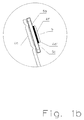
- FIG. 1a shows the upper part of a basic embodiment of a pluggable surge arrester, on which the invention essentially builds.
- both contact pieces (4, 6) consist of a single piece as a stamped, drawn or stamped part of a preferably thermally deformable and / or resilient and yet highly conductive material, at whose end or expression respectively contact springs (4b , 6b) or contact bracket (6a) for contacting the lower part or the arrester element (5) are integrally formed.
- a first of the two contact pieces (4) is formed in its design or configuration as a switching tongue (4c) of a separating device with extended properties, wherein an embodiment of the switching tongue (4c) as a rail once without expression and in another embodiment with a is formed centrally arranged expression. It is essential that both versions of the contact pieces (4) consist of a single part. At its end is the solder pad (4d) whose solder connection (4f) melts at a concomitant with heating overload of the arrester element (5) on the contact (5a) by heat transfer and with a switching movement of the switching tongue (4c) causes the intended shutdown ,
- the switching movement of the switching tongue (4c) results from a spring tension, which exerts indirectly via a separating block (2) a bias on the switching tongue (4c) and thus on the solder pad (4d).
- This bias corresponds to the biasing force F1.
- the separated switching tongue (4c) performs a correspondingly fast switching movement over a large opening path and thus provides a safe separation between the arrester element (5) and the cable formed by the switching tongue (4c) ago.
- the rotary movement performed by the separating block (2) is displayed in its end position (1b) in a viewing window (1a), so that the switching position of the separating block (2) can be recognized as a triggering state on the basis of its scarf surface (2d).
- the spring preload F1 for the switching tongue (4c) is generated by a spring (3) having its fixed point at the end of a housing groove (4a).
- the pressure force thus generated by the spring acts on the separating block (2) at point (2c), which in turn acts on the pivot bearing (2a) of the separating block and thus enables the already mentioned rotational movement.
- the spring preload F1 acts on the disconnect block (2) on the switching tongue (4c) and thus on the solder pad (4d). Further support can be obtained by the fact that the switching tongue (4c) itself generates a bias, which may consist of a spring clip or of a bimetal or memory metal strip.
- thermoformable metals that are designed to accept (at least) two stable, temperature dependent positions or shapes may be used to assist in the brazing operation.
- This effect is used in the invention so that the switching tongue with increasing temperature an increasing tensile force F2 in the switching direction learns and thus in addition to the spring force F1 increases the bias, which positively influences the initiated Auslöt- and the subsequent separation or switching operation.
- the bias of the tab generated by the combination F1 / F2 not only has an amplifying effect on the brazing operation, but additionally increases the reliability of the initiation of a switching operation by two independently acting, rectified forces.
- the Lotstelle that connects the tongue with the arrester element is designed and manufactured so that the separation takes place safely and at a time when no thermal damage can be foreseen by a superheated discharge element. This point is first determined by the choice of the solder, with the described mechanical bias provides a significant share to it. Furthermore, the Lotmenge at the Lotstelle (4f) (see FIG. 1b ) and the heat distribution at the solder pad be optimized.
- solder pad (4d) is formed so that it receives only a limited amount of solder by the end of the switching tongue (4c) as a contact blade (4d '), which dips as a mating contact in a slot-shaped aperture (5c) and with its protruding Part is soldered to the contact (5a) of the active element (5) is formed.
- highly heat-conductive metals or metal alloys or coatings are preferably used at least or exclusively in the area of the solder contact point (4d).
- the second contact piece (6) is formed so that it exerts via corresponding supports in the GeHouserenzteil which is designed for receiving the components, a contact pressure on the bracket (6 a) on the contact surface (5 b) of the arrester element (5) is soldered with this contact piece.
- the supports consist of braided webs, which at the same time increase the strength of the housing half part (1), so that a continuous contact pressure is also ensured by a corresponding rigidity of the carrier housing.
- both contact pieces (4, 6) are guided and held in position.
- the webs act as insulation for the contact pieces in certain areas or support or reinforce their shape there and thus make it possible for the contact pieces, for example can be mechanically loaded in the region of the plug contacts, without thereby deform.
- the generation of the switching force F3 according to the invention is based on FIGS. 2 to 4 explained. It unfolds its effect as soon as the Auslötvorgang is completed and moves the tongue in the direction of the end position for the open state. So it acts as the biasing force F2 demand-oriented but time-displaced together with F1.
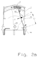
- FIGS. 2a and 2 B show a first example of the invention respectively in the closed and in the triggered state.
- the invention essential feature of this embodiment are two differently arranged pivot points, of which a first at the point (4e) of the switching tongue and a second at the point (2a) is associated with the Abtrennbock.
- the force effect of F1 biases the switching tongue in the direction of the switching movement via a fixed point (2b) on the disconnecting block in the untripped state.
- the separation is initiated under the action of the force F1 on the fixed point (2b) on the switching tongue, wherein the force of the fixed point on the Switching tongue exerts with increasing switching path in the direction of separation contact (4d) moves.
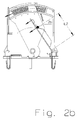
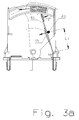
- FIGS. 3a and 3b show a second example of the invention in each case in the closed and in the triggered state.
- the triggering process up to the in FIG. 3b shown position of the tongue is so far identical to the one in FIG. 2a / 2 B already described.
- this variant of the invention has an additional function that, starting from this position of the switching position, which already represents the end position of the rotary movement through the Abtrennbock causes a further extension of the switching path.
- This switch position is in Figure 3c shown.
- the switching tongue (4c) used for this ( Figure 3d / 3e ) is formed from a spring material having in a certain area an expression with an arcuate web (4h).
- the over-arched bridge acts as an integrated spring clip. Due to the mechanical preload that the tongue learns by the overbending of the web or the spring clip acts in the soldered state, first a biasing force (F2 ') in the direction of Lotstelle, whereby the bias voltage is reduced in the switching direction by the spring force F1. After the Auslötvorgang is completed, the switching tongue sets under the predominant influence of F1 in the usual way from the Lotstelle by a switching movement in the direction of the end position.
- the overbend (4h) thereby undergoes an overstretching, so that it abruptly tilts in the opposite direction S2 ', whereby the switching tongue altogether performs a tilting movement by deformation of the web towards the end position and thus additionally increases the switching path beyond the actual end position of the switching movement S1 by the amount S2 ( Figure 3c ).
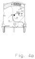
- FIGS. 4a / 4b show a third variant of the invention respectively in the soldered and in the soldered state.
- This variant has an approximately S-shaped pre-bent switching tongue (4c), as in FIG. 4b can be seen in the soldered state.
- the front portion of the tab In the closed state after FIG. 4a the front portion of the tab is bent into a U-shape, the open end (4d ') of which projects into a slot (5c) of the solder tab (5a) and is soldered therein.
- the fixed point (2b) of the Abtrennbocks transmits the biasing force F1 of the spring on the switching tongue and changed during the deletion following separation movement his point of attack so that it supports the separation movement.
- FIG. 5a shows by way of example the interaction of the individual partial forces F1, F2 and F3 during a Auslötvorganges by heating T of the Ableiteriatas to be monitored with subsequent separation of the switching tongue and the switching path, the switching tongue travels to the end stop.
- the Auslötvorgang is in the range A.
- the heating temperature T of the arrester increases starting at the ambient temperature T u until the Auslöttemperatur T A is reached.
- the arrester cools off again over time.
- overheating of the entire system which could develop in the worst case or lack of separation device to a fire hazard, avoided.
- the Auslötvorgangs increases the force of the biasing force F2 continuously, while the biasing force F1 permanently acts on the switching tongue and thus on the not soldered at this time Lotstelle.
- the soldering process is completed at time t2.
- the switching tongue is first significantly moved under the effect of decreasing with increasing switching path forces F1 and F2 towards the end position t3, while the force F3 in this area with means that in the explanations to the FIGS. 2 to 4 are described, increases to the end position.
- FIG. 5a also clearly shows that the force F2 essentially supports the brazing process (area A).
- Another object of the invention is that for the switching operation (area B), another force comes into action, which supports or replaces the decreasing with increasing shift travel spring force of F1 to achieve a high switching speed and a large switching path. Serves the switching force F3 after the means FIG. 2 to FIG. 4 provided.
- the cross section of the switching tongue is tapered at a suitable location. The cross-section of this taper determines the current that leads to a power-related shutdown.
- Another possibility is a quenching device that releases a quenching gas under the thermal influence of the arc.
- the separating block is designed so that it pushes between the separated parts of the switching tongue, wherein the lower part is hollow-walled and encloses the separated lower part of the switching tongue in the manner of a switching chamber. This offers the arc no further foot, whereby it is interrupted.
- the separating block or at least the hollow chamber consists of a material which releases a quenching gas under the influence of the arc, which additionally suppresses the expansion of the arc by cooling.
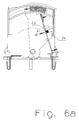
- FIGS. 6a and 6b show such, integrated in the switching tongue current fuse.
- FIG. 6a shows the switching tongue (4c), which in the region of the support point for the fixed point (2b) has a cross-sectional taper (4i), which is formed from a bore or expression.
- the divider block forms below the fixed point a switching chamber (2e), which separates the lower part of the switching tongue (4i ') during and after the current-related separation from the upper part (4i ") still connected to the soldering point, through the enclosure of the lower part the switching tongue, this area is electrically separated from the other parts by spacing and insulation ( FIG. 6b ).
Landscapes
- Engineering & Computer Science (AREA)
- Microelectronics & Electronic Packaging (AREA)
- Physics & Mathematics (AREA)
- Electromagnetism (AREA)
- Chemical & Material Sciences (AREA)
- Combustion & Propulsion (AREA)
- Fuses (AREA)
- Thermally Actuated Switches (AREA)
Priority Applications (1)
| Application Number | Priority Date | Filing Date | Title |
|---|---|---|---|
| SI200731785A SI2011128T1 (sl) | 2006-04-26 | 2007-04-03 | Postopek dimenzioniranja odklopnega stikala za prenapetostni odvodnik |
Applications Claiming Priority (3)
| Application Number | Priority Date | Filing Date | Title |
|---|---|---|---|
| DE102006019498 | 2006-04-26 | ||
| DE102006036598A DE102006036598A1 (de) | 2006-04-26 | 2006-08-04 | Verfahren zur Dimensionierung einer Abtrennvorrichtung für Überspannungsableiter |
| PCT/EP2007/053198 WO2007125000A1 (de) | 2006-04-26 | 2007-04-03 | Verfahren zur dimensionierung einer abtrennvorrichtung für überspannungsableiter |
Publications (2)
| Publication Number | Publication Date |
|---|---|
| EP2011128A1 EP2011128A1 (de) | 2009-01-07 |
| EP2011128B1 true EP2011128B1 (de) | 2016-03-30 |
Family
ID=38542467
Family Applications (1)
| Application Number | Title | Priority Date | Filing Date |
|---|---|---|---|
| EP07727670.7A Active EP2011128B1 (de) | 2006-04-26 | 2007-04-03 | Verfahren zur dimensionierung einer abtrennvorrichtung für überspannungsableiter |
Country Status (9)
| Country | Link |
|---|---|
| EP (1) | EP2011128B1 (ru) |
| JP (1) | JP5059099B2 (ru) |
| CN (1) | CN101427327B (ru) |
| DE (1) | DE102006036598A1 (ru) |
| ES (1) | ES2579908T3 (ru) |
| PL (1) | PL2011128T3 (ru) |
| RU (1) | RU2410781C2 (ru) |
| SI (1) | SI2011128T1 (ru) |
| WO (1) | WO2007125000A1 (ru) |
Cited By (2)
| Publication number | Priority date | Publication date | Assignee | Title |
|---|---|---|---|---|
| DE102017129660A1 (de) | 2017-07-10 | 2019-01-10 | DEHN + SÖHNE GmbH + Co. KG. | Anordnung zum Monitoring des Zustandes von Überspannungsableitern |
| DE102018114564A1 (de) | 2018-06-18 | 2019-12-19 | Dehn Se + Co Kg | Abtrennvorrichtung für einen Überspannungsableiter |
Families Citing this family (14)
| Publication number | Priority date | Publication date | Assignee | Title |
|---|---|---|---|---|
| DE102008029670B4 (de) * | 2008-06-24 | 2016-10-20 | Phoenix Contact Gmbh & Co. Kg | Überspannungsschutzelement |
| DE102008048644B4 (de) | 2008-08-01 | 2017-08-24 | DEHN + SÖHNE GmbH + Co. KG. | Überspannungsschutzgerät mit einem oder mehreren parallel geschalteten, in einer baulichen Einheit befindlichen überspannungsbegrenzenden Elementen |
| DE102009052400B3 (de) * | 2009-11-10 | 2011-05-12 | Phoenix Contact Gmbh & Co. Kg | Thermische Überlastschutzvorrichtung |
| DE102010038070B4 (de) * | 2010-08-06 | 2012-10-11 | Phoenix Contact Gmbh & Co. Kg | Thermische Überlastschutzvorrichtung |
| EP2541577A1 (en) * | 2011-06-30 | 2013-01-02 | Epcos Ag | Electric device |
| EP2541579B1 (en) | 2011-06-30 | 2015-11-04 | Epcos Ag | Electric device |
| DE102013202795C5 (de) * | 2013-02-20 | 2019-01-24 | Phoenix Contact Gmbh & Co. Kg | Reversible Abtrennvorrichtung |
| DE102013021936B3 (de) * | 2013-10-08 | 2015-02-12 | Dehn + Söhne Gmbh + Co. Kg | Kompakte, vorkonfektionierbare Überspannungsschutzvorrichtung |
| DE102015008136B4 (de) | 2014-09-05 | 2021-08-26 | Dehn Se + Co Kg | Schalteinrichtung für Überspannungsschutzgeräte |
| DE102016001767A1 (de) | 2015-11-09 | 2017-05-11 | DEHN + SÖHNE GmbH + Co. KG. | Schalteinrichtung für Überspannungsschutzgeräte |
| EP3166193B1 (de) | 2015-11-09 | 2018-01-31 | Dehn + Söhne Gmbh + Co Kg | Schalteinrichtung für überspannungsschutzgeräte |
| DE102018205549B3 (de) | 2018-04-12 | 2019-08-01 | Phoenix Contact Gmbh & Co. Kg | Abtrennelement und Ensemble aufweisend ein entsprechendes Abtrennelement und ein Überspannungsschutzelement |
| DE202018006119U1 (de) | 2018-06-18 | 2019-04-11 | Dehn + Söhne Gmbh + Co. Kg | Abtrennvorrichtung für einen Überspannungsableiter |
| GB2619066A (en) * | 2022-05-26 | 2023-11-29 | Eaton Intelligent Power Ltd | Overvoltage protection device with improved integrated overtemperature protection |
Family Cites Families (16)
| Publication number | Priority date | Publication date | Assignee | Title |
|---|---|---|---|---|
| DE2735624A1 (de) * | 1977-08-06 | 1979-02-08 | Standard Elektrik Lorenz Ag | Ueberspannungsschutzvorrichtung fuer fernsprechanlagen |
| JPS57107253U (ru) * | 1980-12-23 | 1982-07-02 | ||
| GB2096844A (en) * | 1981-04-10 | 1982-10-20 | Beswick Kenneth E Ltd | Electrical fuse |
| EP0076284A1 (en) * | 1981-04-10 | 1983-04-13 | Kenneth E Beswick Limited | Electrical fuse |
| JPS5895147U (ja) * | 1981-12-18 | 1983-06-28 | 松下電器産業株式会社 | 断路表示機構付サ−ジ吸収器 |
| JPS5916044U (ja) * | 1982-07-22 | 1984-01-31 | 東邦電気株式会社 | 回路しや断器の温度ヒユ−ズ装置 |
| JPS6094753U (ja) * | 1983-12-02 | 1985-06-28 | 本郷 萬蔵 | 温度ヒユ−ズ |
| DE4118738C1 (ru) * | 1991-06-05 | 1992-12-24 | Krone Ag, 1000 Berlin, De | |
| JP2754334B2 (ja) * | 1994-06-22 | 1998-05-20 | ウチヤ・サーモスタット株式会社 | ヒューズスプリング内蔵サーモスタット |
| DE4437122C2 (de) * | 1994-10-01 | 1996-07-18 | Krone Ag | Überspannungsschutzstecker |
| CN2209383Y (zh) * | 1994-11-24 | 1995-10-04 | 西安无线电二厂 | 指示报警型浪涌吸收器 |
| DE29519313U1 (de) * | 1995-12-06 | 1996-01-25 | Dehn + Söhne GmbH + Co KG, 90489 Nürnberg | Überspannungsableiter |
| DE19717634C2 (de) * | 1997-04-25 | 2000-06-08 | Epcos Ag | Elektrisches Bauelement mit Sicherheitstrennvorrichtung |
| AT406207B (de) * | 1997-09-30 | 2000-03-27 | Felten & Guilleaume Ag Oester | Steckbarer überspannungsableiter |
| DE19819792A1 (de) * | 1998-05-04 | 1999-11-18 | Kopp Heinrich Ag | Mehrpoliger Schalter |
| CN2588521Y (zh) * | 2002-12-25 | 2003-11-26 | 王保巨 | 热爆式脱离器 |
-
2006
- 2006-08-04 DE DE102006036598A patent/DE102006036598A1/de not_active Withdrawn
-
2007
- 2007-04-03 EP EP07727670.7A patent/EP2011128B1/de active Active
- 2007-04-03 SI SI200731785A patent/SI2011128T1/sl unknown
- 2007-04-03 WO PCT/EP2007/053198 patent/WO2007125000A1/de active Application Filing
- 2007-04-03 RU RU2008145659/07A patent/RU2410781C2/ru not_active IP Right Cessation
- 2007-04-03 PL PL07727670.7T patent/PL2011128T3/pl unknown
- 2007-04-03 JP JP2009507016A patent/JP5059099B2/ja not_active Expired - Fee Related
- 2007-04-03 ES ES07727670.7T patent/ES2579908T3/es active Active
- 2007-04-03 CN CN2007800146088A patent/CN101427327B/zh not_active Expired - Fee Related
Cited By (6)
| Publication number | Priority date | Publication date | Assignee | Title |
|---|---|---|---|---|
| DE102017129660A1 (de) | 2017-07-10 | 2019-01-10 | DEHN + SÖHNE GmbH + Co. KG. | Anordnung zum Monitoring des Zustandes von Überspannungsableitern |
| WO2019011631A1 (de) | 2017-07-10 | 2019-01-17 | Dehn + Söhne Gmbh + Co. Kg | Anordnung zum monitoring des zustandes von überspannungsableitern |
| DE102017129660B4 (de) | 2017-07-10 | 2024-04-11 | Dehn Se | Anordnung zum Monitoring des Zustandes von Überspannungsableitern |
| DE102018114564A1 (de) | 2018-06-18 | 2019-12-19 | Dehn Se + Co Kg | Abtrennvorrichtung für einen Überspannungsableiter |
| US11476071B2 (en) | 2018-06-18 | 2022-10-18 | Dehn Se | Disconnecting device for a surge arrester |
| DE102018114564B4 (de) | 2018-06-18 | 2023-01-19 | Dehn Se | Überspannungsableiter |
Also Published As
| Publication number | Publication date |
|---|---|
| JP2009534804A (ja) | 2009-09-24 |
| ES2579908T3 (es) | 2016-08-17 |
| WO2007125000A1 (de) | 2007-11-08 |
| SI2011128T1 (sl) | 2016-07-29 |
| CN101427327B (zh) | 2011-04-06 |
| PL2011128T3 (pl) | 2016-09-30 |
| RU2410781C2 (ru) | 2011-01-27 |
| DE102006036598A1 (de) | 2007-10-31 |
| JP5059099B2 (ja) | 2012-10-24 |
| CN101427327A (zh) | 2009-05-06 |
| EP2011128A1 (de) | 2009-01-07 |
| RU2008145659A (ru) | 2010-06-10 |
Similar Documents
| Publication | Publication Date | Title |
|---|---|---|
| EP2011128B1 (de) | Verfahren zur dimensionierung einer abtrennvorrichtung für überspannungsableiter | |
| DE602005000540T2 (de) | Überspannungs-Schutzeinrichtung | |
| EP1958304B1 (de) | Steckbarer überspannungsableiter | |
| DE19941190B4 (de) | Wärmeschutzsicherung | |
| DE102011052805B4 (de) | Sicherung | |
| DE102008013447B4 (de) | Überspannungsableiter mit einem Gehäuse und mindestens einem Ableitelement | |
| DE112009004500B4 (de) | Temperaturwächter | |
| EP2126949A1 (de) | Auslösevorrichtung für eine thermosicherung | |
| EP0640242B1 (de) | Kontaktfederanordnung für ein relais zum führen und schalten hoher ströme | |
| EP0938116B1 (de) | Schalter | |
| AT521150A4 (de) | Pyrotechnischer Stromtrenner | |
| DE3823747C2 (ru) | ||
| DE19909059C2 (de) | Schalter mit Verschweißsicherung | |
| DE102018114564B4 (de) | Überspannungsableiter | |
| EP3258231A1 (de) | Elektromechanisches schutzschaltgerät mit einer überlastauslöseeinrichtung | |
| DE102019112680B4 (de) | Überspannungsschutzgerät | |
| DE2610951C3 (de) | Schutzschalter | |
| DE3729454C3 (de) | Kontaktelement für den Leistungsanschluß eines Schaltschrankeinschubs einer Niederspannungsschaltanlage | |
| EP0170186B1 (de) | Elektrische Sicherungseinrichtung mit einem Schmelzleiter | |
| DE19607756C1 (de) | Hochspannungs-Hochleistungs-Sicherung | |
| WO2019077038A1 (de) | Überspannungsschutzgerät | |
| DE2414884A1 (de) | Thermischer mikroschalter | |
| EP2070169B1 (de) | Überspannungsableiter mit mindestens einem ableitelement, insbesondere einem varistor, sowie mit einer abtrennvorrichtung | |
| DE102008049472A1 (de) | Überspannungsableiter mit mindestens einem Ableitelement, insbesondere einem Varistor, sowie mit einer Abtrennvorrichtung | |
| WO1987006399A1 (en) | Device for protecting a surge arrester against overheating |
Legal Events
| Date | Code | Title | Description |
|---|---|---|---|
| PUAI | Public reference made under article 153(3) epc to a published international application that has entered the european phase |
Free format text: ORIGINAL CODE: 0009012 |
|
| 17P | Request for examination filed |
Effective date: 20080814 |
|
| AK | Designated contracting states |
Kind code of ref document: A1 Designated state(s): AT BE BG CH CY CZ DE DK EE ES FI FR GB GR HU IE IS IT LI LT LU LV MC MT NL PL PT RO SE SI SK TR |
|
| AX | Request for extension of the european patent |
Extension state: AL BA HR MK RS |
|
| 17Q | First examination report despatched |
Effective date: 20110901 |
|
| DAX | Request for extension of the european patent (deleted) | ||
| REG | Reference to a national code |
Ref country code: DE Ref legal event code: R079 Ref document number: 502007014668 Country of ref document: DE Free format text: PREVIOUS MAIN CLASS: H01C0007120000 Ipc: H01H0037760000 |
|
| GRAP | Despatch of communication of intention to grant a patent |
Free format text: ORIGINAL CODE: EPIDOSNIGR1 |
|
| RIC1 | Information provided on ipc code assigned before grant |
Ipc: H01H 37/76 20060101AFI20151126BHEP |
|
| INTG | Intention to grant announced |
Effective date: 20151216 |
|
| GRAS | Grant fee paid |
Free format text: ORIGINAL CODE: EPIDOSNIGR3 |
|
| GRAA | (expected) grant |
Free format text: ORIGINAL CODE: 0009210 |
|
| AK | Designated contracting states |
Kind code of ref document: B1 Designated state(s): AT BE BG CH CY CZ DE DK EE ES FI FR GB GR HU IE IS IT LI LT LU LV MC MT NL PL PT RO SE SI SK TR |
|
| REG | Reference to a national code |
Ref country code: GB Ref legal event code: FG4D Free format text: NOT ENGLISH |
|
| REG | Reference to a national code |
Ref country code: CH Ref legal event code: EP |
|
| REG | Reference to a national code |
Ref country code: AT Ref legal event code: REF Ref document number: 786177 Country of ref document: AT Kind code of ref document: T Effective date: 20160415 |
|
| REG | Reference to a national code |
Ref country code: IE Ref legal event code: FG4D Free format text: LANGUAGE OF EP DOCUMENT: GERMAN |
|
| REG | Reference to a national code |
Ref country code: FR Ref legal event code: PLFP Year of fee payment: 10 |
|
| REG | Reference to a national code |
Ref country code: DE Ref legal event code: R096 Ref document number: 502007014668 Country of ref document: DE |
|
| REG | Reference to a national code |
Ref country code: LT Ref legal event code: MG4D |
|
| PG25 | Lapsed in a contracting state [announced via postgrant information from national office to epo] |
Ref country code: FI Free format text: LAPSE BECAUSE OF FAILURE TO SUBMIT A TRANSLATION OF THE DESCRIPTION OR TO PAY THE FEE WITHIN THE PRESCRIBED TIME-LIMIT Effective date: 20160330 Ref country code: GR Free format text: LAPSE BECAUSE OF FAILURE TO SUBMIT A TRANSLATION OF THE DESCRIPTION OR TO PAY THE FEE WITHIN THE PRESCRIBED TIME-LIMIT Effective date: 20160701 |
|
| PGFP | Annual fee paid to national office [announced via postgrant information from national office to epo] |
Ref country code: ES Payment date: 20160518 Year of fee payment: 10 |
|
| REG | Reference to a national code |
Ref country code: NL Ref legal event code: MP Effective date: 20160330 |
|
| REG | Reference to a national code |
Ref country code: ES Ref legal event code: FG2A Ref document number: 2579908 Country of ref document: ES Kind code of ref document: T3 Effective date: 20160817 |
|
| PG25 | Lapsed in a contracting state [announced via postgrant information from national office to epo] |
Ref country code: BE Free format text: LAPSE BECAUSE OF NON-PAYMENT OF DUE FEES Effective date: 20160430 Ref country code: SE Free format text: LAPSE BECAUSE OF FAILURE TO SUBMIT A TRANSLATION OF THE DESCRIPTION OR TO PAY THE FEE WITHIN THE PRESCRIBED TIME-LIMIT Effective date: 20160330 Ref country code: LV Free format text: LAPSE BECAUSE OF FAILURE TO SUBMIT A TRANSLATION OF THE DESCRIPTION OR TO PAY THE FEE WITHIN THE PRESCRIBED TIME-LIMIT Effective date: 20160330 Ref country code: LT Free format text: LAPSE BECAUSE OF FAILURE TO SUBMIT A TRANSLATION OF THE DESCRIPTION OR TO PAY THE FEE WITHIN THE PRESCRIBED TIME-LIMIT Effective date: 20160330 |
|
| PGFP | Annual fee paid to national office [announced via postgrant information from national office to epo] |
Ref country code: SI Payment date: 20160401 Year of fee payment: 10 |
|
| PG25 | Lapsed in a contracting state [announced via postgrant information from national office to epo] |
Ref country code: NL Free format text: LAPSE BECAUSE OF FAILURE TO SUBMIT A TRANSLATION OF THE DESCRIPTION OR TO PAY THE FEE WITHIN THE PRESCRIBED TIME-LIMIT Effective date: 20160330 |
|
| PG25 | Lapsed in a contracting state [announced via postgrant information from national office to epo] |
Ref country code: IS Free format text: LAPSE BECAUSE OF FAILURE TO SUBMIT A TRANSLATION OF THE DESCRIPTION OR TO PAY THE FEE WITHIN THE PRESCRIBED TIME-LIMIT Effective date: 20160730 Ref country code: EE Free format text: LAPSE BECAUSE OF FAILURE TO SUBMIT A TRANSLATION OF THE DESCRIPTION OR TO PAY THE FEE WITHIN THE PRESCRIBED TIME-LIMIT Effective date: 20160330 |
|
| PG25 | Lapsed in a contracting state [announced via postgrant information from national office to epo] |
Ref country code: SK Free format text: LAPSE BECAUSE OF FAILURE TO SUBMIT A TRANSLATION OF THE DESCRIPTION OR TO PAY THE FEE WITHIN THE PRESCRIBED TIME-LIMIT Effective date: 20160330 Ref country code: PT Free format text: LAPSE BECAUSE OF FAILURE TO SUBMIT A TRANSLATION OF THE DESCRIPTION OR TO PAY THE FEE WITHIN THE PRESCRIBED TIME-LIMIT Effective date: 20160801 Ref country code: RO Free format text: LAPSE BECAUSE OF FAILURE TO SUBMIT A TRANSLATION OF THE DESCRIPTION OR TO PAY THE FEE WITHIN THE PRESCRIBED TIME-LIMIT Effective date: 20160330 |
|
| PGFP | Annual fee paid to national office [announced via postgrant information from national office to epo] |
Ref country code: CZ Payment date: 20160527 Year of fee payment: 10 Ref country code: PL Payment date: 20160426 Year of fee payment: 10 |
|
| REG | Reference to a national code |
Ref country code: CH Ref legal event code: PL |
|
| REG | Reference to a national code |
Ref country code: DE Ref legal event code: R097 Ref document number: 502007014668 Country of ref document: DE |
|
| REG | Reference to a national code |
Ref country code: IE Ref legal event code: MM4A |
|
| PG25 | Lapsed in a contracting state [announced via postgrant information from national office to epo] |
Ref country code: LI Free format text: LAPSE BECAUSE OF NON-PAYMENT OF DUE FEES Effective date: 20160430 Ref country code: DK Free format text: LAPSE BECAUSE OF FAILURE TO SUBMIT A TRANSLATION OF THE DESCRIPTION OR TO PAY THE FEE WITHIN THE PRESCRIBED TIME-LIMIT Effective date: 20160330 Ref country code: CH Free format text: LAPSE BECAUSE OF NON-PAYMENT OF DUE FEES Effective date: 20160430 |
|
| PLBE | No opposition filed within time limit |
Free format text: ORIGINAL CODE: 0009261 |
|
| STAA | Information on the status of an ep patent application or granted ep patent |
Free format text: STATUS: NO OPPOSITION FILED WITHIN TIME LIMIT |
|
| PGFP | Annual fee paid to national office [announced via postgrant information from national office to epo] |
Ref country code: IT Payment date: 20160427 Year of fee payment: 10 |
|
| GBPC | Gb: european patent ceased through non-payment of renewal fee |
Effective date: 20160630 |
|
| 26N | No opposition filed |
Effective date: 20170103 |
|
| REG | Reference to a national code |
Ref country code: FR Ref legal event code: PLFP Year of fee payment: 11 |
|
| PG25 | Lapsed in a contracting state [announced via postgrant information from national office to epo] |
Ref country code: IE Free format text: LAPSE BECAUSE OF NON-PAYMENT OF DUE FEES Effective date: 20160403 Ref country code: GB Free format text: LAPSE BECAUSE OF NON-PAYMENT OF DUE FEES Effective date: 20160630 |
|
| REG | Reference to a national code |
Ref country code: AT Ref legal event code: MM01 Ref document number: 786177 Country of ref document: AT Kind code of ref document: T Effective date: 20160403 |
|
| PG25 | Lapsed in a contracting state [announced via postgrant information from national office to epo] |
Ref country code: AT Free format text: LAPSE BECAUSE OF NON-PAYMENT OF DUE FEES Effective date: 20160403 |
|
| PG25 | Lapsed in a contracting state [announced via postgrant information from national office to epo] |
Ref country code: CZ Free format text: LAPSE BECAUSE OF NON-PAYMENT OF DUE FEES Effective date: 20170403 |
|
| PG25 | Lapsed in a contracting state [announced via postgrant information from national office to epo] |
Ref country code: SI Free format text: LAPSE BECAUSE OF NON-PAYMENT OF DUE FEES Effective date: 20170404 |
|
| REG | Reference to a national code |
Ref country code: SI Ref legal event code: KO00 Effective date: 20180115 |
|
| REG | Reference to a national code |
Ref country code: FR Ref legal event code: PLFP Year of fee payment: 12 |
|
| PG25 | Lapsed in a contracting state [announced via postgrant information from national office to epo] |
Ref country code: IT Free format text: LAPSE BECAUSE OF NON-PAYMENT OF DUE FEES Effective date: 20170403 Ref country code: CY Free format text: LAPSE BECAUSE OF FAILURE TO SUBMIT A TRANSLATION OF THE DESCRIPTION OR TO PAY THE FEE WITHIN THE PRESCRIBED TIME-LIMIT Effective date: 20160330 Ref country code: HU Free format text: LAPSE BECAUSE OF FAILURE TO SUBMIT A TRANSLATION OF THE DESCRIPTION OR TO PAY THE FEE WITHIN THE PRESCRIBED TIME-LIMIT; INVALID AB INITIO Effective date: 20070403 |
|
| PG25 | Lapsed in a contracting state [announced via postgrant information from national office to epo] |
Ref country code: MC Free format text: LAPSE BECAUSE OF FAILURE TO SUBMIT A TRANSLATION OF THE DESCRIPTION OR TO PAY THE FEE WITHIN THE PRESCRIBED TIME-LIMIT Effective date: 20160330 Ref country code: MT Free format text: LAPSE BECAUSE OF FAILURE TO SUBMIT A TRANSLATION OF THE DESCRIPTION OR TO PAY THE FEE WITHIN THE PRESCRIBED TIME-LIMIT Effective date: 20160330 Ref country code: LU Free format text: LAPSE BECAUSE OF NON-PAYMENT OF DUE FEES Effective date: 20160403 Ref country code: TR Free format text: LAPSE BECAUSE OF FAILURE TO SUBMIT A TRANSLATION OF THE DESCRIPTION OR TO PAY THE FEE WITHIN THE PRESCRIBED TIME-LIMIT Effective date: 20160330 |
|
| REG | Reference to a national code |
Ref country code: ES Ref legal event code: FD2A Effective date: 20180705 |
|
| PG25 | Lapsed in a contracting state [announced via postgrant information from national office to epo] |
Ref country code: BG Free format text: LAPSE BECAUSE OF FAILURE TO SUBMIT A TRANSLATION OF THE DESCRIPTION OR TO PAY THE FEE WITHIN THE PRESCRIBED TIME-LIMIT Effective date: 20160330 Ref country code: ES Free format text: LAPSE BECAUSE OF NON-PAYMENT OF DUE FEES Effective date: 20170404 |
|
| PG25 | Lapsed in a contracting state [announced via postgrant information from national office to epo] |
Ref country code: PL Free format text: LAPSE BECAUSE OF NON-PAYMENT OF DUE FEES Effective date: 20170403 |
|
| REG | Reference to a national code |
Ref country code: DE Ref legal event code: R081 Ref document number: 502007014668 Country of ref document: DE Owner name: DEHN SE, DE Free format text: FORMER OWNER: DEHN + SOEHNE GMBH + CO. KG., 92318 NEUMARKT, DE Ref country code: DE Ref legal event code: R082 Ref document number: 502007014668 Country of ref document: DE Representative=s name: MEISSNER BOLTE PATENTANWAELTE RECHTSANWAELTE P, DE Ref country code: DE Ref legal event code: R081 Ref document number: 502007014668 Country of ref document: DE Owner name: DEHN SE + CO KG, DE Free format text: FORMER OWNER: DEHN + SOEHNE GMBH + CO. KG., 92318 NEUMARKT, DE Ref country code: DE Ref legal event code: R082 Ref document number: 502007014668 Country of ref document: DE Representative=s name: PRINZ & PARTNER MBB PATENTANWAELTE RECHTSANWAE, DE |
|
| REG | Reference to a national code |
Ref country code: DE Ref legal event code: R082 Ref document number: 502007014668 Country of ref document: DE Representative=s name: PRINZ & PARTNER MBB PATENT- UND RECHTSANWAELTE, DE Ref country code: DE Ref legal event code: R082 Ref document number: 502007014668 Country of ref document: DE Representative=s name: PRINZ & PARTNER MBB PATENTANWAELTE RECHTSANWAE, DE |
|
| PGFP | Annual fee paid to national office [announced via postgrant information from national office to epo] |
Ref country code: FR Payment date: 20210421 Year of fee payment: 15 |
|
| REG | Reference to a national code |
Ref country code: DE Ref legal event code: R081 Ref document number: 502007014668 Country of ref document: DE Owner name: DEHN SE, DE Free format text: FORMER OWNER: DEHN SE + CO KG, 92318 NEUMARKT, DE |
|
| PG25 | Lapsed in a contracting state [announced via postgrant information from national office to epo] |
Ref country code: FR Free format text: LAPSE BECAUSE OF NON-PAYMENT OF DUE FEES Effective date: 20220430 |
|
| PGFP | Annual fee paid to national office [announced via postgrant information from national office to epo] |
Ref country code: DE Payment date: 20240418 Year of fee payment: 18 |