EP2007498B1 - Radial cell ceramic honeycomb structure - Google Patents
Radial cell ceramic honeycomb structure Download PDFInfo
- Publication number
- EP2007498B1 EP2007498B1 EP07753899.9A EP07753899A EP2007498B1 EP 2007498 B1 EP2007498 B1 EP 2007498B1 EP 07753899 A EP07753899 A EP 07753899A EP 2007498 B1 EP2007498 B1 EP 2007498B1
- Authority
- EP
- European Patent Office
- Prior art keywords
- webs
- radial
- honeycomb structure
- outer skin
- tangential
- Prior art date
- Legal status (The legal status is an assumption and is not a legal conclusion. Google has not performed a legal analysis and makes no representation as to the accuracy of the status listed.)
- Ceased
Links
Images



Classifications
-
- B—PERFORMING OPERATIONS; TRANSPORTING
- B01—PHYSICAL OR CHEMICAL PROCESSES OR APPARATUS IN GENERAL
- B01D—SEPARATION
- B01D46/00—Filters or filtering processes specially modified for separating dispersed particles from gases or vapours
- B01D46/24—Particle separators, e.g. dust precipitators, using rigid hollow filter bodies
- B01D46/2403—Particle separators, e.g. dust precipitators, using rigid hollow filter bodies characterised by the physical shape or structure of the filtering element
- B01D46/2418—Honeycomb filters
- B01D46/2451—Honeycomb filters characterized by the geometrical structure, shape, pattern or configuration or parameters related to the geometry of the structure
- B01D46/2455—Honeycomb filters characterized by the geometrical structure, shape, pattern or configuration or parameters related to the geometry of the structure of the whole honeycomb or segments
-
- B—PERFORMING OPERATIONS; TRANSPORTING
- B01—PHYSICAL OR CHEMICAL PROCESSES OR APPARATUS IN GENERAL
- B01D—SEPARATION
- B01D46/00—Filters or filtering processes specially modified for separating dispersed particles from gases or vapours
- B01D46/24—Particle separators, e.g. dust precipitators, using rigid hollow filter bodies
- B01D46/2403—Particle separators, e.g. dust precipitators, using rigid hollow filter bodies characterised by the physical shape or structure of the filtering element
- B01D46/2418—Honeycomb filters
- B01D46/2451—Honeycomb filters characterized by the geometrical structure, shape, pattern or configuration or parameters related to the geometry of the structure
-
- B—PERFORMING OPERATIONS; TRANSPORTING
- B01—PHYSICAL OR CHEMICAL PROCESSES OR APPARATUS IN GENERAL
- B01D—SEPARATION
- B01D46/00—Filters or filtering processes specially modified for separating dispersed particles from gases or vapours
- B01D46/24—Particle separators, e.g. dust precipitators, using rigid hollow filter bodies
- B01D46/2403—Particle separators, e.g. dust precipitators, using rigid hollow filter bodies characterised by the physical shape or structure of the filtering element
- B01D46/2418—Honeycomb filters
- B01D46/2451—Honeycomb filters characterized by the geometrical structure, shape, pattern or configuration or parameters related to the geometry of the structure
- B01D46/247—Honeycomb filters characterized by the geometrical structure, shape, pattern or configuration or parameters related to the geometry of the structure of the cells
-
- B—PERFORMING OPERATIONS; TRANSPORTING
- B01—PHYSICAL OR CHEMICAL PROCESSES OR APPARATUS IN GENERAL
- B01D—SEPARATION
- B01D46/00—Filters or filtering processes specially modified for separating dispersed particles from gases or vapours
- B01D46/24—Particle separators, e.g. dust precipitators, using rigid hollow filter bodies
- B01D46/2403—Particle separators, e.g. dust precipitators, using rigid hollow filter bodies characterised by the physical shape or structure of the filtering element
- B01D46/2418—Honeycomb filters
- B01D46/2451—Honeycomb filters characterized by the geometrical structure, shape, pattern or configuration or parameters related to the geometry of the structure
- B01D46/2474—Honeycomb filters characterized by the geometrical structure, shape, pattern or configuration or parameters related to the geometry of the structure of the walls along the length of the honeycomb
-
- B—PERFORMING OPERATIONS; TRANSPORTING
- B01—PHYSICAL OR CHEMICAL PROCESSES OR APPARATUS IN GENERAL
- B01D—SEPARATION
- B01D46/00—Filters or filtering processes specially modified for separating dispersed particles from gases or vapours
- B01D46/24—Particle separators, e.g. dust precipitators, using rigid hollow filter bodies
- B01D46/2403—Particle separators, e.g. dust precipitators, using rigid hollow filter bodies characterised by the physical shape or structure of the filtering element
- B01D46/2418—Honeycomb filters
- B01D46/2451—Honeycomb filters characterized by the geometrical structure, shape, pattern or configuration or parameters related to the geometry of the structure
- B01D46/2482—Thickness, height, width, length or diameter
-
- B—PERFORMING OPERATIONS; TRANSPORTING
- B01—PHYSICAL OR CHEMICAL PROCESSES OR APPARATUS IN GENERAL
- B01D—SEPARATION
- B01D46/00—Filters or filtering processes specially modified for separating dispersed particles from gases or vapours
- B01D46/24—Particle separators, e.g. dust precipitators, using rigid hollow filter bodies
- B01D46/2403—Particle separators, e.g. dust precipitators, using rigid hollow filter bodies characterised by the physical shape or structure of the filtering element
- B01D46/2418—Honeycomb filters
- B01D46/2451—Honeycomb filters characterized by the geometrical structure, shape, pattern or configuration or parameters related to the geometry of the structure
- B01D46/2484—Cell density, area or aspect ratio
-
- B—PERFORMING OPERATIONS; TRANSPORTING
- B01—PHYSICAL OR CHEMICAL PROCESSES OR APPARATUS IN GENERAL
- B01D—SEPARATION
- B01D46/00—Filters or filtering processes specially modified for separating dispersed particles from gases or vapours
- B01D46/24—Particle separators, e.g. dust precipitators, using rigid hollow filter bodies
- B01D46/2403—Particle separators, e.g. dust precipitators, using rigid hollow filter bodies characterised by the physical shape or structure of the filtering element
- B01D46/2418—Honeycomb filters
- B01D46/2451—Honeycomb filters characterized by the geometrical structure, shape, pattern or configuration or parameters related to the geometry of the structure
- B01D46/2486—Honeycomb filters characterized by the geometrical structure, shape, pattern or configuration or parameters related to the geometry of the structure characterised by the shapes or configurations
- B01D46/2496—Circular
-
- B—PERFORMING OPERATIONS; TRANSPORTING
- B01—PHYSICAL OR CHEMICAL PROCESSES OR APPARATUS IN GENERAL
- B01D—SEPARATION
- B01D46/00—Filters or filtering processes specially modified for separating dispersed particles from gases or vapours
- B01D46/66—Regeneration of the filtering material or filter elements inside the filter
- B01D46/80—Chemical processes for the removal of the retained particles, e.g. by burning
- B01D46/84—Chemical processes for the removal of the retained particles, e.g. by burning by heating only
-
- C—CHEMISTRY; METALLURGY
- C04—CEMENTS; CONCRETE; ARTIFICIAL STONE; CERAMICS; REFRACTORIES
- C04B—LIME, MAGNESIA; SLAG; CEMENTS; COMPOSITIONS THEREOF, e.g. MORTARS, CONCRETE OR LIKE BUILDING MATERIALS; ARTIFICIAL STONE; CERAMICS; REFRACTORIES; TREATMENT OF NATURAL STONE
- C04B35/00—Shaped ceramic products characterised by their composition; Ceramics compositions; Processing powders of inorganic compounds preparatory to the manufacturing of ceramic products
- C04B35/01—Shaped ceramic products characterised by their composition; Ceramics compositions; Processing powders of inorganic compounds preparatory to the manufacturing of ceramic products based on oxide ceramics
- C04B35/16—Shaped ceramic products characterised by their composition; Ceramics compositions; Processing powders of inorganic compounds preparatory to the manufacturing of ceramic products based on oxide ceramics based on silicates other than clay
- C04B35/18—Shaped ceramic products characterised by their composition; Ceramics compositions; Processing powders of inorganic compounds preparatory to the manufacturing of ceramic products based on oxide ceramics based on silicates other than clay rich in aluminium oxide
- C04B35/185—Mullite 3Al2O3-2SiO2
-
- C—CHEMISTRY; METALLURGY
- C04—CEMENTS; CONCRETE; ARTIFICIAL STONE; CERAMICS; REFRACTORIES
- C04B—LIME, MAGNESIA; SLAG; CEMENTS; COMPOSITIONS THEREOF, e.g. MORTARS, CONCRETE OR LIKE BUILDING MATERIALS; ARTIFICIAL STONE; CERAMICS; REFRACTORIES; TREATMENT OF NATURAL STONE
- C04B35/00—Shaped ceramic products characterised by their composition; Ceramics compositions; Processing powders of inorganic compounds preparatory to the manufacturing of ceramic products
- C04B35/01—Shaped ceramic products characterised by their composition; Ceramics compositions; Processing powders of inorganic compounds preparatory to the manufacturing of ceramic products based on oxide ceramics
- C04B35/16—Shaped ceramic products characterised by their composition; Ceramics compositions; Processing powders of inorganic compounds preparatory to the manufacturing of ceramic products based on oxide ceramics based on silicates other than clay
- C04B35/18—Shaped ceramic products characterised by their composition; Ceramics compositions; Processing powders of inorganic compounds preparatory to the manufacturing of ceramic products based on oxide ceramics based on silicates other than clay rich in aluminium oxide
- C04B35/195—Alkaline earth aluminosilicates, e.g. cordierite or anorthite
-
- C—CHEMISTRY; METALLURGY
- C04—CEMENTS; CONCRETE; ARTIFICIAL STONE; CERAMICS; REFRACTORIES
- C04B—LIME, MAGNESIA; SLAG; CEMENTS; COMPOSITIONS THEREOF, e.g. MORTARS, CONCRETE OR LIKE BUILDING MATERIALS; ARTIFICIAL STONE; CERAMICS; REFRACTORIES; TREATMENT OF NATURAL STONE
- C04B35/00—Shaped ceramic products characterised by their composition; Ceramics compositions; Processing powders of inorganic compounds preparatory to the manufacturing of ceramic products
- C04B35/01—Shaped ceramic products characterised by their composition; Ceramics compositions; Processing powders of inorganic compounds preparatory to the manufacturing of ceramic products based on oxide ceramics
- C04B35/46—Shaped ceramic products characterised by their composition; Ceramics compositions; Processing powders of inorganic compounds preparatory to the manufacturing of ceramic products based on oxide ceramics based on titanium oxides or titanates
- C04B35/462—Shaped ceramic products characterised by their composition; Ceramics compositions; Processing powders of inorganic compounds preparatory to the manufacturing of ceramic products based on oxide ceramics based on titanium oxides or titanates based on titanates
- C04B35/478—Shaped ceramic products characterised by their composition; Ceramics compositions; Processing powders of inorganic compounds preparatory to the manufacturing of ceramic products based on oxide ceramics based on titanium oxides or titanates based on titanates based on aluminium titanates
-
- C—CHEMISTRY; METALLURGY
- C04—CEMENTS; CONCRETE; ARTIFICIAL STONE; CERAMICS; REFRACTORIES
- C04B—LIME, MAGNESIA; SLAG; CEMENTS; COMPOSITIONS THEREOF, e.g. MORTARS, CONCRETE OR LIKE BUILDING MATERIALS; ARTIFICIAL STONE; CERAMICS; REFRACTORIES; TREATMENT OF NATURAL STONE
- C04B35/00—Shaped ceramic products characterised by their composition; Ceramics compositions; Processing powders of inorganic compounds preparatory to the manufacturing of ceramic products
- C04B35/515—Shaped ceramic products characterised by their composition; Ceramics compositions; Processing powders of inorganic compounds preparatory to the manufacturing of ceramic products based on non-oxide ceramics
- C04B35/56—Shaped ceramic products characterised by their composition; Ceramics compositions; Processing powders of inorganic compounds preparatory to the manufacturing of ceramic products based on non-oxide ceramics based on carbides or oxycarbides
- C04B35/565—Shaped ceramic products characterised by their composition; Ceramics compositions; Processing powders of inorganic compounds preparatory to the manufacturing of ceramic products based on non-oxide ceramics based on carbides or oxycarbides based on silicon carbide
-
- C—CHEMISTRY; METALLURGY
- C04—CEMENTS; CONCRETE; ARTIFICIAL STONE; CERAMICS; REFRACTORIES
- C04B—LIME, MAGNESIA; SLAG; CEMENTS; COMPOSITIONS THEREOF, e.g. MORTARS, CONCRETE OR LIKE BUILDING MATERIALS; ARTIFICIAL STONE; CERAMICS; REFRACTORIES; TREATMENT OF NATURAL STONE
- C04B38/00—Porous mortars, concrete, artificial stone or ceramic ware; Preparation thereof
- C04B38/0006—Honeycomb structures
- C04B38/0009—Honeycomb structures characterised by features relating to the cell walls, e.g. wall thickness or distribution of pores in the walls
-
- F—MECHANICAL ENGINEERING; LIGHTING; HEATING; WEAPONS; BLASTING
- F01—MACHINES OR ENGINES IN GENERAL; ENGINE PLANTS IN GENERAL; STEAM ENGINES
- F01N—GAS-FLOW SILENCERS OR EXHAUST APPARATUS FOR MACHINES OR ENGINES IN GENERAL; GAS-FLOW SILENCERS OR EXHAUST APPARATUS FOR INTERNAL-COMBUSTION ENGINES
- F01N3/00—Exhaust or silencing apparatus having means for purifying, rendering innocuous, or otherwise treating exhaust
- F01N3/02—Exhaust or silencing apparatus having means for purifying, rendering innocuous, or otherwise treating exhaust for cooling, or for removing solid constituents of, exhaust
- F01N3/021—Exhaust or silencing apparatus having means for purifying, rendering innocuous, or otherwise treating exhaust for cooling, or for removing solid constituents of, exhaust by means of filters
- F01N3/022—Exhaust or silencing apparatus having means for purifying, rendering innocuous, or otherwise treating exhaust for cooling, or for removing solid constituents of, exhaust by means of filters characterised by specially adapted filtering structure, e.g. honeycomb, mesh or fibrous
- F01N3/0222—Exhaust or silencing apparatus having means for purifying, rendering innocuous, or otherwise treating exhaust for cooling, or for removing solid constituents of, exhaust by means of filters characterised by specially adapted filtering structure, e.g. honeycomb, mesh or fibrous the structure being monolithic, e.g. honeycombs
-
- B—PERFORMING OPERATIONS; TRANSPORTING
- B01—PHYSICAL OR CHEMICAL PROCESSES OR APPARATUS IN GENERAL
- B01D—SEPARATION
- B01D2279/00—Filters adapted for separating dispersed particles from gases or vapours specially modified for specific uses
- B01D2279/30—Filters adapted for separating dispersed particles from gases or vapours specially modified for specific uses for treatment of exhaust gases from IC Engines
-
- C—CHEMISTRY; METALLURGY
- C04—CEMENTS; CONCRETE; ARTIFICIAL STONE; CERAMICS; REFRACTORIES
- C04B—LIME, MAGNESIA; SLAG; CEMENTS; COMPOSITIONS THEREOF, e.g. MORTARS, CONCRETE OR LIKE BUILDING MATERIALS; ARTIFICIAL STONE; CERAMICS; REFRACTORIES; TREATMENT OF NATURAL STONE
- C04B2111/00—Mortars, concrete or artificial stone or mixtures to prepare them, characterised by specific function, property or use
- C04B2111/00474—Uses not provided for elsewhere in C04B2111/00
- C04B2111/00793—Uses not provided for elsewhere in C04B2111/00 as filters or diaphragms
-
- F—MECHANICAL ENGINEERING; LIGHTING; HEATING; WEAPONS; BLASTING
- F01—MACHINES OR ENGINES IN GENERAL; ENGINE PLANTS IN GENERAL; STEAM ENGINES
- F01N—GAS-FLOW SILENCERS OR EXHAUST APPARATUS FOR MACHINES OR ENGINES IN GENERAL; GAS-FLOW SILENCERS OR EXHAUST APPARATUS FOR INTERNAL-COMBUSTION ENGINES
- F01N2260/00—Exhaust treating devices having provisions not otherwise provided for
- F01N2260/10—Exhaust treating devices having provisions not otherwise provided for for avoiding stress caused by expansions or contractions due to temperature variations
-
- F—MECHANICAL ENGINEERING; LIGHTING; HEATING; WEAPONS; BLASTING
- F01—MACHINES OR ENGINES IN GENERAL; ENGINE PLANTS IN GENERAL; STEAM ENGINES
- F01N—GAS-FLOW SILENCERS OR EXHAUST APPARATUS FOR MACHINES OR ENGINES IN GENERAL; GAS-FLOW SILENCERS OR EXHAUST APPARATUS FOR INTERNAL-COMBUSTION ENGINES
- F01N2330/00—Structure of catalyst support or particle filter
- F01N2330/06—Ceramic, e.g. monoliths
-
- F—MECHANICAL ENGINEERING; LIGHTING; HEATING; WEAPONS; BLASTING
- F01—MACHINES OR ENGINES IN GENERAL; ENGINE PLANTS IN GENERAL; STEAM ENGINES
- F01N—GAS-FLOW SILENCERS OR EXHAUST APPARATUS FOR MACHINES OR ENGINES IN GENERAL; GAS-FLOW SILENCERS OR EXHAUST APPARATUS FOR INTERNAL-COMBUSTION ENGINES
- F01N2330/00—Structure of catalyst support or particle filter
- F01N2330/30—Honeycomb supports characterised by their structural details
- F01N2330/48—Honeycomb supports characterised by their structural details characterised by the number of flow passages, e.g. cell density
-
- Y—GENERAL TAGGING OF NEW TECHNOLOGICAL DEVELOPMENTS; GENERAL TAGGING OF CROSS-SECTIONAL TECHNOLOGIES SPANNING OVER SEVERAL SECTIONS OF THE IPC; TECHNICAL SUBJECTS COVERED BY FORMER USPC CROSS-REFERENCE ART COLLECTIONS [XRACs] AND DIGESTS
- Y02—TECHNOLOGIES OR APPLICATIONS FOR MITIGATION OR ADAPTATION AGAINST CLIMATE CHANGE
- Y02T—CLIMATE CHANGE MITIGATION TECHNOLOGIES RELATED TO TRANSPORTATION
- Y02T10/00—Road transport of goods or passengers
- Y02T10/10—Internal combustion engine [ICE] based vehicles
- Y02T10/12—Improving ICE efficiencies
-
- Y—GENERAL TAGGING OF NEW TECHNOLOGICAL DEVELOPMENTS; GENERAL TAGGING OF CROSS-SECTIONAL TECHNOLOGIES SPANNING OVER SEVERAL SECTIONS OF THE IPC; TECHNICAL SUBJECTS COVERED BY FORMER USPC CROSS-REFERENCE ART COLLECTIONS [XRACs] AND DIGESTS
- Y10—TECHNICAL SUBJECTS COVERED BY FORMER USPC
- Y10T—TECHNICAL SUBJECTS COVERED BY FORMER US CLASSIFICATION
- Y10T428/00—Stock material or miscellaneous articles
- Y10T428/24—Structurally defined web or sheet [e.g., overall dimension, etc.]
- Y10T428/24149—Honeycomb-like
-
- Y—GENERAL TAGGING OF NEW TECHNOLOGICAL DEVELOPMENTS; GENERAL TAGGING OF CROSS-SECTIONAL TECHNOLOGIES SPANNING OVER SEVERAL SECTIONS OF THE IPC; TECHNICAL SUBJECTS COVERED BY FORMER USPC CROSS-REFERENCE ART COLLECTIONS [XRACs] AND DIGESTS
- Y10—TECHNICAL SUBJECTS COVERED BY FORMER USPC
- Y10T—TECHNICAL SUBJECTS COVERED BY FORMER US CLASSIFICATION
- Y10T428/00—Stock material or miscellaneous articles
- Y10T428/24—Structurally defined web or sheet [e.g., overall dimension, etc.]
- Y10T428/24149—Honeycomb-like
- Y10T428/24157—Filled honeycomb cells [e.g., solid substance in cavities, etc.]
-
- Y—GENERAL TAGGING OF NEW TECHNOLOGICAL DEVELOPMENTS; GENERAL TAGGING OF CROSS-SECTIONAL TECHNOLOGIES SPANNING OVER SEVERAL SECTIONS OF THE IPC; TECHNICAL SUBJECTS COVERED BY FORMER USPC CROSS-REFERENCE ART COLLECTIONS [XRACs] AND DIGESTS
- Y10—TECHNICAL SUBJECTS COVERED BY FORMER USPC
- Y10T—TECHNICAL SUBJECTS COVERED BY FORMER US CLASSIFICATION
- Y10T428/00—Stock material or miscellaneous articles
- Y10T428/24—Structurally defined web or sheet [e.g., overall dimension, etc.]
- Y10T428/24744—Longitudinal or transverse tubular cavity or cell
-
- Y—GENERAL TAGGING OF NEW TECHNOLOGICAL DEVELOPMENTS; GENERAL TAGGING OF CROSS-SECTIONAL TECHNOLOGIES SPANNING OVER SEVERAL SECTIONS OF THE IPC; TECHNICAL SUBJECTS COVERED BY FORMER USPC CROSS-REFERENCE ART COLLECTIONS [XRACs] AND DIGESTS
- Y10—TECHNICAL SUBJECTS COVERED BY FORMER USPC
- Y10T—TECHNICAL SUBJECTS COVERED BY FORMER US CLASSIFICATION
- Y10T428/00—Stock material or miscellaneous articles
- Y10T428/249921—Web or sheet containing structurally defined element or component
- Y10T428/249953—Composite having voids in a component [e.g., porous, cellular, etc.]
Definitions
- This invention generally relates to ceramic honeycomb structures of the type used in automotive or diesel exhaust systems, and is specifically concerned with honeycomb structures having cells formed from interconnected radial and tangential web walls.
- Ceramic honeycomb structures are known in the prior art. Such structures generally comprise a plurality of interconnected web walls that form a matrix of gas-conducting cells which are typically square or hexagonal in shape, and a cylindrical outer skin surrounding the cell matrix. The outer edges of the matrix of web walls is integrally joined to the inner edge of the outer skin to form a single, unitary structure, which is usually cylindrical in shape.
- Ceramic honeycomb structures find particular application as either particulate filters in diesel exhaust systems, or as catalyst substrates for automobile exhaust systems. Hence these structures have an inlet end for receiving exhaust gases, and an outlet end for expelling these gases. Ceramic honeycomb structures used as diesel particulate filters typically have a cell density of between 15.5-62 cells per square centimeter (100 and 400 cells per square inch), and webs on the order of 0.305-0.508 mm (12-20 mils) thick. The inlets and outlets of the matrix of gas-conducting cells are plugged in a "checkerboard" pattern on the inlet and outlet ends of the structure to force the diesel exhaust gases through the porous ceramic material forming the web walls, thereby filtering out the particulate soot generated within the exhaust of diesel engines.
- the inlet cells are periodically exposed to a hot flame in a "burnout cycle" designed to ablate the accumulated particles of soot.
- the central webs of a ceramic honeycomb structure used as a diesel particulate filter may be raised to a temperature of 1100°C during such a burn-out cycle, while the outer skin is heated to only about 500°C.
- the resulting 500+°C thermal gradient creates thermal stresses in the ceramic honeycomb that can cause cracks and other discontinuities, primarily in the outermost cells which contact the inner edge of the outer skin.
- the cells are not plugged as with diesel particulate filters and gases are allowed to pass straight through the gas-conducting cells.
- the cell density is made higher (i.e., about 46.5-139.5 cells per square cm (300-900 cells per square inch)) in order to maximize the area contact between the automotive exhaust gases which blow directly through the gas conducting cells, and the web walls.
- the web walls are rendered thinner than in structures used for diesel particulate filters, i.e. on the order of 0.0508-0.1524 mm (2-6 mils).
- Such thinner walls further advantageously reduces the light-off time (i.e., the time it takes before the webs reach the required 250°C before the catalyst impregnated within the web walls begins to effectively remove NO x and other unwanted pollutants from the exhaust gases).
- the frequent rapid heating of such structures from ambient temperature to 250°C whenever the automotive vehicle is started likewise generates a substantial thermal gradient across the diameter of the honeycomb structure. These thermally induced stresses are maximized at the interface between the thin web walls and the outer skin of the honeycomb structure.
- such known radial-web-designs include (1) "wagon wheel” configurations having an interior portion formed from a matrix of square cells, and a peripheral portion formed from a single, tangential layer of radial cells is created between a single, cylindrical wall and a plurality of short, radially oriented webs that form the side walls of the cells, or (2) a stacked radial cell configuration wherein each of the radial webs extends substantially the length of the radius between the centroid and the inner edge of the outer skin, or (3) an imbricated radial cell configuration cell configuration having rings of staggered radial cells where each radial web extends only the length of a ring of cells.
- a radial cell ceramic honeycomb structure that maintains the stress-reducing advantages associated with an orthogonal interface between the outer web walls of the cell matrix and the inner edge of the outer skin, but avoids the stress-displacement, high cell density and interior weakness problems associated with prior art radial cell designs.
- a radial cell honeycomb structure would either maintain a desired cell density across the diameter of the honeycomb structure, or reduce the density of the cells near the outer perimeter of the structure to promote hot gas flow more toward the periphery, thereby reducing the thermal gradient and hence thermal stresses. It would be desirable if such a radial cell honeycomb had improved compressive strength to better withstand the exterior stresses applied to such structures during the manufacturing process.
- such a structure should also have improved strength for handling the stresses that occur as a result of the heat up and cool down cycles of the honeycomb structure which occurs after the burnout cycle in a diesel particulate filter; or engine start up and shut-off in a catalytic carrier.
- the invention is a radial cell ceramic honeycomb structure that solves or at least ameliorates all of the aforementioned problems.
- the ceramic honeycomb structure comprises a plurality of interconnected walls that define a plurality of cells of a honeycomb network having a central axis across its cross section, including radial webs of varying length that diverge from one another in a radial direction away from said central axis, and tangential webs arranged around the central axis wherein at least some of the radial webs extend substantially the length between the central axis and the periphery of the network.
- the ceramic honeycomb structure according to the invention is defined in the claims.
- the honeycomb network may be cylindrical in shape and covered by a tubular outer skin and each of the radial webs that extends to the periphery of the network may have an outer end that joins an inner edge of the outer skin at a substantially orthogonal orientation.
- the radial webs diverge from a centroid located in the center of the cross section of the network.
- the honeycomb structure may have an elliptical oval or "race track" cross section, such that the radial webs diverge from a central axis. In such a case, the radial webs will join an inner edge of the skin in either an orthogonal or substantially orthogonal orientation.
- the orthogonal joints between the radial webs and the inner edge of the outer skin eliminates the stresses associated with prior art honeycomb structures caused by an oblique orientation of some of the web walls that join the inner edge of the outer skin in square, hexagonal, or other polygonal cell designs.
- the provision of at least some radial webs that extend substantially the length of the radius of the network renders the resulting structure stronger than designs utilizing short radial webs in imbricated patterns.
- the radial webs extend from the centroid to the inner edge of the outer skin.
- the number of radial webs changes at selected radial distances between the outer skin and the centroid such that a selected average cell density in selected annular portions of the structure is substantially maintained.
- These selected radial distances correspond to transition zones, and each transition zone is defined by one of the tangential webs.
- the tangential webs are located along the selected radial distances where the number of radial webs is reduced, for example by half or 1/3, 1 ⁇ 4, etc.
- the transition webs are made stronger than the balance of the tangential webs in order to reduce the stresses in this region of the ceramic honeycomb structure.
- the number of radial webs may decrease in the direction toward the centroid in order to maintain a desired average density of cells along the radius.
- the number of radial webs may decrease in the outer periphery of the network such that larger cells are formed near the periphery to promote the flow of exhaust gas in this region.
- the radial cell ceramic honeycombs of the invention are particularly adapted for use as either a catalytic carrier in an automotive exhaust system, or as a particulate filter in a diesel exhaust system, and both embodiments of the invention are advantageously compatible with conventional manufacturing techniques.
- the honeycomb structure 1 that the invention may be applied to includes a plurality of interconnected web walls 3 that form a network 5 of gas conducting cells 7. While these cells 7 are illustrated of having a square cross section, the invention is applicable to honeycomb structures having cells with hexagonal, octagonal or other polygonal cross sections.
- the honeycomb structure further includes an outer skin 9 having a cylindrical or rounded shape that encloses the sides of the network 5 of cells 7.
- the honeycomb structure I further includes an inlet end 11 for receiving either diesel or automotive exhaust gases, and an outlet end 13 for expelling these gasses.
- the web walls are typically between about 0.254 and 0.635 mm (10 and 25 mils) thick and the outer skin 9 is about 3 to 4 times the thickness of the wall.
- the cells 7 of the filter are preferably plugged in a checkerboard pattern across both the inlet and outlet ends 11, 13 to force the diesel exhaust to pass through the web walls 3 in an "s" pattern before being expelled out the outlet end 13.
- cell density is typically between about 15.5-62 cells per square cm (100 and 400 cells per square inch).
- the web walls 3 are thinner, being on the order of 0.0508-0.1524 mm (2 to 6 mils) thick. Additionally, the outer skin 9 is about 3-4 times the thickness of the wall, and the cell density is higher, ranging between about 46.5-139.5 cells per square cm (300 and 900 cells per square inch). Automotive exhaust gas entering the inlet end 11 passes straight through the gas conducting passages defined by the cells 7.
- honeycomb structure 1 is used as a diesel particulate filter or a catalytic carrier, it is manufactured by extruding a porous ceramic material such as cordierite, silicon carbide, mullite, or aluminum titanate. In both cases, the outer skin 9 is thicker than the web walls in order the give the structure 1 the physical strength necessary to withstand the forces applied to it during the manufacturing process, .and during the "canning" of the structure within an exhaust system.
- a porous ceramic material such as cordierite, silicon carbide, mullite, or aluminum titanate.
- the cells immediately adjacent to the outer skin 9 are partial cells 18 which have webs 20 which are oriented obliquely (i.e., at angles of 45 degrees or less) in the areas where they join the inner edge 10 of the outer skin 9.
- webs 20 which are oriented obliquely (i.e., at angles of 45 degrees or less) in the areas where they join the inner edge 10 of the outer skin 9.
- Such radially-oriented forces may be generated by compressive forces applied by the outer skin 9 against the webs 20 as a result of the handling of the structure 1 during manufacture, or from the network 5 of cells pushing against the inner edge 10 of the outer skin 9 as a result of thermal differential expansion during either a burn-out cycle or the initial conduction of hot exhaust gases through the center of the structure 1 at engine start-up.
- these stresses are larger near a rotational angle of 45 degrees (and multiples thereof) around the circumference of the ceramic honeycomb structure 1 which, of course, corresponds to the areas of greatest obliquity in the orientation between the webs 20 of the partial cells 18 and the inner edge 10 of the outer skin 9.
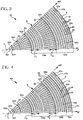
- Figure 3 illustrates a preferred embodiment of the invention, which is a cylindrical ceramic honeycomb structure 40 wherein all of the cells defined by the interconnected web walls are radial cells 44.
- the network 5 of ceramic webs includes radial webs 46 of varying lengths, each of which has an outer end 47a that joins the inner edge 10 of the outer skin 9 in a generally orthogonal joint 47b.
- Some of the radial webs 48a extend almost completely the radial distance between the centroid C of the structure 40 and the outer skin 9, while other radial webs 48b extend only through a peripheral section of the structure 40.
- all of the radial webs 46 in this embodiment join with the inner edge 10 of the outer skin 9 in the generally orthogonal joint 47b as previously described.
- the network 5 of webs in the structure 40 further includes a plurality of tangential webs 49 that are concentrically disposed around the centroid C and are mutually parallel along an axial length thereof.
- the radial cells 44 are defined between the radial webs 46 and tangential webs 49 wherein the radially extending walls are defined by the radial webs 46 and the tangentially extending walls are defined by the tangential webs 49.
- the number of radial webs 46 is reduced along selected points 50a through 50f known as "transition zones" along the radius of the structure 40. At these transition zones 50a-50f, the number of radial webs 46 is reduced by 1 ⁇ 2, 1/3, or 1 ⁇ 4, etc. Reduction by 1 ⁇ 2 is preferred and is illustrated in Figures 3 and 4 .
- the transition zone at any one of the selected points 50a-50f is defined by the particular tangential wall 49 that intersects with the selected point in the radius.
- the distance between the tangential webs 49 may change in the direction between the centroid C and the outer skin 9. For example, compare D 1 and D 2 , illustrating that the spacing decreases the closer in radial proximity to the skin 9.
- Such closer spacing of the webs 49 compensates for the tangential widening of the cells 33 caused by the angular divergence between adjacent radial webs 46 as they radiate from the centroid C of the structure 40.
- the cross sectional area of at least some of the radially spaced cells 44 may be made to have substantially uniform cross sectional area.
- a reinforced tangential web 52 may be provided which is substantially thicker than the balance of the tangential webs 49.
- the thickness of each reinforced tangential web 52 should be on the order of 0.203 mm (8.0 mils).
- the thickening of the tangential webs 52 advantageously reduces stresses generated on these walls from forces resulting from the presence of lesser numbers of radial webs 46 on its interior side towards the centroid C as on its exterior side toward the outer skin 9.
- each of the interior web intersections may include a fillet.
- the fillet radius is preferably about 0.127 mm (5.0 mils), but will significantly vary with other configurations.
- fillets may be included only at some or all of the transition zones 50a-50f between the radial webs 46 and the transition webs 52 to further reinforce and strengthen these zones.
- Figure 4 illustrates an octant section of an alternate embodiment of the invention.
- This embodiment is in all respects identical to the embodiment described with respect to Figure 3 , with the exception that every other radial web 46 has been removed from the network 5 in the most peripheral zone 54c, such that the resulting radial cells 54 are twice as large as the balance of the radial cells 44 in the network 5.
- the number of radial webs 46 actually decreases in the radial direction toward the outer skin 9, in contrast to the Figure 3 embodiment wherein the number of radial webs 46 increases at all points along the radius toward the outer skin 9.
- the invention also encompass ceramic honeycomb structures having other curved shapes, such as the structure 70 having an elliptical cross-section illustrated in Figure 5 (two quadrants shown).
- Structure 70 has a central axis A that intersects with the two foci (not shown) of the elliptical shape, and all of the radial webs 46 diverge from one another and extend away from the central axis A as shown.
- the embodiment 70 illustrated in Figure 5 includes radial webs 46 of varying lengths and the number of cells 44 is reduced at least a certain points in the radial direction.
- radial web 48a extends the entire radial length of the network 5 of webs, while radial web 48b extends along only the peripheral group of webs 54b.
- Tangential webs 49 are further provided, and the tangential webs 50a, 50b defining transition zones are rendered stronger by providing an increased thickness therein.
- the transition webs 50a, 50b may be also made stronger, for instance, by web tapering at the junction of the transition web and the radial web, i.e., tapering the radial wall to include a larger taper approaching the transition web, or by providing fillets at the radial web, transition web intersection, for example.
- the embodiment 70 of the invention does not have the uniform compressive strength characteristics 360° around its perimeter that the previously described embodiments 40, 60 do. Nonetheless, most of the advantages associated with the invention are present in the third embodiment 70 of the invention.
- the cross section of the honeycomb structure embodying the invention may also be oval or "race track” shaped. It should be noted that a honeycomb structure having a "race track” cross section would have similar uniform strength 360° around its periphery as the embodiments 40, 60 previously . described, as all of the radial webs 46 could join with the inner edge 10 of the outer skin in a substantially orthogonal orientation.
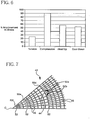
- Figure 6 is a bar graph illustrating the percentage improvement in stress of the Figure 3 embodiment 40 over the ceramic substrate 1 illustrated in Figures 1A and 1B .
- the average stresses generated as a result of radial tension, radial compression, down-heat up load, and cool down thermal loading are substantially less (are improved) for the inventive ceramic honeycomb illustrated in Figure 3 versus the prior art illustrated in Figures 1A and 1B .
- the invention exhibited a large average decrease in maximum stress over its 360° circumference, with greater than 20% improvement in all categories.
- the stresses generated within the inventive structures is highly uniform between 0 degrees and 45 degrees.
- the peripheral stresses generated within the prior art structure 1 oscillate around the circumference of the structure 1 to values that are multiples higher. These higher stress points correspond to the oblique orientation of some of the web walls in the vicinity of 45 degrees and multiples thereof. These indicate weak points in the prior art structure 1 that may be more prone to cracking or failure during either manufacture or operation.
- the inventive structures eliminate such oscillations in the stress patterns.
- Figure 7 is a finite element analysis of the intersection of an octant of the ceramic honeycomb structure 40 illustrating how the stresses are maximized at the transition zones within the structure 42 where the number or radial webs 46 is reduced (e.g., halved).
- stress is maximized at the points where radial webs 46 join the transition tangential webs (e.g., 50d-50f), thereby applying forces to the webs at these points (52a, 52b).
- peripheral webs 50a-50f are rendered stronger by making them thicker than the normal (non-transitional) tangential webs 49 (although other strengthening techniques, such as fillets, or tapered radial webs could be optionally additionally employed). These walls 52 may be 2 or more times as thick as the non-transitional webs 49.
Landscapes
- Chemical & Material Sciences (AREA)
- Engineering & Computer Science (AREA)
- Geometry (AREA)
- Physics & Mathematics (AREA)
- Ceramic Engineering (AREA)
- Chemical Kinetics & Catalysis (AREA)
- Structural Engineering (AREA)
- Materials Engineering (AREA)
- Organic Chemistry (AREA)
- Manufacturing & Machinery (AREA)
- Combustion & Propulsion (AREA)
- Mechanical Engineering (AREA)
- General Engineering & Computer Science (AREA)
- Filtering Materials (AREA)
- Catalysts (AREA)
- Filtering Of Dispersed Particles In Gases (AREA)
- Exhaust Gas After Treatment (AREA)
- Press-Shaping Or Shaping Using Conveyers (AREA)
Applications Claiming Priority (2)
| Application Number | Priority Date | Filing Date | Title |
|---|---|---|---|
| US11/394,694 US7575793B2 (en) | 2006-03-31 | 2006-03-31 | Radial cell ceramic honeycomb structure |
| PCT/US2007/007309 WO2007126712A1 (en) | 2006-03-31 | 2007-03-23 | Radial cell ceramic honeycomb structure |
Publications (2)
| Publication Number | Publication Date |
|---|---|
| EP2007498A1 EP2007498A1 (en) | 2008-12-31 |
| EP2007498B1 true EP2007498B1 (en) | 2018-10-17 |
Family
ID=38318487
Family Applications (1)
| Application Number | Title | Priority Date | Filing Date |
|---|---|---|---|
| EP07753899.9A Ceased EP2007498B1 (en) | 2006-03-31 | 2007-03-23 | Radial cell ceramic honeycomb structure |
Country Status (5)
| Country | Link |
|---|---|
| US (1) | US7575793B2 (https=) |
| EP (1) | EP2007498B1 (https=) |
| JP (1) | JP5049337B2 (https=) |
| CN (1) | CN101437600A (https=) |
| WO (1) | WO2007126712A1 (https=) |
Families Citing this family (41)
| Publication number | Priority date | Publication date | Assignee | Title |
|---|---|---|---|---|
| DE102006035053A1 (de) * | 2005-09-20 | 2007-03-22 | Robert Bosch Gmbh | Filterelement und Rußfilter mit geometrisch ähnlichen Kanälen |
| DE102006045164A1 (de) * | 2006-09-25 | 2008-04-03 | Robert Bosch Gmbh | Filterelement, insbesondere zur Filterung von Abgasen einer Brennkraftmaschine |
| US20090217524A1 (en) * | 2008-02-28 | 2009-09-03 | Jeffrey John Domey | Method and apparatus for manufacturing a honeycomb article |
| FR2957267B1 (fr) * | 2010-03-10 | 2012-04-27 | Technologies Avancees Et Membranes Ind | Nouvelle geometrie de support et membrane de filtration |
| WO2011114511A1 (ja) * | 2010-03-19 | 2011-09-22 | イビデン株式会社 | ハニカム構造体 |
| EP2368619B1 (en) * | 2010-03-26 | 2014-06-25 | Imerys | Ceramic honeycomb structures |
| JP5771541B2 (ja) * | 2012-01-27 | 2015-09-02 | 株式会社デンソー | ハニカム構造体 |
| JP5892911B2 (ja) | 2012-01-27 | 2016-03-23 | 株式会社デンソー | ハニカム構造体 |
| JP5892910B2 (ja) | 2012-01-27 | 2016-03-23 | 株式会社デンソー | ハニカム構造体 |
| US9475245B2 (en) * | 2012-05-08 | 2016-10-25 | Corning Incorporated | Honeycomb extrusion apparatus and methods |
| EP2698190B1 (en) * | 2012-08-13 | 2018-06-27 | NGK Insulators, Ltd. | Plugged Honeycomb Structure |
| JP5708670B2 (ja) * | 2013-01-18 | 2015-04-30 | 株式会社デンソー | ハニカム構造体 |
| US10189017B2 (en) | 2013-01-25 | 2019-01-29 | Yara International Asa | Honeycomb monolith structure |
| JP5958567B2 (ja) * | 2014-03-05 | 2016-08-02 | 株式会社デンソー | ハニカム構造体 |
| JP6142830B2 (ja) | 2014-03-20 | 2017-06-07 | 株式会社デンソー | ハニカム構造体及びハニカム構造体の設計方法 |
| JP6174509B2 (ja) * | 2014-03-31 | 2017-08-02 | 日本碍子株式会社 | ハニカム構造体 |
| NO20140934A1 (no) * | 2014-07-23 | 2016-01-25 | Yara Int Asa | Bikake-monolittstruktur |
| JP6314783B2 (ja) * | 2014-10-10 | 2018-04-25 | 株式会社デンソー | 排ガス浄化フィルタ |
| JP6568378B2 (ja) * | 2015-04-06 | 2019-08-28 | イビデン株式会社 | 通電加熱式触媒 |
| EP3344365B1 (en) | 2015-08-31 | 2023-11-01 | Corning Incorporated | Ceramic honeycomb bodies, honeycomb extrusion dies, and methods of making ceramic honeycomb bodies |
| JP6530680B2 (ja) * | 2015-09-02 | 2019-06-12 | 日本碍子株式会社 | 目封止ハニカム構造体、及び目封止ハニカムセグメント |
| JP2017053283A (ja) * | 2015-09-10 | 2017-03-16 | 本田技研工業株式会社 | 内燃機関の排気浄化装置 |
| JP6782571B2 (ja) * | 2016-07-14 | 2020-11-11 | イビデン株式会社 | ハニカム構造体 |
| US10175003B2 (en) | 2017-02-28 | 2019-01-08 | General Electric Company | Additively manufactured heat exchanger |
| MX2020002230A (es) * | 2017-08-28 | 2020-07-20 | Corning Inc | Cuerpo de panal con estructura de panal radial con componente estructural de transicion y troquel de extrusion del mismo. |
| JP7114886B2 (ja) | 2017-12-07 | 2022-08-09 | 株式会社デンソー | ハニカム構造体 |
| WO2019125830A1 (en) | 2017-12-22 | 2019-06-27 | Corning Incorporated | Extrusion dies |
| CN110006274A (zh) * | 2018-01-04 | 2019-07-12 | 日本碍子株式会社 | 热交换部件及热交换器 |
| JP7166246B2 (ja) * | 2018-01-05 | 2022-11-07 | 日本碍子株式会社 | 熱交換部材、熱交換器及び浄化手段付き熱交換器 |
| US10792653B2 (en) * | 2018-02-06 | 2020-10-06 | Denso International America, Inc. | Emissions control substrate |
| JP7061491B2 (ja) * | 2018-03-27 | 2022-04-28 | 日本碍子株式会社 | ハニカム構造体 |
| EP3775509B1 (en) * | 2018-03-29 | 2023-09-27 | Corning Incorporated | Honeycomb body with varying cell densities and extrusion die for the manufacture thereof |
| JP7184629B2 (ja) * | 2018-03-30 | 2022-12-06 | 日本碍子株式会社 | 熱交換器 |
| CN114471151A (zh) * | 2018-07-18 | 2022-05-13 | 深圳大学 | 催化炉 |
| JP7206092B2 (ja) * | 2018-10-23 | 2023-01-17 | 日本碍子株式会社 | 加熱装置及びその製造方法、並びにシステム |
| DE102019107386A1 (de) * | 2019-03-22 | 2020-09-24 | Eberspächer Exhaust Technology GmbH & Co. KG | Substrat für eine Abgasbehandlungseinheit |
| US11215096B2 (en) | 2019-08-21 | 2022-01-04 | Corning Incorporated | Systems and methods for uniformly heating a honeycomb body |
| US12418962B2 (en) * | 2019-09-16 | 2025-09-16 | Corning Incorporated | Systems and methods for electrically heating a catalyst with a honeycomb body having radial walls |
| US11920874B2 (en) * | 2021-02-09 | 2024-03-05 | Ngk Insulators, Ltd. | Heat exchange member, heat exchanger and heat conductive member |
| JP2024131752A (ja) * | 2023-03-16 | 2024-09-30 | 日本碍子株式会社 | ハニカム構造体及び熱交換器 |
| US12259194B2 (en) | 2023-07-10 | 2025-03-25 | General Electric Company | Thermal management system |
Citations (1)
| Publication number | Priority date | Publication date | Assignee | Title |
|---|---|---|---|---|
| JPS54110189A (en) * | 1978-02-17 | 1979-08-29 | Ngk Insulators Ltd | Ceramic honeycomb structure |
Family Cites Families (19)
| Publication number | Priority date | Publication date | Assignee | Title |
|---|---|---|---|---|
| US3963504A (en) * | 1972-07-05 | 1976-06-15 | W. R. Grace & Co. | Porous ceramic structure |
| US4054702A (en) * | 1976-03-05 | 1977-10-18 | W. R. Grace & Co. | Monolith design |
| JPS5546338A (en) * | 1978-09-28 | 1980-04-01 | Ngk Insulators Ltd | Heat and shock resistant, revolving and heat-regenerating type ceramic heat exchanger body and its manufacturing |
| US4363644A (en) * | 1980-02-04 | 1982-12-14 | Nippon Soken, Inc. | Filter for purifying exhaust gas |
| US4416675A (en) * | 1982-02-22 | 1983-11-22 | Corning Glass Works | High capacity solid particulate filter apparatus |
| EP0225402A1 (en) | 1985-11-05 | 1987-06-16 | Nippondenso Co., Ltd. | Porous ceramic structure |
| US4877670A (en) * | 1985-12-27 | 1989-10-31 | Ngk Insulators, Ltd. | Cordierite honeycomb structural body and method of producing the same |
| DE3809490C1 (https=) | 1988-03-22 | 1989-05-11 | Sueddeutsche Kuehlerfabrik Julius Fr. Behr Gmbh & Co Kg, 7000 Stuttgart, De | |
| JP2505261B2 (ja) * | 1988-09-29 | 1996-06-05 | 日本碍子株式会社 | セラミック熱交換体およびその製造法 |
| FR2741822B1 (fr) * | 1995-12-05 | 1998-02-20 | Tami Ind | Element tubulaire inorganique de filtration comportant des canaux de section non circulaire presentant des profils optimises |
| US5641332A (en) * | 1995-12-20 | 1997-06-24 | Corning Incorporated | Filtraion device with variable thickness walls |
| EP0854123B1 (en) * | 1996-08-07 | 2006-04-05 | Denso Corporation | Ceramic honeycomb structure and method of production thereof |
| DE19704144A1 (de) * | 1997-02-04 | 1998-08-06 | Emitec Emissionstechnologie | Extrudierter Wabenkörper, insbesondere Katalysator-Trägerkörper, mit verstärkter Wandstruktur |
| JP4159155B2 (ja) * | 1998-01-22 | 2008-10-01 | 株式会社日本自動車部品総合研究所 | セラミックハニカム構造体および押出金型 |
| FR2785831B1 (fr) | 1998-11-18 | 2001-11-23 | Orelis | Support monolithe poreux d'un element de filtration et element de filtration |
| US6508852B1 (en) * | 2000-10-13 | 2003-01-21 | Corning Incorporated | Honeycomb particulate filters |
| US7112050B2 (en) * | 2003-06-26 | 2006-09-26 | Corning Incorporated | Extrusion die for making a double-skin honeycomb substrate |
| US7238217B2 (en) * | 2004-04-23 | 2007-07-03 | Corning Incorporated | Diesel engine exhaust filters |
| DE102006035053A1 (de) | 2005-09-20 | 2007-03-22 | Robert Bosch Gmbh | Filterelement und Rußfilter mit geometrisch ähnlichen Kanälen |
-
2006
- 2006-03-31 US US11/394,694 patent/US7575793B2/en not_active Expired - Fee Related
-
2007
- 2007-03-23 EP EP07753899.9A patent/EP2007498B1/en not_active Ceased
- 2007-03-23 JP JP2009502899A patent/JP5049337B2/ja not_active Expired - Fee Related
- 2007-03-23 WO PCT/US2007/007309 patent/WO2007126712A1/en not_active Ceased
- 2007-03-23 CN CNA2007800160422A patent/CN101437600A/zh active Pending
Patent Citations (1)
| Publication number | Priority date | Publication date | Assignee | Title |
|---|---|---|---|---|
| JPS54110189A (en) * | 1978-02-17 | 1979-08-29 | Ngk Insulators Ltd | Ceramic honeycomb structure |
Non-Patent Citations (1)
| Title |
|---|
| DATABASE WPI Week 197941, Derwent World Patents Index; AN 1979-74038B * |
Also Published As
| Publication number | Publication date |
|---|---|
| JP2009532605A (ja) | 2009-09-10 |
| US20070231533A1 (en) | 2007-10-04 |
| EP2007498A1 (en) | 2008-12-31 |
| CN101437600A (zh) | 2009-05-20 |
| WO2007126712A1 (en) | 2007-11-08 |
| JP5049337B2 (ja) | 2012-10-17 |
| US7575793B2 (en) | 2009-08-18 |
Similar Documents
| Publication | Publication Date | Title |
|---|---|---|
| EP2007498B1 (en) | Radial cell ceramic honeycomb structure | |
| US7316722B2 (en) | Honeycomb structure | |
| KR100595758B1 (ko) | 하니컴 구조체 및 그 제조 방법 | |
| EP1840347B1 (en) | Honeycomb structure | |
| KR100884518B1 (ko) | 허니컴 구조체 및 그 제조 방법 | |
| JP4282941B2 (ja) | ハニカム構造体及びその製造方法、並びにそれを使用した触媒体 | |
| US8071197B2 (en) | Assembled honeycomb | |
| KR100593275B1 (ko) | 하니컴 구조체 | |
| US8236084B2 (en) | Ceramic radial wall flow particulate filter | |
| US8999481B2 (en) | Ceramic honeycomb filter with enhanced thermal shock resistance | |
| WO2001093984A1 (en) | Honeycomb structure and honeycomb filter, and method of producing them | |
| KR20130135929A (ko) | 밀봉된 하니컴 구조체 | |
| EP1974791A1 (en) | Honeycomb structure and production method thereof | |
| EP2145661B1 (en) | Plugged honeycomb structure | |
| JP4373177B2 (ja) | ハニカム構造体、その製造方法及びキャニング構造体 | |
| JP7061491B2 (ja) | ハニカム構造体 | |
| JP5484571B2 (ja) | マーク付けされたハニカム構造 | |
| JP7066831B2 (ja) | 移行構造要素を有する半径方向のハニカム構造体を備えたハニカム体および該ハニカム体用の押出ダイ | |
| JP2012532742A5 (https=) | ||
| JP2005144250A (ja) | ハニカム構造体 | |
| US8137637B2 (en) | Particulate filter and method of making | |
| US7597948B2 (en) | Ceramic honeycomb structure having reduced stress web-skin joints | |
| JP2017185484A (ja) | 目封止ハニカム構造体 | |
| JP2008023439A (ja) | ハニカム構造体 |
Legal Events
| Date | Code | Title | Description |
|---|---|---|---|
| PUAI | Public reference made under article 153(3) epc to a published international application that has entered the european phase |
Free format text: ORIGINAL CODE: 0009012 |
|
| 17P | Request for examination filed |
Effective date: 20081030 |
|
| AK | Designated contracting states |
Kind code of ref document: A1 Designated state(s): AT BE BG CH CY CZ DE DK EE ES FI FR GB GR HU IE IS IT LI LT LU LV MC MT NL PL PT RO SE SI SK TR |
|
| AX | Request for extension of the european patent |
Extension state: AL BA HR MK RS |
|
| DAX | Request for extension of the european patent (deleted) | ||
| RBV | Designated contracting states (corrected) |
Designated state(s): DE FR GB |
|
| 17Q | First examination report despatched |
Effective date: 20140918 |
|
| GRAP | Despatch of communication of intention to grant a patent |
Free format text: ORIGINAL CODE: EPIDOSNIGR1 |
|
| INTG | Intention to grant announced |
Effective date: 20180611 |
|
| GRAS | Grant fee paid |
Free format text: ORIGINAL CODE: EPIDOSNIGR3 |
|
| GRAA | (expected) grant |
Free format text: ORIGINAL CODE: 0009210 |
|
| AK | Designated contracting states |
Kind code of ref document: B1 Designated state(s): DE FR GB |
|
| REG | Reference to a national code |
Ref country code: GB Ref legal event code: FG4D |
|
| REG | Reference to a national code |
Ref country code: DE Ref legal event code: R096 Ref document number: 602007056513 Country of ref document: DE |
|
| REG | Reference to a national code |
Ref country code: DE Ref legal event code: R097 Ref document number: 602007056513 Country of ref document: DE |
|
| PLBE | No opposition filed within time limit |
Free format text: ORIGINAL CODE: 0009261 |
|
| STAA | Information on the status of an ep patent application or granted ep patent |
Free format text: STATUS: NO OPPOSITION FILED WITHIN TIME LIMIT |
|
| 26N | No opposition filed |
Effective date: 20190718 |
|
| PGFP | Annual fee paid to national office [announced via postgrant information from national office to epo] |
Ref country code: GB Payment date: 20200228 Year of fee payment: 14 Ref country code: DE Payment date: 20200214 Year of fee payment: 14 |
|
| PGFP | Annual fee paid to national office [announced via postgrant information from national office to epo] |
Ref country code: FR Payment date: 20200219 Year of fee payment: 14 |
|
| REG | Reference to a national code |
Ref country code: DE Ref legal event code: R119 Ref document number: 602007056513 Country of ref document: DE |
|
| GBPC | Gb: european patent ceased through non-payment of renewal fee |
Effective date: 20210323 |
|
| PG25 | Lapsed in a contracting state [announced via postgrant information from national office to epo] |
Ref country code: GB Free format text: LAPSE BECAUSE OF NON-PAYMENT OF DUE FEES Effective date: 20210323 Ref country code: FR Free format text: LAPSE BECAUSE OF NON-PAYMENT OF DUE FEES Effective date: 20210331 Ref country code: DE Free format text: LAPSE BECAUSE OF NON-PAYMENT OF DUE FEES Effective date: 20211001 |