EP2006453B1 - Cadre d'étayage en U - Google Patents
Cadre d'étayage en U Download PDFInfo
- Publication number
- EP2006453B1 EP2006453B1 EP08158540.8A EP08158540A EP2006453B1 EP 2006453 B1 EP2006453 B1 EP 2006453B1 EP 08158540 A EP08158540 A EP 08158540A EP 2006453 B1 EP2006453 B1 EP 2006453B1
- Authority
- EP
- European Patent Office
- Prior art keywords
- strut
- expanding
- shoring
- guide
- additional
- Prior art date
- Legal status (The legal status is an assumption and is not a legal conclusion. Google has not performed a legal analysis and makes no representation as to the accuracy of the status listed.)
- Not-in-force
Links
Images


Classifications
-
- E—FIXED CONSTRUCTIONS
- E02—HYDRAULIC ENGINEERING; FOUNDATIONS; SOIL SHIFTING
- E02D—FOUNDATIONS; EXCAVATIONS; EMBANKMENTS; UNDERGROUND OR UNDERWATER STRUCTURES
- E02D17/00—Excavations; Bordering of excavations; Making embankments
- E02D17/06—Foundation trenches ditches or narrow shafts
- E02D17/08—Bordering or stiffening the sides of ditches trenches or narrow shafts for foundations
- E02D17/083—Shoring struts
-
- E—FIXED CONSTRUCTIONS
- E02—HYDRAULIC ENGINEERING; FOUNDATIONS; SOIL SHIFTING
- E02D—FOUNDATIONS; EXCAVATIONS; EMBANKMENTS; UNDERGROUND OR UNDERWATER STRUCTURES
- E02D17/00—Excavations; Bordering of excavations; Making embankments
- E02D17/06—Foundation trenches ditches or narrow shafts
- E02D17/08—Bordering or stiffening the sides of ditches trenches or narrow shafts for foundations
- E02D17/086—Travelling trench shores
Definitions
- the invention relates to a spreading strut for forming a Sp Dreckhornens for shoring devices according to the preamble of claim 1 and with this spreading strut formed Sp Schwarzrahmen and shoring devices which have such Sp Schwarzrahmen.
- Grabenverbauvoriquesen usually have shoring, which consist of two opposing, large-scale Verbauplatten, which support the trench walls. Such bogies can either be installed individually or strung together. In adjoining shingles the edges of the shoring are usually performed in opposing columns. Between the supports bending rigid expansion frame are arranged in height displaceable. For this purpose, the supports have horizontally extending linear guides.
- the supports with the vertical linear guides are usually integrated in the shoring panels. On each side edge of a Verbauplatte such a linear guide is arranged.
- the expansion frames are based on several, a vertical distance from each other having support points relative to the linear guides.
- the support points are usually formed by rollers.
- a shoring device with edge-guided shoring panels is for example from the European patent EP 0 619 853 B1 known.
- the Sp lanternrahmen two mutually parallel struts. These struts are connected by vertically extending and at different heights on the linear guide supporting carriage with each other. On each side of the Sp Schwarzrahmens a carriage between an upper and lower Sp Schwarzstrebe is arranged.
- Sp Drettillhornen which have the shape of an inverted U.
- the two lateral legs of the inverted U are formed by the two carriages.
- At the upper end of each carriage one end of the expansion strut is flanged.
- Such a Sp Schwarzrahmen allows a greater installation height of internals, especially pipes, which are installed in the channel, which is supported by the shoring device.
- the object of the invention is to develop a simple and inexpensive Verbauvorraum such that below a Sp Drhyroids a larger installation space remains.
- a connecting strut is attached to the ends of the spreading strut, which extends transversely to the spreading strut and is arranged at the lower end of one of the fastening elements.
- the fastening elements are arranged at the ends of the expansion strut, in each case with the interposition of a connecting strut extending transversely to the expansion strut.
- connection strut extends vertically, wherein the expansion strut extends horizontally.
- the guide member which is usually formed by the carriage, is arranged in a predetermined by the position of the linear guide height. Since the expansion strut now no longer extends directly between the guide members, but offset upwards between the attached to the guide links connecting struts, the clear space below the expansion strut can be significantly increased.
- the spreading strut can be raised, for example, by 1 meter.
- the connecting struts can simply be removed from the ends of the spreading strut and the guide members can be flanged directly to the end of the spreading strut.
- the system according to the invention is therefore extremely variable. It can be carried out either with direct attachment of the guide members at the ends of the spreader strut with normal passage height or when using the connection struts with increased passage height.
- the expansion strut and the connecting strut are usually made of metal profiles, usually made of steel.
- the ends of the expansion strut are bolted or welded to the connecting struts.
- the screw allows variable conversion of the expansion strut according to the invention by removing the connecting struts.
- the fastener may be on the connecting strut a flange plate with through holes for connecting screws.
- the holding element of the guide member may be formed by a complementary flange plate.
- the Spstrestrebenende may have a flange plate which is formed corresponding to that on the connecting strut. So the spreading strut can firstly directly and secondly under embglagung the connection bars according to the invention are screwed to the guide element.
- an additional fastening element can be arranged at the upper end of the connecting strut. For example, if additional sheathing panels must be placed to realize a deeper trench, a head portion can be attached to the additional fastener which holds the additional shoring panels.
- the invention relates to a spreader frame with two guide members, which are connectable to the sliding guide in each case with a linear guide a Verbauvorraum, and with a spreading strut described above.
- a connecting strut is attached to each end of the spreading strut, which extends transversely to the spreading strut and at the lower end of which one of the fastening elements is arranged.
- Fasteners and retaining elements consist - as mentioned - preferably from flange plates with matching hole patterns for passing through fastening screws.
- the guide members of the expansion frame according to the invention are preferably formed by carriages.
- the carriages have vertically spaced-apart rollers, which are intended to unroll on a guide surface of a vertical linear guide of a shoring device.
- the linear guides are either provided on the sides facing each other by separate supports, which respectively support the edges of Verbauplatten, or integrated into the Verbauplatten.
- the guide member may have a retaining body which engages positively in a guide channel of the linear guide. This retaining body transmits tensile forces on the expansion frame and prevents tilting of the lining plate, in which the lower end of the lining plate is pushed towards the trench center.
- the lower end of the connecting strut is secured to the upper end of the guide member to allow an optimal increase in the space below the expansion strut. This extends the Connecting strut from the guide member from vertically upwards.
- the above-mentioned additional fastener at the upper end of the connection strut can cooperate with an additional holding element, which is arranged on a head part.
- the headboard can be inserted in an additional linear guide.
- the additional linear guide can be arranged in practice on an additional Verbauplatte, which serves to increase the Verbaufeldes.
- the invention relates to a shoring device with two opposite, large-scale Verbauplatten on which vertical linear guides are arranged.
- a spreader frame of the type described above is inserted between two mutually opposite linear guides.
- the linear guides are preferably formed by supports connected to the lining plate.
- a support can either receive and support a vertical edge of the lining plate or be fixedly connected to a vertical edge of the lining plate.
- an additional lining plate can be plugged onto the opposite lining plates, which each have an additional linear guide, in which one of the head parts is guided displaceably.
- the head part which is arranged at the upper end of the connecting strut, thus supports the additional Verbauplatte and fixes them vertically above the lower Verbauplatte and aligned with this.
- the in the Fig. 1 Shoring device shown consists of two large Verbauplatten 1,2, which are arranged opposite one another and serve to support the walls of a trench. At the vertical edges of Verbauplatten 1,2 vertical supports 3,4,5,6 are arranged. The supports 3 - 6 are firmly connected to the Verbauplatten 1,2 in the illustrated embodiment. In alternative embodiments of the invention (not shown), the supports are formed separately and have guide channels in which the edges of the Verbauplatten can be supported.
- Each support 3-6 has a linear guide 7-10 in its upper region.
- the linear guides 7-10 have two mutually parallel guide webs 11,12, which form guide surfaces and between which a guide channel is formed.
- On the guide surfaces roll rollers in a known manner.
- In the guide channel engages a retaining body in a known manner.
- the rollers and the retaining body are each arranged on a carriage 13-16, which forms a lateral guide member for the Sp Schwarzrahmen and in conjunction with Fig. 6 will be described below.
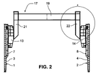
- the in the Fig. 1 and 2 shown shoring device has two identical Sp Schwarzrahmen 17 and 18.
- Each expansion frame 17 and 18 has a two-part expansion strut 19 and 20, respectively.
- a connecting strut 21-24 is attached at the two ends of each spreading strut 19,20 .
- the ends of the spreading struts 19, 20 have flange plates which are screwed to wall sections of the connecting struts 21-24.
- One of the outer wall of the connecting strut 22nd (please refer Fig. 3 ) formed in the lower region flange plate 35 forms the arranged at the end of the expansion strut 19 fastener and is bolted to a complementary flange 36 at the upper end of the carriage 14.
- connection struts 21-24 By the vertically extending connection struts 21-24 ( Fig. 1 ), the clear height below the expansion strut 19,20 is significantly increased. If such a large clearance height is not required, the connecting struts 21-24 can be removed between the ends of the spreading struts 19,20 and the carriage 13-16 and the carriages 13-16 are screwed directly to the ends of the spreading strut 19, 20.
- the device according to the invention is additionally advantageous for larger installation depths.
- the upper, facing the trench wall portion of the outer wall of the connecting strut 22 forms a flange plate 37, which forms an additional fastening means.
- the additional attachment means 37 cooperates with an additional holding means 38 of the head part 26.
- This additional holding means 38 is formed by a flange plate 38 arranged on the head part 26, which lies on the side of the head part 26 facing towards the trench center. All flange plates 35-38 are preferably formed by steel plates, which are part of the steel profiles that make up the respective components.
- the head part 25,26 serves to stabilize additional Verbauplatten 27,28, which are attached to the upper edge of the lower Verbauplatten 1,2.
- the additional Verbauplatten 27,28 have additional linear guides 29,30, which are supported against the head parts 25,26 and are also engaged behind this. In this way, the additional Verbauplatten 27,28 vertically aligned with the lower Verbauplatten 1,2 aligned thereto by means of the head parts 25,26.
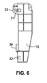
- the Fig. 6 shows one of the carriage 13.
- the carriage 13 has at its upper and lower ends in each case a roller 31,32, the on a guide surface of the linear guide 7-10 ( Fig. 1 ) rolls off.
- the carriage 13 has two retaining bodies 33, 34. These retaining bodies 33, 34 can be inserted into the guide channel of the linear guide 7 - 10 (FIG. Fig. 1 ) are inserted.
- the upper retaining body 33 is formed as a roller.
- the lower retaining body 34 is a short rail of T-shaped cross-section.
Landscapes
- Engineering & Computer Science (AREA)
- Mining & Mineral Resources (AREA)
- Life Sciences & Earth Sciences (AREA)
- General Life Sciences & Earth Sciences (AREA)
- Paleontology (AREA)
- Civil Engineering (AREA)
- General Engineering & Computer Science (AREA)
- Structural Engineering (AREA)
- Support Devices For Sliding Doors (AREA)
- Joining Of Corner Units Of Frames Or Wings (AREA)
- Wing Frames And Configurations (AREA)
- Mirrors, Picture Frames, Photograph Stands, And Related Fastening Devices (AREA)
Claims (14)
- Barre d'étaiement (19, 20) pour un cadre d'étaiement (17, 18) pour dispositifs de blindage, sur les deux extrémités de laquelle est disposé un élément de fixation (35) respectif pour la fixation sur un élément de retenue (36) complémentaire d'un membre de guidage (13-16), caractérisée en ce qu'une barre de raccordement (21-24) respective est fixée sur les extrémités de la barre d'étaiement (19, 20), qui s'étend transversalement à la barre d'étaiement (19, 20) et sur l'extrémité inférieure de laquelle un des éléments de fixation (35) est disposé.
- Barre d'étaiement (19, 20) selon la revendication 1, caractérisée en ce que la barre d'étaiement (19, 20) et la barre de raccordement (21-24) sont formées de profilés métalliques.
- Barre d'étaiement (19, 20) selon la revendication 1 ou 2, caractérisée en ce que les extrémités de la barre d'étaiement (19, 20) sont vissées ou soudées aux barres de raccordement (21-24).
- Barre d'étaiement (19, 20) selon l'une des revendications précédentes, caractérisée en ce que l'élément de fixation est une plaque de bride (35) avec des trous de passage pour les vis de liaison.
- Barre d'étaiement (19, 20) selon l'une des revendications précédentes, caractérisé en ce qu'un élément de fixation supplémentaire (37) est disposé sur l'extrémité supérieure de la barre de raccordement (21-24).
- Cadre d'étaiement (17, 18) comprenant deux membres de guidage (13-16) qui peuvent être reliés pour un guidage par déplacement respectivement à un guidage linéaire (7-10) d'un dispositif de blindage, et comprenant une barre d'étaiement (19, 20) selon l'une des revendications précédentes, caractérisé en ce qu'une barre de raccordement (21-24) est fixée sur chaque extrémité de la barre d'étaiement (19, 20), qui s'étend transversalement à la barre d'étaiement (19, 20) et sur l'extrémité inférieure de laquelle un des éléments de fixation (35) est disposé.
- Cadre d'étaiement (17, 18) selon la revendication 6, caractérisé en ce que le membre de guidage est un chariot de roulement (13-16) avec des galets de roulement (31, 32) disposés à distance l'un de l'autre qui sont prévus pour rouler sur une surface de guidage d'un guidage linéaire (7-10) vertical d'un dispositif de blindage.
- Cadre d'étaiement (17, 18) selon la revendication 6 ou 7, caractérisé en ce que le membre de guidage présente au moins un corps de retenue (33, 34) qui se met en prise par adhérence des formes dans un canal de guidage du guidage linéaire (7-10).
- Cadre d'étaiement (17, 18) selon l'une des revendications 6 à 8, caractérisé en ce que l'extrémité inférieure de la barre de raccordement (21-24) est fixée sur l'extrémité supérieure du membre de guidage (13-16).
- Cadre d'étaiement (17, 18) selon l'une des revendications 6 à 9, caractérisé en ce que la barre de raccordement (21-24) s'étend verticalement vers le haut depuis le membre de guidage (13-16).
- Cadre d'étaiement (17, 18) selon l'une des revendications 6 à 10, caractérisé en ce que l'élément de fixation supplémentaire (37) peut être relié sur l'extrémité supérieure de la barre de raccordement (21-24) avec un élément de retenue supplémentaire (38) d'une partie de tête (25, 26), qui peut être inséré dans un guidage linéaire (29, 30) supplémentaire.
- Dispositif de blindage comprenant deux plaques de blindage (1, 2) de grande surface, opposées l'une à l'autre, sur lesquelles des guidages linéaires (7-10) verticaux sont disposés, caractérisé en ce qu'un cadre d'étaiement (17, 18) selon l'une des revendications 6 à 11 est disposé entre deux guidages linéaires (7, 8 ; 9, 10) opposés l'un à l'autre.
- Dispositif de blindage selon la revendication 12, caractérisé en ce que chaque guidage linéaire (7-10) est disposé sur un étai relié à la plaque de blindage (1, 2).
- Dispositif de blindage selon la revendication 12 ou 13, caractérisé en ce que des plaques de blindage (27, 28) supplémentaires sont placées sur les plaques de blindage (1, 2) opposées l'une à l'autre, lesquelles présentent respectivement au moins un guidage linéaire (29, 30) supplémentaire dans lequel l'une des parties de tête (25, 26) est guidée en pouvant être déplacée.
Priority Applications (2)
| Application Number | Priority Date | Filing Date | Title |
|---|---|---|---|
| SI200831023T SI2006453T1 (sl) | 2007-06-21 | 2008-06-19 | Nosilni okvir v obliki ÄŤrke U |
| PL08158540T PL2006453T3 (pl) | 2007-06-21 | 2008-06-19 | U-kształtna rama rozporowa |
Applications Claiming Priority (1)
| Application Number | Priority Date | Filing Date | Title |
|---|---|---|---|
| DE102007029048A DE102007029048A1 (de) | 2007-06-21 | 2007-06-21 | U-Spreizrahmen |
Publications (3)
| Publication Number | Publication Date |
|---|---|
| EP2006453A2 EP2006453A2 (fr) | 2008-12-24 |
| EP2006453A3 EP2006453A3 (fr) | 2013-01-16 |
| EP2006453B1 true EP2006453B1 (fr) | 2013-08-14 |
Family
ID=39591539
Family Applications (1)
| Application Number | Title | Priority Date | Filing Date |
|---|---|---|---|
| EP08158540.8A Not-in-force EP2006453B1 (fr) | 2007-06-21 | 2008-06-19 | Cadre d'étayage en U |
Country Status (8)
| Country | Link |
|---|---|
| EP (1) | EP2006453B1 (fr) |
| DE (1) | DE102007029048A1 (fr) |
| DK (1) | DK2006453T3 (fr) |
| ES (1) | ES2431146T3 (fr) |
| HR (1) | HRP20131062T1 (fr) |
| PL (1) | PL2006453T3 (fr) |
| PT (1) | PT2006453E (fr) |
| SI (1) | SI2006453T1 (fr) |
Families Citing this family (6)
| Publication number | Priority date | Publication date | Assignee | Title |
|---|---|---|---|---|
| DE102009009406B4 (de) | 2009-02-18 | 2011-05-12 | Hess, Wilhelm | Spreizrahmen |
| DE202010000447U1 (de) * | 2010-03-23 | 2010-06-02 | Thyssenkrupp Bauservice Gmbh | Verbauvorrichtung für den Verbau von Gräben |
| DK177493B1 (da) * | 2012-01-30 | 2013-07-15 | Stenger Aps | Gravekasse med plane sider |
| CN111022763A (zh) * | 2020-01-02 | 2020-04-17 | 成都九执星科技有限公司 | 一种道路埋管组件及埋管方法和埋管组件的生产装置及方法 |
| CN113322979B (zh) * | 2021-06-10 | 2022-05-17 | 北京市政建设集团有限责任公司 | 一种组合型预制装配式顶管工作井的新型支护结构 |
| CN114293565B (zh) * | 2021-11-29 | 2023-06-20 | 广州宏途设备工程有限公司 | 一种高可靠性的基坑支护结构 |
Family Cites Families (4)
| Publication number | Priority date | Publication date | Assignee | Title |
|---|---|---|---|---|
| EP0238783B1 (fr) * | 1986-02-27 | 1990-05-02 | Friedr. Ischebeck GmbH | Unité de blindage de tranchée |
| DE4226405A1 (de) | 1992-08-10 | 1994-02-17 | Emunds & Staudinger Gmbh & Co | Verbauvorrichtung |
| DE4230860A1 (de) | 1992-09-15 | 1994-03-17 | Wilhelm Hes | Verbauvorrichtung |
| DE202004011513U1 (de) * | 2004-07-22 | 2004-10-07 | Emunds & Staudinger Gmbh | Spreizrahmen für eine Graben-Verbauvorrichtung |
-
2007
- 2007-06-21 DE DE102007029048A patent/DE102007029048A1/de not_active Withdrawn
-
2008
- 2008-06-19 PT PT81585408T patent/PT2006453E/pt unknown
- 2008-06-19 ES ES08158540T patent/ES2431146T3/es active Active
- 2008-06-19 SI SI200831023T patent/SI2006453T1/sl unknown
- 2008-06-19 PL PL08158540T patent/PL2006453T3/pl unknown
- 2008-06-19 EP EP08158540.8A patent/EP2006453B1/fr not_active Not-in-force
- 2008-06-19 DK DK08158540.8T patent/DK2006453T3/da active
-
2013
- 2013-11-07 HR HRP20131062AT patent/HRP20131062T1/hr unknown
Also Published As
| Publication number | Publication date |
|---|---|
| ES2431146T3 (es) | 2013-11-25 |
| EP2006453A3 (fr) | 2013-01-16 |
| PL2006453T3 (pl) | 2013-12-31 |
| DK2006453T3 (da) | 2013-11-04 |
| HRP20131062T1 (hr) | 2014-01-17 |
| SI2006453T1 (sl) | 2013-11-29 |
| PT2006453E (pt) | 2013-09-24 |
| DE102007029048A1 (de) | 2008-12-24 |
| EP2006453A2 (fr) | 2008-12-24 |
Similar Documents
| Publication | Publication Date | Title |
|---|---|---|
| EP2006453B1 (fr) | Cadre d'étayage en U | |
| WO1994003683A1 (fr) | Dispositif de coffrage | |
| EP2813783A1 (fr) | Support pour soutenir des panneaux solaires sur un toit plat | |
| WO1994006972A1 (fr) | Dispositif de blindage | |
| DE202009016353U1 (de) | Traganordnung für eine Solaranlage | |
| EP1544377B1 (fr) | Element de coffrage pour murs courbes | |
| DE102009025050B3 (de) | Verbaubox zum Verbau von Gräben | |
| DE102009009406B4 (de) | Spreizrahmen | |
| DE2757450A1 (de) | Betonschalung | |
| EP2847136B1 (fr) | Système de fixation d'un aérateur à bande | |
| EP1704293A1 (fr) | Verrou transversal pour coffrage rond en beton et coffrage rond en beton | |
| DE202006009860U1 (de) | Aussteifungsstruktur und Befestigungselement zur Aussteifung einer Stützen aufweisenden Unterstellung einer Deckenschalung | |
| WO2021052738A1 (fr) | Guide intermédiaire de cage sur une cage de laminoir verticale d'un train de laminoirs, et procédé de guidage du produit laminé à l'aide du guide intermédiaire de cage | |
| DE19703811C2 (de) | Strangführung, insbesondere für eine Brammen-Stranggießanlage | |
| EP0393448B1 (fr) | Equipement d'étançonnage pour l'étrésillonnement de tranchées | |
| WO1984000572A1 (fr) | Dispositif de blindage | |
| DE4322336A1 (de) | Verbauvorrichtung | |
| EP0678629B1 (fr) | Dispositif d'étaiement | |
| DE102005009333B4 (de) | Pressengestell | |
| WO2013186244A1 (fr) | Dispositif de montage | |
| DE102009001275B4 (de) | Regalsystem | |
| DE202008007955U1 (de) | Anordnung zum Verbinden zweier gleichartiger Laufschienen | |
| EP3719237B1 (fr) | Support de coffrage, dispositif de support de coffrage et coffrage de plafond | |
| DE2516418A1 (de) | Schalung fuer isolierfuge o.dgl. zwischenraum | |
| DE2150950C3 (de) | Kupplung fur Betonschalungselemente |
Legal Events
| Date | Code | Title | Description |
|---|---|---|---|
| PUAI | Public reference made under article 153(3) epc to a published international application that has entered the european phase |
Free format text: ORIGINAL CODE: 0009012 |
|
| AK | Designated contracting states |
Kind code of ref document: A2 Designated state(s): AT BE BG CH CY CZ DE DK EE ES FI FR GB GR HR HU IE IS IT LI LT LU LV MC MT NL NO PL PT RO SE SI SK TR |
|
| AX | Request for extension of the european patent |
Extension state: AL BA MK RS |
|
| PUAL | Search report despatched |
Free format text: ORIGINAL CODE: 0009013 |
|
| AK | Designated contracting states |
Kind code of ref document: A3 Designated state(s): AT BE BG CH CY CZ DE DK EE ES FI FR GB GR HR HU IE IS IT LI LT LU LV MC MT NL NO PL PT RO SE SI SK TR |
|
| AX | Request for extension of the european patent |
Extension state: AL BA MK RS |
|
| RIC1 | Information provided on ipc code assigned before grant |
Ipc: E02D 17/08 20060101AFI20121210BHEP |
|
| 17P | Request for examination filed |
Effective date: 20130108 |
|
| GRAP | Despatch of communication of intention to grant a patent |
Free format text: ORIGINAL CODE: EPIDOSNIGR1 |
|
| GRAS | Grant fee paid |
Free format text: ORIGINAL CODE: EPIDOSNIGR3 |
|
| GRAA | (expected) grant |
Free format text: ORIGINAL CODE: 0009210 |
|
| AK | Designated contracting states |
Kind code of ref document: B1 Designated state(s): AT BE BG CH CY CZ DE DK EE ES FI FR GB GR HR HU IE IS IT LI LT LU LV MC MT NL NO PL PT RO SE SI SK TR |
|
| REG | Reference to a national code |
Ref country code: GB Ref legal event code: FG4D Free format text: NOT ENGLISH |
|
| REG | Reference to a national code |
Ref country code: AT Ref legal event code: REF Ref document number: 626973 Country of ref document: AT Kind code of ref document: T Effective date: 20130815 Ref country code: CH Ref legal event code: EP |
|
| AKX | Designation fees paid |
Designated state(s): AT BE BG CH CY CZ DE DK EE ES FI FR GB GR HR HU IE IS IT LI LT LU LV MC MT NL NO PL PT RO SE SI SK TR |
|
| REG | Reference to a national code |
Ref country code: PT Ref legal event code: SC4A Free format text: AVAILABILITY OF NATIONAL TRANSLATION Effective date: 20130917 |
|
| REG | Reference to a national code |
Ref country code: IE Ref legal event code: FG4D Free format text: LANGUAGE OF EP DOCUMENT: GERMAN |
|
| REG | Reference to a national code |
Ref country code: RO Ref legal event code: EPE |
|
| REG | Reference to a national code |
Ref country code: DE Ref legal event code: R096 Ref document number: 502008010473 Country of ref document: DE Effective date: 20131010 |
|
| REG | Reference to a national code |
Ref country code: CH Ref legal event code: NV Representative=s name: MICHELI AND CIE SA, CH |
|
| REG | Reference to a national code |
Ref country code: DK Ref legal event code: T3 Effective date: 20131031 Ref country code: DK Ref legal event code: T3 |
|
| REG | Reference to a national code |
Ref country code: HR Ref legal event code: TUEP Ref document number: P20131062 Country of ref document: HR |
|
| REG | Reference to a national code |
Ref country code: NO Ref legal event code: T2 Effective date: 20130814 Ref country code: ES Ref legal event code: FG2A Ref document number: 2431146 Country of ref document: ES Kind code of ref document: T3 Effective date: 20131125 |
|
| REG | Reference to a national code |
Ref country code: NL Ref legal event code: T3 |
|
| REG | Reference to a national code |
Ref country code: SE Ref legal event code: TRGR |
|
| REG | Reference to a national code |
Ref country code: PL Ref legal event code: T3 |
|
| REG | Reference to a national code |
Ref country code: SK Ref legal event code: T3 Ref document number: E 15101 Country of ref document: SK |
|
| REG | Reference to a national code |
Ref country code: HR Ref legal event code: T1PR Ref document number: P20131062 Country of ref document: HR |
|
| REG | Reference to a national code |
Ref country code: LT Ref legal event code: MG4D |
|
| PG25 | Lapsed in a contracting state [announced via postgrant information from national office to epo] |
Ref country code: IS Free format text: LAPSE BECAUSE OF FAILURE TO SUBMIT A TRANSLATION OF THE DESCRIPTION OR TO PAY THE FEE WITHIN THE PRESCRIBED TIME-LIMIT Effective date: 20131214 Ref country code: CY Free format text: LAPSE BECAUSE OF FAILURE TO SUBMIT A TRANSLATION OF THE DESCRIPTION OR TO PAY THE FEE WITHIN THE PRESCRIBED TIME-LIMIT Effective date: 20130619 Ref country code: LT Free format text: LAPSE BECAUSE OF FAILURE TO SUBMIT A TRANSLATION OF THE DESCRIPTION OR TO PAY THE FEE WITHIN THE PRESCRIBED TIME-LIMIT Effective date: 20130814 |
|
| PG25 | Lapsed in a contracting state [announced via postgrant information from national office to epo] |
Ref country code: LV Free format text: LAPSE BECAUSE OF FAILURE TO SUBMIT A TRANSLATION OF THE DESCRIPTION OR TO PAY THE FEE WITHIN THE PRESCRIBED TIME-LIMIT Effective date: 20130814 Ref country code: FI Free format text: LAPSE BECAUSE OF FAILURE TO SUBMIT A TRANSLATION OF THE DESCRIPTION OR TO PAY THE FEE WITHIN THE PRESCRIBED TIME-LIMIT Effective date: 20130814 Ref country code: GR Free format text: LAPSE BECAUSE OF FAILURE TO SUBMIT A TRANSLATION OF THE DESCRIPTION OR TO PAY THE FEE WITHIN THE PRESCRIBED TIME-LIMIT Effective date: 20131115 |
|
| PG25 | Lapsed in a contracting state [announced via postgrant information from national office to epo] |
Ref country code: CY Free format text: LAPSE BECAUSE OF FAILURE TO SUBMIT A TRANSLATION OF THE DESCRIPTION OR TO PAY THE FEE WITHIN THE PRESCRIBED TIME-LIMIT Effective date: 20130814 |
|
| PG25 | Lapsed in a contracting state [announced via postgrant information from national office to epo] |
Ref country code: EE Free format text: LAPSE BECAUSE OF FAILURE TO SUBMIT A TRANSLATION OF THE DESCRIPTION OR TO PAY THE FEE WITHIN THE PRESCRIBED TIME-LIMIT Effective date: 20130814 |
|
| PLBE | No opposition filed within time limit |
Free format text: ORIGINAL CODE: 0009261 |
|
| STAA | Information on the status of an ep patent application or granted ep patent |
Free format text: STATUS: NO OPPOSITION FILED WITHIN TIME LIMIT |
|
| 26N | No opposition filed |
Effective date: 20140515 |
|
| REG | Reference to a national code |
Ref country code: DE Ref legal event code: R097 Ref document number: 502008010473 Country of ref document: DE Effective date: 20140515 |
|
| REG | Reference to a national code |
Ref country code: HU Ref legal event code: AG4A Ref document number: E020016 Country of ref document: HU |
|
| PG25 | Lapsed in a contracting state [announced via postgrant information from national office to epo] |
Ref country code: MC Free format text: LAPSE BECAUSE OF FAILURE TO SUBMIT A TRANSLATION OF THE DESCRIPTION OR TO PAY THE FEE WITHIN THE PRESCRIBED TIME-LIMIT Effective date: 20130814 |
|
| PG25 | Lapsed in a contracting state [announced via postgrant information from national office to epo] |
Ref country code: MT Free format text: LAPSE BECAUSE OF FAILURE TO SUBMIT A TRANSLATION OF THE DESCRIPTION OR TO PAY THE FEE WITHIN THE PRESCRIBED TIME-LIMIT Effective date: 20130814 |
|
| PG25 | Lapsed in a contracting state [announced via postgrant information from national office to epo] |
Ref country code: BG Free format text: LAPSE BECAUSE OF FAILURE TO SUBMIT A TRANSLATION OF THE DESCRIPTION OR TO PAY THE FEE WITHIN THE PRESCRIBED TIME-LIMIT Effective date: 20130814 |
|
| REG | Reference to a national code |
Ref country code: FR Ref legal event code: PLFP Year of fee payment: 9 |
|
| REG | Reference to a national code |
Ref country code: FR Ref legal event code: PLFP Year of fee payment: 10 |
|
| REG | Reference to a national code |
Ref country code: DE Ref legal event code: R082 Ref document number: 502008010473 Country of ref document: DE Representative=s name: FREISCHEM & PARTNER PATENTANWAELTE MBB, DE Ref country code: DE Ref legal event code: R081 Ref document number: 502008010473 Country of ref document: DE Owner name: THYSSENKRUPP INFRASTRUCTURE GMBH, DE Free format text: FORMER OWNER: THYSSENKRUPP BAUSERVICE GMBH, 41836 HUECKELHOVEN, DE |
|
| REG | Reference to a national code |
Ref country code: HR Ref legal event code: ODRP Ref document number: P20131062 Country of ref document: HR Payment date: 20180611 Year of fee payment: 11 |
|
| REG | Reference to a national code |
Ref country code: FR Ref legal event code: PLFP Year of fee payment: 11 |
|
| PGFP | Annual fee paid to national office [announced via postgrant information from national office to epo] |
Ref country code: IE Payment date: 20180625 Year of fee payment: 11 Ref country code: SK Payment date: 20180611 Year of fee payment: 11 Ref country code: PT Payment date: 20180611 Year of fee payment: 11 Ref country code: HR Payment date: 20180611 Year of fee payment: 11 Ref country code: CZ Payment date: 20180613 Year of fee payment: 11 Ref country code: CH Payment date: 20180626 Year of fee payment: 11 Ref country code: NL Payment date: 20180625 Year of fee payment: 11 Ref country code: NO Payment date: 20180621 Year of fee payment: 11 Ref country code: LU Payment date: 20180625 Year of fee payment: 11 |
|
| PGFP | Annual fee paid to national office [announced via postgrant information from national office to epo] |
Ref country code: RO Payment date: 20180612 Year of fee payment: 11 Ref country code: PL Payment date: 20180613 Year of fee payment: 11 Ref country code: TR Payment date: 20180607 Year of fee payment: 11 Ref country code: BE Payment date: 20180625 Year of fee payment: 11 Ref country code: SI Payment date: 20180608 Year of fee payment: 11 Ref country code: AT Payment date: 20180620 Year of fee payment: 11 Ref country code: FR Payment date: 20180625 Year of fee payment: 11 |
|
| PGFP | Annual fee paid to national office [announced via postgrant information from national office to epo] |
Ref country code: HU Payment date: 20180605 Year of fee payment: 11 Ref country code: SE Payment date: 20180626 Year of fee payment: 11 |
|
| PGFP | Annual fee paid to national office [announced via postgrant information from national office to epo] |
Ref country code: DE Payment date: 20180827 Year of fee payment: 11 Ref country code: IT Payment date: 20180622 Year of fee payment: 11 Ref country code: GB Payment date: 20180626 Year of fee payment: 11 Ref country code: ES Payment date: 20180723 Year of fee payment: 11 |
|
| PGFP | Annual fee paid to national office [announced via postgrant information from national office to epo] |
Ref country code: DK Payment date: 20180626 Year of fee payment: 11 |
|
| REG | Reference to a national code |
Ref country code: DE Ref legal event code: R119 Ref document number: 502008010473 Country of ref document: DE |
|
| REG | Reference to a national code |
Ref country code: DK Ref legal event code: EBP Effective date: 20190630 |
|
| REG | Reference to a national code |
Ref country code: HR Ref legal event code: PBON Ref document number: P20131062 Country of ref document: HR Effective date: 20190619 |
|
| REG | Reference to a national code |
Ref country code: NO Ref legal event code: MMEP |
|
| REG | Reference to a national code |
Ref country code: SE Ref legal event code: EUG |
|
| PG25 | Lapsed in a contracting state [announced via postgrant information from national office to epo] |
Ref country code: CZ Free format text: LAPSE BECAUSE OF NON-PAYMENT OF DUE FEES Effective date: 20190619 Ref country code: RO Free format text: LAPSE BECAUSE OF NON-PAYMENT OF DUE FEES Effective date: 20190619 Ref country code: PT Free format text: LAPSE BECAUSE OF NON-PAYMENT OF DUE FEES Effective date: 20191219 Ref country code: SE Free format text: LAPSE BECAUSE OF NON-PAYMENT OF DUE FEES Effective date: 20190620 |
|
| REG | Reference to a national code |
Ref country code: CH Ref legal event code: PL |
|
| REG | Reference to a national code |
Ref country code: NL Ref legal event code: MM Effective date: 20190701 |
|
| REG | Reference to a national code |
Ref country code: AT Ref legal event code: MM01 Ref document number: 626973 Country of ref document: AT Kind code of ref document: T Effective date: 20190619 |
|
| GBPC | Gb: european patent ceased through non-payment of renewal fee |
Effective date: 20190619 |
|
| REG | Reference to a national code |
Ref country code: SK Ref legal event code: MM4A Ref document number: E 15101 Country of ref document: SK Effective date: 20190619 |
|
| REG | Reference to a national code |
Ref country code: BE Ref legal event code: MM Effective date: 20190630 |
|
| REG | Reference to a national code |
Ref country code: SI Ref legal event code: KO00 Effective date: 20200210 |
|
| PG25 | Lapsed in a contracting state [announced via postgrant information from national office to epo] |
Ref country code: AT Free format text: LAPSE BECAUSE OF NON-PAYMENT OF DUE FEES Effective date: 20190619 Ref country code: IE Free format text: LAPSE BECAUSE OF NON-PAYMENT OF DUE FEES Effective date: 20190619 Ref country code: GB Free format text: LAPSE BECAUSE OF NON-PAYMENT OF DUE FEES Effective date: 20190619 Ref country code: HU Free format text: LAPSE BECAUSE OF NON-PAYMENT OF DUE FEES Effective date: 20190620 Ref country code: NL Free format text: LAPSE BECAUSE OF NON-PAYMENT OF DUE FEES Effective date: 20190701 Ref country code: DE Free format text: LAPSE BECAUSE OF NON-PAYMENT OF DUE FEES Effective date: 20200101 Ref country code: NO Free format text: LAPSE BECAUSE OF NON-PAYMENT OF DUE FEES Effective date: 20190630 Ref country code: IT Free format text: LAPSE BECAUSE OF NON-PAYMENT OF DUE FEES Effective date: 20190619 |
|
| PG25 | Lapsed in a contracting state [announced via postgrant information from national office to epo] |
Ref country code: BE Free format text: LAPSE BECAUSE OF NON-PAYMENT OF DUE FEES Effective date: 20190630 Ref country code: HR Free format text: LAPSE BECAUSE OF NON-PAYMENT OF DUE FEES Effective date: 20190619 Ref country code: CH Free format text: LAPSE BECAUSE OF NON-PAYMENT OF DUE FEES Effective date: 20190630 Ref country code: LI Free format text: LAPSE BECAUSE OF NON-PAYMENT OF DUE FEES Effective date: 20190630 Ref country code: LU Free format text: LAPSE BECAUSE OF NON-PAYMENT OF DUE FEES Effective date: 20190619 Ref country code: SI Free format text: LAPSE BECAUSE OF NON-PAYMENT OF DUE FEES Effective date: 20190620 Ref country code: SK Free format text: LAPSE BECAUSE OF NON-PAYMENT OF DUE FEES Effective date: 20190619 |
|
| PG25 | Lapsed in a contracting state [announced via postgrant information from national office to epo] |
Ref country code: FR Free format text: LAPSE BECAUSE OF NON-PAYMENT OF DUE FEES Effective date: 20190630 |
|
| PG25 | Lapsed in a contracting state [announced via postgrant information from national office to epo] |
Ref country code: DK Free format text: LAPSE BECAUSE OF NON-PAYMENT OF DUE FEES Effective date: 20190630 |
|
| REG | Reference to a national code |
Ref country code: ES Ref legal event code: FD2A Effective date: 20201028 |
|
| PG25 | Lapsed in a contracting state [announced via postgrant information from national office to epo] |
Ref country code: ES Free format text: LAPSE BECAUSE OF NON-PAYMENT OF DUE FEES Effective date: 20190620 |
|
| PG25 | Lapsed in a contracting state [announced via postgrant information from national office to epo] |
Ref country code: PL Free format text: LAPSE BECAUSE OF NON-PAYMENT OF DUE FEES Effective date: 20190619 |
|
| PG25 | Lapsed in a contracting state [announced via postgrant information from national office to epo] |
Ref country code: TR Free format text: LAPSE BECAUSE OF NON-PAYMENT OF DUE FEES Effective date: 20190619 |