EP2006020B1 - Probenbehandlungsanordnung für eine Flüssigkeitsdosiervorrichtung - Google Patents
Probenbehandlungsanordnung für eine Flüssigkeitsdosiervorrichtung Download PDFInfo
- Publication number
- EP2006020B1 EP2006020B1 EP07011822A EP07011822A EP2006020B1 EP 2006020 B1 EP2006020 B1 EP 2006020B1 EP 07011822 A EP07011822 A EP 07011822A EP 07011822 A EP07011822 A EP 07011822A EP 2006020 B1 EP2006020 B1 EP 2006020B1
- Authority
- EP
- European Patent Office
- Prior art keywords
- fluid
- opening
- pressure sensor
- cavity
- sample
- Prior art date
- Legal status (The legal status is an assumption and is not a legal conclusion. Google has not performed a legal analysis and makes no representation as to the accuracy of the status listed.)
- Active
Links
Images

Classifications
-
- B—PERFORMING OPERATIONS; TRANSPORTING
- B01—PHYSICAL OR CHEMICAL PROCESSES OR APPARATUS IN GENERAL
- B01L—CHEMICAL OR PHYSICAL LABORATORY APPARATUS FOR GENERAL USE
- B01L3/00—Containers or dishes for laboratory use, e.g. laboratory glassware; Droppers
- B01L3/02—Burettes; Pipettes
- B01L3/0241—Drop counters; Drop formers
- B01L3/0268—Drop counters; Drop formers using pulse dispensing or spraying, eg. inkjet type, piezo actuated ejection of droplets from capillaries
-
- G—PHYSICS
- G01—MEASURING; TESTING
- G01N—INVESTIGATING OR ANALYSING MATERIALS BY DETERMINING THEIR CHEMICAL OR PHYSICAL PROPERTIES
- G01N35/00—Automatic analysis not limited to methods or materials provided for in any single one of groups G01N1/00 - G01N33/00; Handling materials therefor
- G01N35/10—Devices for transferring samples or any liquids to, in, or from, the analysis apparatus, e.g. suction devices, injection devices
- G01N35/1009—Characterised by arrangements for controlling the aspiration or dispense of liquids
- G01N35/1016—Control of the volume dispensed or introduced
-
- B—PERFORMING OPERATIONS; TRANSPORTING
- B01—PHYSICAL OR CHEMICAL PROCESSES OR APPARATUS IN GENERAL
- B01L—CHEMICAL OR PHYSICAL LABORATORY APPARATUS FOR GENERAL USE
- B01L2200/00—Solutions for specific problems relating to chemical or physical laboratory apparatus
- B01L2200/14—Process control and prevention of errors
- B01L2200/143—Quality control, feedback systems
- B01L2200/146—Employing pressure sensors
-
- B—PERFORMING OPERATIONS; TRANSPORTING
- B01—PHYSICAL OR CHEMICAL PROCESSES OR APPARATUS IN GENERAL
- B01L—CHEMICAL OR PHYSICAL LABORATORY APPARATUS FOR GENERAL USE
- B01L2300/00—Additional constructional details
- B01L2300/06—Auxiliary integrated devices, integrated components
- B01L2300/0627—Sensor or part of a sensor is integrated
-
- B—PERFORMING OPERATIONS; TRANSPORTING
- B01—PHYSICAL OR CHEMICAL PROCESSES OR APPARATUS IN GENERAL
- B01L—CHEMICAL OR PHYSICAL LABORATORY APPARATUS FOR GENERAL USE
- B01L2300/00—Additional constructional details
- B01L2300/14—Means for pressure control
-
- B—PERFORMING OPERATIONS; TRANSPORTING
- B01—PHYSICAL OR CHEMICAL PROCESSES OR APPARATUS IN GENERAL
- B01L—CHEMICAL OR PHYSICAL LABORATORY APPARATUS FOR GENERAL USE
- B01L2400/00—Moving or stopping fluids
- B01L2400/04—Moving fluids with specific forces or mechanical means
- B01L2400/0475—Moving fluids with specific forces or mechanical means specific mechanical means and fluid pressure
- B01L2400/0478—Moving fluids with specific forces or mechanical means specific mechanical means and fluid pressure pistons
Definitions
- the present invention relates to a sample treatment device for a liquid metering device according to the preamble of claim 1.
- the sample treatment arrangement comprises at least one cavity filled with a fluid whose pressure for receiving or dispensing a liquid to be metered is variable, which has at least one first opening through which the liquid to be dispensed can be received or dispensed, and a pressure sensor which is in such a way Connection with the cavity is that the pressure of the fluid in the cavity can be detected by the pressure sensor during a liquid metering operation.
- the fluid in the cavity may be either gaseous or liquid. In particularly simple cases, this may be the liquid to be pipetted itself.
- a fluid such as a gas, e.g. Use air or nitrogen which is in use, e.g. depending on the change in the volume of the cavity, changes its pressure and thereby ensures that another fluid, namely the liquid to be dosed, either during the aspiration phase is introduced into the cavity or is pushed out of the cavity during the dispensing phase.
- the liquid metering device is preferably a pipetting device in which a certain amount of a liquid is first introduced into the cavity by immersing a pipette tip with the first opening formed therein and creating a negative pressure in the cavity by enlarging the cavity filled with the fluid. Aspiration), and then after moving the pipette to a predetermined destination by reducing the cavity filled with the fluid an overpressure is generated, which ensures that a certain amount of liquid is discharged through the first opening again (dispensation).
- the invention should be applicable to such pipetting devices in which the liquid metering process largely automated, ie, runs without manual intervention by an operator.
- EP 1 614 468 A1 according to which regulation takes place on the basis of the pressure of the fluid in the pipetting space in order to prevent liquid from dripping through the first opening during the transport phase taking place between the aspiration phase and the dispensing phase
- EP 1 412 759 B1 in accordance with which, on the basis of the pressure-time profile in the pipetting space, it is judged whether irregularities (for example the clogging of the pipette by solids) have occurred during the pipetting process.
- the object of the present invention is to specify a sample treatment arrangement in which a detection of the pressure in the cavity filled with a fluid during a liquid metering operation is possible in the simplest and space-saving manner possible.
- the cavity can be kept small in the inventive arrangement. Magnifications of the cavity, such as in the nature of protuberances, for receiving the pressure sensor are essentially not required.
- the cavity will usually be elongate and be designed such that its size is variable to produce a negative pressure or overpressure in the direction of its longitudinal axis. This training saves space and allows you to arrange next to each other many separate cavities.
- a plurality of independent liquid metering units may be provided on a common sample treatment assembly. Due to the inventive arrangement of the pressure sensor of the first opening opposite, i. substantially opposite to an axis of the cavity of the first opening, with respect to a surface of a carrier device of the sample treatment device, are held on the liquid metering units, by the additional pressure sensor and the additional pressure sensors hardly more space claimed.
- the pressure sensor is also of the first opening, and thus of a usually disposable and of the sample treatment device removable pipette tip relatively far away. This also helps that the function of the pressure sensor is independent of the attachment / detachment of the pipette tip. In addition, there is thus sufficient space available for the arrangement of required for the pressure sensor control and / or evaluation because the mechanism for attaching or removing the pipette tip attacks relatively far away.
- the pressure sensor itself is seated in a second opening formed in the cavity and closes it in a fluid-tight manner, a large measuring surface is available for the sensor.
- the size of the second opening therefore does not need to be too large, which saves space for the pressure sensor and also helps to avoid dead volumes, which may possibly falsify the measurement result of the pressure sensor.
- each of the cavities is associated with a standing in connection with this pressure sensor. It may even have each of the cavities a second opening which is closed by a cavity associated with the pressure sensor.
- Each of the individual fluid metering units thus has its own pressure sensor associated with it only, so that the detection of the pressure in the cavity can be effected quickly and undisturbed by the other fluid metering units.
- the cavities are preferably arranged side by side in mutually orthogonal rows and columns, wherein the first openings of two adjacent cavities along a row and / or column each have the same distance from one another.
- Such arrangements may, for example, comprise 96 individual liquid metering units in an array with 8 liquid metering units in a row next to one another and 12 of these rows below one another.
- arrangements are with 384 individual Liquid metering units in an array with 12 liquid metering units in a row next to each other and 32 of these rows with each other or arrangements with 1536 individual diesstechniksdosierüen in an arrangement with 32 liquid metering units in a row next to each other and 48 of these rows with each other possible.
- the cavity is formed at least in part by a cylinder element and a piston element which is inserted into the cylinder element from one end face and movable relative to the cylinder element, wherein the first opening is formed at the other end face of the cylinder element opposite the one end face.
- a liquid metering unit is formed which works to receive and / or discharge the liquid to be metered in the manner of a piston-cylinder arrangement.
- Such piston-cylinder arrangements have a pronounced elongated shape with a longitudinal axis extending in the direction of the longitudinal axis of the cylinder element, wherein the piston element is also movable in the direction of the longitudinal axis relative to the cylinder element.
- the opening for receiving or dispensing the liquid to be dispensed is at the other end of the cylinder member, i. on the side facing away from the piston element bottom of the cylinder element and thus formed on one of the end faces of the piston-cylinder assembly.
- the pressure sensor is located at one of the first opening with respect to the longitudinal axis of the piston-cylinder arrangement opposite end face.
- the piston element is further inventively preferably formed as a hollow piston with a piston element passing through the passage, which opens at the other end face of the cylinder element facing a front end of the piston member of the first opening opposite lying in a first part cavity.
- the passage can then according to a first alternative according to the invention at the remote from the other end face of the cylinder element other end face of the piston element of the second opening opposite to a second Partial cavity open. It can also be provided according to a second alternative according to the invention that the other end face of the passage, which faces away from the other front end of the cylinder element, forms the second opening.
- the second opening may be located, for example, at one of the front ends of the piston element, wherein if necessary, the pressure sensor may be at least partially inserted into a recess at the front end of the piston element. Both the one end of the first opening facing the front end and preferably the front end located at the other end of the piston element come into question for this purpose.
- the passage preferably runs concentrically to the longitudinal axis of the piston element, so that the piston element can be designed in a simple manner as a tube, wherein a closed, preferably cylindrical jacket surrounds the passage.
- the piston element is fastened to a carrier device movable relative to the cylinder element, wherein the carrier device comprises a first carrier plate on which the piston element is mounted with a longitudinal axis substantially orthogonal to the plane of the first carrier plate.
- the piston element if necessary. Via a receiving element, inserted into a corresponding recess or depression on the support plate.
- the support device may further comprise a second support plate disposed substantially parallel to the first support plate and connected thereto to form a gap, the pressure sensor being at least partially housed in the space formed between the first support plate and the second support plate ,
- This embodiment creates in the space between the support plates particularly much space, which are used in addition to the arrangement of the pressure sensor for housing a required for the operation of the pressure sensor control unit and, if necessary. Evaluation can. Because both the control unit and the evaluation unit, usually a microprocessor or microcontroller together with corresponding peripheral units, can be arranged in the immediate vicinity of the pressure sensor, a particularly fast data transmission can be realized in this case.
- each pressure sensor with its own control unit or / and evaluation unit, which enables rapid and trouble-free detection of the pressure in each cavity associated with a respective fluid-metering unit. If it makes sense in some cases.
- Assigning a common control unit and / or evaluation unit to a group of fluid metering units it is also possible to combine a plurality of pressure sensors into a group, each of which is assigned its own control unit and / or evaluation unit.
- the pressure sensor may, for example, comprise a membrane covering the second opening.
- a membrane for example, a differential pressure sensor can be realized without problems, since the state of stress of an elastically tensioned membrane depends on the pressure difference between the two flat sides of the membrane.
- sample treatment arrangement according to the invention is particularly applicable to liquid metering devices, in particular pipetting devices, and therefore claims protection also for such liquid metering devices or pipetting devices.
- sample treatment arrangement according to the invention is to be used in automated pipetting devices in which numerous pipetting operations take place in parallel in a respective run without an intervention of an operator, and a new run is automatically carried out after completion of a run.
- FIG. 1 For example, a prior art liquid dispensing apparatus designed as a pipetting unit is generally indicated at 10.
- the pipette unit 10 comprises a piston-cylinder system 12 with a piston 14, which is movably guided in a cylinder 16 in the direction of the double arrow K.
- a replaceable pipette tip 18 is received, in which a liquid 20 is present.
- the pipette tip 18 encloses together with the cylinder 16 and the piston 14 a cavity 17 which (in the in FIG. 1 shown state when aspiration) is at least partially filled with the liquid 20.
- the cylinder 16, the piston 14 and the pipette tip 18 therefore form a vessel 20 receiving the liquid.
- the pipette tip 18 has an opening 22, through which the liquid 20 has been received in the pipetting tip 20 and can be discharged therefrom.
- the opening 22 forms a first opening in the sense of the present invention.
- the piston 14 is substantially gas-tight against the inner wall 16 a of the cylinder 16.
- the piston surface 14a facing the pipette tip 18 forms a vessel boundary wall.
- a gas 24 such as air.
- air it is also possible to use any other gas, for example nitrogen or a noble gas, if reactions with the liquid 20 to be absorbed are to be avoided in any case.
- the liquid 20 was introduced in a manner known per se by immersing the opening 22 in a liquid reservoir and moving the piston 14 with the opening immersed such that the cavity 17 is enlarged and thus the volume of the enclosed gas 24 is increased through the opening 22 sucked into the pipette tip 18.
- the pipette tip 18 of FIG. 1 has already completed the aspiration and is no longer immersed in the fluid supply.
- a pressure sensor 26 for detecting the gas pressure of the trapped gas 24 communicates with the interior of the vessel. Since the pipetting tip 18 is exchanged regularly, it is advantageous to provide the pressure sensor 26 at the cylinder 16, which is not changeable in contrast to the pipetting tip 18, and to operate it permanently.
- the pressure sensor 26 detects the pressure of the gas 24 and provides a signal representing the gas pressure via the line 28 to a control device 30, which u.a. is designed to operate a drive 32 for displacing the piston 14 in the direction of the double arrow K in response to a signal supplied by the pressure sensor 26.
- the pressure sensor 26 may be an absolute value of the pressure of the gas 24 or may be a relative value, based on the ambient pressure, for example provide the controller 30.
- the pressure value detected by the pressure sensor 26 and delivered to the control / regulation device 30 is indicated by a pointer 34.
- the controller 30 may have other functions. It can, for example, monitor whether plausible pressure values always occur during the pipetting process and, if necessary, exclude pipetting operations that are irregular. This is for example in the EP 1 412 759 B1 which is expressly referred to in this context.
- FIG. 1 It often happens that a pipetting unit, as in FIG. 1 is shown schematically, not used as a single unit for the usually manual dosing of a liquid use. More recently, with the advent of powerful automated pipetting devices, especially in the context of numerous applications requiring mass inspection of specimens, more and more emphasis has been placed on the ability to sequentially not only perform single dosing operations one after another If possible, many dosing operations should be carried out simultaneously in one operation. For this purpose, multiple sample treatment arrangements have been developed for automated pipetting apparatus in which a sample handling assembly or sample processing head is mounted on a single manipulating member (eg, on the arm of a pipetting robot) having a plurality of single pipetting units, each having a structure as described in U.S. Pat FIG. 1 have shown schematic arrangement.
- a sample handling assembly or sample processing head is mounted on a single manipulating member (eg, on the arm of a pipetting robot) having a plurality of single pipetting units, each having a structure as described in U.S. Pat FIG.
- the individual pipetting units are usually arranged in the form of a rectangular array in rows and columns, wherein the individual adjacent pipetting units each have an equal distance from each other.
- the distances between the juxtaposed in a row pipetting units, in particular between their first openings for receiving or for dispensing liquid, and the corresponding distances between the next in a column Pipettierizieen are each equal.
- the distance measured in rows is the same as the distance measured in columns.
- Such a multiple-sample treatment arrangement or multiple-Pippetierkopf is in a simplified and schematic manner in FIG. 2 indicated in a view on their underside.
- the sample treatment assembly 100 is shown in FIG FIG. 2 see schematically as a rectangle.
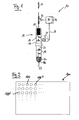
- FIG. 3 shows in cross-sectional view a section of a sample treatment assembly (or a pipetting head) 100 according to an embodiment of the present invention for installation in an automated pipetting apparatus.
- the in FIG. 3 The section shown here shows one of the plurality of pipetting units 110 that are provided in the sample treatment arrangement 100.
- the pipetting unit 110 can, in terms of its functional components, be analogous to that already described in FIG. 1 be schematically shown pipetting 10.
- the following are therefore those components that are already in FIG. 1 shown components, with the same reference numerals, respectively increased by 100, designated and explained only to the extent that they differ from the embodiment according to FIG. 1 to which otherwise reference is made.
- the essential aspect lies in the sample treatment arrangement 100 or in particular the pipetting unit 110 in the arrangement of the piston / cylinder system 112 and the pressure sensor 126 and in the attachment of the piston / cylinder system 112 on the lower support plate 142 of a support device 140 such that the cylinder element (formed by the pipetting cylinder 116 with attached pipette tip 118) is movable relative to the support device 140 (see the double arrow K).
- the support device 140 includes a lower support plate 142 and an upper support plate 144 held together by respective bolts 146. Between the lower support plate 142 and the upper support plate 144, a gap 148 is left open.
- this arrangement is based on the in FIG. 3 12, it being understood that on the carrier device 140, a plurality of pipetting units 110 in the in. In FIG. 3 are shown shown manner.
- a recess 150 In the underside of the lower support plate 142 is a recess 150, in which a sleeve 152 is inserted. In the sleeve 152 is in turn the piston member 114 of the piston / cylinder system 112 is used. The piston member 114 is therefore held firmly and immovably on the lower support plate 142.
- the piston member 114 is formed as a hollow piston, with a jacket 114c, which encloses a concentric with the longitudinal axis of the piston member 114 and the longitudinal axis A of the piston / cylinder system 112 extending passage D.
- the hollow piston 114 is substantially fluid-tightly inserted into a cylinder element, which is formed from a cylinder piston 116 with attached at its front end pipette tip 118.
- the movable together with the support device 140 hollow piston 114 moves along the movement of the support device 140 (see double arrow K) along the inner wall of the Zylinderelelments 116, 118, wherein its outer wall slides on this inner wall.
- the passage D of the hollow piston 114 opens on its one end face, which faces the pipette tip 118 with the first opening 122 formed therein through which the liquid 120 to be pipetted is taken or discharged, into a first partial cavity 154 FIG. 3 the mouth of the passage D is in the partial cavity 154 of the first opening 122 with respect to the longitudinal axis A of the piston / cylinder system 112 against.
- the passage D opens into a second partial cavity 156.
- the second partial cavity 156 is formed by the fact that in the lower support plate 142 along the central axis of the recess 150, a channel is formed, which provides a passage to the top of the lower support plate 142, and at the top of the lower support plate 142 directly above the mouth of the channel, a pressure measuring unit is mounted. The pressure measuring unit is thus accommodated in the intermediate space 148 formed between the two support plates 142, 144.
- the pressure measuring unit comprises a substrate 162 arranged directly above the mouth of the channel which intersects the carrier plate 142 and the actual pressure sensor 126 arranged above the substrate.
- the substrate 162 has an opening which is arranged concentrically with the channel of the carrier plate 142.
- the pressure sensor 126 includes a diaphragm that spans the aperture of the substrate 162 at the top thereof. The pressure sensor 126 thus closes a second opening 136 formed on the upper side of the substrate 162.
- the substrate 162 itself is sealed against the carrier plate 142 by an O-ring seal 164 in a fluid-tight manner.
- the pressure sensor 126 is fluid-tightly connected to the substrate 162 by means of an annular adhesive layer 166. It is pressed by a pressure sensor cover 166 and a ring plate 168, which abuts by means of another adhesive layer 170 on the underside of the upper support plate 144 by tightening the bolts 146 against the substrate so that both between the pressure sensor 126 and the substrate 162 and between the substrate 162 and the support plate 142 creates a fluid-tight contact. Thus, the fluid 124 can not escape from the second part of the cavity 156.
- FIG. 3 It can also be seen that the second opening 136, which is closed by the pressure sensor 126, relative to the longitudinal axis of the piston / cylinder system 112 of the first opening 122 is opposite.
- the signals supplied by the pressure sensor 126 are transmitted via a wire connection 172 and a printed circuit board 174 to an electronic control unit (not shown in the figure) and electronic amplifier unit / evaluation unit.
- electronic control unit not shown in the figure
- electronic amplifier unit / evaluation unit may also be provided in the space 148 or possibly at the top of the upper support plate 144, thus resulting in a short transmission path for the electrical signals. This leads to an improved quality of the transmitted signals and allows on the other hand a fast control and evaluation of the signals by appropriate Mikropozessor- or microcontroller circuits.
Priority Applications (5)
| Application Number | Priority Date | Filing Date | Title |
|---|---|---|---|
| AT07011822T ATE526085T1 (de) | 2007-06-15 | 2007-06-15 | Probenbehandlungsanordnung für eine flüssigkeitsdosiervorrichtung |
| EP07011822A EP2006020B1 (de) | 2007-06-15 | 2007-06-15 | Probenbehandlungsanordnung für eine Flüssigkeitsdosiervorrichtung |
| ES07011822T ES2370119T3 (es) | 2007-06-15 | 2007-06-15 | Conjunto de tratamiento de muestras para un dispositivo de dosificación de líquidos. |
| EP08008466.8A EP2006022B1 (de) | 2007-06-15 | 2008-05-05 | Probenbehandlungsanordnung für eine Flüssigkeitsdosiervorrichtung |
| ES08008466T ES2571788T3 (es) | 2007-06-15 | 2008-05-05 | Modelo de tratamiento de muestras para un dispositivo de dosificación de líquidos |
Applications Claiming Priority (1)
| Application Number | Priority Date | Filing Date | Title |
|---|---|---|---|
| EP07011822A EP2006020B1 (de) | 2007-06-15 | 2007-06-15 | Probenbehandlungsanordnung für eine Flüssigkeitsdosiervorrichtung |
Publications (2)
| Publication Number | Publication Date |
|---|---|
| EP2006020A1 EP2006020A1 (de) | 2008-12-24 |
| EP2006020B1 true EP2006020B1 (de) | 2011-09-28 |
Family
ID=38668725
Family Applications (2)
| Application Number | Title | Priority Date | Filing Date |
|---|---|---|---|
| EP07011822A Active EP2006020B1 (de) | 2007-06-15 | 2007-06-15 | Probenbehandlungsanordnung für eine Flüssigkeitsdosiervorrichtung |
| EP08008466.8A Active EP2006022B1 (de) | 2007-06-15 | 2008-05-05 | Probenbehandlungsanordnung für eine Flüssigkeitsdosiervorrichtung |
Family Applications After (1)
| Application Number | Title | Priority Date | Filing Date |
|---|---|---|---|
| EP08008466.8A Active EP2006022B1 (de) | 2007-06-15 | 2008-05-05 | Probenbehandlungsanordnung für eine Flüssigkeitsdosiervorrichtung |
Country Status (3)
| Country | Link |
|---|---|
| EP (2) | EP2006020B1 (es) |
| AT (1) | ATE526085T1 (es) |
| ES (2) | ES2370119T3 (es) |
Families Citing this family (3)
| Publication number | Priority date | Publication date | Assignee | Title |
|---|---|---|---|---|
| US8231842B2 (en) | 2010-01-22 | 2012-07-31 | Tecan Trading Ag | Positive displacement pump with pressure sensor |
| DE102017201114A1 (de) * | 2017-01-24 | 2018-07-26 | Hamilton Bonaduz Ag | Pipettiervorrichtung zur impulsartigen Pipettierung mit einer basierend auf einer Erfassung des Arbeitsgasdrucks geregelten Pipettierkolbenbewegung |
| WO2020012263A1 (en) * | 2018-07-09 | 2020-01-16 | Presens Precision Sensing Gmbh | System for analysis of a fluid sample |
Family Cites Families (7)
| Publication number | Priority date | Publication date | Assignee | Title |
|---|---|---|---|---|
| JP3318629B2 (ja) * | 1993-06-18 | 2002-08-26 | ソニー株式会社 | 液体の吸引/排出装置及び方法 |
| US5503036A (en) * | 1994-05-09 | 1996-04-02 | Ciba Corning Diagnostics Corp. | Obstruction detection circuit for sample probe |
| EP1412759B1 (de) | 2001-03-09 | 2005-12-21 | Hamilton Bonaduz AG | Verfahren und vorrichtung zur beurteilung eines flüssigkeitsdosierungsvorgangs |
| ATE452704T1 (de) * | 2002-07-23 | 2010-01-15 | Protedyne Corp | Flüssigkeitshandhabungsinstrument mit einem hohlen kolben |
| ATE348659T1 (de) * | 2004-07-02 | 2007-01-15 | Hamilton Bonaduz Ag | Abtropfsichere pipettiervorrichtung und abtropfsicheres pipettierverfahren |
| EP1745851B1 (de) * | 2005-07-22 | 2015-02-25 | Tecan Trading AG | Verfahren, Vorrichtung und Computerprogrammprodukt zum Klassifizieren einer Flüssigkeit |
| JP2007322319A (ja) * | 2006-06-02 | 2007-12-13 | Olympus Corp | サンプル分注装置 |
-
2007
- 2007-06-15 EP EP07011822A patent/EP2006020B1/de active Active
- 2007-06-15 AT AT07011822T patent/ATE526085T1/de active
- 2007-06-15 ES ES07011822T patent/ES2370119T3/es active Active
-
2008
- 2008-05-05 EP EP08008466.8A patent/EP2006022B1/de active Active
- 2008-05-05 ES ES08008466T patent/ES2571788T3/es active Active
Also Published As
| Publication number | Publication date |
|---|---|
| ATE526085T1 (de) | 2011-10-15 |
| ES2571788T3 (es) | 2016-05-26 |
| EP2006022A1 (de) | 2008-12-24 |
| EP2006022B1 (de) | 2016-04-13 |
| EP2006020A1 (de) | 2008-12-24 |
| ES2370119T3 (es) | 2011-12-12 |
Similar Documents
| Publication | Publication Date | Title |
|---|---|---|
| DE60317305T2 (de) | Kontaktloses verfahren zur verteilung geringer flüssigkeitsmengen | |
| DE69727422T2 (de) | Vorrichtung zur Handhabung von Mikroflüssigkeitsmengen | |
| EP1745851B1 (de) | Verfahren, Vorrichtung und Computerprogrammprodukt zum Klassifizieren einer Flüssigkeit | |
| DE102006034245C5 (de) | Positioniereinrichtung zur Positionierung von Pipetten | |
| DE60013983T2 (de) | Mehrkanal-Pipettensystem und Pipettenspitzen dafür | |
| DE10116614C5 (de) | Automatisierbare Meß-, Reinigungs- und Kalibriereinrichtung für pH-Elektroden oder Elektroden zur Messung von Redoxpotentialen | |
| DE102007010345B4 (de) | Verfahren und Vorrichtung zum Kalibrieren und/oder Equilibrieren von ein- und mehrkanaligen Liquidhandlinggeräten | |
| DE10236029A1 (de) | Einrichtung zum Dispensieren und Beobachten der Lumineszenz von Einzelproben in Multiprobenanordnungen | |
| DE102006009816A1 (de) | System und Verfahren zum Titrieren von Flüssigkeiten | |
| EP2437890A1 (de) | Vorrichtung zum transportieren eines fluids in einem kanalstrang eines mikrofluidelements | |
| DE10052819A1 (de) | Pipettensystem und Pipettenarray | |
| WO1986007151A1 (en) | Maintenance installation for the at least partially automatic cleaning and calibration of a measurement sensor probe | |
| DE4029746A1 (de) | Vorrichtung und verfahren zur gleichzeitigen messung verschiedener physikalischer und chemischer parameter einer fluessigkeit | |
| DE69827952T2 (de) | Mikrovolumenfluessigkeitshandhabungssystem | |
| EP1424130B1 (de) | Mehrkanaldosiervorrichtung mit automatischer Kalibrierung | |
| DE4314180C2 (de) | Vorrichtung zum Überführen von Proben in einem Analysegerät | |
| DE102017216713B4 (de) | Verfahren und Dosiervorrichtung zur dosierten Fluidausgabe | |
| EP2006020B1 (de) | Probenbehandlungsanordnung für eine Flüssigkeitsdosiervorrichtung | |
| EP3285074B1 (de) | Mikrodosiereinrichtung und automatisches mikrodosierverfahren | |
| EP2193847A1 (de) | Koaxialnadel und Pipettiervorrichtung | |
| EP2156890B1 (de) | Anordnung und Verfahren zum Erzeugen, Manipulieren und Analysieren von Kompartimenten | |
| DE102007019186B4 (de) | Pipettiergerät und Verfahren für dem Betrieb des Pipettiergerätes | |
| EP1351766A2 (de) | Vorrichtung und verfahren zum dosieren kleiner flüssigkeitsmengen | |
| EP0944814A1 (de) | Verfahren und vorrichtung zur bestimmung des volumens eines gases und/oder des materialvolumens einer probe aus feststoff- und/oder flüssigstoff-material | |
| EP3519781B1 (de) | Verteilerkopf für eine saugpumpe |
Legal Events
| Date | Code | Title | Description |
|---|---|---|---|
| PUAI | Public reference made under article 153(3) epc to a published international application that has entered the european phase |
Free format text: ORIGINAL CODE: 0009012 |
|
| AK | Designated contracting states |
Kind code of ref document: A1 Designated state(s): AT BE BG CH CY CZ DE DK EE ES FI FR GB GR HU IE IS IT LI LT LU LV MC MT NL PL PT RO SE SI SK TR |
|
| AX | Request for extension of the european patent |
Extension state: AL BA HR MK RS |
|
| 17P | Request for examination filed |
Effective date: 20081223 |
|
| R17P | Request for examination filed (corrected) |
Effective date: 20081223 |
|
| 17Q | First examination report despatched |
Effective date: 20090630 |
|
| AKX | Designation fees paid |
Designated state(s): AT BE BG CH CY CZ DE DK EE ES FI FR GB GR HU IE IS IT LI LT LU LV MC MT NL PL PT RO SE SI SK TR |
|
| GRAP | Despatch of communication of intention to grant a patent |
Free format text: ORIGINAL CODE: EPIDOSNIGR1 |
|
| GRAS | Grant fee paid |
Free format text: ORIGINAL CODE: EPIDOSNIGR3 |
|
| GRAA | (expected) grant |
Free format text: ORIGINAL CODE: 0009210 |
|
| AK | Designated contracting states |
Kind code of ref document: B1 Designated state(s): AT BE BG CH CY CZ DE DK EE ES FI FR GB GR HU IE IS IT LI LT LU LV MC MT NL PL PT RO SE SI SK TR |
|
| REG | Reference to a national code |
Ref country code: GB Ref legal event code: FG4D Free format text: NOT ENGLISH |
|
| REG | Reference to a national code |
Ref country code: CH Ref legal event code: NV Representative=s name: BOHEST AG Ref country code: CH Ref legal event code: EP |
|
| REG | Reference to a national code |
Ref country code: IE Ref legal event code: FG4D |
|
| REG | Reference to a national code |
Ref country code: DE Ref legal event code: R096 Ref document number: 502007008239 Country of ref document: DE Effective date: 20111124 |
|
| REG | Reference to a national code |
Ref country code: ES Ref legal event code: FG2A Ref document number: 2370119 Country of ref document: ES Kind code of ref document: T3 Effective date: 20111212 |
|
| REG | Reference to a national code |
Ref country code: NL Ref legal event code: VDEP Effective date: 20110928 |
|
| PG25 | Lapsed in a contracting state [announced via postgrant information from national office to epo] |
Ref country code: LT Free format text: LAPSE BECAUSE OF FAILURE TO SUBMIT A TRANSLATION OF THE DESCRIPTION OR TO PAY THE FEE WITHIN THE PRESCRIBED TIME-LIMIT Effective date: 20110928 Ref country code: SE Free format text: LAPSE BECAUSE OF FAILURE TO SUBMIT A TRANSLATION OF THE DESCRIPTION OR TO PAY THE FEE WITHIN THE PRESCRIBED TIME-LIMIT Effective date: 20110928 Ref country code: FI Free format text: LAPSE BECAUSE OF FAILURE TO SUBMIT A TRANSLATION OF THE DESCRIPTION OR TO PAY THE FEE WITHIN THE PRESCRIBED TIME-LIMIT Effective date: 20110928 |
|
| LTIE | Lt: invalidation of european patent or patent extension |
Effective date: 20110928 |
|
| PG25 | Lapsed in a contracting state [announced via postgrant information from national office to epo] |
Ref country code: GR Free format text: LAPSE BECAUSE OF FAILURE TO SUBMIT A TRANSLATION OF THE DESCRIPTION OR TO PAY THE FEE WITHIN THE PRESCRIBED TIME-LIMIT Effective date: 20111229 Ref country code: CY Free format text: LAPSE BECAUSE OF FAILURE TO SUBMIT A TRANSLATION OF THE DESCRIPTION OR TO PAY THE FEE WITHIN THE PRESCRIBED TIME-LIMIT Effective date: 20110928 Ref country code: LV Free format text: LAPSE BECAUSE OF FAILURE TO SUBMIT A TRANSLATION OF THE DESCRIPTION OR TO PAY THE FEE WITHIN THE PRESCRIBED TIME-LIMIT Effective date: 20110928 Ref country code: SI Free format text: LAPSE BECAUSE OF FAILURE TO SUBMIT A TRANSLATION OF THE DESCRIPTION OR TO PAY THE FEE WITHIN THE PRESCRIBED TIME-LIMIT Effective date: 20110928 |
|
| REG | Reference to a national code |
Ref country code: IE Ref legal event code: FD4D |
|
| PG25 | Lapsed in a contracting state [announced via postgrant information from national office to epo] |
Ref country code: IS Free format text: LAPSE BECAUSE OF FAILURE TO SUBMIT A TRANSLATION OF THE DESCRIPTION OR TO PAY THE FEE WITHIN THE PRESCRIBED TIME-LIMIT Effective date: 20120128 Ref country code: CZ Free format text: LAPSE BECAUSE OF FAILURE TO SUBMIT A TRANSLATION OF THE DESCRIPTION OR TO PAY THE FEE WITHIN THE PRESCRIBED TIME-LIMIT Effective date: 20110928 Ref country code: SK Free format text: LAPSE BECAUSE OF FAILURE TO SUBMIT A TRANSLATION OF THE DESCRIPTION OR TO PAY THE FEE WITHIN THE PRESCRIBED TIME-LIMIT Effective date: 20110928 |
|
| PG25 | Lapsed in a contracting state [announced via postgrant information from national office to epo] |
Ref country code: RO Free format text: LAPSE BECAUSE OF FAILURE TO SUBMIT A TRANSLATION OF THE DESCRIPTION OR TO PAY THE FEE WITHIN THE PRESCRIBED TIME-LIMIT Effective date: 20110928 Ref country code: PT Free format text: LAPSE BECAUSE OF FAILURE TO SUBMIT A TRANSLATION OF THE DESCRIPTION OR TO PAY THE FEE WITHIN THE PRESCRIBED TIME-LIMIT Effective date: 20120130 Ref country code: EE Free format text: LAPSE BECAUSE OF FAILURE TO SUBMIT A TRANSLATION OF THE DESCRIPTION OR TO PAY THE FEE WITHIN THE PRESCRIBED TIME-LIMIT Effective date: 20110928 Ref country code: NL Free format text: LAPSE BECAUSE OF FAILURE TO SUBMIT A TRANSLATION OF THE DESCRIPTION OR TO PAY THE FEE WITHIN THE PRESCRIBED TIME-LIMIT Effective date: 20110928 |
|
| PG25 | Lapsed in a contracting state [announced via postgrant information from national office to epo] |
Ref country code: IE Free format text: LAPSE BECAUSE OF FAILURE TO SUBMIT A TRANSLATION OF THE DESCRIPTION OR TO PAY THE FEE WITHIN THE PRESCRIBED TIME-LIMIT Effective date: 20110928 Ref country code: DK Free format text: LAPSE BECAUSE OF FAILURE TO SUBMIT A TRANSLATION OF THE DESCRIPTION OR TO PAY THE FEE WITHIN THE PRESCRIBED TIME-LIMIT Effective date: 20110928 |
|
| PLBE | No opposition filed within time limit |
Free format text: ORIGINAL CODE: 0009261 |
|
| STAA | Information on the status of an ep patent application or granted ep patent |
Free format text: STATUS: NO OPPOSITION FILED WITHIN TIME LIMIT |
|
| PG25 | Lapsed in a contracting state [announced via postgrant information from national office to epo] |
Ref country code: PL Free format text: LAPSE BECAUSE OF FAILURE TO SUBMIT A TRANSLATION OF THE DESCRIPTION OR TO PAY THE FEE WITHIN THE PRESCRIBED TIME-LIMIT Effective date: 20110928 |
|
| 26N | No opposition filed |
Effective date: 20120629 |
|
| REG | Reference to a national code |
Ref country code: DE Ref legal event code: R097 Ref document number: 502007008239 Country of ref document: DE Effective date: 20120629 |
|
| BERE | Be: lapsed |
Owner name: HAMILTON BONADUZ A.G. Effective date: 20120630 |
|
| PG25 | Lapsed in a contracting state [announced via postgrant information from national office to epo] |
Ref country code: MC Free format text: LAPSE BECAUSE OF NON-PAYMENT OF DUE FEES Effective date: 20120630 |
|
| PG25 | Lapsed in a contracting state [announced via postgrant information from national office to epo] |
Ref country code: BE Free format text: LAPSE BECAUSE OF NON-PAYMENT OF DUE FEES Effective date: 20120630 |
|
| PG25 | Lapsed in a contracting state [announced via postgrant information from national office to epo] |
Ref country code: BG Free format text: LAPSE BECAUSE OF FAILURE TO SUBMIT A TRANSLATION OF THE DESCRIPTION OR TO PAY THE FEE WITHIN THE PRESCRIBED TIME-LIMIT Effective date: 20111228 |
|
| PG25 | Lapsed in a contracting state [announced via postgrant information from national office to epo] |
Ref country code: MT Free format text: LAPSE BECAUSE OF FAILURE TO SUBMIT A TRANSLATION OF THE DESCRIPTION OR TO PAY THE FEE WITHIN THE PRESCRIBED TIME-LIMIT Effective date: 20110928 |
|
| PG25 | Lapsed in a contracting state [announced via postgrant information from national office to epo] |
Ref country code: TR Free format text: LAPSE BECAUSE OF FAILURE TO SUBMIT A TRANSLATION OF THE DESCRIPTION OR TO PAY THE FEE WITHIN THE PRESCRIBED TIME-LIMIT Effective date: 20110928 |
|
| PG25 | Lapsed in a contracting state [announced via postgrant information from national office to epo] |
Ref country code: LU Free format text: LAPSE BECAUSE OF NON-PAYMENT OF DUE FEES Effective date: 20120615 |
|
| REG | Reference to a national code |
Ref country code: CH Ref legal event code: PCAR Free format text: NEW ADDRESS: HOLBEINSTRASSE 36-38, 4051 BASEL (CH) |
|
| PG25 | Lapsed in a contracting state [announced via postgrant information from national office to epo] |
Ref country code: HU Free format text: LAPSE BECAUSE OF FAILURE TO SUBMIT A TRANSLATION OF THE DESCRIPTION OR TO PAY THE FEE WITHIN THE PRESCRIBED TIME-LIMIT Effective date: 20070615 |
|
| REG | Reference to a national code |
Ref country code: DE Ref legal event code: R082 Ref document number: 502007008239 Country of ref document: DE Representative=s name: RUTTENSPERGER LACHNIT TROSSIN GOMOLL PATENT- U, DE Ref country code: DE Ref legal event code: R082 Ref document number: 502007008239 Country of ref document: DE Representative=s name: RUTTENSPERGER LACHNIT TROSSIN GOMOLL, PATENT- , DE |
|
| REG | Reference to a national code |
Ref country code: FR Ref legal event code: PLFP Year of fee payment: 9 |
|
| REG | Reference to a national code |
Ref country code: FR Ref legal event code: PLFP Year of fee payment: 10 |
|
| REG | Reference to a national code |
Ref country code: FR Ref legal event code: PLFP Year of fee payment: 11 |
|
| REG | Reference to a national code |
Ref country code: FR Ref legal event code: PLFP Year of fee payment: 12 |
|
| P01 | Opt-out of the competence of the unified patent court (upc) registered |
Effective date: 20230521 |
|
| PGFP | Annual fee paid to national office [announced via postgrant information from national office to epo] |
Ref country code: IT Payment date: 20230523 Year of fee payment: 17 Ref country code: FR Payment date: 20230523 Year of fee payment: 17 Ref country code: DE Payment date: 20230523 Year of fee payment: 17 |
|
| PGFP | Annual fee paid to national office [announced via postgrant information from national office to epo] |
Ref country code: AT Payment date: 20230525 Year of fee payment: 17 |
|
| PGFP | Annual fee paid to national office [announced via postgrant information from national office to epo] |
Ref country code: GB Payment date: 20230523 Year of fee payment: 17 Ref country code: ES Payment date: 20230703 Year of fee payment: 17 Ref country code: CH Payment date: 20230702 Year of fee payment: 17 |